


 Loading...
FS-C8520MFP FS-C8525MFP
PARTS LIST
Published in March 2012
2MYPL070
842MY120
First Edition

CONTENTS
FIG. 1 |
Covers .................................................................... |
2 |
FIG. 11 |
Image Formation Section ...................................... |
22 |
FIG. 2 |
Frames 1 ................................................................ |
4 |
FIG. 12 |
Transfer Section .................................................... |
24 |
FIG. 3 |
Frames 2 ................................................................ |
6 |
FIG. 13 |
Fuser Section ........................................................ |
26 |
FIG. 4 |
Paper Cassette ....................................................... |
8 |
FIG. 14 |
Drive Section ......................................................... |
28 |
FIG. 5 |
Paper Feed Section .............................................. |
10 |
FIG. 15 |
Electrical Components ........................................... |
30 |
FIG. 6 |
Exit Section ........................................................... |
12 |
FIG. 16 |
Operation Section .................................................. |
32 |
FIG. 7 |
Paper Conveying Section ..................................... |
14 |
FIG. 17 |
Document Processor1 ........................................... |
34 |
FIG. 8 |
Scanner Section ................................................... |
16 |
FIG. 18 |
Document Processor2............................................ |
36 |
FIG. 9 |
Laser Scanner Section ......................................... |
18 |
FIG. 19 |
Document Processor3 ........................................... |
38 |
FIG. 10 |
Developing Section ............................................... |
20 |
FIG. 20 |
Maintenance Kits ................................................... |
40 |
|
|
|
|
• INDEX .................................................................. |
41 |
- 1 -
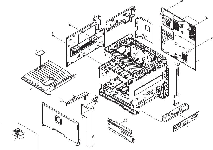
FIG. 1 Covers |
2MZ/2MY |

 101
101
9
8
11 |
101 |
101
101

 101
101
3
A
B
7 |
10 |
|
15
14
4 |
12 |
6 |
B
1
2 |
A |
13
5
16
- 2 -

FIG. 1 Covers |
|
|
|
|
|
|
|
2MZ/2MY |
|
Ref. |
Part.No. |
Alternative. |
Description |
|
Notes |
|
Quantity |
|
|
No. |
|
120 |
230 |
240 |
|
||||
|
|
|
|
|
|
||||
1 |
302MZ94020 |
2MZ94020 |
PARTS COVER FRONT ASSY 20 E SP |
20ppm |
|
|
1 |
1 |
|
1 |
302MY94020 |
2MY94020 |
PARTS COVER FRONT ASSY 25 E SP |
25ppm |
|
|
1 |
1 |
|
1 |
302MZ94010 |
2MZ94010 |
PARTS COVER FRONT ASSY 20 J/A SP |
20ppm |
|
1 |
|
|
|
1 |
302MY94010 |
2MY94010 |
PARTS COVER FRONT ASSY 25 J/A SP |
25ppm |
|
1 |
|
|
|
2 |
302K004020 |
2K004020 |
COVER FRONT TOP |
|
|
1 |
1 |
1 |
|
3 |
302H004560 |
2H004560 |
STOPPER PAPER |
|
|
1 |
1 |
1 |
|
4 |
302K004031 |
2K004031 |
COVER TRAY |
|
|
1 |
1 |
1 |
|
5 |
302K004040 |
2K004040 |
COVER EXIT REAR |
|
|
1 |
1 |
1 |
|
6 |
302K004050 |
2K004050 |
COVER EXIT FRONT |
|
|
1 |
1 |
1 |
|
7 |
302K004060 |
2K004060 |
COVER RIGHT REAR |
|
|
1 |
1 |
1 |
|
8 |
302K004100 |
2K004100 |
COVER LEFT LOW |
|
|
1 |
1 |
1 |
|
9 |
302K004110 |
2K004110 |
COVER LEFT TOP |
|
|
1 |
1 |
1 |
|
10 |
302K094430 |
2K094430 |
PARTS COVER REAR ASSY E SP |
|
|
|
1 |
1 |
|
10 |
302K094370 |
2K094370 |
PARTS COVER REAR ASSY SP |
|
|
1 |
|
|
|
11 |
302K004170 |
2K004170 |
LID CONTROLLER BOX |
|
|
1 |
1 |
1 |
|
12 |
302K004180 |
2K004180 |
COVER TRAY LEFT |
|
|
1 |
1 |
1 |
|
13 |
302K304070 |
2K304070 |
COVER RIGHT LOW |
|
|
1 |
1 |
1 |
|
14 |
302K094380 |
2K094380 |
PARTS COVER RIGHT TOP ASSY SP |
|
|
1 |
1 |
1 |
|
15 |
302K304290 |
2K304290 |
COVER EXIT FRONT TOP |
|
|
1 |
1 |
1 |
|
16 |
302K093110 |
2K093110 |
WT-895 |
|
|
1 |
1 |
1 |
|
101 7BB702308H |
BB107060 |
+TP-FLAT T.T S SCREW 3X8 SR |
•Parts with Ref.No. indicate maintenance parts and the ones without it indicate out of the above.
|
•Parts with "•" are component parts or sub-assemblies of the |
|
assembly appearing immediately above them. |
- 3 - |
•Parts with "• •" are component parts or sub-assembly with "•" |
appearing immediately above them. |

FIG. 2 Frames 1 |
2MZ/2MY |
13
10
14


B
102
3
7
11
|
21 |
|
|
|
C |
102 |
|
|
|
|
|
1 |
|
|
|
B |
|
|
|
|
|
||
12 |
2 |
|
1 |
|
|
|
|
2 |
|
|
|
|
|
|
21 |
|
|
|
|
|
102 |
4 |
9 |
|
|
|
|
||
|
|
|
|
|
|
C |
|
|
|
5 |
|
|
15 |
A |
|
8 |
|
|
103 |
7 |
6 |
101 |
|
|
|
|
|
|
|
|
|
103 |
|
8 |
|
|
|
|
7 |
||
|
|
|
|
|
|
|
|
7 |
101 |
|
A |
16 |
17 |
|
18
19
- 4 -

FIG. 2 Frames 1 |
|
|
|
|
|
|
2MZ/2MY |
|
Ref. |
Part.No. |
Alternative. |
Description |
Notes |
|
Quantity |
|
|
No. |
120 |
230 |
240 |
|
||||
|
|
|
|
|
||||
1 |
302K015230 |
2K015230 |
GEAR IDLE Z22S |
|
4 |
4 |
4 |
|
2 |
302K015240 |
2K015240 |
GEAR JOINT Z26S |
|
4 |
4 |
4 |
|
3 |
302K002230 |
2K002230 |
ACTUATOR PAPER EMPTY |
|
1 |
1 |
1 |
|
4 |
302K094100 |
2K094100 |
PARTS DC MOTOR SP |
|
1 |
1 |
1 |
|
5 |
302K002880 |
2K002880 |
WORM-WHEEL ID SENSOR CLEANING |
|
1 |
1 |
1 |
|
6 |
302K002890 |
2K002890 |
GEAR ID SENSOR CLEANING Z71R |
|
1 |
1 |
1 |
|
7 |
7NXGP1S173LCH01 |
NX116910 |
SENSOR OPT. |
|
4 |
4 |
4 |
|
8 |
302K094290 |
2K094290 |
PARTS ID SENSOR ASSY ASSY SP |
|
2 |
2 |
2 |
|
9 |
302K026120 |
2K026120 |
GEAR IDLE Z20S |
|
2 |
2 |
2 |
|
10 |
302K094041 |
2K094041 |
PARTS PIPE TRANSFER CLEANING ASSY SP |
|
1 |
1 |
1 |
|
11 |
302K094050 |
2K094050 |
PARTS TONER SUPPLY ASSY SP |
|
4 |
4 |
4 |
|
12 |
302K094180 |
2K094180 |
PARTS PWB DRUM DLP CONNECT ASSY SP |
|
1 |
1 |
1 |
|
13 |
302K031720 |
2K031720 |
GEAR BELT CLEANING DRIVE Z30L |
|
1 |
1 |
1 |
|
14 |
302K031740 |
2K031740 |
GEAR BELT CLEANING DRIVE Z20L |
|
1 |
1 |
1 |
|
15 |
302K394190 |
2K394190 |
PARTS MOTOR LIFT ASSY SP |
|
1 |
1 |
1 |
|
16 |
302K302830 |
2K302830 |
ACTUATOR DECK FEED |
|
1 |
1 |
1 |
|
17 |
3019527401 |
19527401 |
POWER CORD(120) |
|
1 |
|
|
|
18 |
2AR27800 |
2AR27800 |
POWER CORD(230) |
|
|
1 |
|
|
19 |
7AAACCAS+10H001 |
AA063380 |
AC CORD ASSY AS |
|
|
|
1 |
|
101 |
7BB700308H |
BB105600 |
+BIND T.T S SCREW 3X8 SR |
102 |
7BB200308H |
BB105660 |
+BIND T.T P SCREW 3X8 |
103 |
7BB700312H |
BB106820 |
+BIND T.T S SCREW 3X12 SR |
•Parts with Ref.No. indicate maintenance parts and the ones without it indicate out of the above.
|
•Parts with "•" are component parts or sub-assemblies of the |
|
assembly appearing immediately above them. |
- 5 - |
•Parts with "• •" are component parts or sub-assembly with "•" |
appearing immediately above them. |
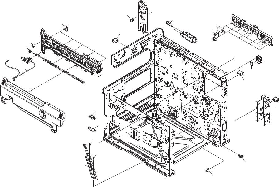
FIG. 3 Frames 2 |
2MZ/2MY |
|
|
|
16 |
|
|
|
1 |
|
3 |
|
7 |
|
|
|
|
|
|
13 |
6 |
|
|
5 |
|
|
|
|
|
8 |
9 |
|
A |
|
|
2
14
A |
15 |
11 |
13 |
4
101
101
12 |
10 |
16
- 6 -

FIG. 3 Frames 2 |
|
|
|
|
|
|
2MZ/2MY |
|
Ref. |
Part.No. |
Alternative. |
Description |
Notes |
|
Quantity |
|
|
No. |
120 |
230 |
240 |
|
||||
|
|
|
|
|
||||
1 |
2FB27160 |
2FB27160 |
INTER LOCK SWITCH |
|
2 |
2 |
2 |
|
2 |
302K094280 |
2K094280 |
PARTS TONER FULL DETECT ASSY SP |
|
1 |
1 |
1 |
|
3 |
302K003280 |
2K003280 |
SEAL CASE WASTE C |
|
5 |
5 |
5 |
|
4 |
302K309410 |
2K309410 |
PLATE SIZE DETECTION |
|
1 |
1 |
1 |
|
5 |
302K015040 |
2K015040 |
GEAR Z50S |
|
4 |
4 |
4 |
|
6 |
302K015030 |
2K015030 |
GEAR Z20S-Z26L |
|
4 |
4 |
4 |
|
7 |
302K094100 |
2K094100 |
PARTS DC MOTOR SP |
|
4 |
4 |
4 |
|
8 |
302K003060 |
2K003060 |
GEAR SCREW WASTE Z13L |
|
1 |
1 |
1 |
|
9 |
302K003110 |
2K003110 |
GEAR WASTE Z13L |
|
1 |
1 |
1 |
|
10 |
7NXGP1S173LCH01 |
NX116910 |
SENSOR OPT. |
|
2 |
2 |
2 |
|
11 |
7SM010303+++H01 |
SM037910 |
SW.MICRO |
|
1 |
1 |
1 |
|
12 |
302K302430 |
2K302430 |
HEATER DEHUMIDIFIER 120 |
|
1 |
|
|
|
12 |
302K302440 |
2K302440 |
HEATER DEHUMIDIFIER 240 |
|
|
1 |
1 |
|
13 |
7SC010105+++H01 |
SC125000 |
SW.SEESAW |
|
2 |
2 |
2 |
|
14 |
7SM010101+++H01 |
SM042310 |
SW.MICRO |
|
1 |
1 |
1 |
|
15 |
5ESP03090001+01 |
SP000360 |
PUSH SWITCH 03 SN /SW-192 N |
|
1 |
1 |
1 |
|
16 |
7SP01000001+H01 |
SP044290 |
SW.PUSH |
|
2 |
2 |
2 |
|
101 7BB700308H |
BB105600 |
+BIND T.T S SCREW 3X8 SR |
•Parts with Ref.No. indicate maintenance parts and the ones without it indicate out of the above.
|
•Parts with "•" are component parts or sub-assemblies of the |
|
assembly appearing immediately above them. |
- 7 - |
•Parts with "• •" are component parts or sub-assembly with "•" |
appearing immediately above them. |
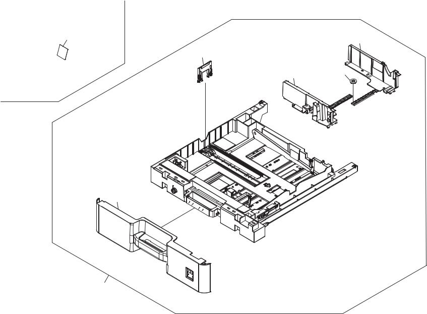
FIG. 4 Paper Cassette |
2MZ/2MY |
6 |
|
4 |
|
|
|
|
2 |
|
|
3 |
5 |
|
|
1
A01
- 8 -
FIG. 4 Paper Cassette |
|
|
|
|
|
2MZ/2MY |
||
Ref. |
Part.No. |
Alternative. |
Description |
Notes |
|
Quantity |
|
|
No. |
120 |
230 |
240 |
|
||||
|
|
|
|
|
||||
A01 |
302K393173 |
2K393173 |
CT-475 |
|
1 |
1 |
1 |
|
1 |
•302K309080 |
2K309080 |
COVER CASSETTE |
|
1 |
1 |
1 |
|
2 |
•302K309270 |
2K309270 |
CURSOR END |
|
1 |
1 |
1 |
|
3 |
•302K309130 |
2K309130 |
CURSOR CASSETTE FRONT |
|
1 |
1 |
1 |
|
4 |
•302K309120 |
2K309120 |
CURSOR CASSETTE REAR |
|
1 |
1 |
1 |
|
5 |
•302K394380 |
2K394380 |
PARTS GEAR Z18 SP |
|
1 |
1 |
1 |
|
6 |
302K334090 |
2K334090 |
SHEET CASSETTE C |
|
|
1 |
1 |
|
6 |
302K334100 |
2K334100 |
SHEET CASSETTE I |
|
1 |
|
|
|
|
|
|
|
|
|
|
|
|
•Parts with Ref.No. indicate maintenance parts and the ones without it indicate out of the above.
|
•Parts with "•" are component parts or sub-assemblies of the |
|
assembly appearing immediately above them. |
- 9 - |
•Parts with "• •" are component parts or sub-assembly with "•" |
appearing immediately above them. |
FIG. 5 Paper Feed Section |
2MZ/2MY |
A01
3
A02
7
2
8


6
 5
5 
 4
4

 9 1
9 1 


11
10
 12
12
- 10 -
FIG. 5 Paper Feed Section |
|
|
|
|
|
|
2MZ/2MY |
||
Ref. |
Part.No. |
Alternative. |
Description |
|
Notes |
|
Quantity |
|
|
No. |
|
120 |
230 |
240 |
|
||||
|
|
|
|
|
|
||||
1 |
302K394480 |
2K394480 |
PRIMARY FEED UNIT |
|
|
1 |
1 |
1 |
|
2 |
302K394230 |
2K394230 |
PARTS ROLLER REGIST LEFT SP |
|
|
1 |
1 |
1 |
|
3 |
302K394310 |
2K394310 |
PARTS GEAR REGIST Z28L-Z18L SP |
|
|
1 |
1 |
1 |
|
A01 |
302K394501 |
2K394501 |
PARTS MPF UNIT |
|
|
1 |
1 |
1 |
|
4 |
•302K308020 |
2K308020 |
ACTUATOR MPF |
|
|
1 |
1 |
1 |
|
5 |
•7NXGP1S173LCH01 |
NX116910 |
SENSOR OPT. |
|
|
1 |
1 |
1 |
|
6 |
•302K394320 |
2K394320 |
PARTS GEAR MPF Z28 SP |
|
|
1 |
1 |
1 |
|
A02 |
•302K394621 |
2K394621 |
MPF ROLLER-PAD SET |
for customer |
|
1 |
1 |
1 |
|
7 |
••302K394460 |
2K394460 |
MPF ROLLER |
for customer |
|
1 |
1 |
1 |
|
8 |
••302K394491 |
2K394491 |
SEPARATION PAD |
service only |
|
1 |
1 |
1 |
|
9 |
302K306140 |
2K306140 |
ACTUATOR REGIST |
|
|
1 |
1 |
1 |
|
10 |
302K094330 |
2K094330 |
PARTS ROLLER MIDDLE SP |
|
|
1 |
1 |
1 |
|
11 |
302HS31120 |
2HS31120 |
GEAR Z27L CLUTCH |
|
|
1 |
1 |
1 |
|
12 |
302K094400 |
2K094400 |
REGIST CLEANER |
|
|
1 |
1 |
1 |
|
|
|
|
|
|
|
|
|
|
|
•Parts with Ref.No. indicate maintenance parts and the ones without it indicate out of the above.
|
•Parts with "•" are component parts or sub-assemblies of the |
|
assembly appearing immediately above them. |
- 11 - |
•Parts with "• •" are component parts or sub-assembly with "•" |
appearing immediately above them. |
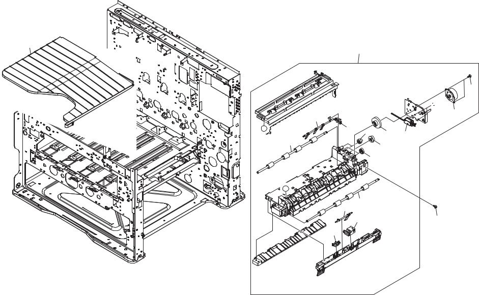
FIG. 6 Exit Section |
2MZ/2MY |
13
A01
102


 101
101
11
|
12 |
|
|
|
A |
3 |
8 |
9 |
10 |
|
|
|||
|
1 |
|
7 |
|
|
|
|
|
|
|
|
|
2 |
|
A
6 |
|
5 |
|
4 |
103 |
3
- 12 -

FIG. |
6 Exit Section |
|
|
|
|
|
|
2MZ/2MY |
Ref. |
Part.No. |
Alternative. |
Description |
Notes |
|
Quantity |
|
|
No. |
120 |
230 |
240 |
|
||||
|
|
|
|
|
||||
A01 |
302K094010 |
2K094010 |
PARTS EXIT UNIT SP |
|
1 |
1 |
1 |
|
1 |
•302K094350 |
2K094350 |
PARTS ROLLER EXIT REVERSE SP |
|
1 |
1 |
1 |
|
2 |
•302K394350 |
2K394350 |
PARTS GEAR Z22S EXIT SP |
|
2 |
2 |
2 |
|
3 |
•7NXGP1S173LCH01 |
NX116910 |
SENSOR OPT. |
|
2 |
2 |
2 |
|
4 |
•302K394180 |
2K394180 |
PARTS SWITCH EXIT PAPER EMPTY SP |
|
1 |
1 |
1 |
|
5 |
•302K028080 |
2K028080 |
ACTUATOR EXIT OVERFLOW LOW |
|
1 |
1 |
1 |
|
6 |
•302K094340 |
2K094340 |
PARTS ROLLER EXIT FD SP |
|
1 |
1 |
1 |
|
7 |
•302K028260 |
2K028260 |
GEAR Z23S EXIT |
|
1 |
1 |
1 |
|
8 |
•302KP29090 |
2KP29090 |
GEAR IDLE Z18S |
|
2 |
2 |
2 |
|
9 |
•302K394340 |
2K394340 |
PARTS GEAR Z74R-Z22S EXIT SP |
|
1 |
1 |
1 |
|
10 |
•303LJ94150 |
3LJ94150 |
PARTS SOLENOID FEED SHIFT SP |
|
1 |
1 |
1 |
|
11 |
•302HN44100 |
2HN44100 |
MOTOR REVERSE |
|
1 |
1 |
1 |
|
12 |
•302K028090 |
2K028090 |
ACTUATOR EXIT OVERFLOW UP |
|
1 |
1 |
1 |
|
13 |
302K004320 |
2K004320 |
TRAY EJECT |
|
1 |
1 |
1 |
|
101 |
7BB000303H |
BB107000 |
+BIND M SCREW 3X3 |
102 |
7BB700308H |
BB105600 |
+BIND T.T S SCREW 3X8 SR |
103 |
7BB200410H |
BB105700 |
+BIND T.T P SCREW 4X10 |
•Parts with Ref.No. indicate maintenance parts and the ones without it indicate out of the above.
|
•Parts with "•" are component parts or sub-assemblies of the |
|
assembly appearing immediately above them. |
- 13 - |
•Parts with "• •" are component parts or sub-assembly with "•" |
appearing immediately above them. |
Loading...