


GFC300
Signal converter for gas ultrasonic flowmeters
Description of Foundation Fieldbus interface
Description of Foundation Fieldbus interfaceDescription of Foundation Fieldbus interface
Description of Foundation Fieldbus interface
Electronic Revision: ER 1.1.xx
GFC 300
GFC 300GFC 300
GFC 300
Supplementary instructions
Supplementary instructions Supplementary instructions
Supplementary instructions
© KROHNE 07/2012 - 4001866001 - AD GFC 300 FF R01 en
The documentation is only complete when used in combination with the relevant
documentation for the measuring sensor.

CONTENTS
2
www.krohne.com 07/2012 - 4001866001 - AD GFC 300 FF R01 en
GFC 300
1 Safety instructions 3
1.1 Scope of the document..................................................................................................... 3
1.2 Device description ............................................................................................................ 3
2 Technical data 4
2.1 Foundation Fieldbus data................................................................................................. 4
3 Electrical connections 5
3.1 Cable types ....................................................................................................................... 5
3.2 Shielding and grounding .................................................................................................. 5
3.3 Electrical connection of FOUNDATION Fieldbus ............................................................. 6
3.4 Topology of FF networks .................................................................................................. 7
4 Operation 8
4.1 Settable functions............................................................................................................. 8
4.2 Description of the FF block system.................................................................................. 9
4.3 Used abbreviations ........................................................................................................... 9
4.4 Resource Block (RB) ...................................................................................................... 10
4.4.1 Foundation Fieldbus parameters for Resource Block......................................................... 10
4.4.2 Manufacturer specific parameters of the signal converter for Resource Block................. 16
4.5 Analog Input Block (AI 1...6) ........................................................................................... 21
4.6 Transducer Block (TB).................................................................................................... 29
4.6.1 Transducer Main Block......................................................................................................... 29
4.6.2 Transducer Auxiliary Block................................................................................................... 39
4.6.3 Transducer Specification Block............................................................................................ 46
4.7 Arithmetic Block (AR) ..................................................................................................... 55
4.8 Integrator Block (IT) ....................................................................................................... 61
4.9 Proportional Integral Derivative Block (PID) ................................................................. 68
5 Notes 82

SAFETY INSTRUCTIONS 1
3
GFC 300
www.krohne.com07/2012 - 4001866001 - AD GFC 300 FF R01 en
1.1 Scope of the document
These instructions are supplementary to the standard product documentation of the signal
converter. The details depicted therein, in particular the safety information are valid and should
be adhered to. The present supplementary instructions provide additional information for the
devices when being operated and connected to a Foundation Fieldbus.
1.2 Device description
The ultrasonic flowmeters are designed exclusively for the continuous measurement of actual
volume flow, mass flow, molar mass, flow speed, velocity of sound, gain, SNR and diagnosis
value.
Your measuring device is supplied ready for operation. The factory settings for the operating
data have been made in accordance with your order specifications.
INFORMATION!
The present supplementary instruction for the signal converter with Foundation Fieldbus
interface, plus the software with the DD and CCF files are included in our scope of supply, in
addition to those items delivered for the standard device.

2 TECHNICAL DATA
4
GFC 300
www.krohne.com 07/2012 - 4001866001 - AD GFC 300 FF R01 en
2.1 Foundation Fieldbus data
Description
Type Ultrasonic flowmeter
Physical layer Foundation Fieldbus protocol that agrees with IEC 61158-2 and FISCO model;
galvanically isolated
Communication standard H1
ITK version 5.2
Data blocks
Function blocks 1 x Enhanced Resource Block (RB)
1 x Customer Transducer Block Main (TB)
1 x Customer Transducer Block Auxiliary (TB)
1 x Customer Transducer Block Special (TB)
6 x Analog Input Block (AI)
2 x Integrator Block (IT)
1 x Proportional Integral Derivate Block (PID)
1x Arithmetic Block (AR)
Execution time Analog Input Block: 10 ms
Integrator Block: 15 ms
Proportional Integral Derivate Block: 25 ms
Arithmetic Block: 20 ms
Electrical connections
Device power supply Not intrinsically safe: 9...32 VDC
Intrinsically safe: 9...24 VDC
Basic current 10.5 mA
Maximum error current 16.5 mA (= basic current + error current = 10.5 mA + 6 mA)
Start current after 10 ms 14 mA
Polarity sensitivity No
Minimum cycle time 250 ms
ELECTRICAL CONNECTIONS 3
5
GFC 300
www.krohne.com07/2012 - 4001866001 - AD GFC 300 FF R01 en
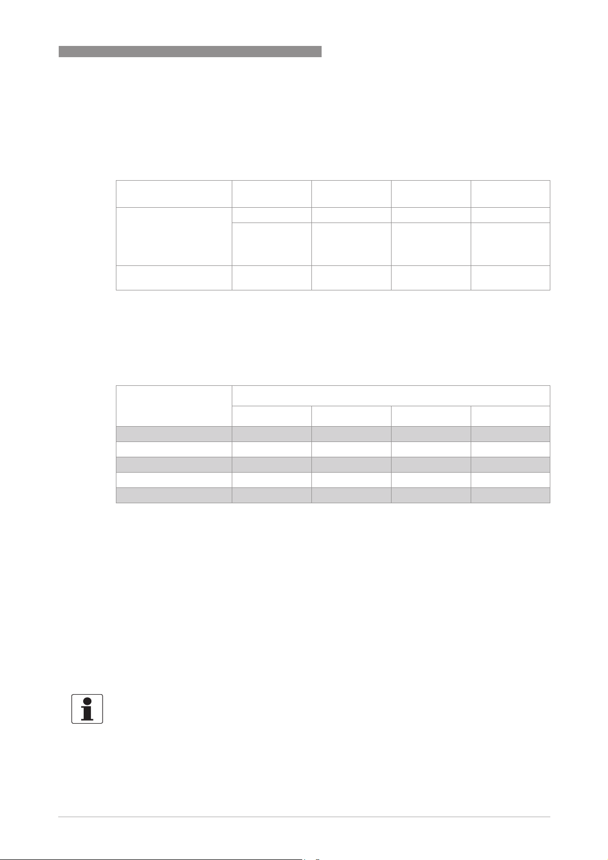
3.1 Cable types
The cable types are specified according to IEC 61158-2. Shielded cables offer the advantage of
malfunction-free operation with adequate protection against electromagnetic influences, and
make it possible to employ the full performance of the Foundation Fieldbus system.
In non-hazardous areas the maximum number of field devices is limited to 32. For detailed
information refer to the following table.
In non-hazardous areas the ignition protection class of the devices and the limited electric power
available limit the number of field devices to 4.
All bus segments must be fitted with a terminator at both ends.
3.2 Shielding and grounding
• For optimum electromagnetic compatibility of systems it is extremely important that the
system components, and particularly the bus cables connecting the components, are
shielded and that such shields - if possible - form an unbroken cover.
• Hence, it follows that, for use in non-hazardous duty systems, the cable shield should be
grounded as often as possible.
• In Ex systems an adequate equipotential bonding in the hazardous and non-hazardous
location along the entire Fieldbus installation is strongly recommended. Multiple grounding
of the shield is of advantage.
Core cross-section
0.8 mm
2
or
AWG 18
0.32 mm
2
or
AWG 22
0.13 mm
2
or
AWG 26
1.25 mm
2
or
AWG 16
Cable type A
AA
A B
BB
B C
CC
C D
DD
D
twisted pair,
individually
shielded
individual or
multiple twisted
pairs with overall
shield
multiple twisted
pairs, without
shielding
multiple non-
twisted cables,
without shielding
Max. length
incl. branch line
1900 m / 6200 ft 1200 m / 3900 ft 400 m / 1300 ft 200 m / 650 ft
Number of devices Cable lengths for number of devices per branch line
1 device 2 devices 3 devices 4 devices
25...32 1m/ 3.3ft 1m/ 3.3ft 1m/ 3.3ft 1m/ 3.3ft
19...24 30 m / 100 ft 1m/ 3.3ft 1m/ 3.3ft 1m/ 3.3ft
15...18 60 m / 200 ft 30 m / 100 ft 1m/ 3.3ft 1m/ 3.3ft
13...14 90 m / 300 ft 60 m / 200 ft 30 m / 100 ft 1m/ 3.3ft
1..12 120 m / 400 ft 90 m / 300 ft 60 m / 200 ft 30 m / 100 ft
INFORMATION!
The use of twisted and shielded cables is strongly recommended, otherwise EMC protection of
the signal converter cannot be assured.

3 ELECTRICAL CONNECTIONS
6
GFC 300
www.krohne.com 07/2012 - 4001866001 - AD GFC 300 FF R01 en
3.3 Electrical connection of FOUNDATION Fieldbus
Connection to a spur
Connection to a trunk
INFORMATION!
The wiring between the device and the FOUNDATION Fieldbus cable is independant of polarity.
The signal converter FOUNDATION Fieldbus interface will operate only if the additional power
supply for the device is connected/available.
For a detailed description of the electrical connections please refer to the standard signal
converter handbook.
or
or
1 e.g. incoming data lines
2 e.g. outgoing data lines
ELECTRICAL CONNECTIONS 3
7
GFC 300
www.krohne.com07/2012 - 4001866001 - AD GFC 300 FF R01 en
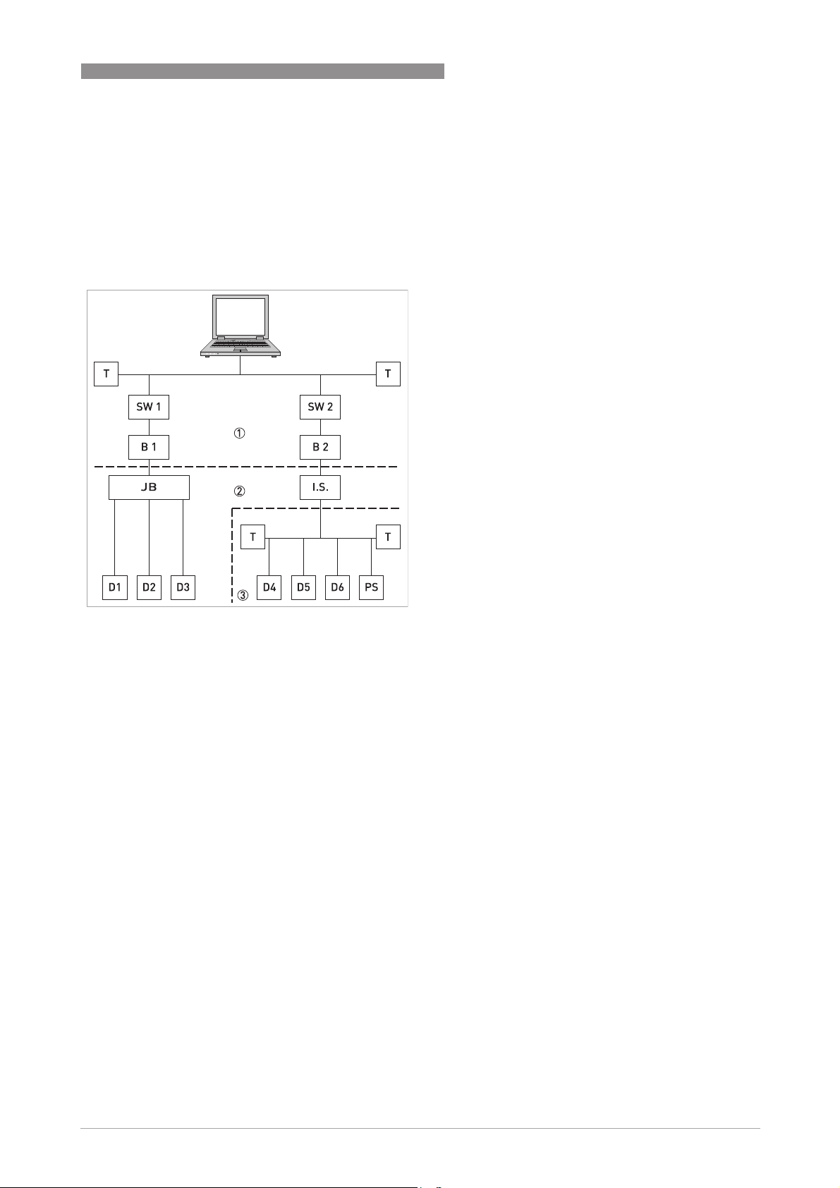
3.4 Topology of FF networks
An example of mixed topology of FF networks is shown in the following example.
Connection is best made via short branch cables and T connectors. This connection type makes it
possible to connect and disconnect the devices without interrupting the bus or the
communication.
1 HSE network
2 H1 bus
3 Intrisically safe, explosive area
B1+B2 Bridge = coupling element for H1 bus
and HSE network
D1-D3 Device = field devices, own power
supply, for non potentially explosive
areas
D4-D6 Intrinsically safe devices, external
power supply, for potentially explosive
areas
I.S. Intrinsically safe barrier
JB Junction box for field devices
PS Power supply
Switch = connection of multiple HSE
sub networks
TTerminator

4 OPERATION
8
GFC 300
www.krohne.com 07/2012 - 4001866001 - AD GFC 300 FF R01 en
4.1 Settable functions
• For Foundation Fieldbus the totalizers of the signal converter are not available!
• The following tables describe only the menus, functions and parameters that are different
between the standard signal converter and the Foundation Fieldbus signal converter.
• For the electrical connections of the outputs, inputs and all settings of functions that are not
listed in the following tables refer to the standard product documentation.
No. Displayed text Description and settings
A quick setup
A2 Tag Identifier for the measurement in a plant, appears in the display header
(maximum 8 digits).
Note: Only read, not changeable!
B test
B3.5 Foundation fieldbus Display information about Foundation fieldbus interface.
C setup
C5.1.1 Tag Identifier for the measurement in a plant, appears in the display header
(maximum 8 digits).
Note: Only read, not changeable!
C3 Totalizer Not available for Foundation Fieldbus devices!
C4 I/O HART Not available for Foundation Fieldbus devices!
C5.4 2. meas. page In case of Foundation Fieldbus device, the second measurement page is
meant to check the output values of the different function blocks. Only
Foundation Fieldbus values can be selected here. The analogue inputs are
shown with exactly the value, seen on the bus system.
C5.4.1 measurement 1.line Select: AI1...6 analog inp. / PID / INT1..2 integrator / AR
C5.4.2 format 1.line Fixed number of digits after the decimal point or automatic, where the
number of digits is automatically adjusted to the available space.
C5.4.3 measurement 2.line Select: AI1...6 analog inp. / PID / INT1..2 integrator / AR
C5.4.4 format 2.line Fixed number of digits after the decimal point or automatic, where the
number of digits is automatically adjusted to the available space.
C5.4.5 measurement 3.line Select: AI1...6 analog inp. / PID / INT1..2 integrator / AR
C5.4.6 format 3.line Fixed number of digits after the decimal point or automatic, where the
number of digits is automatically adjusted to the available space.
C5.8 Foundation Field -
C5.8.1 Simulate Select: disabled / enabled
C5.8.2 Information Display information about hardware and software versions, the calibration
and test date of this interface.
OPERATION 4
9
GFC 300
www.krohne.com07/2012 - 4001866001 - AD GFC 300 FF R01 en
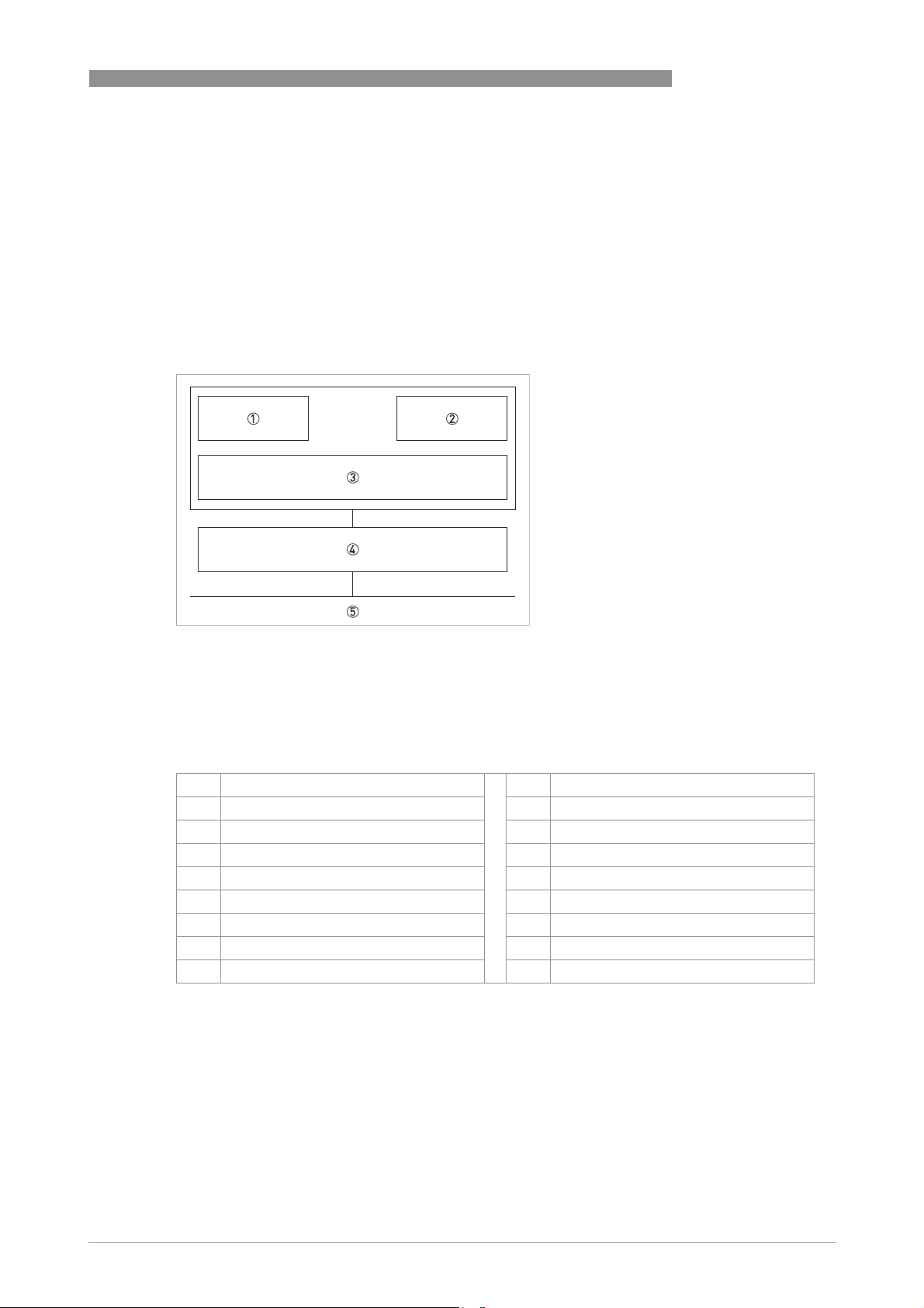
4.2 Description of the FF block system
The Foundation Fieldbus is a Local Area Network (LAN) for connecting field devices like sensors
and actuators. One of the main benefits of Foundation Fieldbus is line saving in comparison to
the traditional 4...20 mA technology.
The different device functions are implemented in a block-based scheme within a user
application. In this block scheme, a distinction is made between the Resource Block, Transducer
Block and Function Block.
4.3 Used abbreviations
1 Resource Block (RB)
2 Transducer Block (TB)
3 Function Block (FB)
4 Device FF communication
5 Foundation Fieldbus
AI Analogue Input Block BLK Block mode
AR Arithmetic Block MAN Manual mode
IT Integrator Block Mix Mix mode (R, W and R/W)
PID Proportional Integral Derivate Block Auto Automatic mode
RB Resource Block OOS Out Of Service mode
TB Transducer Block OD Object Directory
R Read SP Set Point
W Write IV Initial Value
R/W Read and Write PV Process Value (factory settings)

4 OPERATION
10
GFC 300
www.krohne.com 07/2012 - 4001866001 - AD GFC 300 FF R01 en
4.4 Resource Block (RB)
The following tables list the Resource Block parameters in alphabetical order.
It describes characteristics of the Fieldbus device (e.g. device name, serial number, etc.) and is
not included in the functional tasks of the signal converter for FF.
The following tables contain short parameter description, factory settings (Initial Value (IV)) and
possible settings.
4.4.1 Foundation Fieldbus parameters for Resource Block
Parameter
ParameterParameter
Parameter
DD name
Access Description and settings Initial Value
ALERT_KEY
ALERT_KEYALERT_KEY
ALERT_KEY
Alert Key
Alert KeyAlert Key
Alert Key
R/W The identification number of the plant unit. This information
may be used in the host for sorting alarms, etc.
0
Setting:
1...255
BLOCK_ERR
BLOCK_ERRBLOCK_ERR
BLOCK_ERR
Block Error
Block ErrorBlock Error
Block Error
R This parameter reflects the error status associated with the
hardware or software components associated with a block. It
is a bit string, so that multiple errors may be shown.
OOS (Out of
Service)
Setting:
• Other: Non-specific error active
• Block Configuration: Error detected in block configuration
• Link Configuration: Error detected in link configuration
• Simulation Active: Simulation enabled in this block
• Local Override: Output tracking of faultstate active
• Device Fault State: Device faultstate set
• Device Maintenance: Device needs maintenance soon
• Input Failure: Process variable has bad status
• Output Failure: Failure detected in output hardware
• Memory Failure: Memory error detected
• Lost Static Data: Static parameters cannot be recovered
• Lost NV Data: Non-volatile parameters cannot be recovered
• Readback Check: Failure detected in READBACK
• Maintenance Needed: Device NEEDS maintenance NOW
• Power Up: Recovery from power failure
• Out Of Service: Block actual mode is out of service
MODE_BLK
MODE_BLKMODE_BLK
MODE_BLK
Block Mode
Block ModeBlock Mode
Block Mode
Mix The actual, target, permitted and normal modes of the block. -
TARGET
Target
R/W This is the mode requested by the operator. Only one mode
from those allowed by the permitted mode parameter may be
requested.
OOS
Setting:
Auto / OOS
ACTUAL
Actual
R This is the current mode of the block, which may differ from
the target based on operating conditions. Its value is
calculated as part of block execution.
OOS
Setting:
Auto / OOS
PERMITTED
Permitted
R/W Defines the modes which are allowed for an instance of the
block. The permitted mode is configured based on application
requirement.
Auto
OOS
Setting:
Auto / OOS

OPERATION 4
11
GFC 300
www.krohne.com07/2012 - 4001866001 - AD GFC 300 FF R01 en
NORMAL
Normal
R/W This is the mode which the block should be set to during
normal operating conditions.
Auto
Setting:
Auto / OOS
ST_REV
ST_REVST_REV
ST_REV
Static Revision
Static RevisionStatic Revision
Static Revision
R The revision level of the static data associated with the
function block. The revision value will be incremented each
time a static parameter value in the block is changed.
0 (=uninitialized)
Setting:
0...65535
STRATEGY
STRATEGYSTRATEGY
STRATEGY
Strategy
StrategyStrategy
Strategy
R/W The strategy field can be used to identify grouping of blocks.
This data is not checked or processed by the block.
0
Setting:
0...65535
TAG_DESC
TAG_DESCTAG_DESC
TAG_DESC
Tag Description
Tag DescriptionTag Description
Tag Description
R/W The user description of the intended application of the block. blanks
Setting:
≤32 digits
ACK_OPTION
ACK_OPTIONACK_OPTION
ACK_OPTION
Acknowledge Option
Acknowledge OptionAcknowledge Option
Acknowledge Option
R/W Selection of whether alarms associated with the function
block will be automatically acknowledged.
Uninitialized
Setting:
Disc Alm Auto Ack / Blk Alm Auto Ack / Fail Alm Auto Ack / Off
Spec Alm Auto Ack / Maint Alm Auto Ack / Check Alm Auto Ack
ALARM_SUM
ALARM_SUMALARM_SUM
ALARM_SUM
Alarm Summary
Alarm SummaryAlarm Summary
Alarm Summary
R The current alert status, unacknowledged states, unreported
states and disabled states of the alarms associated with the
function block.
-
Current R The active status of each alarm. Uninitialized
Setting:
Discrete Alarm / Block Alarm / Fail Alarm / Off Spec Alarm /
Maintenance Alarm / Check Alarm
Unacknowledged R The unacknowledged state of each alarm. Uninitialized
Setting:
Disc Alm Unack / Block Alm Unack / Fail Alm Unack / Off Spec
Alm Unack / Maint Alm Unack / Check Alm Unack
Unreported R The unreported status of each alarm. Uninitialized
Setting:
Disc Alm Unrep / Block Alm Unrep / Fail Alm Unrep / Off Spec
Alm Unrep / Maint Alm Unrep / Check Alm Unrep
Disabled R/W The disabled state of each alarm. Uninitialized
Setting:
Disc Alm Disabled / Block Alm Disabled / Fail Alm Disabled /
Off Spec Alm Disabled / Maint Alm Disabled / Check Alm
Disabled
BLOCK_ALM
BLOCK_ALMBLOCK_ALM
BLOCK_ALM
Block Alarm
Block AlarmBlock Alarm
Block Alarm
The block alarm is used for all configuration, hardware,
connection failure or system problems in the block. The cause
of the alert is entered in the subcode field. The first alert to
become active will set the "Active" status in the "Status"
attribute. As soon as the "Unreported" status is cleared by the
alert reporting task, another block alert may be reported
without clearing the "Active" status, if the subcode has
changed.
-
Unacknowledged R/W A discrete enumeration which is set to "Unacknowledged"
when an alarm occurs, and set to "Acknowledged" by a write
from a human interface device or other entity which can
acknowledge that the alarm/event has been noticed.
Uninitialized
Setting:
Uninitialized / Acknowledged / Unacknowledged
Parameter
ParameterParameter
Parameter
DD name
Access Description and settings Initial Value

4 OPERATION
12
GFC 300
www.krohne.com 07/2012 - 4001866001 - AD GFC 300 FF R01 en
Alarm State R A discrete enumeration which gives an indication of whether
the alert is active and whether it has been reported.
Uninitialized
Setting:
Uninitialized / Clear - reported / Clear - not reported / Active -
reported / Active - not reported
Time Stamp R The time when evaluation of the block was started and a
change in alarm/event state was detected that is unreported.
The time stamp value will be maintained constant until alert
confirmation has been received - even if another change of
state occurs.
Uninitialized
Setting:
MM / DD / YY (Month / Day / Year)
HH:MM:SS (Hour:Minute:Second)
Subcode R An enumeration specifying the cause of the alert to be
reported.
Other
Setting:
Other / Block Configuration / Link Configuration / Simulation
Active / Local Override / Device Fault State / Device
Maintenance / Input Failure / Output Failure / Memory
Failure / Lost Static Data / Lost NV Data / Readback Check /
Maintenance Needed / Power Up / Out Of Service
Value R The value of the associated parameter at the time the alert
was detected.
0
Setting:
0...255
CLR_FSTATE
CLR_FSTATECLR_FSTATE
CLR_FSTATE
Clear Fault State
Clear Fault StateClear Fault State
Clear Fault State
R/W Writing a "Clear" to this parameter will clear the device fault
state if the field condition, if any, has cleared.
Off
Setting:
Uninitialized / Off / Clear
CONFIRM_TIME
CONFIRM_TIMECONFIRM_TIME
CONFIRM_TIME
Confirm Time
Confirm TimeConfirm Time
Confirm Time
R/W The minimum time between retries of alert reports. 640000
Setting:
0...4294967295 in [1/32 ms]
CYCLE_SEL
CYCLE_SELCYCLE_SEL
CYCLE_SEL
Cycle Selection
Cycle SelectionCycle Selection
Cycle Selection
R/W Used to select the block execution method for this resource. Uninitialized
Setting:
Scheduled / Block execution
CYCLE_TYPE
CYCLE_TYPECYCLE_TYPE
CYCLE_TYPE
Cycle Type
Cycle TypeCycle Type
Cycle Type
R Identifies the block execution methods available for this
resource.
Scheduled
Block execution
Setting:
Scheduled / Block execution
DD_RESOURCE
DD_RESOURCEDD_RESOURCE
DD_RESOURCE
DD Resource
DD ResourceDD Resource
DD Resource
R String identifying the tag of the resource which contains the
Device Description for this resource.
blanks
Setting:
≤ 32 digits
DD_REV
DD_REVDD_REV
DD_REV
DD Revision
DD RevisionDD Revision
DD Revision
R Revision of the DD associated with the resource - used by an
interface device to locate the DD file for the resource.
Dependent on
device version.
Setting:
Dependent on device version.
DEV_REV
DEV_REVDEV_REV
DEV_REV
Device Revision
Device RevisionDevice Revision
Device Revision
R Manufacturer revision number associated with the resource -
used by an interface device to locate the DD file for the
resource.
Dependent on
device version.
Setting:
Dependent on device version.
Parameter
ParameterParameter
Parameter
DD name
Access Description and settings Initial Value

OPERATION 4
13
GFC 300
www.krohne.com07/2012 - 4001866001 - AD GFC 300 FF R01 en
DEV_TYPE
DEV_TYPEDEV_TYPE
DEV_TYPE
Device Type
Device TypeDevice Type
Device Type
R Manufacturer's model number associated with the resource -
used by interface devices to locate the DD file for the
resource.
GFC300
Setting:
GFC300
FAULT_STATE
FAULT_STATEFAULT_STATE
FAULT_STATE
Fault State
Fault StateFault State
Fault State
R Condition set by loss of communication to an output block,
failure promoted to an output block or a physical contact.
When fault state condition is set, then output function blocks
will perform their "FSTATE" actions.
Clear
Setting:
Uninitialized / Off / Clear
FEATURES
FEATURESFEATURES
FEATURES
Features
FeaturesFeatures
Features
R Used to shows supported resource block options. Reports
Soft W Lock
MVC Report
Distribution
supported
MVC
Publishing/Subcrib
ing supported
Multi-bit Alarm
(Bit-Alarm)
Support
Setting:
Reports / Soft W Lock / MVC Report Distribution supported /
MVC Publishing/Subcribing supported / Multi-bit Alarm (Bit-
Alarm) Support
FEATURES_SEL
FEATURES_SELFEATURES_SEL
FEATURES_SEL
Features Selection
Features SelectionFeatures Selection
Features Selection
R/W Used to select resource block options. Reports
Soft W Lock
Setting:
Reports / Soft W Lock / MVC Report Distribution supported /
MVC Publishing/Subscribing supported / Multi-bit Alarm (Bit-
Alarm) Support
FREE_SPACE
FREE_SPACEFREE_SPACE
FREE_SPACE
Free Space
Free SpaceFree Space
Free Space
R Percent of the memory available for further configuration.
Zero in a preconfigured resource.
0.0
Setting:
0.0…100.0
FREE_TIME
FREE_TIMEFREE_TIME
FREE_TIME
Free Time
Free TimeFree Time
Free Time
R Percent of the block processing time that is free to process
additional blocks.
0.0
Setting:
0.0…100.0
GRANT_DENY
GRANT_DENYGRANT_DENY
GRANT_DENY
Grant Deny
Grant DenyGrant Deny
Grant Deny
R/W Options for controlling access of host computers and local
control panels to operating, tuning and alarm parameters of
the block.
-
GRANT
Grant
R/W Depending on the philosophy of the plant, the operator or a
higher level device (HLD) or a local operator's panel (LOP) in
the case of "Local", may turn on an item of the "Grant"
attribute - "Program, Tune, Alarm or Local".
Uninitialized
Setting:
Program / Tune / Alarm / Local / Operate
DENY
Deny
R/W The Denied attribute is limited for use by a monitoring
application in an interface device and may not be changed by
an operator.
Uninitialized
Setting:
Program denied / Tune denied / Alarm denied / Local denied /
Operate denied
HARD_TYPES
HARD_TYPESHARD_TYPES
HARD_TYPES
Hardware Types
Hardware TypesHardware Types
Hardware Types
R The types of hardware available as channel numbers. Scalar input
ITK_VER
ITK_VERITK_VER
ITK_VER
ITK Version
ITK VersionITK Version
ITK Version
(Interoperatibility Test
Kit)
R Major revision number of the interoperability test case used to
register this device.
5
Parameter
ParameterParameter
Parameter
DD name
Access Description and settings Initial Value

4 OPERATION
14
GFC 300
www.krohne.com 07/2012 - 4001866001 - AD GFC 300 FF R01 en
LIM_NOTIFY
LIM_NOTIFYLIM_NOTIFY
LIM_NOTIFY
Limit Notify
Limit NotifyLimit Notify
Limit Notify
R/W Maximum number of unconfirmed alert notify messages
allowed.
20
Setting:
0...255
MANUFAC_ID
MANUFAC_IDMANUFAC_ID
MANUFAC_ID
Manufacturer ID
Manufacturer IDManufacturer ID
Manufacturer ID
R Manufacturer identification number - used by an interface
device to locate the DD file for the resource.
KROHNE
Setting:
KROHNE
MAX_NOTIFY
MAX_NOTIFYMAX_NOTIFY
MAX_NOTIFY
Maximum Notify
Maximum NotifyMaximum Notify
Maximum Notify
R Maximum number of unconfirmed alert notify messages
possible.
20
Setting:
0...255
MEMORY_SIZE
MEMORY_SIZEMEMORY_SIZE
MEMORY_SIZE
Memory Size
Memory SizeMemory Size
Memory Size
R Available configuration memory in the empty resource. To be
checked before attempting a download.
0
MIN_CYCLE_T
MIN_CYCLE_TMIN_CYCLE_T
MIN_CYCLE_T
Minimium Cycle Time
Minimium Cycle TimeMinimium Cycle Time
Minimium Cycle Time
R Time duration of the shortest cycle interval of which the
resource is capable (in [1/32 ms]).
6400
NV_CYCLE_T
NV_CYCLE_TNV_CYCLE_T
NV_CYCLE_T
Nonvolatile Cycle
Nonvolatile Cycle Nonvolatile Cycle
Nonvolatile Cycle
Time
TimeTime
Time
R Interval between writing copies of NV parameters to non-
volatile memory. Zero means never (in [1/32 ms]).
256000
RESTART
RESTARTRESTART
RESTART
Restart
RestartRestart
Restart
R/W Allows a manual restart to be initiated. Several degrees of
restart are possible. They are 1: Run, 2: Restart resource, 3:
Restart with defaults and 4: Restart processor.
Run
Setting:
Uninitialized / Run / Resource / Defaults / Processor
RS_STATE
RS_STATERS_STATE
RS_STATE
Resource State
Resource StateResource State
Resource State
R State of the function block application state machine. Standby
Setting:
Uninitialized / Start_Restart / Initialization / Online Linking /
Online / Standby / Failure
SET_FSTATE
SET_FSTATESET_FSTATE
SET_FSTATE
Set Fault State
Set Fault StateSet Fault State
Set Fault State
R/W Allows the fault state condition to be manually initiated by
selecting "Set".
Off
Setting:
Off
SHED_RCAS
SHED_RCASSHED_RCAS
SHED_RCAS
Shed Remote Cascade
Shed Remote CascadeShed Remote Cascade
Shed Remote Cascade
R/W Time duration at which to give up on computer writes to
function block RCAS locations.
640000
Setting:
0...4294967295 in [1/32 ms]
SHED_ROUT
SHED_ROUTSHED_ROUT
SHED_ROUT
Shed Remote Out
Shed Remote OutShed Remote Out
Shed Remote Out
R/W Time duration at which to give up on computer writes to
function block ROUT locations.
640000
Setting:
0...4294967295 in [1/32 ms]
TEST_RW
TEST_RWTEST_RW
TEST_RW
Test R Write
Test R WriteTest R Write
Test R Write
Read/write test parameter - used only for conformance
testing.
Note: Subelements "1..15" have no function!
-
UPDATE_EVT
UPDATE_EVTUPDATE_EVT
UPDATE_EVT
Update Event
Update EventUpdate Event
Update Event
This alert is generated by any change to the static data. -
Unacknowledged R/W A discrete enumeration which is set to "Unacknowledged"
when an update occurs, and set to "Acknowledged" by a write
from a human interface device or other entity which can
acknowledge that the alarm/event has been noticed.
Uninitialized
Setting:
Uninitialized / Acknowledged / Unacknowledged
Parameter
ParameterParameter
Parameter
DD name
Access Description and settings Initial Value

OPERATION 4
15
GFC 300
www.krohne.com07/2012 - 4001866001 - AD GFC 300 FF R01 en
Update State R A discrete enumeration which gives an indication of whether
the alert has been reported.
Uninitialized
Setting:
Uninitialized / Reported / Not reported
Time Stamp R The time when evaluation of the block was started and a
change in alarm/event state was detected that is unreported.
The time stamp value will be maintained constant until alert
confirmation has been received - even if another change of
state occurs.
Uninitialized
Setting:
MM / DD / YY (Month / Day / Year)
HH:MM:SS (Hour:Minute:Second)
Static Revision R The static revision of the block whose static parameter was
changed and is being reported. It is possible for the present
value of static revision to be greater than this because static
can be changed at any time.
0
Setting:
0…65535
Relative Index R The OD index of the static parameter whose change caused
this alert, minus the FB starting index. If the update event was
caused by a write to multiple parameters at the same time,
then this attribute will be zero.
0
Setting:
0…65535
WRITE_ALM
WRITE_ALMWRITE_ALM
WRITE_ALM
Write Alarm
Write AlarmWrite Alarm
Write Alarm
Mix This alert is generated if the write lock parameter is cleared. -
Unacknowledged R/W A discrete enumeration which is set to "Unacknowledged"
when an alarm occurs, and set to "Acknowledged" by a write
from a human interface device or other entity which can
acknowledge that the alarm/event has been noticed.
Uninitialized
Setting:
Uninitialized / Acknowledged / Unacknowledged
Alarm State R A discrete enumeration which gives an indication of whether
the alert is active and whether it has been reported.
Uninitialized
Setting:
Uninitialized / Clear - reported / Clear - not reported / Active -
reported / Active - not reported
Time Stamp R The time when evaluation of the block was started and a
change in alarm/event state was detected that is unreported.
The time stamp value will be maintained constant until alert
confirmation has been received - even if another change of
state occurs.
Uninitialized
Setting:
MM / DD / YY (Month / Day / Year)
HH:MM:SS (Hour:Minute:Second)
Subcode R An enumeration specifying the cause of the alert to be
reported.
Other
Setting:
Other / Block Configuration / Link Configuration / Simulation
Active / Local Override / Device Fault State / Device
Maintenance / Input Failure / Output Failure / Memory
Failure / Lost Static Data / Lost NV Data / Readback Check /
Maintenance Needed / Power Up / Out Of Service
Discrete Value R The value of the associated parameter at the time the alert
was detected.
State 0
Setting:
Discrete State 0...16
Parameter
ParameterParameter
Parameter
DD name
Access Description and settings Initial Value

4 OPERATION
16
GFC 300
www.krohne.com 07/2012 - 4001866001 - AD GFC 300 FF R01 en
4.4.2 Manufacturer specific parameters of the signal converter for Resource Block
WRITE_LOCK
WRITE_LOCKWRITE_LOCK
WRITE_LOCK
Write Lock
Write LockWrite Lock
Write Lock
R/W If set, no writes from anywhere are allowed, except to clear
WRITE_LOCK. Block inputs will continue to be updated.
Not locked
Setting:
Uninitialized / Not locked / Locked
WRITE_PRI
WRITE_PRIWRITE_PRI
WRITE_PRI
Write Priority
Write PriorityWrite Priority
Write Priority
R Priority of the alarm generated by clearing the write lock. 0
Setting:
0...15
Parameter
ParameterParameter
Parameter
DD name
Access Description and settings Initial Value
DEV_DESCRIPTION
DEV_DESCRIPTIONDEV_DESCRIPTION
DEV_DESCRIPTION
Device Description
Device DescriptionDevice Description
Device Description
R Describes some characteristics of the device. -
DB_DEVICE
Data Base GDC
R Data base version of the GDC device. Current data base
version
C_NUMBER_DEVICE
C-Number Device
R Current C-Number of this device. Current C-Number
of device
C_NUMBER_
PRODUCT
C-Number Production
R C-Number of production; this number identifies the type of
electronics, can be found on the signal converter assembly
sticker as well.
Current C-Number
of production
CONVERTER_MODEL
Converter Model
R The model of signal converter. GFC300
LOGICAL_PLACE
Logical Place
R Setting:
Error / Standard / Extended standard / Special
Standard
SUPPLY_OPTION
Supply Option
R Supply of sensor and electronics option. As ordered
Setting:
Configuration error / Unknown / 100…230 VAC / 12...24 VDC /
24 VAC/DC
DISPLAY_OPTION
Display Option
R Setting:
Configuration error or missing / Standard / Eastern Europe /
Northern Europe / Southern Europe / Far East / Japanese /
Chinese / Russian
As ordered
IO_SELECTION
IO1 Modular IO
R Setting:
Configuration error or missing / Foundation Fieldbus
Foundation
Fieldbus
IO_MODULE_A
IO2 Module Term. A
R Setting:
Configuration error or missing / Without carrier / Exi
Opt.:Current Out act + PO/CI pas / Exi Opt. : CurrOut pas +
PO/CI pas / Exi Opt.2 : CurrIn act + PO/CI pas / Exi Opt.2 :
CurrIn pas + PO/CI pas / Exi Opt.3 : 2x CurrIn act
-
IO_MODULE_B
IO Module Term. B
R Not used. -
DIAGNOSIS
DIAGNOSISDIAGNOSIS
DIAGNOSIS
Diagnosis
DiagnosisDiagnosis
Diagnosis
R Detailed diagnosis of the device. -
MEMORY_SUMMARY
Memory Summary
R Summary of self diagnosis. ok
Setting:
ok / bit 8…15 not used / EEPROM / FRAM / FLASH / ROM
application / ROM boot area / RAM ext / RAM int / Task Control
Parameter
ParameterParameter
Parameter
DD name
Access Description and settings Initial Value

OPERATION 4
17
GFC 300
www.krohne.com07/2012 - 4001866001 - AD GFC 300 FF R01 en
FRAM_DIAG
FRAM Diagnosis
R Result of FRAM self diagnosis. ok
Setting:
ok / not supported action / unknown / busy / wait / first init /
changed / bit09 / parameter error/ page error/ chip error/
write error / warning: inconsistent / warning: uncertain /
warning: write cycles / warning: one header / ok, page high
workLOAD R Work load of the processor. Current work load
DIAGNOSIS_BLK
DIAGNOSIS_BLKDIAGNOSIS_BLK
DIAGNOSIS_BLK
Diagnosis Block
Diagnosis BlockDiagnosis Block
Diagnosis Block
R Detailed diagnosis of the blocks. -
RB_DIAG
RB Diagnosis
R Reason for bits set at BLK_ERR and other diagnosis. Current diagnosis
Setting:
Startup Device / RB: MODE_BLK.ACTUAL is OOS / Memory
failure / Operating System / new: ID, DEV_TYPE, SNR / no GDC
Communication / Startup GDC, data invalid / Startup Sensor,
data valid / C-Number doesn't match to FF Software /
Hardware changed, C raw != C detected / Data Base doesn't
match to FF Software / MODE_BLK.PERMITTED doesn't
include Auto / MODE_BLK.TARGET is set OOS / GDC bold F
message / GDC F message / write from GDC to RB/TB doesn't
work / GDC Mfr unknown / GDC serial number / Boardinfo
incomplete or corrupt / action: write from GDC to RB/TB /
GDC W: no, M: no / GDC W: no, M: some /
GDC W: some, M: no / GDC W: no, M: all /
GDC W: all, M: no / GDC W: some, M: some /
GDC W: some, M: all / GDC W: all, M: some /
GDC Communication few loss / RS_STATE is not On-Line /
simulation active / unknown reason / Ok
TB1_DIAG
TB1 Diagnosis
R Reason for bits set at BLK_ERR and other diagnosis. Current diagnosis
Startup Device / RB: MODE_BLK.ACTUAL is OOS / Memory
failure / no GDC Communication / Startup GDC, data invalid /
Startup Sensor, data valid / Data Base doesn't match to FF
Software / MODE_BLK.PERMITTED doesn't include Auto /
MODE_BLK.TARGET is set OOS / GDC bold F message / GDC F
message / write from GDC to RB/TB doesn't work / Sensor
serial number / Sensor calibration date / GDC unit not
convertible to TB.prim_val / prim_val is outside range /
action: write from GDC to RB/TB / GDC Communication few
loss / no unit of GDC / GDC unit can't be converted to
TB.prim_range / a GDC value was not received / a GDC short
status is fatal or warn2 / PRIMARY_VALUE_1.status is
Uncertain / unknown reason / Ok
TB2_DIAG
TB 2
R Reason for bits set at BLK_ERR and other diagnosis. Current diagnosis
Setting:
Startup Device / RB: MODE_BLK.ACTUAL is OOS / Memory
failure / no GDC Communication / Startup GDC, data invalid /
Startup Sensor, data valid / Data Base doesn't match to FF
Software / MODE_BLK.PERMITTED doesn't include Auto /
MODE_BLK.TARGET is set OOS / GDC bold F message / GDC F
message / write from GDC to RB/TB doesn't work / Sensor
serial number / Sensor calibration date / GDC unit not
convertible to TB.prim_val / prim_val is outside range /
action: write from GDC to RB/TB / GDC Communication few
loss / no unit of GDC / GDC unit can't be converted to
TB.prim_range / a GDC value was not received / a GDC short
status is fatal or warn2 / PRIMARY_VALUE_1.status is
Uncertain / temperatur input / pressure input / p & T input /
unknown reason / Ok
Parameter
ParameterParameter
Parameter
DD name
Access Description and settings Initial Value

4 OPERATION
18
GFC 300
www.krohne.com 07/2012 - 4001866001 - AD GFC 300 FF R01 en
TB3_DIAG
TB 3
R Reason for bits set at BLK_ERR and other diagnosis. Current diagnosis
Startup Device / RB: MODE_BLK.ACTUAL is OOS / Memory
failure / no GDC Communication / Startup GDC, data invalid /
Startup Sensor, data valid / Data Base doesn't match to FF
Software / MODE_BLK.PERMITTED doesn't include Auto /
MODE_BLK.TARGET is set OOS / GDC bold F message / GDC F
message / write from GDC to RB/TB doesn't work / Sensor
serial number / Sensor calibration date / GDC unit not
convertible to TB.prim_val / prim_val is outside range /
action: write from GDC to RB/TB / GDC Communication few
loss / no unit of GDC / GDC unit can't be converted to
TB.prim_range / a GDC value was not received / a GDC short
status is fatal or warn2 / PRIMARY_VALUE_1.status is
Uncertain / unknown reason / Ok
AI1/2/3/4/5/6_DIAG
AI1/2/3/4/5/6
Diagnosis
R Reason for OUT.status not Good, bits at BLK_ERR and other
diagnosis.
Current diagnosis
Setting:
Startup Device / RB : MODE_BLK.ACTUAL is OOS / Memory
failure / no schedule / period of execution / period of
execution to large / MODE_BLK.PERMITTED doesn't include
Auto / MODE_BLK.TARGET is set OOS / MODE_BLK.TARGET is
set MAN / MODE_BLK.ACTUAL is MAN , Startup to Auto /
CHANNEL is uninitialized / UNIT of CHANNEL selected
TB.prim_val not convertible to XD UNIT / XD_SCALE :
difference between EU_100 and EU_0 is to less / OUT_SCALE :
difference between EU_100 and EU_0 is to less / L_TYPE is
uninitialized / L_TYPE is direct , XD_SCALE is not equal
OUT_SCALE / IO_OPTS no unit conversion , XD UNIT doesn’t
match to UNIT of TB.prim_val / SIMULATE_STATUS is not
Good , Simulation is active / SIMULATE_STATUS limitted ,
STATUS_OPTS is set , Simulation active / Simulation is active /
Transducer Block MODE_BLK.ACTUAL is OOS / CHANNEL
selected TB.prim_val.status is Bad / TB.prim_val.status is
limitted , STATUS_OPTS is set / CHANNEL selected
TB.prim_val.status is Uncertain / OUT.value exceeds
OUT_SCALE / unknown reason / Ok
PID_DIAG
PID Diagnosis
R Reason for OUT.status not Good, bits at BLK_ERR and other
diagnosis.
Current diagnosis
Setting:
Startup Device / RB: MODE_BLK.ACTUAL is OOS / Memory
failure / no schedule / period of execution / period of
execution to large / MODE_BLK.PERMITTED doesn't include
Auto / MODE_BLK.TARGET is set OOS / MODE_BLK.TARGET is
set MAN / MODE_BLK.ACTUAL is MAN, Startup to Auto /
BYPASS is uninitialized / SHED_OPT is uninitialized /
PV_SCALE : EU_100 <= EU_0 / OUT_SCALE: EU_100 <= EU_0 /
TRK_SCALE: EU_100 <= EU_0 / FF_SCALE: EU_100 <= EU_0 /
unknown reason / Ok
IT1/2_DIAG
IT1/2 Diagnosis
R Reason for OUT.status not Good, bits at BLK_ERR and other
diagnosis.
Current diagnosis
Setting:
Startup Device / RB: MODE_BLK.ACTUAL is OOS / Memory
failure / no schedule / period of execution / period of
execution to large / MODE_BLK.PERMITTED doesn't include
Auto / MODE_BLK.TARGET is set OOS / MODE_BLK.TARGET is
set MAN / MODE_BLK.ACTUAL is MAN, Startup to Auto /
INTEG_TYPE is uninitialized / IN_1 and IN_2 are not
connected / TIME_UNIT1 and TIME_UNIT2 are uninitialized /
CLOCK_PER <= period of execution / TIME_UNIT and
TIME_UNIT2 is uninitialized / IN_1.status is Bad / IN_2.status
is Bad / IN_1.value is NaN or INF / IN_2.value is NaN or INF /
PCT_INCL < UNCERT_LIM / PCT_INCL < GOOD_LIM /
PULSE_VAL1 and PULSE_VAL2 are 0 / TOTAL_SP is 0: cyclic
reset / unknown reason / Ok
Parameter
ParameterParameter
Parameter
DD name
Access Description and settings Initial Value

OPERATION 4
19
GFC 300
www.krohne.com07/2012 - 4001866001 - AD GFC 300 FF R01 en
AR_DIAG
AR Diagnosis
R Reason for OUT.status not Good, bits at BLK_ERR and other
diagnosis.
Current diagnosis
Startup Device / RB: MODE_BLK.ACTUAL is OOS / Memory
failure / no schedule / period of execution / period of
execution to large / MODE_BLK.PERMITTED doesn't include
Auto / MODE_BLK.TARGET is set OOS / MODE_BLK.TARGET is
set MAN / MODE_BLK.ACTUAL is MAN, Startup to Auto /
ARITH_TYPE is uninitialized / RANGE_HI < RANGE_LO /
COMP_LIM_HI < COMP_LIM_LO / OUT_LIM_HI < OUT_LIM_LO
/ IN_x.status is Bad / unknown reason / Ok
DIAGNOSIS_DEV
DIAGNOSIS_DEVDIAGNOSIS_DEV
DIAGNOSIS_DEV
Diagnosis Device
Diagnosis DeviceDiagnosis Device
Diagnosis Device
R Display of maximum 8 (error) messages. Current diagnosis
Setting:
No message
F:
F: F:
F: error in device / IO 1 / parameter / IO 2 / configuration /
display / current in-/output A / current in-/output B / current
in-/output C / software user interface / hardware settings /
hardware detection / RAM/ROM error IO1 / RAM/ROM error
IO2 / Fieldbus / communication dsp-up / sensor driver /
uProc. / dsp / parameter frontend / application error / open
circuit A / open circuit B / open circuit C / over range A
(current) / over range B (current) / over range C (current) /
over range A (pulse) / over range B (pulse) / over range D
(pulse) / active settings / factory settings / backup 1 settings /
backup 2 settings / wiring A (output) / wiring B (output) /
wiring A (input) / wiring B (input) / flow exceeding limit / signal
lost path 1 / signal lost path 2 / signal lost path 3 / transducer
delay / temperature input / pressure input / p & T input / VoS
monitor
S:
S: S:
S: out of specification / overflow counter 1 (C) / overflow
counter 1 (B) / overflow counter 2 / overflow counter 3 /
backplane invalid / error current A / error current B /
unreliable 1 / unreliable 2 / unreliable 3 / front end calibration
/ dsp timing error
C:
C:C:
C:checks in progress / simulation flow / simulation VoS /
simulation fieldbus
I:
I: I:
I: counter 1 stopped (C) / counter 1 stopped (B) / counter 2
stopped / counter 3 stopped / power fail / control input A
active / control input B active / over range display 1 / over
range display 2 / backplane sensor / backplane settings /
backplane difference / optical interface / write cycles overfl. /
baudrate search / no data exchange / start up
Current diagnosis
DISPLAY_CNFG
DISPLAY_CNFGDISPLAY_CNFG
DISPLAY_CNFG
Display Configuration
Display ConfigurationDisplay Configuration
Display Configuration
R/W Select the function block output value to display at which line.
For details see subelements.
-
DISP_LINE1
Display Line 1
Setting:
AI1 / AI2 / AI3 / AI4 / AI5 / AI6 / PID / INT1 / INT2 / AR
AI1
DISP_LINE2
Display Line 2
AI2
DISP_LINE3
Display Line 3
AI3
ELECTRONIC_INFO
ELECTRONIC_INFOELECTRONIC_INFO
ELECTRONIC_INFO
Electronic Information
Electronic InformationElectronic Information
Electronic Information
R Information about ident number, electronic revision and
production date. For details see subelements.
-
IDENT_NUMBER
Ident Number
Actual ident number
ELECTRONIC_REV
Electronic Revision
Actual electronic revision
PRODUCTION_DATE
Production Date
Date of production
Parameter
ParameterParameter
Parameter
DD name
Access Description and settings Initial Value

4 OPERATION
20
GFC 300
www.krohne.com 07/2012 - 4001866001 - AD GFC 300 FF R01 en
FF_BOARD_INFO
FF_BOARD_INFOFF_BOARD_INFO
FF_BOARD_INFO
FF Circuit
FF CircuitFF Circuit
FF Circuit
Board Information
Board InformationBoard Information
Board Information
R For details see subelements. "Actual values"
IDENT_NUMBER
Ident Number
R Actual ident number
HARDWARE_ID
Hardware Ident
Number
Actual hardware number
SOFTWARE_VER
FF Software Version
Actual software version
PRODUCTION_DATE
Production Date
Date of production
CALIBRATION_DATE
Calibration Date
Date of calibration
FF_SERIAL_NO
FF Board
Serial Number
Actual serial number
OPERATION_HOUR
OPERATION_HOUROPERATION_HOUR
OPERATION_HOUR
Operation Hours
Operation HoursOperation Hours
Operation Hours
R Operation hours since first power-up. Curent operation
hours
PASSWRD
PASSWRDPASSWRD
PASSWRD
Password
PasswordPassword
Password
R/W Password to activate access rights to restricted parameters. 0
PROTECT_INFO
PROTECT_INFOPROTECT_INFO
PROTECT_INFO
Protection Information
Protection InformationProtection Information
Protection Information
R Current protection level to restricted parameters. Production
Setting:
Concentration / bit 5…7 (not used) / User / User / Service
Level / Production / Custody Transfer / Write Lock
SERIAL_NO
SERIAL_NOSERIAL_NO
SERIAL_NO
Serial Number
Serial NumberSerial Number
Serial Number
R Device serial number and serial number of the system. Current serial
number
SW_SIMULATE
SW_SIMULATESW_SIMULATE
SW_SIMULATE
Software Simulate
Software SimulateSoftware Simulate
Software Simulate
R/W Enable/disable simulation like simulate "Hardware jumper". Disable
Setting:
Disable / Active
Parameter
ParameterParameter
Parameter
DD name
Access Description and settings Initial Value

OPERATION 4
21
GFC 300
www.krohne.com07/2012 - 4001866001 - AD GFC 300 FF R01 en
4.5 Analog Input Block (AI 1...6)
The following tables list the Analog Input Block parameters in alphabetical order.
It describes characteristics of the measurement values obtained from the Transducer Block in a
user defined way and to deliver it to the control system. There are also some parameters in the
Analog Input Block, that can be configured to get a measurement value quality as desired by the
user.
The following tables contain short parameter description, factory settings (Initial Value (IV)) and
possible settings.
Parameter
ParameterParameter
Parameter
DD name
Access Description and settings Initial Value
Alert Key
Alert KeyAlert Key
Alert Key R/W The identification number of the plant unit. This information
may be used in the host for sorting alarms, etc.
0
Setting:
1...255
BLOCK_ERR
BLOCK_ERRBLOCK_ERR
BLOCK_ERR
Block Error
Block ErrorBlock Error
Block Error
R This parameter reflects the error status associated with the
hardware or software components associated with a block. It
is a bit string, so that multiple errors may be shown.
Other
Setting:
• Other: Non-specific error active
• Block Configuration: Error detected in block configuration
• Link Configuration: Error detected in link configuration
• Simulation Active: Simulation enabled in this block
• Local Override: Output tracking of faultstate active
• Device Fault State: Device faultstate set
• Device Maintenance: Device needs maintenance soon
• Input Failure: Process variable has bad status
• Output Failure: Failure detected in output hardware
• Memory Failure: Memory error detected
• Lost Static Data: Static parameters cannot be recovered
• Lost NV Data: Non-volatile parameters cannot be recovered
• Readback Check: Failure detected in READBACK
• Maintenance Needed: Device NEEDS maintenance NOW
• Power Up: Recovery from power failure
• Out Of Service: Block actual mode is out of service
MODE_BLK
MODE_BLKMODE_BLK
MODE_BLK
Block Mode
Block ModeBlock Mode
Block Mode
Mix The actual, target, permitted and normal modes of the block. -
TARGET
Target
R/W By setting this parameter to an allowed value (one of the value
from permitted modes) user can change the block execution
mode. Changing of modes is required to change the access
permissions available to various parameters.
OOS
Setting:
Auto / OOS
ACTUAL
Actual
R This is the current mode of the block, which may differ from
the target based on operating conditions. Its value is
calculated as part of block execution.
OOS
Setting:
Auto / OOS
PERMITTED
Permitted
R/W Defines the modes which are allowed for an instance in the
block. The permitted mode is configured based on application
requirements.
Auto
OOS
Setting:
Auto / OOS

4 OPERATION
22
GFC 300
www.krohne.com 07/2012 - 4001866001 - AD GFC 300 FF R01 en
NORMAL
Normal
R/W This is the mode which the block should be set to during
normal operating conditions.
Auto
Setting:
Auto / OOS
ST_REV
ST_REVST_REV
ST_REV
Static Revision
Static RevisionStatic Revision
Static Revision
R The revision level of the static data associated with the
function block. The revision value will be incremented each
time a static parameter value in the block is changed.
0
Setting:
0...65535
STRATEGY
STRATEGYSTRATEGY
STRATEGY
Strategy
StrategyStrategy
Strategy
R/W The strategy field can be used to identify grouping of blocks.
This data is not checked or processed by the block.
0
Setting:
0...65535
TAG_DESC
TAG_DESCTAG_DESC
TAG_DESC
Tag Description
Tag DescriptionTag Description
Tag Description
R/W This is the user description of the intended application of the
block.
blanks
Setting:
≤32 digits
ACK_OPTION
ACK_OPTIONACK_OPTION
ACK_OPTION
Acknowledge
Acknowledge Acknowledge
Acknowledge
Option
OptionOption
Option
R/W Selection of whether alarms associated with the function
block will be automatically acknowledged.
Uninitialized
Setting:
HiHi Alm Auto Ack / Hi Alm Auto Ack / LoLo Alm Auto Ack / Lo
Alm Auto Ack / Blk Alm Auto Ack / Fail Alm Auto Ack / Off
Spec Alm Auto Ack / Maint Alm Auto Ack / Check Alm Auto
Ack
ALARM_HYS
ALARM_HYSALARM_HYS
ALARM_HYS
Alarm Hysteresis
Alarm HysteresisAlarm Hysteresis
Alarm Hysteresis
R/W Amount the PV must return within the alarm limits before the
alarm condition clears. Alarm hysteresis is expressed as a
percent of the PV span.
0.5
Setting:
0...50%
ALARM_SUM
ALARM_SUMALARM_SUM
ALARM_SUM
Alarm Summary
Alarm SummaryAlarm Summary
Alarm Summary
Mix The current alert status, unacknowledged states, unreported
states and disabled states of the alarms associated with the
function block.
-
Current R The active status of each alarm. Uninitialized
Setting:
HiHi Alarm / Hi Alarm / LoLo Alarm / Lo Alarm / Block Alarm
Unacknowledged R The unacknowledged state of each alarm. Uninitialized
Setting:
HiHi Alarm Unack / Hi Alarm Unack / LoLo Alarm Unack / Lo
Alarm Unack / Block Alarm Unack
Unreported R The unreported states of each alarm. Uninitialized
Setting:
HiHi Alarm Unrep / Hi Alarm Unrep / LoLo Alarm Unrep / Lo
Alarm Unrep / Block Alarm Unrep
Disabled R The disabled state of each alarm Uninitialized
Setting:
HiHi Alarm Disabled / Hi Alarm Disabled / LoLo Alarm
Disabled / Lo Alarm Disabled / Block Alarm Disabled
BLOCK_ALM
BLOCK_ALMBLOCK_ALM
BLOCK_ALM
Block Alarm
Block AlarmBlock Alarm
Block Alarm
Mix The block alarm is used for all configuration, hardware,
connection failure or system problems in the block. The cause
of the alert is entered in the subcode field. The first alert to
become active will set the "Active" status in the "Status"
attribute. As soon as the "Unreported" status is cleared by the
alert reporting task, another block alert may be reported
without clearing the "Active" status, if the subcode has
changed.
-
Parameter
ParameterParameter
Parameter
DD name
Access Description and settings Initial Value

OPERATION 4
23
GFC 300
www.krohne.com07/2012 - 4001866001 - AD GFC 300 FF R01 en
Unacknowledged R/W A discrete enumeration which is set to "Unacknowledged"
when an alarm occurs, and set to "Acknowledged" by a write
from a human interface device or other entity which can
acknowledge that the alarm/event has been noticed.
Uninitialized
Setting:
Uninitialized / Acknowledged / Unacknowledged
Alarm State R A discrete enumeration which gives an indication of whether
the alert is active and whether it has been reported.
Uninitialized
Setting:
Uninitialized / Clear - reported / Clear - not reported / Active -
reported / Active - not reported
Time Stamp R The time when evaluation of the block was started and a
change in alarm/event state was detected that is unreported.
The time stamp value will be maintained constant until alert
confirmation has been received - even if another change of
state occurs.
Uninitialized
Setting:
MM / DD / YY (Month / Day / Year)
HH:MM:SS (Hour:Minute:Second)
Subcode R An enumeration specifying the cause of the alert to be
reported.
Other
Setting:
Other / Block Configuration / Link Configuration / Simulation
Active / Local Override / Device Fault State / Device
Maintenance / Input Failure / Output Failure / Memory
Failure / Lost Static Data / Lost NV Data / Readback Check /
Maintenance Needed / Power Up / Out Of Service
Value R The value of the associated parameter at the time the alert
was detected.
0
Setting:
0...255
CHANNEL
CHANNELCHANNEL
CHANNEL
Channel
ChannelChannel
Channel
R/W The number of the logical hardware channel that is connected
to this I/O block. This information defines the transducer to be
used going to or from the physical world.
Note:
Note:Note:
Note:
W = Writeable only by setting "OOS" in MODE_BLK
Uninitialized
Setting:
0 Uninitialized
1 volume flow
2 corr. volume flow
3 mass flow
4 molar mass
5 enthalpy flow
6 spec. enthalpy
7 density
8 flow speed
9 process temperature
10 process pressure
11 electronic temperature
12 velocity of sound
13 gain
14 SNR
15 velocity of sound 1
16 gain 1
17 SNR 1
18 velocity of sound 2
19 gain 2
20 SNR 2
21 velocity of sound 3
22 gain 3
23 SNR 3
Parameter
ParameterParameter
Parameter
DD name
Access Description and settings Initial Value

4 OPERATION
24
GFC 300
www.krohne.com 07/2012 - 4001866001 - AD GFC 300 FF R01 en
FIELD_VAL
FIELD_VALFIELD_VAL
FIELD_VAL
Field Value
Field ValueField Value
Field Value
R Raw value of the field device in percent of the PV range, with a
status reflecting the transducer condition, before signal
characterization (L_TYPE) or filtering (PV_FTIME).
-
Status R Digital transducers, unlike their analogue versions, can detect
faults that make the measurement bad or prevent the
actuator from responding. This additional, valuable
information will be passed along with each transmission of a
data value in the form of a status attribute.
Bad
Non Specific
Not Limited
Value R A numerical quantity entered by a user or calculated by the
algorithm.
0.0
GRANT_DENY
GRANT_DENYGRANT_DENY
GRANT_DENY
Grant Deny
Grant DenyGrant Deny
Grant Deny
Options for controlling access of host computers and local
control panels to operating, tuning and alarm parameters of
the block.
-
GRANT
Grant
R/W Depending on the philosophy of the plant, the operator or a
higher level device (HLD) or a local operator's panel (LOP) in
the case of "Local", may turn on an item of the "Grant"
attribute - "Program, Tune, Alarm or Local".
Uninitialized
Setting:
Program / Tune / Alarm / Local / Operate
DENY
Deny
R/W The deny attribute is provided for use by a monitoring
application in an interface device and may not be changed by
an operator.
Uninitialized
Setting:
Program denied / Tune denied / Alarm denied / Local denied /
Operate denied
HI_ALM
HI_ALMHI_ALM
HI_ALM
High Alarm
High AlarmHigh Alarm
High Alarm
The status for High Alarm and its associated time stamp.
Settings of 5 subelements see in the following part.
-
HI_HI_ALM
HI_HI_ALMHI_HI_ALM
HI_HI_ALM
High High Alarm
High High AlarmHigh High Alarm
High High Alarm
Mix The status for High High Alarm and its associated time stamp.
Settings of 5 subelements see in the following part.
-
Settings of 5 subelements for previous 2 parameters High Alarm and High High Alarm:
Unacknowledged R/W Setting:
Uninitialized / Acknowledged / Unacknowledged
Uninitialized
Alarm State R Setting:
Uninitialized / Clear - reported / Clear - not reported / Active -
reported / Active - not reported
Uninitialized
Time Stamp R Setting:
MM / DD / YY (Month / Day / Year)
HH:MM:SS (Hour:Minute:Second)
Uninitialized
Subcode R Setting:
Other / Block Configuration / Link Configuration / Simulation
Active / Local Override / Device Fault State / Device
Maintenance / Input Failure / Output Failure / Memory
Failure / Lost Static Data / Lost NV Data / Readback Check /
Maintenance Needed / Power Up / Out Of Service
Other
Value R A numerical quantity entered by a user or calculated by the
algorithm.
0.0
HI_HI_LIM
HI_HI_LIMHI_HI_LIM
HI_HI_LIM
High High Limit
High High LimitHigh High Limit
High High Limit
R/W The setting for High High Alarm in engineering units.
Setting range see in the following part.
NaN
HI_HI_PRI
HI_HI_PRIHI_HI_PRI
HI_HI_PRI
High High Priority
High High PriorityHigh High Priority
High High Priority
R/W Priority of the High High Alarm.
Setting see in the following part.
0
HI_LIM
HI_LIMHI_LIM
HI_LIM
High Limit
High LimitHigh Limit
High Limit
R/W The setting for High Alarm in engineering units.
Setting range see in the following part.
NaN
HI_PRI
HI_PRIHI_PRI
HI_PRI
High Priority
High PriorityHigh Priority
High Priority
R/W Priority of the High Alarm.
Setting see in the following part.
0
Parameter
ParameterParameter
Parameter
DD name
Access Description and settings Initial Value

OPERATION 4
25
GFC 300
www.krohne.com07/2012 - 4001866001 - AD GFC 300 FF R01 en
Setting range for previous 2
parameters:
x_y_LIM
x_y_Limit
-3.39 E38…+3.39 E38 / - INF (- infinite) / + INF (+ infinite)
Setting for previous 2
parameters:
x_y_PRI
x_y_Priority
0: The associated alert may clear when the priority is changed
to 0, but it will never occur.
1: The associated alert is not send as a notification. If the
priority is above 1, then the alert must be reported.
2: Reserved for alerts that do not require the attention of a
plant operator, e.g. diagnostic and system alerts. Block alarm,
error alarm and update event have a fixed priority of 2.
3...7: Increasing higher priorities - advisory alarms.
8...15: Increasing higher priorities - critical alarms.
0
IO_OPTS
IO_OPTSIO_OPTS
IO_OPTS
IO Options
IO OptionsIO Options
IO Options
(IO = Input/Output)
(IO = Input/Output)(IO = Input/Output)
(IO = Input/Output)
R/W Options which the user may select to alter input and output
block processing.
Uninitialized
Setting:
Low Cutoff / Units Conversion
L_TYPE
L_TYPEL_TYPE
L_TYPE
Linearization Type
Linearization TypeLinearization Type
Linearization Type
R/W Determines if the values passed by the TB to the AI block may
be used directly (Direct) or if the value is in different units and
must be converted linearly (Indirect) or with square root (Ind
Sqr Root), using the input range defined by the transducer and
the associated output range.
W = Writeable only by setting "OOS" in MODE_BLK
Uninitialized
Setting:
Uninitialized / Direct / Indirect / Ind Sqr Root
LO_ALM
LO_ALMLO_ALM
LO_ALM
Low Alarm
Low AlarmLow Alarm
Low Alarm
The status for Low Alarm and its associated time stamp.
Settings of 5 subelements see in the following part.
-
LO_LO_ALM
LO_LO_ALMLO_LO_ALM
LO_LO_ALM
Low Low Alarm
Low Low AlarmLow Low Alarm
Low Low Alarm
The status for Low Low Alarm and its associated time stamp.
Settings of 5 subelements see in the following part.
-
Settings of 5 subelements for previous 2 parameters Low Alarm and Low Low Alarm:
Unacknowledged R/W Setting:
Uninitialized / Acknowledged / Unacknowledged
Uninitialized
Alarm State R Setting:
Uninitialized / Clear - reported / Clear - not reported / Active -
reported / Active - not reported
Uninitialized
Time Stamp R Setting:
MM / DD / YY (Month / Day / Year)
HH:MM:SS (Hour:Minute:Second)
Uninitialized
Subcode R An enumeration specifying the cause of the alert to be
reported.
Other
Setting:
Other / Block Configuration / Link Configuration / Simulation
Active / Local Override / Device Fault State / Device
Maintenance / Input Failure / Output Failure / Memory
Failure / Lost Static Data / Lost NV Data / Readback Check /
Maintenance Needed / Power Up / Out Of Service
Value R A numerical quantity entered by a user or calculated by the
algorithm.
0.0
LO_LIM
LO_LIMLO_LIM
LO_LIM
Low Limit
Low LimitLow Limit
Low Limit
R/W The setting for Low Alarm in engineering units.
Setting range see in the following part.
(-NaN)
LO_LO_LIM
LO_LO_LIMLO_LO_LIM
LO_LO_LIM
Low Low Limit
Low Low LimitLow Low Limit
Low Low Limit
R/W The setting for Low Low Alarm in engineering units.
Setting range see in the following part.
(-NaN)
LO_PRI
LO_PRILO_PRI
LO_PRI
Low Priority
Low PriorityLow Priority
Low Priority
R/W Priority of the Low Alarm.
Setting see in the following part.
0
LO_LO_PRI
LO_LO_PRILO_LO_PRI
LO_LO_PRI
Low Low Priority
Low Low PriorityLow Low Priority
Low Low Priority
R/W Priority of the Low Low Alarm.
Setting see in the following part.
0
Parameter
ParameterParameter
Parameter
DD name
Access Description and settings Initial Value

4 OPERATION
26
GFC 300
www.krohne.com 07/2012 - 4001866001 - AD GFC 300 FF R01 en
Setting range for previous 2
parameters:
x_y_LIM
x_y_Limit
-3.39 E38…+3.39 E38 / - INF (- infinite) / + INF (+ infinite)
Setting for previous 2
parameters:
x_y_PRI
x_y_Priority
0: The associated alert may clear when the priority is changed
to 0, but it will never occur.
1: The associated alert is not send as a notification. If the
priority is above 1, then the alert must be reported.
2: Reserved for alerts that do not require the attention of a
plant operator, e.g. diagnostic and system alerts. Block alarm,
error alarm and update event have a fixed priority of 2.
3...7: Increasing higher priorities - advisory alarms.
8...15: Increasing higher priorities - critical alarms.
0
LOW_CUT
LOW_CUTLOW_CUT
LOW_CUT
Low Cutoff
Low CutoffLow Cutoff
Low Cutoff
R/W Limit used in square root processing. A value of zero percent
of scale is used in block processing if the transducer value
falls below this limit, in %of scale. This feature may be used to
eliminate noise near zero for a flow sensor.
0
Setting:
≥0.0
OUT
OUTOUT
OUT
Output
OutputOutput
Output
R/W The primary analogue discrete value calculated as a result of
executing the function.
Note:
Note:Note:
Note:
W = Writeable only by setting "OOS" in MODE_BLK
-
Status R Digital transducers, unlike their analogue versions, can detect
faults that make the measurement bad or prevent the
actuator from responding. This additional, valuable
information will be passed along with each transmission of a
data value in the form of a status attribute.
-
Value R/W A numerical quantity entered by a user or calculated by the
algorithm.
-
OUT_SCALE
OUT_SCALEOUT_SCALE
OUT_SCALE
Output Scale
Output ScaleOutput Scale
Output Scale
R/W The high and low scale values, engineering units code and
number of digits to the right of the decimal point to be used in
displaying the OUT parameter and parameters which have the
same scaling as OUT.
-
EU_100
EU at 100%
R/W The engineering unit value which represents the upper end of
range of the associated block parameter.
100.0
EU_0
EU at 0%
R/W The engineering unit value which represents the lower end of
range of the associated block parameter.
0.0
Units Index R/W Device Description units code index for the engineering unit
descriptor for the associated block value.
Uninitialized
Setting:
All units are possible.
Decimal Point R/W The number of digits to the right of the decimal point which
should be used by an interface device in displaying the
specified parameter.
0
PV
PVPV
PV
Process Value
Process ValueProcess Value
Process Value
Either the primary analogue value for use in executing the
function or a process value associated with it.
-
Status R Digital transducers, unlike their analogue versions, can detect
faults that make the measurement bad or prevent the
actuator from responding. This additional, valuable
information will be passed along with each transmission of a
data value in the form of a status attribute.
0
Value R A numerical quantity entered by a user or calculated by the
algorithm.
0.0
PV_FTIME
PV_FTIMEPV_FTIME
PV_FTIME
PV F Time
PV F TimePV F Time
PV F Time
(Process Value
(Process Value (Process Value
(Process Value
Filter Time
Filter Time Filter Time
Filter Time
Constant)
Constant)Constant)
Constant)
R/W Time constant of a single exponential filter for the PV, in
seconds.
0
Setting:
0.0…60.0
Parameter
ParameterParameter
Parameter
DD name
Access Description and settings Initial Value
 Loading...