

Page 1

MASSIF
RANGE BODYBUILDER INSTRUCTIONS
LIGHT RANGE
ISSUE 2008
Page 2

Publication Edited by:
Technical Application
Strada delle Cascinette, 424/34
10156 Turin - Italy
Publication Nr. 603.93.811 - 1
Printed in Italy - 04.08
st
Edition
Produced by:
B.U. TECHNICAL PUBLISHING
Iveco Technical Publications
Lungo Stura Lazio, 15/19
10156 Turin - Italy
Page 3

MASSIF
Bodybuilders instructions
Print 603.93.811 - 1
st
edition
Base - April 2008
UPDATE DATA
Section Description Page Revision date
Update data
Print 603.93.811 Base - April 2008
Page 4

Update data
Base - April 2008 Print 603.93.811
Page 5

Foreword
This publication provides the data, features and instructions for vehicle fitting and modifications.
It is intended for qualified, skill personnel. The body builder is responsible for designing the fitting, its modification and execution,
and will have to ensure compliance with the provisions both of this publication and the law regulations in force.
Prior to carrying out any work, make sure you have the publication of the vehicle model on which you are about to work. Also make
sure that all the accident-prevention equipment such as, for instance, goggles, helmet, gloves, boots, etc. as well as the working, lifting
and handling equipment are available and in good working order. Finally, make sure that you operate on the vehicle in such conditions
as to ensure maximum safety.
The execution of the work by strictly complying with the above provisions, as well as the use of the components shown, ensure that
the work is carried out correctly and safely.
Any change, modification or fitting not covered by this manual and not expressly authorized in written by IVECO will relieve the
latter of any responsibility and make, in particular, the vehicle guarantee null and void.
IVECO is available to provide all and every explanation required to carry out the work and also help you handle the cases not dealt
with in this publication.
After every single intervention, the functioning, efficiency and safety conditions established by IVECO shall be restored. Contact the
IVECO service network for vehicle set-up, if necessary.
IVECO shall not be responsible for any change, modification or fitting concerning the vehicle.
The data and information contained in this publication may not be updated due to the changes made by IVECO, at any time, for
technical or commercial reasons, or to make the vehicles comply with the law regulations in force in the different countries.
In case of disagreement between the provisions included herein and the actual vehicle make-up, contact IVECO prior to carrying
out any work.
Symbols - Warnings
Danger for p ersons
Missing or incomplete observance of these prescriptions can cause serious danger for persons’ safety.
Danger of serious damage for the vehicle
Partial or complete non observance of these prescriptions can cause serious damages to the vehicle and sometimes
guarantee lapse too.
General danger
!
It includes the dangers of above described signals.
Environment protection
It indicates correct behaviour in order that vehicle use is environmentally friendly as much as possible.
It indicates an additional explanation for a piece of information.NOTE
Foreword
Print 603.93.811 Base - April 2008
Page 6

Page header and footer interpretation
Vehicle type
Section title
Section number -
page number
Print
number
Foreword
Base - April 2008 Print 603.93.811
Chapter title
Basic edition -
month year
Page 7

INDEX OF SECTION
Section
General specifications
Operations on the vehicle 2
Fitting superstructures 3
Power Take-offs 4
Specific information and instructions 5
1
Index of section
Print 603.93.811 Base - April 2008
Page 8

Index of section
Base - April 2008 Print 603.93.811
Page 9

MASSIF
Index
GENERAL SPECIFICATIONS
SECTION 1
General specifications
Page
1.1 Aim of bodybuilders instructions 1-3
1.2 IVECO approval for changes and fit tings 1-3
1.3 Liabilities 1-4
1.4 Guarantees 1-4
1.5 Request for approval 1-4
1.6 IVECO technical documents available by means of computer 1-5
1.7 Trademarks and Logos 1-5
1.8 Legal Provisions 1-5
1-1
1.9 Prevention of accidents 1-6
1.10 Choice of material to use: Ecology - Recycling 1-6
1.11 Vehicle delivery 1-7
1.12 Vehicles identification 1-8
1.13 Dimensions and masses 1-9
1.13.1 General Specifications 1-9
1.13.2 Determining the Centre of Gravity of the Body and Payload 1-10
1.13.3 Observing the Permitted Weights 1-13
1.14 Instructions for the Correct Functioning of the Parts of the Vehicle and Accessibility for Maintenanc e 1-14
1.15 Quality System management 1-15
1.16 Vehicle maintenance 1-15
1.17 Conventions 1-16
Index
Print 603.93.811 Base - April 2008
Page 10

1-2
GENERAL SPECIFICATIONS
M
ASSIF
Index
Base - April 2008 Print 603.93.811
Page 11

MASSIF
Aim ofbodyb uilder si nstructi ons
GENERAL SPECIFICATIONS
1-3
1.1 Aim of bodybuilders instructions
The purpose of this publication is to provide data, specifications and instructions for the bodybuildingand conversion of an original
IVECO vehicle to ensure the functionality, safety and reliability of the vehicle and its components.
1.2 IVECO approval for changes and fittings
Changes must be carried out in accordance with the requirements set out in the following guidelines.
The following may be carried out only with IVECO’s approval after submitting a copy of the documentation required for technical
evaluation of the proposed change (drawings, calculations, technical report etc.):
- wheelbase modifications, whereby the value of the newly obtained wheelbase does not fall within the minimum and maximum
values available within the IVECO range for the same vehicle;
- work carried out on the braking system;
- work carried out on the suspension system;
- steering wheel modifications;
- changes to the stabiliser bars and suspensions;
- changes to the cab, cab supports, locking and tipping devices;
- changes to the engine intake and exhaust systems;
- engine cooling system modifications;
- power unit and driving component modifications;
- work carried out on front and rear axles;
- fitting decelerator brakes;
- fitting power take-offs;
- changing the tyre dimensions;
- coupling device (hooks, fifth wheels) modifications;
- electric/electronic unit modifications.
The other modifications of fittings covered by the following standards and made in c o mpliance with the same do not require specific
approval from IVECO. Any modification or fitting not covered by t hese standards shall, on the contrary, be authorized by IVECO
in advance.
Aim of bodybuilders instructions
Print 603.93.811 Base - April 2008
Page 12

1-4
GENERAL SPECIFICATIONS
Liabilities
M
ASSIF
1.3 Liabilities
The authorizations issued by IVECO conc ern solely the technical/con c eptual feasibility of the modification and/or fitting to be
made on a genuine IVECO vehicle.
The bodybuilder is responsible for the:
- project of the modification or fitting;
- choice and features of the products used;
- workmanship of the modification or fitting;
- compliance of the project an d its implementation with all the instructions provided by IVECO;
- compliance of the project and its implementation with all the current regulations in the country where the vehicle is registered;
- the functionality, safety and reliability and in general the effective performance of the vehicle and also the effects that th e changes
and th e conversion may have on vehicle performance and specifications.
1.4 Guarantees
The bodybuilder/chassis converter who has built the body or who has modified the chassis must guarantee that the work was
undertaken in a professional manner in full compliance with the specifications contained in this manual. IVECO reserves the right
to declare void its own warranties for the vehicles where:
- these specifications have not been adhered to or where unauthorised equipment was installed, or unauthorised modifications
were carried out;
- an unsuitable frame has been used for the required conversion or application;
- the specifications, standards or instructions issued by the Manufacturer for the flawless execution of the operations have not
been heeded;
- original spare parts or components which the Manufacturer has made available for specific interventions were not used;
- read and respect the safety standards and symbols applied before any operation;
- do not use the vehicle for applications other than those for which it is designed.
Maintaining the functionality of vehicle components.
The effective operation of vehicle components, all component safety and running conditions, com-
pliance with national and international regulations (e.g. EC Directives) and also accident prevention
standards must naturally be guaranteed in all permitted conversions and applications.
All our vehicles are covered by a warranty as laid down in the specific documents.
The bodybuilder must arrange to carry out operations at least in an equivalent manner.
1.5 Request for approval
The requests for approval or support to carry ou t work or make modifications or fittin gs shall be forwarded to t he IVECO marketing offices in charge.
To obtain the approval, the body builder shall provide adequate documents that illustrate the anticipated implementation, utilization
and conditions of use on the vehicle. The drawings shall highlight any item differing from the instructions contained in this manual.
The body builder shall submit the modification and/or fitting to the competent authorities for approval.
Liabilities
Base - April 2008 Print 603.93.811
Page 13

MASSIF
IVECO techni cal documents availabl eby means of computer
GENERAL SPECIFICATIONS
1-5
1.6 IVECO technical documents available by means of computer
The following technical documents are available on the Internet at www.thbiveco.com:
- directives for transformation and equipping of vehicles;
- technical cards;
- chassis cab diagrams;
- chassis diagrams;
- other specifications conc erning the vehicle range.
The body builder shall submit the modification and/or fitting to the competent authorities for approval.
1.7 Trademarks and Logos
Trademarks, nameplates and denominations must n ot be modified or displaced in relation to the original design. The appearance
of the vehicle must not be changed or modified.
The application of trademarks tied to the transformation or trim levels must be au th orised by IVECO. They must no t be applied
near to the IVECO tradenames or logos.
IVECO reserves the right to withdraw the tradenames and logos if the fitting or conversion fails to conform with requirements. The
bodybuilder accepts all responsibility for the entire vehicle.
Instruction for added assemblies
Where assembliesare added,the bodybuilder must provide the necessary service and maintenance instructions when the vehicle
is delivered.
1.8 Legal Provisions
On completing the vehicle, the bodybuilder/chassis converter must check the work (modifications, body + equipment etc.) to
ensure that the legal provisions required in the country of registration are observed (e.g. weights, dimensions, braking, noise,
emissions etc.). Information regarding these matters may be obtained from the competent Authorities or the IVECO Area Network.
The vehicles manufactured at our plant (except some versions for Extra-European countries) comply with the EC directives. Converted vehicles must also comply with these directives. The only permissible exception is granted where local type approval differs from
EC homologation.
IVECO technical documents available by means of computer
Print 603.93.811 Base - April 2008
Page 14

1-6
GENERAL SPECIFICATIONS
Preventi onof accide nts
1.9 Prevention of accidents
Do not allow unauthorised personnel to work on or operate the vehicle.
It is forbidden to use the vehicle if its safety devices have been tampered with or damaged.
The structures and devices fitted to the vehicles must comply with the current regulations concerning
the prevention of accidents and safety regulations in force in the countries where the vehicle is to be
used.
All the precautions dictated by technical awareness must be adopted to prevent malfunction and functional defects.
Compliance with these regulations will be the responsibility of the manufacturers of the structures and devices.
Components such as seats, coverings, linings, protective panels etc. may represent a potential fire hazard if they are exposed to an intense heat source.
!
Arrange for their removal before working with welding equipment and flames.
M
ASSIF
1.10 Choice of material to use: Ecology - Recycling
Increasingly greater attention should be paid, at the study and design st age, t o the ch oice of materials to be u sed.
This is especially the case as regards the aspects conn ected with ecology and recycling in the ligh t of domestic and international
regulations that are constan tly being developed in the sector.
In this connection:
- everyonemust be aware of the prohibitions on using harmful or potentially hazardous materials, such as ones containing asbestos,
lead, halogen additives, fluorocarbons, cadmium, mercury, hexavalent chrome, etc.
- Use materials whose processing produces limited waste and that permit easy recycling after their first use.
- With composite synthetic materials, use components that are c ompatible with each other, envisaging also their possible utilization with the addition of other salvaged components. Affix the markings required in compliance with the current regulations.
- Batteries contain substances that are very hazardous to the environment. When replacing batteries, we advise c ontacting the
service network, which is suitably equipped for battery disposal in compliance with environmental policies and laws.
In order to comply with EC directive 2000/53 (ELVs), IVECO S.p.A. prohibits fitting parts containing
lead, mercury, cadmium and hexavalent chrome to vehicles (except for the departures referred to in
Attachment II of the above directive).
Prevention of accidents
Base - April 2008 Print 603.93.811
Page 15

MASSIF
Vehicledelivery
GENERAL SPECIFICATIONS
1-7
1.11 Vehicle delivery
Prior to delivering the veh ic le, the body builder shall:
- verify that the work has been made correctly;
- perform vehicle and/or equipment set-up;
- check the operation and safety of the vehicle and/or equipment;
- prepare and deliver the necessary instru ctions for service and maintenance of the fitting and any additional units to the end customer;
- write the new data down on the special tags;
- confirm that the work c arried out complies with the indications provided by the vehicle manufacturer and with the law regulations;
- carry out the checks included in the ”IVECO Pre-Delivery inspection” list (available from the IVECO network) with regard to
the items affected by the work done;
- provide a guarantee for the modifications made;
- in the event that the connections originally provided with screws have been mounted and restored, the same screws shall not
be used. In such an instance, and in the event tha t nails have been replaced with screws, you must check again the closing o f
the connection after travelling approximately 500-1000 km.
- measure the battery voltage. Ensure there is a minimum charge of 12.5 V. If the voltage reading is between 12.1 and 12.49 V,
recharge the battery (slow charge). If the voltage is less than 12.1 V, the battery must be scrapped and replaced with a new one;
- the batteries must be serviced at regular intervals until the vehicle is handed over to th e customer to prevent problems of low
charge, short-circuits or corrosion. IVECO reserves the right to terminate the battery warranty if the maintenance proc edures
required by the IVECO network are not observed.
Vehicle delivery
Print 603.93.811 Base - April 2008
Page 16

1-8
GENERAL SPECIFICATIONS
Vehicl es identi ficati on
1.12 Vehicles identification
The commercial designation of IVECO vehicles is not the same as the type approval (homologation) designation. The tradename
is MASSIF. IVECO
M
ASSIF
Vehicles identification
Base - April 2008 Print 603.93.811
Page 17

MASSIF
Dimensionsandmasses
GENERAL SPECIFICATIONS
1-9
1.13 Dimensions and masses
1.13.1 General Specifications
The dimensions and maximum permissible weight on the axles are indicated on the bodybuilder layout drawings, on technical
specification sheets and, in greater details, on the official documentation issued by the Company. The kerb weights refer to vehicles
with standard equipment. Special equipment may involve considerable modification to the weight and its distribution on the axles.
On our vehicles, lights and rear-view mirrors are designed for widths of up to 2350 mm.
Weighing of the frame
As a result of production factors there could be at a ±5% variation in the published weights.
It is therefore, advisable to weigh the vehicle in the chassis cab condition before fitting the body and equipment and establish the
weight distribution on the axles.
Body conversions
The body building limits for each model are mainly defined by th e following:
- weight distribution on the axles;
- width of t he mirrors used;
- rearbumperposition
Greatervalues in compliance with the weights permittedon the axles may be authorized by IVECO aftermodifying such components
as the chassis, bumper, mirrors, etc .
Dimensions and masses
Print 603.93.811 Base - April 2008
Page 18

1-10
GENERAL SPECIFICATIONS
M
ASSIF
1.13.2 Determining the Centre of Gravity of the Body and Payload
Positioning on the longitudinal plane
To establish the location of the centre of gravity of the body and payload t h e following examples below may be used as guidelines.
The technical documentation specific to each model (chassis cab drawing) give t he positions permitted with the vehicle in its standard
form.
Figure 1.1
125490
W
⋅ L
1
=
L
1
W = Body + payload (kg)
W1 = Body and payload acting on front axle (kg)
W2 = Body and payload acting on rear axle (kg)
L1 = Distance of the centre of gravity from the rear axle centre line (mm)
L = Wheelbase (mm)
respectively L1 = L −
W
W2 ⋅ L
W
Example of calculation of the load barycentre position
Consider a Massif chassis cab vehicle with a wheelbase of 2768 mm with:
1. GWW= 3050 kg (permitted maximum: 1175 kg on the front and 2150 kg on the rear)
2. KERB WEIGHT = 1,955 kg (1,340 kg on the front axle, 615 kg on the rear)
The permitted maximum load (body + payload) will be W = 3050 - 1860 = 1190 kg. Let us calculate the position of the center
of gravity in which the maximum permitted on the front axle is achieved. Let us assume an uniform distributed load .
In this case, o ut of 1190 kg. W
= 1175 - 1020 = 155 kg will affect the front axle, while the remaining W2= 1190 - 155 = 1035
1
kg will affect the rear axle.
Thus, th e following will be obtained:
1
= 155 kg
1. W
2. L = 2768 mm
3. W = 1190 kg
=W1x L / W = 360 mm
L
1
The center of gravit y of the load (Body + payload) must not be more than 360 mm far from the rear axle; o therwise, the front
axle would be overloaded.
Dimensions and masses
Base - April 2008 Print 603.93.811
Page 19

MASSIF
GENERAL SPECIFICATIONS
1-11
In order to determine the payload on the axles, it must be uniformly distributed except when the shape of the loading surface itself
entails a different distribution of the load.
Regarding any equipment, the actual position of the centre of gravity must be u sed.
When building bodies or con tainers, loading and unloading systems must be devised whic h preclude excessive variations in the
distribution of the load and/or excessive loads on the axles. Relevant instructions should also be given to the operator.
Figure 1.2
Uniform load distribution Uneven load distribution
Figure 1.3
Uniform load distribution Uneven load distribution
(beware of axle loads and minimum axle ratio)
121792
Dimensions and masses
Print 603.93.811 Base - April 2008
Page 20

1-12
GENERAL SPECIFICATIONS
M
ASSIF
Height of centre of gravity
For testing the vehicle complete with superstructure, the bodybuilder must check that the height of the centre of gravity of the
equipment including the payload, or of the entire vehicle when fully loaded, falls within the maximum permitted values.
These limits are definedin compliance with the national or international regulations (e.g. EC Directive regarding braking) or requested
by the Manufactu rer to ensure good handling of th e vehicle (e.g. tran sverse stability of the moving vehic le).
Figure 1.4
Verification with full load:
Wt
Wb
Wc
121858
Wc x Hc + WbxHb
Ht =
Wc = Chassis cab vehicle kerb weight
Hc = Height of centre of gravity of chassis cab vehicle (laden condition)
Wb = Body and payload
Hb = Height of centre of gravity of body and payload in relation to ground
Wt = Vehicle weight when fully loaded
Ht = Height of centre of gravity of vehicle with full load
Wc + Wb
To check the vehicle with its body but no payload, use the above formula but for Wb use only the vehicle unladen weight (The
position for Hc will depend on the load and deflection of the suspension).
The height of the centre of gravity indicated in Table 2.6 represents values which are not to be exceeded for each given equipment
level. These values have been calculated only in terms of the transverse stability of the vehicle and are applicable to a mid wheelbase.
Any other possible restrictive specification , e.g. braking regulation, sh o uld be taken into consideration.
The values given in Table 2.6 refer to the body with fixed payload. In versions where the payload tends to move sideways (e.g.
suspended loads, fluid loads etc.) especially when turnin g, higher dynamic tran s verse forces is generated which makes the vehicle
less stable. This must be taken into consideration when providing vehicle operating instructions or for possible reduction in the height
of the centre of gravity.
(Wc + Wb) x Ht − Wc x Hc
Hb =
Wb
Dimensions and masses
Base - April 2008 Print 603.93.811
Page 21

MASSIF
GENERAL SPECIFICATIONS
1-13
Using Stabiliser Bars
Supplementary stabilising or anti-roll bars, where available, spring reinforcements or the application of ru bber components (in
compliance with point 2.11) may increase the height of the centre of gravity of the payload which must be defined as each occasion
arises. The modification must be carried out after careful consideration has been given to the specifications of the body type, to
the wheelbase and to the distribution of the transverse forces acting on the suspension both at the front and at the rear of the vehicle.
Modification to the fron t axle may be made where the load is positioned behind the cab (e.g. crane) or where the body is very rigid
(e.g. van conversio n).
1.13.3 Observing the Permitted Weights
All the limits specified on th e IVECO documents must be complied with. It is essential that the maximum weight on the front
axle is not exceeded, under any load condition, so as to ensure the correct steering and braking characteristics regardless of the
road surfac e conditions.
Particular attention must be taken with vehicles where the load is concentrated on the rear overhang (e.g. cranes, tail lifts, trailers)
and to vehicles with short wheelbases and a very high centre of gravity.
Ensure transverse loads are properly distributed when positioning auxiliary components and superstructu res. A +4% variation on
the rated load (50% of load on the axle) is permissible for each wheel (for example: permissible load on axle 2150 kg; 1032 to 1118
kg allowed for each wheel side); in compliance with load allowed by ty res, without affec t ing braking properties and vehicle driving
stability.
Apart from different specifications for s pecific vehicles, the following may be taken to be the minimum weights for the front axle:
30% of the total vehicle weight (with uniformly distributed loads and with loads concentrated on t he rear overhang).
The rear overhang of the body must be built in strict observance of the permitted axle loads, the minimum load required on the
front axle, the limitations in length, the positioning of any tow h ook and of the rear under-run guard stipulated by the relevant
National an d EC regulations.
Variations in the Permissible Weight
Special exceptions to the maximum permissible weights may be granted for particular applications for which, however, precise
limitations regarding the use will be imposed in addition to possible vehicle reinforcements.
Such exemptions, if they exceed the limits imposed by law, must be authorised by the Government Administrative Authority.
The request for authorisation must include:
- vehicle type, wheelbase, identification number, designated use;
- unladen weight on the axles (e.g. vehicles equipped with crane) including positions for the centre of gravity of the payload;
- proposals concerning the reinforcement of the vehicle components where necessary.
The reduction in the permissible weight on the vehicle (derating) may involve changing various components such as suspension,
brakes etc) and may require recalibration of the load sensing valve where one is fitted. In these circumstances necessary instructions
may be provided.
Dimensions and masses
Print 603.93.811 Base - April 2008
Page 22

1-14
GENERAL SPECIFICATIONS
Instructionsforthe CorrectFunctioningofthe Partsofthe Vehicleand AccessibilityforMaintenance
M
ASSIF
1.14 Instructions for the Correct Functioning of the Parts of the Vehicle
and Accessibility for Maintenance
As a ru le, when modifying or installing any type of equipment, nothing must be altered which prevents the correct functioning
of assemblies and parts of the vehicle under all operational conditions.
For example:
- Ready access to all parts requiring inspection or maintenance and periodic servicing must be provided. In the case of closed body
types suitable opening doors must be provided.
- Service access to chassis/driveline components must be retained. For instance repairing the gearbox or clutch must be possible
without necessitating the removal of major components of the added structure.
- The cooling system (radiator cowling, radiator, air passages, cooling circuit etc.), fuel supply (pump position, filters, pipe diameter,
etc.) and the engine air intake must not be altered.
- The anti-noise panels must not be altered or moved in order to prevent changes in the approved noise levels of the vehicle.
Should it be necessary to make openings (e.g. for the longitudinal runner of the body to pass through) these must be properly
closed off using material with inflammability and soundproofing charact eristics equivalent to those used originally.
- Adequate ventilation of the brakes and battery case (especially in the case of vans) must be guaranteed.
- When positioning the mudguards and wheel arches, the rear wheels must be free to rebound even when used with chains.
- When the vehicle has been set up, for safety reasons, headlight attitude must be checked and adjusted as necessary. Perform
the adjustment according to the instructions provided in the use and maintenance manual.
- In t h e case of parts whic h are supplied loose (e.g. spare wheel, ch o cks) it will be the responsibility of the bodybuilder to position
and secure them in an accessible and safe manner in compliance with possible national laws.
Instructions for the Correct Functioning of the Parts of the Vehicle and Accessibility for Maintenance
Base - April 2008 Print 603.93.811
Page 23

MASSIF
Quali tySy stem management
GENERAL SPECIFICATIONS
1-15
1.15 Quality System management
For some time IVECO has been promoting Quality System development and training for bodybuilders.
This is a requirement due not only to c ompliance with domestic an d in ternational regulations on product liability, but also the growing
demand for increasingly higher quality levels. The creation of new forms of organization in the various sectors and the quest for
increasingly more advanced levels of efficiency.
IVECO believes it essential for bodybuilders to be equipped with an organization where the following are defined and available:
- Organization charts for functions and responsibilities.
- Quality system.
- Quality goals.
- Technical design documentation.
- Process and control phases with relevant resources.
- Product improvement plan, obtained also with correct ive action s.
- After sales service.
- Staff training.
- Manufacturer liability documentation.
1.16 Vehicle maintenance
In addition to making the necessary checks on the outfit in keeping with customary working procedures, the bodybuilder shall
perform the checks specified in the “IVECO pre-delivery inspection” list, which c an be obtained from the IVE CO network, for the
aspects affected by the modifications performed.
Quality System management
Print 603.93.811 Base - April 2008
Page 24

1-16
GENERAL SPECIFICATIONS
Convention s
M
ASSIF
1.17 Conventions
In these bodybuilders instructions, the wheelbase is taken as the distance between the centreline of the first steering axle and
the centreline of the first rear axle (driven or non-driven). This definition differs from the definition of wheelbase in the CE Directives.
The rear overhang is taken as the distance between centreline of the last axle and the rear end of the chassis runner. For dimensions
H, L and s of the frame and counterframe section please refer to the figure below.
Figure 1.5
wheelbase area side member section rear overhang area side member section
121794
121795
Conventions
Base - April 2008 Print 603.93.811
Page 25

MASSIF
Index
OPERATIONS ON THE VEHICLE
SECTION 2
Operations on the vehicle
2.1 General instructions for chassis modifications 2-5
2.1.1 Specific Precautions 2-5
2.2 Protection against Rust and Painting 2-7
2.2.1 Original components 2-7
2.2.2 Added or modified painted parts 2-10
2.2.3 Precautions 2-10
2.2.4 Exceeding the Limits 2-11
2.3 Drilling the Chassis 2-12
2.3.1 Screws and nuts 2-12
2-1
Page
2.3.2 Characteristics of the material to be used when modifying the chassis 2-12
2.3.3 Stresses on the chassis 2-13
2.3.4 Welding the Chassis 2-13
2.3.5 Closing of existing holes 2-14
2.4 Modifying the Wheelbase 2-15
2.4.1 General Specifications 2-15
2.4.2 Authorisation 2-15
2.4.3 Consequences for steering 2-15
2.4.4 Effect on Braking 2-15
2.5 Modifying the Rear Overhang 2-15
2.5.1 Authorisation 2-15
2.6 Installing a Towing Device 2-16
2.6.1 General Specifications 2-16
2.6.2 Traditional towing hooks 2-17
2.6.3 Kinds of hook 2-18
2.6.4 Lowered Rear Cross Member 2-19
2.7 Installing a Supplementary Axle 2-20
2.8 Modifying the Drive Line 2-20
2.9 Modifications of the E n gin e Air Intake and Exhaust Systems 2-21
Index
Print 603.93.811 Base - April 2008
Page 26

2-2
OPERATIONS ON THE VEHICLE
M
ASSIF
Page
2.9.1 Intake 2-21
2.9.2 Engine exhaust 2-21
2.10 Modification of the Engine Cooling System 2-22
2.11 Work on the Suspension 2-23
2.11.1 General Specifications 2-23
2.12 Heating/Air conditioning sy stem modifications 2-24
2.12.1 Installation of a Supplementary Heating System 2-24
2.12.2 Installing an Air-Conditioning Sy stem 2-25
2.13 Cab Modifications 2-26
2.13.1 General Specifications 2-26
2.13.2 Roof Panel Modifications 2-26
2.13.3 Van and combi bodywork modifications 2-27
2.13.4 Crew Cabs 2-28
2.13.5 Occupant protection 2-28
2.14 Changing the Size of the Tyres 2-29
2.15 Modifications to the Braking System 2-30
2.15.1 General remarks 2-30
2.15.2 Brake pipes 2-30
2.15.3 Fitting pipes on the vehicle 2-31
2.15.4 Instruction s for adjusting the braking load proportioning valve 2-34
2.16 Electrical System: Modifications and Drawing-Off Power 2-37
2.16.1 Earth points 2-39
2.16.2 Electromagnetic compatibility 2-46
2.16.3 Additional equipment 2-53
2.16.4 Current drawing 2-56
2.16.5 Additional Circuits 2-64
2.16.6 Operations to adjust overh ang 2-65
2.16.7 Provision for trailer 2-65
2.16.8 Side Marker Lights 2-66
2.17 Repositioning Parts and Mounting Auxiliary Assemblies and Equipment 2-67
Index
Base - April 2008 Print 603.93.811
Page 27

MASSIF
OPERATIONS ON THE VEHICLE
2-3
Page
2.18 Retarder Installation 2-68
2.19 Modifications to the Rear Underrun 2-68
2.20 Rear mudguards and wheel boxes 2-68
2.21 Mudflaps 2-68
2.22 Side Guards 2-69
2.23 Chocks 2-69
Index
Print 603.93.811 Base - April 2008
Page 28

2-4
OPERATIONS ON THE VEHICLE
M
ASSIF
Index
Base - April 2008 Print 603.93.811
Page 29

MASSIF
2222.2
General i nstruction sfor chas sis modifi cations
OPERATIONS ON THE VEHICLE
2-5
2.1 General instructions for chassis modifications
Particular attention must be given to the following points:
- Welding to the bearing structures of the chassis is explicitly prohibited (with the exception of the items described at points
2.3.4 e 2.5);
- Holes in the flanges of the side members are not permitted (except for the items described at point 2.3.4);
- If the original bolted connections have been fitted and renewed, it is forbidden to reuse the same bolts. In this case, the tightness
of the connection must be rechecked after about 500-1000 km.
2.1.1 Specific Precautions
During the welding, drilling, grinding and cutting operations when working in the proximity
of brake lines and particularly if these are of plastic material or electric wiring, care must be
!
taken to ensure their protection. Where necessary they should be removed (comply with the
provisions given at points 2.15 and 2.16).
Figure 2.1
91444
General instructions for chassis modifications
Print 603.93.811 Base - April 2008
Page 30

2-6
OPERATIONS ON THE VEHICLE
M
ASSIF
Regarding the electrical equipment remember to:
a) Take precautions concerning the alternator and t he electric al/electronic components. In order to avoid damaging the diode
rectifier, never disconnect the batteries (or open the isolator) when the engine is running.
If the vehicle has to be tow started make certain that the batteries are connected. Should it be necessary to quick charge
the batteries, disconnect them from the vehicle circuit.
In order to run the engine wi th external means and in order to avoid current peaks which might damage the electric/electronic components, do not use the ”start” function in conjunction with external charge devices if such devices are equipped
with this function. Starting will have to be carried out only with the external battery trolley ensuring correct polarity.
b) Checking the earth connections.
As a general rule the original earth connections of the vehicle must not be changed. If it is necessary to move these connections or to implement further earth points use the existing holes on the chassis as far as possible and:
- Remove, mechanically, and/or with an appropriate chemical product, the paint on the chassis side and on the terminal side
creating a resting plane free from indentations or ridges.
- Apply appropriate h igh conductivity paint between the cable terminal and the metal surface (e.g. galvanizing paint IVECO
Part number 459622 by PPG).
- Connect the earth cables with in 5 minutes from the application of the paint.
For signal level earth connections (e.g. s ensors or devices with low power uptake), avoid using IVECO m3, m4, m5 (battery earth
connection), and is m6 standard points under all circumstances (see point 2.16.1).
With regard to the electronic devices, avoid linking earth connections between the devices; only use single wire earths with optimised
lengths (as short as possible).
c) Electric wiring
For further informatio n regarding the braking and electronic system, refer to point 2.15 and 2.16.
General instructions for chassis modifications
Base - April 2008 Print 603.93.811
Page 31

MASSIF
mainlystructuralcharacteristicsindirectview
.
Protectio nagai nst Rust and Paintin g
2.2 Protection against Rust and Painting
OPERATIONS ON THE VEHICLE
2-7
NOTE
All parts fitted to the frame must be painted in accordance with Iveco St. Iveco 18-1600 Colour IC444
RAL 7021 70/80 gloss.
2.2.1 Original components
In Table 2.1 details the operations for protecting and painting the components of the origin al vehicle (Table 2.3 for painted parts,
Table 2.2 for non-painted or aluminium parts).
Table 2.1 - Protection category - STD 18 - 1600 (Schedule I)
Class Parts requirements Specific examples affected
Body - Door mirrors - Windscreen wipers - Aerodynamic
A Parts in direct contact with atmospheric agents.
B
B2
Parts in direct contact with atmospheric agents.with
mainly stru ctural c haracteristicsin direct view.
B1
C
Parts in direct contact with atmospheric agents.not in
direct view.
D Parts not in direct contact with atmospheric agents.
kit metal structure - sun blind metal struc ture - Metal
bumpers - Cab attachment lock- Door stopdevice - Body
fasteners (screws,bolts, n uts, washers), etc.
Frame and parts, includingfasteners.
Parts beneath grille (category B).
Exterior cab steps.
Only for rear axles and axles
Engine and parts
Pedals - Seat reinforcements - Fasteners - etc., fitted inside
cab.
NOTE
Parts must be supplied only with cataphoretic coating or rustproofing (Schedule III). The enamel will
be appliedduring the frame finishing stage.
Protection against Rust and Painting
Print 603.93.811 Base - April 2008
Page 32

2-8
Typeof
p
IVECO
y
acr
ome
t
Dacrome
t
y
(
)
y
Zinccoating
A
lumini
yesyesy
OPERATIONS ON THE VEHICLE
Table 2.2 - Various unpainted and aluminium parts and components - STD 18 - 1600 (Schedule IV)
M
ASSIF
rotection
IVECO
standard
A B-B1-B2 C D
Class
Stainless steel ¡ 18-0506 yes - - -
DAC 320-8
DAC 500-8
D
(H)
DAC 320-5
DAC 500-5
18-1101
es
-
-
- - -
- -
- -
es
- -
yes
DAC 500-5 PL -
Category B1
wheel studs
GEO
321-8-PM
yes -
GEO 321-5
Geomet
(HHH)
GEO
321-5-PM
GEO
321-5-PL
Fe/Zn 12 III
(yellow)
Fe/Zn 12 V
(olive green)
Zinc coating
(H)
Fe/Zn 25 V
(olive green)
Fe/Zn 12 III S
(yellow)
Fe/Zn 12 V S
(olive green)
Zinc coating
(HH)
FE/ZN 12 II - - yes yes
FE/ZN 12 IV S - yes - -
Anodic
oxidation
um
Painting
(H) Hexavalent chromium coatings.
(
HH) Hexavalent chromium-free coatings.
(
HHH) Chromium-free coatings.
18-1101
18-1102
18-1148 yes
See
Schedule III
-
-
- - yes yes
- - -
-
-
- - -
yes
yes
yes
Category B1
wheel studs
es
- -
- -
- -
¡ Matching with other metals must not generate battery effects.
es
Protection against Rust and Painting
Base - April 2008 Print 603.93.811
Page 33

MASSIF
D
i
pti
p
h
SUPERFICIAL
¡
yesL
PRETREATMEN
T
yesLyesLyesLyes
L
y
yes
L¥y
¥-¨
RUSTPROOFIN
G
yes
L¨yesL
yes
L
y
¦
¦
Table 2.3 - Painted parts - STD 18 - 1600 (Schedule III)
OPERATIONS ON THE VEHICLE
2-9
escr
on ofthecycle
ase
A B § B1 ¤ B2 C D
Sanding/sandblasting -
Classes
MECHANICALCLEANING
Brushing
yes L - yes L yes L yes L
Sandpapering
PRETREATMENT
Iron phosphatation (only for
non-precoated ferrous materials)
-
yes L - yes L yes L yes L
Zinc phosphatation l yes
High t hickness (30-40 µm) yes ©
CATAPHORESIS Medium thickness (20-30 µm) yes ¢
es L
yes L
-
es L
Acrylic top coat (>35 µm) -
CHIP-RESISTANT PRIMER
ENAMEL Powder (40-110 µm) yes £
Dual component (30-40 µm) yes - yes
Single component (30-40 µm)
Single (130 °C)
or dual component (30-40 µm)
Single (130 °C)
or dual component (30-40 µm)
Single component, low temperature
(30-40 µm)
-
- yes yes
yes ¢ - - - - -
yes
yes L -
- - yes
yes L
- yes L
¡ = Carry out operation in presence of shearing burrs, oxidation, welding swarf, laser-cut surfaces.
© = Two-coat body cycle.
¢ = Three-coat body cycle.
£ = As an alternative to single or dual component enamel only for body parts (windscreen wipers. Rear view mirrors etc.).
¤ = Only for rear axles and axles.
¥ = Excluding parts that cannot be submerged in pretreatment or paint baths because this would affect their operation (e.g.: mechanical parts).
¦ = Colour is specified on the drawing by means of an IC
§ = For fuel tanks in ferrous sheet metal or precoated.
¨ = Only parts to be fitted on engine.
= Parts that cannot be treated with cataphoresis (see ¥).
l = For galvanised or aluminium panels, use special phosphating treatments.
L = Alternative products and cycles for the same class, as long as they are compatible with the part being treated.
yes L
es L
Protection against Rust and Painting
Print 603.93.811 Base - April 2008
Page 34

2-10
D
i
pti
p
h
Mechanicalsur
f
g(includ
ingther
f
bur
rs/
rust
g
r
ts)Brushing/sanding/sandblastin
g
Typeof
p
y
OPERATIONS ON THE VEHICLE
M
ASSIF
2.2.2 Added or modified painted parts
All parts of the vehicle (cab, chassis, bodywork, etc.) which are added or subjected to modification must be protected from rust
and corrosion.
There must be no unprotected areas on ferrous materials.
Table 2.4 (p ai nted) and Tabl e 2.5 (unpainted) show the minimum treatments required for modified or added components when
it is not possible to provide the same protection as that used on IVECO original components. Different treatments are allowed
on condition that the same level of protection against rust and corrosion is guaranteed.
Never use powder enamels directly after degreasing.
Parts in light alloy, brass and copper must not be protected.
Table 2.4 - Added or modified painted parts
escr
ace cleanin
and cleaningof modifiedpa
on ofthecycle
ase
emovalo
A-B-D(1)
Brushing/sanding/sand blastin
Pre-treatment Degreasing
Anti-rust Bicomponent (30-40µm) (2)
Paint Bicomponent (30-40µm) (3)
Class
(1) = Modifications to rear axles, front axles and engine (Classes B1 and C) are not allowed.
(2) = Preferably epoxy.
(3) = Preferably polyurethane.
Table 2.5 - Added or modified unpainted and/or aluminium parts
Class
rotection
Stainless steel
Dacromet
A—B(1) D
es
-
-
Zinc treatment - yes
2.2.3 Precautions
Suitable precautions must be taken to protect those parts whose preservation and operation could be damaged by paints such
as:
- rubber or plastic pipes for the air and hydraulic installations;
- gaskets, parts in rubber or plastic;
- flanges of the transmission shafts or power take-offs;
-radiators;
- shock absorber and hydraulic or air cylinder rods;
- drainage and bleeder valves (mechanical components, air tanks, cold starting heater plug pre-heating tanks etc.);
- fuel sediment filter;
- nameplates and logos.
Protection against Rust and Painting
Base - April 2008 Print 603.93.811
Page 35

MASSIF
OPERATIONS ON THE VEHICLE
2-11
With particular regard to the engine and its electric and electronic components, adequate precautions shall be taken to protect:
- on the whole engine and vehicle wiring, including earth contacts;
- on all connectors on sensor/ac tu ator side and wiring side;
- on all sensors/actuators, on flywheel, on flywheel rev sensor bracket;
- on t he whole diesel fuel system pipes (plastic and metallic);
- on c omplete diesel fuel filter base;
- on control unit and control unit base;
- on t he whole soundproofing cover inner side (injectors, rail, pipes);
- on common rail pump including regulator;
- on vehicle electric pump;
- on tank;
- on front belt circuit and relevant pulleys;
- on power steering pump and relevant piping.
If the wheels are removed, protect the contact surfaces on the hubs, avoid increasing the thickness and especially avoid the build-up
of paint on the connecting flanges of the wheel disks and resting points of the fixing nuts.
Ensure that the disc brakes are adequately protected.
The electronic components and modules must be removed.
When the painting operation is to be completed by oven drying (max. temp. 80ºC), all parts which may
be damaged by exposure to heat, must be removed.
!
2.2.4 Exceeding the Limits
In case of special transport with considerable high centre of gravity (e.g. special body versions, advertising vehicles, etc.), from
a technical point the values shown in the table may be exceeded, provided the vehicle is driven carefully (e.g. low speed, gradual
running direction changes, etc.).
Table 2.6 - Maximum heights in relation to the centre of gravity of the payload and cornering stability
Max. height (approx.) of centre of gravity of payload
Models
- 955
(include. body and equipment) in relation to the
ground (mm)
Protection against Rust and Painting
Print 603.93.811 Base - April 2008
Page 36

2-12
OPERATIONS ON THE VEHICLE
DrillingtheChassis
M
ASSIF
2.3 Drilling the Chassis
The frame must not be drilled.
When auxiliary units or components are to be applied to the frame, existing factory-made holes must be used and the following
instructions must be applied.
Positioning and sizes
If it is necessary to make holes in the frame, it is compulsory to ask IVECO for authorisation.
2.3.1 Screws and nuts
In general, use connectors of the same type and class as those for similar fixings on the original vehicle (Table 2.7).
As a general rule, materials of class 8.8 are recommended. Class 8.8 and 10.9 screws must have been hardened and tempered. For
applications of diameter
in Table 2.2. A Dacromet finish is not recommended if the screws are to be subjected to welding. If space allows, use screws and
nuts with flange d heads. Use self-locki ng nuts. Nuts must be tightened using a torque wrench set to the correct torque setting for
the fixing.
± 6mm, stainless steel parts are recommended. Approved finishes are Dacromet and zinc coating, as detailed
Table 2.7 - Classes of resistance for screws
Class of resistance Usage
Tensile strength
(N/mm
2
)
Yield point
(N/mm
2
)
4 Non-load bearing screws 400 320
5.8 Low resistance screws 500 400
Medium resistance screws
8.8
(cross members, cleat plates,
800 640
brackets)
High resistance screws
10.9
(spring supports, stabilizer
1000 900
bars and shock absorbers)
2.3.2 Characteristics of the material to be used when modifying the chassis
When modifying the chassis of the vehicle, and in applicatio ns which reinforce the side members directly, the materia l used must
correspond in quality (Table 2.8) and thickness (Table 2.9) to that of the original chassis.
Should it not be possible to source materials of the thickness indicated, the next superior standard thickness may be used.
Table 2.8 - Materiale da utilizzare nelle modifiche del telaio Standard IVECO 15-2110 e 15-2812
Steel name
IVECO FEE490
Europe S355J0W
Germany
QSTE500TM -
S355J0W
UK S355J0W
Tensile strength
(N/mm
2
)
610 490 23%
Yield point
(N/mm
2
)
A5 elongation
Drilling the Chassis
Base - April 2008 Print 603.93.811
Page 37

MASSIF
Table 2.9 - Truck chassis dimensions, section and thickness
OPERATIONS ON THE VEHICLE
2-13
Model Type Wheelba se [mm]
Chassis rear
overhang [mm]
AxBxt
wheelbase area
side member
section [mm]
AxBxt
rear overhang area
side member
section [mm]
Chassis cab truck 2768 1000 170 x 75 x 3 156 x 75 x 2,5
2.3.3 Stresses on the chassis
Under no circumstances is it permitted to exceed the stress levels under static conditions, calculated taking into consideration
that:
• within the wheelbase, the safety coefficient relating to yield under conditions of maximum load on the axles is equal to 3.5
• On the rear overhang, the safety coefficient relating to yield under con ditions of maximum load on the axles, is equal to 3
When prescribed by national regulations, the bodybuilder must check that the stress limits are not exceeded.
Welding activity will cause a deterioration in the characteristics of the material. Therefore , when checking the stresse s in thermicallymodifie d zones, consider a reduction of app rox . 15% of the resistance characteristics.
2.3.4 Welding the Chassis
NOTE
All frame welding must be carried out after authorisation from IVECO.They must then be carried
out scrupulously following the instructions given below.
Welding operations must only be carried out by specialist, trained personnel, using suitable equipment
and in a perfectly workmanlike manner (see norms EN 287). Any intervention on the system not car-
!
ried out as per instructions provided by IVECO or carried out by unskilled staff, might severely damage
the on-board systems, thus adversely affecting vehicle operation safety and efficiency and causing damages not covered by guarantee contract.
Drilling the Chassis
Print 603.93.811 Base - April 2008
Page 38

2-14
OPERATIONS ON THE VEHICLE
In case of arc welding, strictly follow instructions below in order to protect electric units and ECUs:
- before disconnec ting power cables, check for no loads engaged;
- in case an electric switch is installed (main contactor) wait for cycle end;
- disconnect negative power pole;
- disconnect positive power pole without connecting it to ground and DO NOT short c ircuit it with negative pole;
- disconnect ECUs connectors, operate carefully and do not touch ECU connector pins;
- In case of welding next ECU, disconnect it from vehicle;
- connect welding machine ground directly on part to be welded;
- protect plastic material pipes against heat sources and disassemble, if required:
- in case of welding near leaf springs or air springs against welding spatters, carefully protect surfaces;
- avoid electrode or gun contac t w ith spring leaves;
Operations for welding preparation
M
ASSIF
As part of the procedure it will be necessary to remove the paint and deoxidise the parts of the chassis that are affected by the
welding operation as well as those parts wh ich may have to be covered by possible reinforcements. When work has been completed
the modified part must be protected with adequate rustproofing (see point 2.2.2).
a) Carry out arc welding in several passages using properly dried basic electrodes Recommended electrodes:
For S 500 MC (FeE490: QStE 500TM)
Diameter of the electrode is 2.5 mm, current intensity approx. 90A (max. 40A for each millimetre of diameter of the electrode).
Using MIG-MAG welding use a welding rod with the same characteristics as the material to be welded (diameter 1 to 1.2 mm).
Recommended welding rod: DIN 8559 - SG3 M2 5243
gas DI N 32526-M21 or DIN EN 439
If FeE490 is used at very low temperatures, we recommend:
PrEN 440 G7 AWS A 5.28 - ER 80S - Ni 1 gas DIN EN439-M21
Avoid current overloading. Welding must be free from marginal cuts and waste material.
b) Repeat the operation on the reverse side by welding as detailed in point a).
c) Allow the side members to cool slowly and uniformly. Cooling by air, water or other means is not permitted.
d) Remove excess material resulting from the welding operations by grinding.
2.3.5 Closing of existing holes
If, when making new holes, the existing holes are found to be too close these may be closed up by welding. To ensure the success
of this operation the outer edge of the hole should be chamfered and copper plate used for the inner part.
For holes with a diameter of over 20 mm, chamfered plugs may be used, welded on both sides.
Drilling the Chassis
Base - April 2008 Print 603.93.811
Page 39

MASSIF
ModifyingtheWheelbase
OPERATIONS ON THE VEHICLE
2-15
2.4 Modifying the Wheelbase
2.4.1 General Specifications
It is only possible to alter the wheelbase after obtaining specific approval from IVECO.
2.4.2 Authorisation
Provided the chassis converter gives sufficient guarantees from the technological and control point of view (qualified personnel,
adequate operating processes, etc.).
Conversion must be carried out performed in compliance with these instructions by making the necessary changes and adjustments
and taking the appropriate precautions (e.g., determining whether ECU parameters need updating, rearranging the exhaust pipes,
ensuring compliance with specific load limits on the rear axle, etc.), by taking into due account the requirements specified for the
original wh eelbase lengths.
2.4.3 Consequences for steering
In general,changes to the wheelbase affect steering specifications.Each operation is directly linked to the authorisation requested
from IVECO.
2.4.4 Effect on Braking
In general, changes t o the wheelbase affect braking specifications. Each operation is directly linked to the authorisation requested
from IVECO.
2.5 Modifying the Rear Overhang
2.5.1 Authorisation
Rear lengthenin g of the frame must be specifically authorised by IVECO.
Modifying the Wheelbase
Print 603.93.811 Base - April 2008
Page 40

2-16
OPERATIONS ON THE VEHICLE
InstallingaTowingDevice
M
ASSIF
2.6 Installing a Towing Device
2.6.1 General Specifications
Without prior authorisation, the installation of a tow-hook is permissible only on those cross members which are intended for
that use and on those vehicles which IVECO has intended for towing a trailer.
The subsequent installation of a tow hook in vehicles for which the installation of a tow hook was not originally contemplated, must
be authorised by IVECO.
In addition to the permissible towing weight, the authorisation will specify all other possible specifications that are to be adhered
to such as th e use of the vehic le, th e transmission ratio, th e type of braking system as well as possible specifications con cerning
reinforcements to be applied to the rear cross member or the necessity for employing specially in tended cross members.
In trailers with one or more axles close together (mid-axled trailers), bear in mind th e instruc tions given in point 2.6.3.
The tow hook must be appropriate for the permitted loads and of the type approved by national laws.
!
Since tow hooks are important to vehicle driving safety (in some countries they must be specifically
certified) they must not be modified in any way.
When mounting the tow hook to the cross member, the specifications of the hook manufacturer as well as the limitations imposed
by current standards - such as minimum space required for the brake and electrical connections the maximum distance between
the swivel h ook axis and the rear edge of the body - must be respected.
The size of the hook attachment flange does not coincide with the holes on the vehicle rear beam, modification of the drilling on
the beam may be authorised in specific cases after applying appropriate reinforcements.
The bodybuilder is obliged to construct and fit the superstructure to make the necessary manoeuvres and control of the attachment
possible without impediment or hazards.
The trailer drawbar must be free to move.
Installing a Towing Device
Base - April 2008 Print 603.93.811
Page 41

MASSIF
OPERATIONS ON THE VEHICLE
2-17
2.6.2 Traditional towing hooks
A towing hook may be fitted, without obtaining prior approval only on crossmembers provided for this purpose and to vehicles
on wh ich IVE CO provides for a towing hook to be installed.
The installation of a towing h ook on vehicles which IVECO does not provide a towing hook installation then authorisation from
IVECO must be obtained before any installation is carried out.
Detail of rail reinforcement for installation of the tow hook.
The values of the trailer loads and of the permissible vertical loads are contained in the technical documentation of the manufacturer
of t he tow hook o r on t he production data plate (e.g. DIN 74051 and DIN 74052).
There are also tow hooks with special type approval, who se values are greater than the ones mentioned in the above standards.
These hooks may in any case be subjected to restrictions depending on the trailers used (e.g. drawbar length). In addition this can
imply that the rear cross member should be further reinforced and a subframe runner of larger size be fitted.
For mechanical attachment devices designed for mid-axled trailers, the Dc, S and V values are defined by the following equations:
Dc = g ⋅
(T ⋅ C)
(T + C)
V = a ⋅
D = representative value of the class of jaw (kN). This is defined as the technical reference force for the horizontal force between the towing vehicle and
the trailer;
g = acceleration due to gravity (m/s
T = maximum weight (in tonnes) of the towing vehicle;
T+S = maximum weight (in tonnes) of the towing vehicle + the vertical load of a trailer with a centre axle;
R = maximum weight (in tonnes) of the trailer;
S = value of the static vertical load (in tonnes) which, in static conditions, is transmitted to the point of attachment.
Smustbe≤ 0,1 ⋅ R ≤ 1000kg;
C = sum of the maximum axle loads (in tonnes) of the trailer with a centre axle at maximumload. It is equal to the maximumweight of the trailer with a centre
axle less the static vertical load (C = R - S);
V = value V of the intensity of the theoretical dynamic vertical force;
a = for the equivalent acceleration at the point of attachment, as a function of the rear suspension of the towing unit, use the following values:
-a=1.8m/s
-a=2.4m/s
X = length of the load surfaces (m);
l = theoretical length of the drawbar (distance between the centre of the drawbar towing eye and the centre line of the trailer axle (m));
2/l2
X
≥ 1 if the result is less than 1, use the value 1.
2
for air susp ension;
2
for other su sp en sion types;
2
);
2
X
2
l
= (kN)
⋅ C(kN)
Example for calculating the class of towing gear for trailers with a centre axle
Let us c onsider a Massif chassis cab vehicle with maximum weight 2800 kg that is to be used to tow a mid-axled
trailer weighing 3000kg w ith S = 250 kg, load surface length of 5m and theoretical drawbar length of 4m.
Therefore, from the data
1. S = 0.25 t
2. C = R — S = 3.0 - 0.25 = 2.75 t
3. (T + S) = 2.8 + 0.25 = 3.05 t
2/l2
4. X
=25/16=1.5
we obtain:
= 9.81 x (2.8 x 2.75) / (2.8 + 2.75) = 13.61 kN, and V = 2.4 x 1.5 x 2.75 = 10.3 kN
D
c
Installing a Towing Device
Print 603.93.811 Base - April 2008
Page 42

2-18
A50-X
OPERATIONS ON THE VEHICLE
M
ASSIF
The use of trailers with centre axles (rigid tow bar trailers with single or tandem axles), with respect to articulated tow bar trailers,
entails an increase in bending st ress on the rear chassis overhang as well as an increased torsional stress of the rear towing cross
member resulting from the vertical static and dynamic loads which the tow bar exerts on the hook (for example when braking or
on bumpy roads).
Two tow hooks are available as options: one fixed and one mobile, with specification s as shown in the following table (see Table 2.10)
Table 2.10 - Approved towing hooks available
Maker Type Class D(kN) DC(kN) EC approval no.
LAFUENTE EE0146
LAFUENTE EE0180
-
22.5 15,42 e 9*94/20*94/20*2909* ???
22.5 15,42 e9*94/20*94/20*2918* ???
The following table shows S maximum admitted value for original t owing cross member when towing a central axle trailer.
Model Maximum S (kN)
Chassis cab 125
2.6.3 Kinds of hook
S) Ball hooks
In fitting the ball hook, in accordance with the manufacturer’s instructions, it is necessary to observe th e guidelines laid down
by the national and international regulations (e.g., EC Directives).
If required, the installer will need to present the necessary documentation to comply with the requirements of the law.
The automatic hook for the truck version can also be fitted to the same crossmembers provided for the ball hook.
S) Removable hook
When fitting the removable hook, carried out in accordance with the hook manufacturer’s instructions, the gu idelines laid down
in national and international regulations must be respected (e.g. EC directives).
If required, the installer will need to present the necessary documentation to comply with the requirements of the law.
The automatic the hook for the truck version may also be fitted to the crossmembers provided for the removable hook.
Installing a Towing Device
Base - April 2008 Print 603.93.811
Page 43

MASSIF
OPERATIONS ON THE VEHICLE
2-19
2.6.4 Lowered Rear Cross Member
If the type of trailer used requires that the tow hook be positionedlower than originally intended, IVECO may issue authorisation
for the original cross member to be lowered or for an additional cross member (of the original type) to be fitted in a lower position.
Figure 2.2 shows an example.
The installation of the new cross member in its new position must be carried out in the same manner as before, using the same
type (diameter and class) of bolt.
Figure 2.2
Figure 2.3
WELD THE LOWER PART OF
BOTH PLATES ALONG THIS LENGTH
2 POSITIONS
Figure 2.4
2 POSITIONS
SECTION A-A
121797
Fixed hook
121872
Removable hook
121873
A device to prevent th e bolts from loosening must be adopted for the joints.
Installing a Towing Device
Print 603.93.811 Base - April 2008
Page 44

2-20
OPERATIONS ON THE VEHICLE
M
ASSIF
Remarks about the Payload
It sh ould be ascertained that th e static drawbar load does not cause the allowable load on the rear axle or axles to be exceeded
and that the required minimum load acting on the front axle is adhered to see point 1.13.3.
Increasing the Towable Mass
For those vehicles which IVECO regards as suitable for towing a trailer, a request may be submitted to evaluate the possibility
of authorising a towable mass exceeding that which is normally permitted.
Such authorisation will include the conditions that must be complied with an d, where necessary, specifications concerning modifications and work to be carried out on the vehicle.
These include possible reinforcements to the standard cross member (see Figure 2.2), the instructions for installing a reinforced cross
member when available, and those on the brake system to be made.
The tow hook must be suitable for the new use. Its connecting flange must match that of the cross member.
To fasten the cross member to the chassis frame, preferably use flanged head nuts and bolts o r hex head screws of minimum class
8.8. Use self-locking nuts.
Rating plates
Some c o u n t ries require a plate t o be fitted, near the towing device, giving the maximum permitted towable weight and vertical
load. If not already fitted, this must be done by the bodybuilder.
2.7 Installing a Supplementary Axle
Supplementary axles are not approved for use on the vehicle.
2.8 Modifying the Drive Line
Modifications to the vehicle transmission are not allowed.
Installing a Towing Device
Base - April 2008 Print 603.93.811
Page 45

MASSIF
Modifi cations of the Engine Air I ntake andE xhaust System s
OPERATIONS ON THE VEHICLE
2.9 Modifications of the Engine Air Intake and Exhaust Systems
2.9.1 Intake
The specifications of the engine air intake and exhaust systems must not be altered without authorisation by Iveco. Operations
carried out should not alter the vacuum levels (for the intake) and the original counterpressure levels (for the exhaust).
Table 2.11 - Maximum back-pressure permitted at the intake and exhaust, at the rated engine speed and full load
2-21
Engine Engine Code
Back-pressure at the
exhaust (kPa)
back-pressure at the intake (kPa)
Minimum/maximum
.15 F1CE0481F*A 38 1.6 - 8.5
Any work done on the exhaust system of the vehicle requires that the vehicle be ho mologated again with regard to noise and smoke
wherever government regulat ions require it. The air intake must be positioned to avoid the intake of hot air from the engine and/or
of dusty air or snow and rain. The apertures for the intake of air which may have to be made in the bodies of vans, must have a
working surface of not less than two and a half times that of the master hose located upstream of the filter. These apertures (e.g.
openings in the grill) must be of such a dimension that they do not become obstructed. It is prohibited to alter the air filer or replace
the origin al filter with a lower air capacity unit. Modifications to the equipment (fuel injection pump, regulator, injectors etc.) are
not permissible as this may alter the correct functioning of the engine and adversely affect the exhaust emissions.
2.9.2 Engine exhaust
Pipes must be laid as straight as possible, bend angles must not exceed 90° and radiuses must be at least 2.5 times the outer
diameter. Leave a big enough gap between the exhaust piping and the electric system, plastic piping, spare wheel (minimum 150
mm), steel fuel tank (minimum 100 mm), etc. Lower values (e.g. 80 mm) may be approved if steel guard panels are used. Further
reductions require the use of heat insulation or the replacement of plastic pipes with steel pipes. Modifications to the silencer body
are not permitted and neither is it permitted to make changes to equipment (injection pump, regulator, injectors, etc.) that could
impair efficient engine operation and affect exhaust gas emissions.
Modifications of the Engine Air Intake and Exhaust Systems
Print 603.93.811 Base - April 2008
Page 46

2-22
OPERATIONS ON THE VEHICLE
Modificati onof the Engin eCool ing System
M
ASSIF
2.10 Modification of the Engine Cooling System
The proper functioning of the original system, especially in c o n nection with the radiator, the free surface of the radiator and hoses
(dimensions and layout) must not be tampered with. In any case, whenever modifications must be made that entail work on the
engine coolin g system (e.g., modifications to the cab), the following points must be considered:
- the useful area for the passage of air for the c ooling of the radiator must not be less than that which is available on vehicles with
the standard cab. Maximum venting of air from the engine compartment must be ensured and care must be taken - possibly
using shields or baffles - to avoid stagnant air pockets or back flow of air. The performance of the fan must not be altered;
- if it is necessary to re-position the hoses this must be done without affec t ing the complete filling of the system (which must occ ur
at a continuous flow. without forming blockages at the mouth) or the normal flow of water. The maximum stabilising t emperature
of the water must not be altered even under the most severe operating conditions;
- hoses must be located so that air pockets are not formed (i.e avoiding air traps and providing appropriate bleeding points) that
could hinder the circulation of water. So, it is necessary to check that the water pump primes immediately on starting the engine
and later operates with the engine idling (accelerate a few times, if necessary) even when the circuit is not pressurized.In addition
to this check that the delivery pressure of the water pump, when the engine is running under no load and at maximum RPM,
is n ot lower than 1 bar;
- always reinstall the radiator anti-clogging protection after making alterations to the engine cooling system.
Modification of the Engine Cooling System
Base - April 2008 Print 603.93.811
Page 47

MASSIF
Workonthe Suspension
OPERATIONS ON THE VEHICLE
2-23
2.11 Work on the Suspension
2.11.1 General Specifications
Company authorisation must be obtained to re-work the suspension systems and springs (e.g.
additional spring leaves, different cambering etc.) since these are important components for the
!
operation of the vehicle.
As a general rule no modification of the parabolic springs is permitted. On vehicles equipped with these springs, installation of
elastic rubber components may be authorised for special versions or operations in order to increase the stiffness of the suspension.
In very specific cases, an d for specific uses, the possibility of adding an extra leaf to the parabolic spring may be evaluated. This
operation should be carried out only by specialised firms after approval from IVECO.
It is forbidden to fit a parabolic spring on one side and a semi-elliptic spring on the other side on the same axle.
On vehicles equipped with a load apportioning valve (LAV) for the braking syst em, modification of the rear suspension requires
adjustment of this LAV valve (see point 2.15).
Modifications to the rear suspension
Changing the features of the rear spring (e.g., no. of leaves, spring rate etc.) requires adjusting the brake load apportioning valve
so as not to alter the vehicle’s braking performance. When work on the suspensions follows rather large changes in the permitted
loads on the axle(s) or the total weight of the vehicle, it may be necessary to adapt the braking forces to permit compliance with
the requirements for the brake regulations in force. The necessary instructions will be given on the documentation issued by IVECO.
If the vehicle is equipped with the ABS system, no adjustment need be made.
If the modification of the specifications of the rear spring does not require c hanging loads on both axles and total weight, the brake
load apportioning valve must be adjusted by an IVECO dealer. So as not to alter the vehicle’s braking capacity, it is necessary to
observe the ground load / brake pressure ratio (under various load conditions) given on the rating plate of the brake load
apportioning valve.
In these cases, to adjust the brake load apportioning valve, follow the instructions given in point 2.15.4, applying a load on hole 9
corresponding to the stiffness of the new spring.
It will be necessary to check the ground load / brake pressure ratio is observed for all load conditions.
Should this not be, contact IVECO for a further check on compliance with the brake regulations.
Changing the data on the rating plate of the load apportioning valve requires it to be replaced with a new on e giving the new data.
Work on the Suspension
Print 603.93.811 Base - April 2008
Page 48

2-24
OPERATIONS ON THE VEHICLE
Heating/Ai rcon ditioni ngsys temmodi fications
M
ASSIF
2.12 Heating/Air conditioning system modifications
2.12.1 Installation of a Supplementary Heating System
When the installation of a supplementary heating system is deemed necessary, it is advisable to use the types recommended
by IVECO.
For vehicles on which IVECO has not anticipated the use of supplementary heaters, the installation should be carried out in compliance with the supp lier’ s instructions (i.e . heater arrangement, piping, electrical system etc.) and following the directions given
below.
All national rules and regulations relevant to the matter should be adhered to (i.e. inspections, particula r installation for dangerous
cargo transpor ta tio n etc.). The supplem e nta ry heating system must not make use of the equipment that is specific to the vehicle
which is subject to approval if the use is liable to impair or alter the performance of the equipme nt.
Furthermore:
- ensure correct operation of the vehicle components and equipment (i.e. cooling system);
- check the electrical system to ensure that the battery capacity and alternator output is sufficient for the higher current requirements (see point 2.16). Provide the new circuitry with a protection fuse;
- connect the intake of the newly added fuel system to the reservoir connected to the engine fuel return line. Direct feed from
the vehicle fuel tank is permitted only if this is independent from the engine fuel system and the new circuit is perfectly leakproof;
- trace pipe and cable paths, the location of brackets and hoses bearing in mind that the overall dimensions and heat affect the
various units on the chassis. Avoid runs and arrangements that could lead to hazards when the vehicle is running. Use shields
or armouring if necessary;
a) When in stallin g a water heater, original vehicle heating and engine cooling circuits are involved (see point 2.10), it is advisable
to follow the instruction s listed below to ensure reliability of the heating system and safe operation of the original system:
- special care must be taken when defining the connections between the supplementary equipment and the main one; refer
to IVECO, if necessary;
- determine a rational arrangement for piping, avoid neckings and siphonings;
- install proper ventin g valve (bleeding points) to ensure proper filling of the system;
- ensure that the circ uit may be fully drained by providing additional plugs if necessary;
- proper insulation should be used to prevent heat dissipation.
b) When air heaters are used and when the installation is to be made directly in the cab, make sure that the engine exhaust system
does not touch the added installation (to prevent combustion gas circulation inside the vehicle) and have the correct warm
air distribution by avoiding direct air flows;
- the co mplete installation should be designed to ensure good accessibility for quick and easy servicing.
Heating/Air conditioning system modifications
Base - April 2008 Print 603.93.811
Page 49

MASSIF
OPERATIONS ON THE VEHICLE
2-25
2.12.2 Installing an Air-Conditioning System
When the installation of an air conditioning system is deemednecessary, it is advisableto use the types recommended by IVECO.
If this procedure is not applicable, th e installation must be carried out in accordance with the su pplier’s instructions and the following
points:
- the installation must not interfere with the correct operation of the vehicle components and of equipment which may be connected with the installation;
- check the electrical system to ensure that the battery capacity and alternator output is sufficient for the higher current requirements (see point 2.16.3). Provide the new circuitry with a protection fuse;
- in liaison with IVECO, establish a method for installing the compressor; if it is fitted to th e engine, use the o rigin al IVECO compressor;
- trace pipe and cable paths, the location of brackets and hoses bearing in mind that the overall dimensions and heat affect the
various units on the chassis.
Avoid runs and arrangements that could lead to hazards when the vehicle is running. Use shields or armouring if necessary;
- the co mplete installation should be designed to en su re good accessibility for quick and easy servicing. At vehicle delivery, the
bodybuilder will supply all service and maintenance instructions which are deemed necessary.
Furthermore, according to the system operations:
a) Equipment installed inside the cab
- The condenser should not impair the original engine cooling system features (reduction in the radiating area of the engine radiator).
- The best arrangement is for the condenser not to be combined with the engine radiator but in a separate compartment,suitably
ventilated.
- The arrangement of the evaporator-blower unit in the cab (if not anticipated by IVECO) should be designed to make sure that
the acc essibility control and operating equipment is not impaired.
Heating/Air conditioning system modifications
Print 603.93.811 Base - April 2008
Page 50

2-26
OPERATIONS ON THE VEHICLE
CabMod ificati ons
M
ASSIF
2.13 Cab Modifications
2.13.1 General Specifications
Any work on the driver’s cab must be authorised previously by IVECO.
Modifications must not prevent operation of the control devices located in the area affected by the modifications (e.g. pedals, linkages,
switches, pipes etc) or alter the strength of the load- bearing elements (uprights, reinforcement sections etc.). Due care must be
taken when carrying out work that may affect the cooling system and air inlet pipes of the engine.
When defining the position of payload, account shall be duly taken of the variation in cab weight, in order to ensure the correct
distribution of the permitted loads on the axles (see point 1.13).
For operations that require the removal of sound deadening panels or internal protective elements (panelling, padding) restrict the
removal to the absolute minimum, taking care to restore the protective elements to their original condition, ensuring the previous
operating capability.
Controls and equipment (power take-off engagement control, external operating cylinder control etc.) may be fitted i n the cab provided that:
- They are positioned, properly and are easily accessible to the driver.
- Safety, control and warning devices are fitted which meet the requirements of use and safety of the vehicle and its equipment
as well as the requirements of national legislation.
Ensure that the pipes and wires are correctly positioned particularly when the cab is tilted. Use the necessary fixings taking care to
observe the appropriate distances from the engine, heat sources and moving parts.
Provide the necessary protection from corrosion for all modifications to the structure (see point 2.2).
Ensure that the seals are fitted correctly and apply sealant to those areas which require it.
Ensure that a perfect seal is provided against the infiltration of water, dust and fumes.
The bodybuilder must c heck that after modification, the cab satisfies legal requirements regarding both the inside and outside of
the vehicle.
2.13.2 Roof Panel Modifications
Modifications to the cab roof are not allowed
Cab Modifications
Base - April 2008 Print 603.93.811
Page 51

MASSIF
OPERATIONS ON THE VEHICLE
2-27
2.13.3 Van and combi bodywork modifications
Fitting roof rails
Roof rails must only be used on the ”low roof” or the ”medium roof” van s and must only be fitted using the specially designed fixings
provided on the roof panel for this purpose (see figures) using the following guidelines.
- the fixing element must include the anchoring device, by ensuring the necessary resistance to the longitudinal and transverse
forces. A total of 2+2 fixings are provided for all the wheelbases;
- in order to guarantee good stability when cornering, the total value of 50 kg must not be exceeded;
- the weight permitted for each fastener shall not exceed 12,5 kg.
Figure 2.5
121798
Cab Modifications
Print 603.93.811 Base - April 2008
Page 52

2-28
OPERATIONS ON THE VEHICLE
M
ASSIF
2.13.4 Crew Cabs
The c on struction of deep cabs is not allowed.
2.13.5 Occupant protection
The seatbelt attachments (positioning of reels an d pre-tensioners), the seat anchorage, as described below, are an integral part
of overall occupant safety.
Any modification to these components may jeopardize the safety of the passengers and compliance w ith legal requirements.
Anchoring safety belts
Any work carried out in the areas of the seat belt fixing points may affect their compliance with EC certification.
The c ompany carrying out the work must verify compliance with all legal requirements in force.
Seats
The seats have been fixed to the floor structure in compliance with legal requirements on locking systems.
Moving or fitting additional seats requires making suitable fixing areas in the structure under the floor, similar to the IVECO
installation, in order to ensure compliance w ith the legal requirements.
Cab Modifications
Base - April 2008 Print 603.93.811
Page 53

MASSIF
Changing the Siz eof the Tyr es
OPERATIONS ON THE VEHICLE
2-29
2.14 Changing the Size of the Tyres
Replacing the tyres with others of a different size or load capacity to those specified during vehicle type approval require IVECO
authorisation. It may also be necessary to reprogram theEBD and ETC systems.
Changing the size of the tyres may involve replacing the wheels with others of a correspondingly greater loading capacity. In this
case check whether the spare wheel carrier needs to be changed.
Mounting tyres of different sizes or types of construction on the same axle is prohibited.
Changing the size of the tyres may affect the ground clearanceof the rear underrun guard, therefore the compliance with the national
legal requirements must be verified. Its supporting brackets, where necessary, may be replaced with other appropriate, type-approved brackets. See point 2.19.
The use of larger tyres always necessitates verification of the safety margins for the mechanical parts, wheel arches etc., under all
dynamic conditions of st eering and bump travel. In c ertain cases the use of wider tyres may entail a check on the axles to assess
the space required for the suspension components and the length of wheel studs etc.
Where there is local national legislation specifying overall widths (e.c. Jersey etc.) these must be complied with.
The u se of tyres with a different outside diameter affects the performance of the vehicle in terms of speed, maximum gradability,
pulling force, braking power etc. The tachograph must be recalibrated by an auth o rised workshop. The load c apacity and the relative
reference speed must always be compatible with the performance of the vehicle. When the tyres with a load capacity or speed
limit are chosen for a given vehicle, the permissible loads of the vehicle or its performance, must be reduced acc ordingly. On the
other hand, the use of tyres with a greater load capacity does not automatically in crease the maximum permissible mass on the
axles.
The size and load capacity of the ty res are established on the basis of international and national norms (ETRTO, DIN, CUNA etc.)
and are listed in the manuals of the respective tyre manufacturers.
Specific performance characteristics may be established by government regulations for special use in th e case of fire-fighting vehicles,
vehicles for winter duty, airport tankers, buses etc.. Whenever so required by government regulations the vehicle must be presented
to the respective government agency for inspection of the parts that have been replaced and entry of the respective modifications
in th e vehicle documents.
Altering the tyre size may require replacement of the box mounting brackets.NOTE
Changing the Size of the Tyres
Print 603.93.811 Base - April 2008
Page 54

2-30
OPERATIONS ON THE VEHICLE
Modifi cations toth eB raking System
2.15 Modifications to the Braking System
2.15.1 General remarks
The braking system and components are very important for driving safety and vehicle use.
!
No changes may be made to the following parts: brake cylinders and callipers, adjustment units and
valves, parking brake, brake control and auxiliary systems.
Any modification to the braking system requires authorisation from IVECO.
It is recommended that when new units are fitted they should be the same makes as those fitted to the original vehicle.
When required by national regulations, the vehicle must be submitted for testing to the respective authority.
M
ASSIF
2.15.2 Brake pipes
Pipes must not be welded for any reason whatsoever.
!
In the event that the vehicle wheelbase is modified, the brake pipes affected by the change must be replaced by new one-piece
pipes. If this is not possible, fittings of the same type as the ones originally used on the vehicle must be used. When replacing pipes
the minimum internal dimensions of the new pipes must not be less than that of the existing pipes.
The new pipes must have the same characteristic s and be of the same material as those used originally on the vehic le. The installation
must be carried out so that the piping is protected and the correct function of the system ensured.
For the supply and fitting of material we recommend that you contact our Service Centres or specialised workshops.
Metal pipes
For the hydraulic system pipes, any additions and replacements must be as follows:
- pipes (materials, dimensions, fit tings): : ISO 4038 or JASO F402-90 standard
- bending radii (referred to the pipe centre line = 4.76 mm): : min. 25 mm
- tightening torque:
rigidpipes,M10x1fittings: :12÷ 16 Nm
rigidpipes,M12x1fittings: :15÷ 20 Nm
flexible pipes, M10x1 male fittings: : 2 ÷ 2,5 Nm
Modifications to the Braking System
Base - April 2008 Print 603.93.811
Page 55

MASSIF
Modifi cations toth eB raking System
OPERATIONS ON THE VEHICLE
2-31
2.15.3 Fitting pipes on the vehicle
New pipes must be thoroughly cleaned inside before use (e.g. by blowing through with compressed air).
Pipes shall be secured into their correct positions and the fasteners must fully wrap the pipes: they may be made either of metal,
with rubber/plastic protection s , or plastic.
Figure 2.6 illustrates two examples of brackets complete with retaining clips, used to secure the brake pipes along th e chassis.
Figure 2.6
3 s eats for pipes (diameter: 4 ÷ 6)
pipe diameter: 7.5 ÷ 8
pipe diameter:4.8
102435
When a pipe has to pass through the chassis frame (sidemember or cross members), appropriate precautions must be taken
to avoid damage.
Observe adequate distances between the various fixing elements. As a rule the maximum distance of 500 mm should be considered.
For plastic pipes, in order to prevent distortion and tension on the connectors when fitting them, take the necessary precautions
when arranging t he pipe runs and fitting the fixing brackets or clips onto the chassis. Correct fitting of the fixing elements will ensure
that the pipes do not rub against the fixed parts of the chassis.
Observe the necessary safety distances from moving parts and heat sources.
Important!
After completing any work either on the system or on the equipment, the air must be bleed from the
!
system correctly, following the instructions given below. The braking system must then be checked
for correct operation and efficiency.
Modifications to the Braking System
Print 603.93.811 Base - April 2008
Page 56

2-32
OPERATIONS ON THE VEHICLE
M
ASSIF
Manually bleeding air from the hydraulic brake system
There is one bleed screw on each brake calliper.
Carefully repeat the following operations on each of the callipers (the following sequence must be used - rear right, rear left, front
left, fron t right):
- check the brake flui d level in the reservoir on the power brake, top up to the maximum level;
- clean the brake area surrounding the bleed screw;
- remove the rubber cap protecting the bleed screw;
- using a transparent flexible tube fix one end over the bleed screw and immerse the other en d in a container part filled with brake
fluid;
- loosen the bleed screw by one turn and press the brake pedal down to the floor;
- with the pedal held down on the floor tighten the bleed screw and then release the pedal;
- repeat the above two steps until all the air has been removed from the calliper;
- make sure the brake reservoir does n ot become empty wh ile bleeding the callipers as t his will allow air into the brake system;
- repeat the above procedure for the other callipers where n ecessary.
The fluid discharged from the hydraulic circuit during the bleed operation must not be used again.
!
Top up using only new fluid of the prescribed type, contained in original, sealed containers that should
only be opened when using the fluid.
Modifications to the Braking System
Base - April 2008 Print 603.93.811
Page 57

MASSIF
OPERATIONS ON THE VEHICLE
2-33
Bleed air from the hydraulic braking system using MODUS or E.A.SY. on vehicles with ABS/ABD/ETC
On vehicles equipped with ABS/ABD/ETC systems, the traditional, manual bleeding operation described above may not be
sufficient.Thepresenceofaircausesthebrakepedalstroketobelonger, with possible uncharacteristic operation of the system.
Manual operations must be carried out, which will be driven by the program in ”MO DUS”or “E.A.SY.”.
This program makes it possible to perform full drain (primary circuit and secondary circuit of the modulator) un der item ”System
filling / emptying”.
An operator starts the repeated operation of t he modulator solenoid valves and the pump and at the same time, by operating the
brake pedal and releasing the drain screw on the calliper (acco rding to the manual procedure) air bubbles still present in the
concerned part of the system will be blown out.
Then follow the instructions that appear each time on the screen, taking care not to exceed the solenoid valve and pump operating
time, so as to avoid component overheating.
If this occurs the system will be deactivated, an d you will have to wait for the established time in order to let the system cool down
before the operation can be started again.
In the event that the modulator is replaced (the modulator is supplied by the Spare Parts Department
already filled with the brake fluid) you only need to follow the manual drain procedure, taking care not
!
to empty the unit and not cause its pump and solenoid valve to cycle prior to full charging.
The ABS, ABD, ETC modulating devices, placed on the chassis in the engine compartment, must Not be moved.
When modifying the wheelbase, the electric cables between the rear axle sensors and the control unit must be adapted using new
cables or extensions with the correct connectors. The brake piping downstream the modulator must be adapted too.
Warning
Great care must be taken, when carrying out the work, to make sure the correct connection of the pipes are made to each wheel.
After every modificat i on carry out the necessary checks and tests for correct operation at t he Authorized Workshops equipped
with the specific equipment.
Modifications to the Braking System
Print 603.93.811 Base - April 2008
Page 58

2-34
OPERATIONS ON THE VEHICLE
M
ASSIF
2.15.4 Instructions for adjusting the braking load proportioning valve
Load proportioning valve version
A single type of spring correct or is used for both vehicles with ABS and for vehicles without ABS.
Load proportioning valve adjustment
This adjustment is made on each vehicle in the factory. It permits loading the vehicle or fitting standard bodies in compliance
with the deceleration and road holding characteristic required by the relevant EC Directives.
The adjustment and c o n t rol data are given on the appropriate rating plate, whose location on the vehicle is given in the specific
literature.
Should it become necessary to adjust the braking load proportioning valve, this can be done following the instructions given below.
Figure 2.7
121882
Fitting and adjustment of the load proportioning valve.
- Fit valve (1) to the frame support bracket, tighteni ng bolts (2), with washers (3) to a torque of 18-20 Nm.
- Connect spring (4) to the bracket on rear axle (5).
- Adjust spring (4) to the required height of 165 mm.
- Tighten pin (6) adjusting spring (4) to the bracket on rear axle (5) with a tightening torque of 18-20 Nm.
Modifications to the Braking SystemModifications to the Braking System
Base - April 2008 Print 603.93.811
Page 59

MASSIF
Checking load proportioning valve cut-in pressure
Figure 2.8
OPERATIONS ON THE VEHICLE
2-35
121883
- Connect pressure gauge (1) to the pressure point upstream of the load proportioning valve.
- Connect pressure gauge (3) to the pressure point (4) downstream of the load proportioning valve.
- If the pressure gauges are not equipped with automatic bleed valves, bleed them manually by means of the screws on th e pressure
gauges. Carry out at least five cycles on the pressure gauge.
Figure 2.9
121875
1. Lever - 2. Charge - 3. Discharge
- With the engin e idling, gradually press the brake pedal to obtain a pressure of 100 bars on the pressure gauge (1, Figure 2.8)
fitted upstream of the load proportioning valve. This pressure must be constant whether the vehicle is laden or unladen.
- Check that the pressure reading o n the pressure gauge (3, Figure 2.8) fitted downstream o f the load proportioning valve corresponds to the values on the plate (Figure 2.9). For example, with a load of 1983kg on the rear axle, wit h an upstream pressure
of 100 bars and spring set to 165 mm, the downstream pressure must be 69 bars.
- If the pressure downstream of the load proportioning valve is different, adjust the control link (6, Figure 2.7) to restore it to the
correct values.
Modifications to the Braking System
Print 603.93.811 Base - April 2008
Page 60

2-36
OPERATIONS ON THE VEHICLE
M
ASSIF
Settling the vehicle rear suspension
If new springs are fitted, remember that you need to settle the rear suspension correctly beforehand.
To obtain good results, the vehicle must be partly loaded (approximately two thirds of the maximum permitted load), and driven
some distance (20 km) over an uneven surfac e, carrying out a series of breaking manoeuvres during forward motion and reverse.
NOTE
The friction material must be settled by carrying out approximately 100 low speed breaking manoeuvres and subsequent emergency braking manoeuvres to ensure that the rear brakes do not lock
in advance.
Check spring length after settling
After settling the suspension check that the spring length is equal to the length shown in Figures 2.7 and 2.9.
If th e spring length is different, carry out the adjustment operations indicated previously again.
Figure 2.10
121874
1. Load proportioning valve - 2. Spring - 3. Adjustment slot
Modifications to the Braking System
Base - April 2008 Print 603.93.811
Page 61

MASSIF
Electr ical System: Modi fications and Dr awing---OffPo wer
OPERATIONS ON THE VEHICLE
2-37
2.16 Electrical System: Modifications and Drawing-Off Power
General Information
Thevehiclesoperateona12velectricsystemfornormalrequirementsandthechassisisanearthreturn.Thisactsasacurrent
return wire betwee n relevant components, such as battery and alternator. All component negative terminals are connected through
the chassis in the absence of an insulated return wire.
Installation of auxiliary equipment or circuits added by the bodybuilder must take into account the instructions given below. Depending
on the complexity of the modification, suitable documentation (e.g. electrical diagram) must be provided for inclusion with that relating
to the vehicle.
Use c olours and/or codes for wires and connectors equal to those used on the original veh icle makes the installation more consistent
and facilitates repair work.
NOTE
For greater details on the vehicle’s electrical system, see the specific Workshop Manual, publication
no. 603.93.711 (Massif Euro 4).
This manual is available at the IVECO Service network and can be requested from the relevant Departments of the IVECO Sales Organisation.
Precautions
The vehic les are equipped with sophisticated electrical/electronic systems controlling their operation.
Work on the system (e.g. removing wiring harness, making additional circuits, replacing equipment, changing fuses, etc.) that is not
done in conformity with IVE CO instructions or is carried out by unskilled personnel can severely damage the systems (control units,
wiring, sensors, etc.), jeopardizing safety and operation of the vehicle besides causing significant damage (e.g. short-circuiting with
the risk of fire and destruction of the vehicle) that is not covered by warranty.
- To avoid damaging the vehicle’s electric system, carefully follow the cable manu fac turer’s instructions. The cable sect ion and route
shall be adequate to the type of load and the position ing of the same on the vehicle.
- Do NOT use a quick battery charger for emergency vehicle starting. Otherwise, the electronic systems - in particular, the control
units that perform the lighting and power supplying functions - may be damaged.
Always disconnect the batteries before commencing any work on the electrical system. First disconnect the negative and then
the positive power cable.
Use fuses with the required capacity for their specific function. Never use fuses of higher capacity.Change them only after eliminating
the problem with key s and ancilliaries disconnected.
Restore the original conditions of the wiring (rou ting, guards, and binding, preventing th e cable at all costs from coming into contact
with metal surfaces of the structure that may impair its integrity).
During work on the chassis frame, to safeguard the electrical system, disconnect the relevant components and the earth connections, follow th e guides given in points 2.1.1 and 2.3.4.
Electrical System: Modifications and Drawing-Off Power
Print 603.93.811 Base - April 2008
Page 62

2-38
OPERATIONS ON THE VEHICLE
M
ASSIF
When fitting additional equipment, where necessary, diodes must be fitted to provide protection against any induction current peaks.
The earth signal originating from analogue sensors must only be wired to a specific receiver. Additional earth connections could
result in false output signals being emitted from these sensors.
The wiring looms for the electronic components with low intensity signals must be arranged in parallel to the metal datum plane
i.e. it must adhere to the chassis/cab structure in order to reduce the parasite capacity. It should be spaced from additional wiring
loomsasfaraspossible.
Additional equipment should be connected to the system earth with the utmost care (see point 2.1.1). The relative wiring must
not be fitted alongside the existing electronic circuits in order to avoid electromagnetic interference.
The wiring of the electronic systems (length, conductor ty pe, arrangement, clamping, connecting shield braids etc.) must follow the
original IVECO standards. Carefully reset the original system after carrying out any w ork.
Engine cranking
Never start the vehicle by towing.
Do not start the engine without first disconnecting the batteries permanently.
If the batteries require charging, disconnect them from the vehicle circuit.
If starting using auxiliary methods, this must be carried out only using an external battery trolley in accordance with the following
procedure:
- To prevent damage to the vehicle, it is important to ensure the tanks contain sufficient fuel during start-up. Attempting to start
the engine with insufficient fuel could cause serious damage to the injection system.
- Observe all current accident prevention precautions (including the use of gloves).
- Use a battery trolley with specifications similar to those of the vehicle battery.
- Use an appropriate cable to connect the battery trolley positive terminal to the positive terminal of the CBA fitted on the vehicle
battery positive terminal.
- Use a suitable cable to connect the negative terminal of the charged battery to the earth of the vehicle with the flat battery.
- When starting the engine on vehicles with a manual gearbox: turn the key ON and wait for all the engine warning lights on the
instrument panel to go off. Start the vehicle engine. The starter motor must not be used for longer than 10 seconds. Do not
depress the accelerator pedal during start-up.
- Wait for the vehicle engine to reach idling speed.
- Do not turn on any vehicle electrical appliances, e.g. low beams, heater. This will prevent any curren t peaks and damage to electric
control units when the battery trolley is disconnected.
- Firstly disconnect the vehicle negative terminal and then the battery trolley negative terminal.
- First disconnect the CBA cable fitted to the vehicle battery positive terminal and then the battery trolley positive terminal.
- The battery must in any case by recharged subsequently by disconnecting form the circuit using the correct slow, low current
recharging procedure.
- Do not use other devices (battery charger) to start the engine. If in doubt, contact the IVECO service network.
Any damage to electronic control units caused by failure to comply with procedure is not covered by
the warranty.
!
See Chapter 5 for precautions to be adopted for installed control units.
Electrical System: Modifications and Drawing-Off Power
Base - April 2008 Print 603.93.811
Page 63

MASSIF
OPERATIONS ON THE VEHICLE
2.16.1 Earth points
The vehicle’s original ground connections should not be modified in principle. In the event that such
connections need be displaced or addition ground points need be realized, use the holes found on the
chassisasmuchaspossible,takingcareto:
- remove by mechanical means, i.e. by using a file and/or a suitable chemical, the paint both on the
chassis side and on the terminal, until the anaphoretic paint is fully taken off the chassis, thus
obtaining a base surface free from nicks and steps;
- apply a suitable paint with high electric conductivity properties between the cable terminal and the
metal surface;
- connect the ground not later than 5 minutes after applying the paint.
As regards the signal-related ground connections (e.g. sensors or low-absorption devices), do not use the standardized points
for engine ground connection and chassis ground connection.
The additional signal grounds shall be positioned at different points from the power grounds.
Figure 2.11
2-39
121862
Electrical System: Modifications and Drawing-Off Power
Print 603.93.811 Base - April 2008
Page 64

2-40
OPERATIONS ON THE VEHICLE
Figure 2.12
M
ASSIF
121871
EARTH POINTS ON VEHICLE
m1. Right frame rail earth - m2. Left frame rail earth- m3+m4+m5. Right rail engine compartment earth (u nder battery
amount) - m6. Engine compartment earth n ear windscreen washer motor- m7. Engine compartment earth behind brake
serve - m8. Right cab interior (speaker compartment) - m9. Left cab in terior (speaker compartment) -
m10. Left rail surface wiring earth (near thermal protector)
Electrical System: Modifications and Drawing-Off Power
Base - April 2008 Print 603.93.811
Page 65

MASSIF
Figure 2.13
OPERATIONS ON THE VEHICLE
2-41
Figure 2.14
121863
m1. Right frame rail earth
121864
m2. Left frame rail earth
Electrical System: Modifications and Drawing-Off Power
Print 603.93.811 Base - April 2008
Page 66

2-42
OPERATIONS ON THE VEHICLE
Figure 2.15
M
ASSIF
Figure 2.16
121865
m3+m4+m5. Right rail engine compartment earth (under battery amount)
121866
m6. Engine compartment earth near windscreen washer motor
Electrical System: Modifications and Drawing-Off Power
Base - April 2008 Print 603.93.811
Page 67

MASSIF
Figure 2.17
OPERATIONS ON THE VEHICLE
2-43
Figure 2.18
121867
m7. Engine compartment earth behind brake serve
121868
m8. Right cab interior (speaker compartment)
Electrical System: Modifications and Drawing-Off Power
Print 603.93.811 Base - April 2008
Page 68

2-44
OPERATIONS ON THE VEHICLE
Figure 2.19
M
ASSIF
Figure 2.20
121869
m9. Left cab interior (speaker compartment)
121870
m10. Left rail surface wiring earth (near thermal protector)
Electrical System: Modifications and Drawing-Off Power
Base - April 2008 Print 603.93.811
Page 69

MASSIF
OPERATIONS ON THE VEHICLE
2-45
The negative leads connected to a system ground point shall be as short as possible and connected with one another according
to a ”Y” or ”X” arran g emen ts. Therefore, they sh a ll be tightened as orderly and properly as possible.
As far as electronic c omponents are concerned, the following instructions shall also be followed:
- The electronic control units shall be connected to the system ground when they are equipped with metal cases.
- The negative cables of the electronic control units shall be connected both to a system ground point and to the negative terminal
of the battery.
- The analog grounds (sensor) shall feature very good conductivity, though they are not connected to the system ground/negative
terminal of the battery. As a result, the greatest care shall be taken with the cable terminal stray resistance: oxidation, seaming
defects, etc.
- The screened circuit metal braid shall come into electric contact only at the end facing the control unit into which the signal
is fed.
- If junction connectors are available, the unscreened length ”d” next to the same shall be as short as possible.
- The cables shall be laid in such a way that they are parallel to the referenceplane, i.e.as near the chassis/body structure as possible.
Figure 2.21
”Y” or ”X” connection of various negatives with the system ground
Metal-braid screening of a cable to an electronic component
114077
Electrical System: Modifications and Drawing-Off Power
Print 603.93.811 Base - April 2008
Page 70

2-46
0,1uF
p
OPERATIONS ON THE VEHICLE
M
ASSIF
2.16.2 Electromagnetic compatibility
We recommend that electrical, electro-mechanical and electronic devices which comply with the following immunity require-
ments for electromagnetic emissions, both irradiated and conducted are used:
The level of electromagnetic immunity of the electronic devices equipping the vehicle, at a distance of 1 metre from the transmitting
aerial must be:
- 50V/m immunity for devices performing secondary functions (not impacting on direct vehicle control), for frequencies varying
from 20 MHz to 2 GHz.
- 100V/m immunity for devices performing main functions (not impacting on direct vehicle control), for frequencies varying from
20 MHz to 2 GHz.
The maximum admissible variation in tran sient volt age for units powered with 12 V is +60V, as measured at the terminals of the
artificial network (L.I.S.N.) during bench tests; otherwise, if the measurements are made on the vehicle, the variation must be determined at the most accessible point in the proximity of the device generating the disturbance.
NOTE
The 12 V supplied devices must be free from immune from negative noises, such as -300V spikes, positive +100V spikes, +/-150V burst.
They must operate correctly during voltage lowering phases to 5V for 40mS and to 0V for 2ms.
Moreover, they must resist the load dump phenomena up to 40V.
Max levels measured on bench for radiated and driven emissions generated by 12V devices are shown in table below:
Table 2.12
Frequency range and limits acceptable by noise in dBuV/m
z
68-87
MHz
mobile
services
only
76-108
MHz
broadca
st only
142-175
MH
z
Not ap-
plicable
380-512
MH
z
820-
960
MH
Type of
emission
radiated Aerial at
radiated
radiated Narrow-
conducted
conducted
conducted
Type of
transdu
adistance of
1metre
LISN
d50
ohm/ 5
uH /
cer
Type of
disturb
ance
Broadband
Broadband
band
Broadband
Broadband
Narrowband
Type of
detector
Nearly
peak
Peak
Peak
Nearly
peak
Peak
Peak
150KHz
300KHz
530KHz
2MHz
63 54 35 35 24 24 24 31 37
76 67 48 48 37 37 37 44 50 dBuV/m
41 34 34 34 24 30 24 31 37
80 66 52 52 36 36
93 79 65 65 49 49
70 50 45 40 30 36
5.9MHz
6.2MHz
30 -54
MH
z
Unit of
measu
re
dBuV
Use electrical/electronic equipment in compliance w ith the EC Directives on electromagnetic compability, i.e use suitable components for vehicle applications ”e.” marked (the EC marking is not sufficient). If in any doubt, call the IVECO Service Network.
Electrical System: Modifications and Drawing-Off Power
Base - April 2008 Print 603.93.811
Page 71

MASSIF
OPERATIONS ON THE VEHICLE
2-47
The following is an example of the type of marking specified by the current European directive governin g electromagnetic compatibility in the automotive industry:
Figure 2.22
114476
a ≥ 6mm
If in any doubt, call the IVECO Service Network.
These levels are granted only if the system comes from ”IVECO Spare Parts” or it has been certified as per ISO, CISPR, VDE international regulations.
In case of systems which use the primary or secon dary civil electric network (220V AC) as a supply source, the relevant characteristics
have to comply with the IEC regulations.
Two-way radio systems
The most frequent applications include:
- amateur receiver-transmitter units for CB (City Band) and 2m bands.
- receiver-transmitter units for cellular telephones.
- GPS receiver and satellite navigation units.
The selection of the aerial to be installed in of remarkable importance to ensure max performance to receiver and transmitter
equipment. It shall be of very good quality and installed with utmost care, even the mount position is of essential importance, as
it determines the aerial efficiency, therefore its transmission range.
Therefore, the SWR (Stationary Wave Ratio), gain and generated electromagnetic field characteristics must be ensured within
predefined limits, while impedance, efficien t height, efficiency, orientability parameters are contain ed in manufacturer’s t ec hnical card.
The installation of 2m amateur CB sets, mobile phones (GSM) and satellite navigation systems (GPS) must be carried ou t without
tampering with the vehicle system.
Any additional power lines must be installed in accordance with the correct sizing of the cables and protection.
These units must be type-approved according to the applicable legal requirements and must be of the fixed type (non portable)
type. The use of non type-approved receiver-transmitter units or supplementary amplifiers might affect the correct operation of
standard on-board electrical/electronic devices, with adverse effects on vehicle and/or driver safety.
Electrical System: Modifications and Drawing-Off Power
Print 603.93.811 Base - April 2008
Page 72

2-48
OPERATIONS ON THE VEHICLE
M
ASSIF
Amateur equipment for CB and 2m band.
The installation of 2m amateur CB sets, mobile phones (GSM) and satellite navigation systems (GPS) must be carried out without
tampering with the vehicle system.
Any additional power lines must be installed in accordance with the correct sizing of the cables and protection.
The systems must be legally type-approved and fixed (not portable). Install t he transmitting part in a flat, dry area separate from the
electronic c omponents of the vehicle, away from humidity and vibrations.
The aerial must always be placed on the outside of the vehicle, if possible on a broad metal base fitted as upright as possible with
the connection lead facing downwards, observing the Manufacturer’s installation instructions and warnings (see Figure 2.23).
• The SWR must be as close as possible to one. The recommended value is 1.5, while the maximum acceptable value must not
in any case be greater than 2.
• The AERIAL GAIN values must be as high as possible and ensure sufficient spatial uniformity, normally with deviations from the
average value in th e order of 1.5dB in t he typical CB radio band (26.965-27.405 MHz).
• The RADIATED CAB FIELD value must be as low as possible. We suggest < 1 V/m as a quality target. In any case, the value
must not exceed limits imposed by current European guidelines (see note).
• The aerial must therefore always be located outside the passenger compartment.
The Massif is equipped with composite material roofs and cannot therefore perform the equipotential
reference function.
!
It is advisable to consider the following guidelines to ensure that the radio-cable-aerial is working effectively and assess whether the
aerial is adjusted:
1) If the SWR is higher on low channels than high channels, extend the aerial.
2) If the SWR is higher on high channels than low channels, shorten the aerial.
After adjusting the aerial, it is advisable to re-check the SWR on all channels.
Cables involved in the installations should be connected and positioned taking care to:
- Use a top-quality, low-loss coaxial antenna cable with the same impedance as the transmitter and the antenna. (see Figure 2.24).
- The co axial cable run must be at a suitable distance (minimum 50 mm) from pre-existing wiring (TV, radio, telephone, amplifiers
and other electronic devices) to prevent interference and malfunctioning. En sure the minimum distance from the metallic structure of the cab. Cable installation on the left or right-hand side is preferable.
- Clean th e lower part of th e hole made in the body for installing the antenna in fixed position so that the antenna support is
perfectly connected to the vehicle earth.
- The coaxial cable connecting the antenna to the radio must be fitted with the utmost care. Avoid curves or bends which can
pinch or distort the cable. Avoid tangling. Shorten the wire as much as possible. Remember that any imperfections in the coaxial
cablewillcausesevereinterferencefortheradiotransmitter.
Electrical System: Modifications and Drawing-Off Power
Base - April 2008 Print 603.93.811
Page 73

MASSIF
OPERATIONS ON THE VEHICLE
2-49
- It is essential to make an additional hole for the passage of the cable. Take precautions to preserve the bodywork (rustproofing,
sheaths, etc).
- Ensure a good connection with the vehicle earth both at the base of the antenna and at the device fixing to ensure maximum
power transfer.
The t ypical installation positions of transmitti ng equipment are on the dashboard - in the gearbox area.
Figure 2.23
98915
1. Antenna support - 2. Gasket (P/N for spares 244614) - 3. Fixed joint cover (P/N for spares 217522) - 4. Fixing screw
M6x8.5 (torque to 2 Nm) - 5. Antenna (spare P/N for complete rod 675120) - 6. Roof - 7. Antenna extension lead
Figure 2.24
1. Antenna connector - 2. Ground wire - 3. Insulator - 4. Signal wire - 5. Capacitor (100pF) - 6. Cable RG 58 (characteristic
impedance = 50 Ω) - 7. Clamp - 8. Protective cap - 9. Connector (N.C. SO - 239) transceiver side - 10. Test executed sticker -
11. The 100pF capacitor must be soldered on the lower pin and crimped to the ground braid - 12. The lower pin must be
soldered to the core conductor of the cable - 13. Nut
99349
Electrical System: Modifications and Drawing-Off Power
Print 603.93.811 Base - April 2008
Page 74

2-50
OPERATIONS ON THE VEHICLE
M
ASSIF
Two-way systems for GSM/PCS/UMTS mobile phones
The installation of 2m amateur CB sets, mobile phones (GSM) and satellite navigation systems (GPS) must be carried out without
tampering with the vehicle system.
Any additional power lines must be installed in accordance with the correct sizing of the cables and protection.
The devices must be legally type-approved and fixed (not portable). Install the transmitting part in a flat, dry area separate from the
electronic c omponents of the vehicle, away from humidity and vibrations.
• The SWR must be as close as possible to one. The recommended value is 1.5, while the maximum acceptable value must not
in any case be greater than 2.
• The AERIAL GAIN values must be as high as possible and ensure sufficient spatial uniformity, normally with deviations from the
average value in the order of 1.5dB in the 870-960 MHz band and 2 dB in the 1710-1880MHz band.
• The RADIATED CAB FIELD value must be as low as possible. We suggest < 1 V/m as a quality target. In any case, the value
must not exceed limits imposed by current European guidelines.
The aerial must always be placed on the outside of the vehicle, if possible on a broad metal base fitted as upright as possible with
the connection lead facing downwards, observing the Manufacturer’s installation instructions and warnings (see Figure 2.23).
The Massif is equipped with composite material roofs and cannot therefore perform the equipotential
reference function.
!
Follow the precautions below when connecting and arranging the wires:
- use a top quality cable particularly as concerned to the protective shielding.
- The cable route must be at a suitable distance (minimum 50 mm) from pre-existing wiring. Ensure the minimum distance from
the metallic structure of the cab. Avoid excessively pulling or pinching the cable. Installation on the left or right-hand side is preferable.
- Never shorten or extend the coaxial antenna cable.
- It is essential to make an additional hole for the passage of the cable. Take precautions to preserve the bodywork (rustproofing,
sheaths, etc).
- Ensure a good connection with the vehicle earth both on the base of the antenna and at the device fixing to ensure maximum
power transfer.
The typical installation positions of equipment are on the dashboard - in the gearbox area.
Electrical System: Modifications and Drawing-Off Power
Base - April 2008 Print 603.93.811
Page 75

MASSIF
OPERATIONS ON THE VEHICLE
2-51
GPS antenna cable and navigation system installation
Correctand careful assembly of GPS antennas in the vehicle is extremely importantfor correct operationand maximumperform-
ance.
The antennas should if possible be fitted in a concealed position where they cannot be seen.
Arranging the GPS antenna is a delicate matter. The power of th e signal received from the satellite is very weak (approximately
136dBm), so any obstacle can effect quality and performance of the receiver.
• The SWR must be as close as possible to one. The recommended value is 1.5, while the maximum acceptable value must not
in any case be great er than 2 in the GPS frequency range (1575.42 ± 1.023 MHz).
• The AERIAL GAIN values must be as high as possible and ensure sufficient spatial uniformity, normally with deviations from the
average value in th e order of 1.5dB in the 1575.42 ± 1.023 MHz band.
The GPS antenna must be in stalled in a position ensuring maximum visibility of the sky.
The minimum angle of visibility must be 90°. Sky visibility must not be obscured by objects or metallic structures. The installation
position must be horizontal.
The ideal location for the GPS antenna is under the plastic dashboard in the middle and at the base of the vehicle windscreen.
Do n o t install the antenn a un der any type of metallic structure in the cab.
Position the GPS antenna at a distance which is not less than 30 cm from another antenna.
Follow the precautions below when connecting and arranging the wires:
- use a top quality cable particularly concerning the protective shielding.
- The wire course must be at a suitable distance (minimum 50 mm) from pre-existing wiring. Ensure the minimum distance from
the metallic structure of t h e cab. Avoid excessively pulling or pinching the cable. Installation on the left or right-hand side is
preferable.
- Never shorted or extend the coaxial antenna cable.
- It is essential to make an additional hole for the passage of the cable. Take precautions to preserve the bodywork (rustproofing,
sheaths, etc).
- Ensure a good connection with the vehicle earth both on the base of the antenna and at the device fixing to ensure maximum
power transfer.
The installation of 2m amateur CB sets, mobile phones (GSM) and satellite navigation systems (GPS) must be carried ou t without
tampering with the vehicle system.
Any additional power lines must be installed in accordance with the correct sizing of the cables and protection.
The devices must be legally type-approved and fixed (not portable). Install the transmitting part in a flat, dry area separate from the
electronic c omponents of the vehicle, away from humidity and vibrations.
The Massif is equipped with composite material roofs and cannot therefore perform the equipotential
reference function.
!
Electrical System: Modifications and Drawing-Off Power
Print 603.93.811 Base - April 2008
Page 76

2-52
OPERATIONS ON THE VEHICLE
Installation of IVECO original radio
The radio comes in a single configuration:
- Radio with CD+MP3 player
If the original radio is not present, an aftermarket radio may be fitted.
Figure 2.25
M
ASSIF
121876
Connector A
View of cable input
Connector B
View of cable input
A1 Vehicle speed signal B1 + Right rear speaker
A2 Reverse B2 - Right rear speaker
A3 Handbrake B3 + Right front speaker
A4 +30 B4 - Right front speaker
A5 Free B5 + Left front speaker
A6 + lighting B6 - Left front speaker
A7 +15 B7 + Left rear speaker
A8 Earth B8 - Left rear speaker
121877
Electrical System: Modifications and Drawing-Off Power
Base - April 2008 Print 603.93.811
Page 77

MASSIF
OPERATIONS ON THE VEHICLE
2-53
2.16.3 Additional equipment
If the devices are to be powered using a voltage different from that of the system, this must be obtained using an appropriate
DC/DC 12-24V converter/inverter that is not provided. The power leads must be a short as possible, avoiding the presence of
coils (twisting) and maintaining a minimum distance from the reference surface.
When installing devices that could interact with other electronic systems, namely: Air conditioners,
telematics and speed limiters, contact IVECO in order to optimise the application.
!
NOTE
For the operations which might cause interference with the basic system, it is necessary to carry out
diagnostic checks in order to make sure that the system has been properly fitted. These tests can be
carried out using on-board diagnostic ECUs (Electronic Control Units) or IVECO service.
IVECO reserves the right to void vehicle warranty if work is carried out in a way which does not comply with IVECO directives.
Using receiving-transmitting devices not approved or fitting auxiliary amplifiers may seriously affect
correct operation of the electric/electronic units fitted to the vehicle, with adverse effects on the
!
vehicle and/or driver safety.
Any damage to the system caused by the use of receiving-transmitting units not approved or the
addition of auxiliary amplifiers shall not be covered by the warranty.
!
The vehicles system is designed to provide the necessary power to all the standard equipment. Each piece of equipment has
its own specific protection for its own function and the appropriate dimensions of the wires.
Fitting of additional equipment must include the provision of suitable protection and must not overload the vehicle’s system.
The earth connections of the additional devices must be made with a cable of an adequate size. It should be as short as possible
and permit movement of the apparatus in relation to the chassis of the vehicle.
In any case we recommend that the increase in the capacity of the batteries should not exceed 20 to 30% of the maximum values
provided as an optional ext ra by IVECO so as not to damage some components of the system (e.g. S tarter motor). If greater capacities are required, use additional batteries making the necessary arrangements for recharging as described below.
Electrical System: Modifications and Drawing-Off Power
Print 603.93.811 Base - April 2008
Page 78

2-54
OPERATIONS ON THE VEHICLE
M
ASSIF
Supplementary batteries
The addition of an auxiliary battery to the vehicle circuit shall provide for a separate recharging system, which shall be integrated
with the vehicle one. In this c ase, auxiliary batteries with the same capacity as t h e original ones should be provided, to ensure correct
recharging of all t he batteries.
In th e event that an auxiliary battery is to be installed:
- in the passenger compartment;
- the following batteries can be used:
a) recombination batteries (AGM or gel)
b) traditional batteries.
In both cases, the battery must be completely separated from the occupants in the vehicle. A suitable air tight container could be
used in case of:
- vapour escape (e.g. in c ase of alternator voltage regulator failure);
- battery explosion;
- electrolyte leaks, even in case of vehic le overturning.
In the event that type a) batteries are used:
- a vent to the passenger compartment exterior shall be provided.
In the event that type b) batteries are installed, the batteries shall be equipped with:
- a cover with a system for blowing the gas off to the ou tside, fitted with tube for conveying the acid spray to the outside;
- a flame anti-return system by means of a porous pellet (flame arrester).
Moreover, gas escape shall take place far from points liable to spark ignition as well as mechanic/electric/electronic members and
parts. The exhaust shall be positioned in such a way that vacuum shall not be generated inside the battery.
Ground connection of the added battery shall be made by using a cable of adequate section, as short
as possible.
!
Figure 2.26
8888
102439
NOTE. THE DIAGRAM IS SHOWN FOR ILLUSTRATIVE PURPOSES ONLY
1. Standard battery - 2. Auxiliary battery - 3. Alternator with built-in regulator - 4. Starting motor - 5. Ignition key -
6. Remote-control switches - 6BProper remote-control switch dimensioning based on only the loads powered by the auxiliary
battery (2) - 7.No battery recharge warning light
The protection of all lines downstream of all batteries must be guaranteed under all possible failure
conditions. Lack of a protection may be dangerous for people and constitute a risk of fire.
!
Electrical System: Modifications and Drawing-Off Power
Base - April 2008 Print 603.93.811
Page 79

MASSIF
OPERATIONS ON THE VEHICLE
2-55
Auxiliary alternators
The vehic le’s electric system has been designed to supply the necessary power to the installed pieces of equipment. Both the
specific protection and correct cable dimensioning are ensured for all the pieces of equipment, within the context of their own
functions.
The addition of auxiliary pieces of equipment shall provide for suitable protections and shall not overload the vehicle sy stem.
In the event that an extra battery has to be used in parallel to the standard one, it is recommended that a heavy duty alternator
is used or an auxiliary alternator is fitted.
The auxiliary alternator shall be of the type equipped with Zener-diode rectifiers, to avoid possible damage to the installed
electric/electronic pieces of equipment owin g to accidental battery disconnection. Moreover, every single alternator shall feature
a warn ing light or LED signalling failed battery recharge.
The auxiliary alternator shall feature the same charac t eristics as the standard one, and the cables shall be properly dimensioned.
In the event that modifications other than the ones describedin this manual need be made to the system (e.g. adding several batteries
in parallel), the operation shall be carried out togeth er with the IVECO experts.
Figure 2.27
TO THE BATTERIES
TO THE BATTERIES
102440
NOTE. THE DIAGRAM IS SHOWN FOR ILLUSTRATIVE PURPOSES ONLY
114179
Electrical System: Modifications and Drawing-Off Power
Print 603.93.811 Base - April 2008
Page 80

2-56
OPERATIONS ON THE VEHICLE
M
ASSIF
2.16.4 Current drawing
Precautions
The poin ts where current can be drawn and the instructions to be followed are described below.
Protection fuses MUST be u sed and fitted next to the point where the power is taken.
The added cables shall be protectedby running them insidespecial sheathes or corrugated pipes. They shall be installed in accordance
with the instructions given in paragraph 2.16.5.
CBA voltage supply (on battery)
Figure 2.28
119916
Table 2.13
Ref. Name Description Capacity
A CBA Control unit on battery -
B CFO Fuse control unit option 1 F1 Mega-fuse (starter and alternator) 500 A
2 - Connection with starter and alternator 3 F7 Front and rear air conditioning protection fuse 40 A
4 F5 Key discharge relay protection fuse 40 A
5 F4 Fuse for pre-heating control unit protection 60 A
6 F3 Protection fu se for diesel preheating/engine solenoid/+ 30 diagnosis/fu el
60 A
pump/IE fuel system
7 F2 Fuse for maxi fuse module supply on engine comp. Interconnection
50 A
control unit
8 - Winch supply connection -
Electrical System: Modifications and Drawing-Off Power
Base - April 2008 Print 603.93.811
Page 81

MASSIF
OPERATIONS ON THE VEHICLE
Fuse and relay box in engine compartment
The control unit is located in the engine compartment next to the EDC control unit as shown in the figure.
Figure 2.29
Relays (viewed from wiring side)
2-57
119921
Figure 2.30
Table 2.14
Ref. Relay Relay symbol Amp rating Function
1 A-R3 20 A A/C SHUT OFF
2 A-R4 3 A-R1 20A Compressor
4 A-R2 5 B-R3 20 A Diesel heating
6 B-R4 20 A Fuel pump
7 B-R1 20 A Engine fan
8 B-R2 30 A Differential lock
9 C1 30 A Key discharge relay
10 C2 30 A IE fuel system relay
123909
Electrical System: Modifications and Drawing-Off Power
Print 603.93.811 Base - April 2008
Page 82
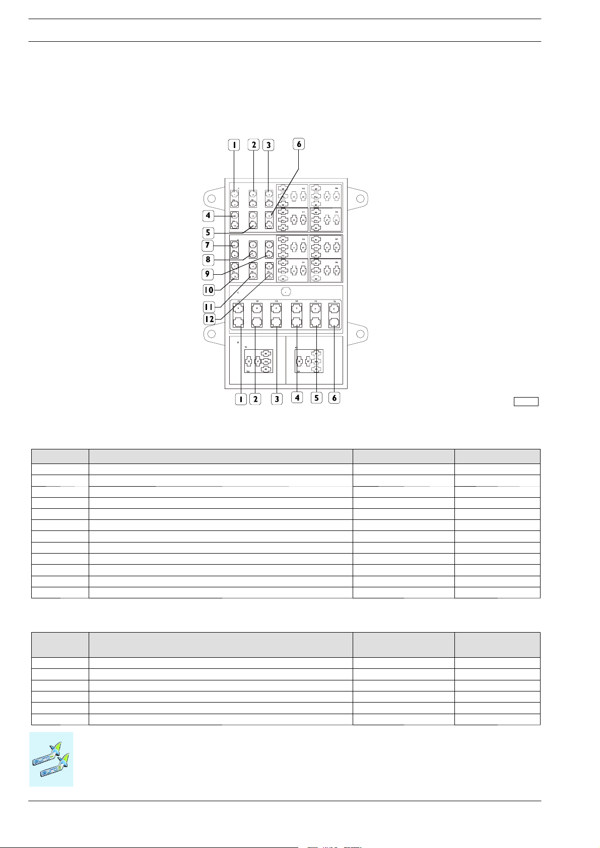
2-58
OPERATIONS ON THE VEHICLE
Fuses and maxi fuses
View of wiring input side
Figure 2.31
M
ASSIF
Table 2.15
Fuse Ref. Use Nominal capacity Name
1 +15 for trailer 15 A AF4
2 - - AF5
3 +15 for blow by heating 7,5 A AF6
4 +15 for debimeter and centre detecting water in diesel filter 10 A AF1
5 +15 for EDC control unit (PIN K-28) 5A AF2
6 EDC control unit power supply 25 A AF3
7 Diesel preheating power supply 10 A BF4
8 Fuel pump power supply 15 A BF5
9 EDC control unit power supply (PIN K-1) 10 A BF6
10 Engine fan (Baruffaldi electromagnetic coupling) 15 A BF1
11 +30 diagnostic connector 5A BF2
12 EDC control unit service power supply 15 A BF3
Table 2.16
Maxi fuses
ref.
Use Nominal capacity Name
1 Differential lock 30 A MF1
2 Trailer control unit 20 A MF2
3 Ignition/startup switch 30 A MF3
4 - - MF4
5 Front-rear windows 40 A MF5
6 ABS 30 A MF6
123908
Electrical System: Modifications and Drawing-Off Power
Base - April 2008 Print 603.93.811
Page 83

MASSIF
Fuse and relay control unit on dashboard
Figure 2.32
OPERATIONS ON THE VEHICLE
2-59
124013
1. Fuse carrier and relay on the dashboard - 2. Fuse box and OBD tap
Electrical System: Modifications and Drawing-Off Power
Print 603.93.811 Base - April 2008
Page 84

2-60
OPERATIONS ON THE VEHICLE
Relays (viewed from wiring input side)
Figure 2.33
M
ASSIF
123907
Table 2.17
Ref. Function Name
1 Maxi key unload relay T21
2 Heated rear window relay T22
3 Power point relay T23
4 Fog lamp relay T24
5 Low beam relay T25
Electrical System: Modifications and Drawing-Off Power
Base - April 2008 Print 603.93.811
Page 85

MASSIF
Fuses (viewed from wiring input side)
Figure 2.34
OPERATIONS ON THE VEHICLE
2-61
Table 2.18
Ref. Use Nominal capacity Name
1 Free - F54
2 Free - F63
3 High beam lights 25 A F56
4 Alarm 10 A F62
5 Door lock 20 A F60
6 Radio/Navigator (+30) 15 A F78
7 Instruments (+ 30) 7,5 A F61
8 Courtesy lights 7,5 A F65
9 Power supply to Right control stalk (+30) 15 A F66
10 Horn/ Hazard lights 15 A F80
11 Brake light circuit 10 A F55
12 Power supply to Left control stalk 10 A F57
13 Rear fog light circuit 10 A F67
14 Reversing light circuit 10 A F69
15 Ignition-operated services 7,5 A F77
16 Free - F79
17 Radio 10 A F58
18 Cigar lighter 10 A F68
19 Power point 20 A F59
20 Heated rear window 15 A F64
Legend for fuse colours:
Red = 10A
Blue = 15A
Yellow = 20A
123906
Electrical System: Modifications and Drawing-Off Power
Print 603.93.811 Base - April 2008
Page 86

2-62
OPERATIONS ON THE VEHICLE
Fuse box and EOBD socket
Front view
Figure 2.35
M
ASSIF
Function
0 OBD tap -
Table 2.19
Fuses Use
Nominal
Capacity
Symbol
1 Left front sidelight/right tail light/left numberplate light 10 A F36
2 Write front sidelight/left t ail light/right n u mberplate light 10 A F34
3 Foglamp 15 A F32
4 Right low beam 10 A F31
5 Left low beam 10 A F30
6 Right high beam 10 A F29
7 Left high beam 10 A F28
8 Interior fan 20 A F26
9 Windscreen wash/wipe and rear window wash/wipe 15 A F24
10 Rear power windows 30 A F22
11 Left front power windows 20 A F20
12 Right front power windows 20 A F18
123910
Electrical System: Modifications and Drawing-Off Power
Base - April 2008 Print 603.93.811
Page 87

MASSIF
OPERATIONS ON THE VEHICLE
2-63
Maxifuse and megafuse fuses
Fuse holder are available at the IVECO shops, to protect high-absorption current drawing.
They shall be positioned (as near the battery drawing terminal as possible) by the body builder depending on the space available
on th e vehicle.
Figure 2.36
119357
Capacity IVECO ref.
no.
KIT 40A 4104 0110 KZ 10 mm
KIT 60A 4104 0111 KZ 10 mm
Cable section Capacity IVECO ref.
no.
2
2
KIT 100A 4104 0112 KZ 25 mm
KIT 125A 4104 0113 KZ 35 mm
KIT 150A 4104 0114 KZ 50 mm
Cable section
2
2
2
It should be pointed out that the current intensity shall, wh en grouping several cables, be reduced compared with the rated value
of one single cable in order to compensate for smaller heat dispersion.
As regards the vehicles the engines of which are frequently started, in the presence of current drawing and short engine rotation
time (e.g. vehicles equipped with refrigerating bodies), the battery shall be recharged at regular intervals in order to ensure efficiency
of the same.
The connections with plugs and terminals shall be of the protected, weather-proof type. Components of the same type as the one
originally fitted to the vehicle shall be used.
In the event th at units and assemblies (various components, etc.) need be relocated due to special body building or vehicle
conversion, such relocation shall be permitted providing:
In the event that a component has be installed just next to the route of a cable belonging to the original system, or a cable route
needs be changed, the same can be relocated provided that its integrity is maintained (cuts shall not be made).
Figure 2.37
Any damage caused by the failure to comply with the procedure shall not be covered by the warranty.
!
Electrical System: Modifications and Drawing-Off Power
Print 603.93.811 Base - April 2008
Page 88

2-64
OPERATIONS ON THE VEHICLE
M
ASSIF
2.16.5 Additional Circuits
These must be separated and protected by a fuse from the vehicle’s main circuit.
The cables utilised must be of a size that is suitable for the relative fun c tions and must be well insulated. They must also be suitable
protected in sheaths (not PVC) or routed though flexible conduits in the case of a plurality of functions (we recommended the u se
of polyamide type 6 plastic for flexible conduits) and they must be correctly installed in a place where they are protected from impact
and heat sources. Take care to avoid any chaffing with other components, particularly with live edges of the bodywork. The transit
of these cables through structural components (cross members, profiles, etc.) must be executed using suitable cable glands or protections; firstly the cables must be secured separately with insulated cable clamps (e.g. made of nylon) at adequate intervals (approx.
200 mm).
In the case of external panels u se a suitable sealant on both the cable and on the panel, to avoid the risk of infiltration of water,
dust, or fumes.
Establish suitable distance between electrical wiring harnesses and other components as follows:
- 10mmfromstaticcomponents;
- 50 mm from moving components (minimum distance = 20 mm);
- 150 mm from components that generate heat (e.g. engine exhaust).
Wherever possible it is good practice to follow a different cable route for signal cables interfering at high absorbed intensity (e.g.
electric motors, solenoid valves) and signals that are susceptible to low absorbed intensities such as sensors, maintaining in an y event
a position as close as possible to the metal structu re of the vehicle in both cases.
Plug and terminal connections must be protected, resistant to weathering, and executed using components of the same type as
those utilised originally on the vehicle.
Use cables and fuses with th e charac teristics shown in the following table in accordance with the current draw:
Table 2.20
Max. continuous current1)(A) Cable cross-section (mm2) Fuse capacity2)(A)
0 ÷ 4 0.5 5
4 ÷ 8 1 10
8 ÷ 16 2.5 20
16 ÷ 25 4 30
25 ÷ 33 6 40
33 ÷ 40 10 50
40 ÷ 60 16 70
60 ÷ 80 25 100
80 ÷ 100 35 125
100 ÷ 140 50 150
1)
Forusesofmorethan30seconds.
2)
Dependingon the positionand hencethe temperature that may be reached in the housing,choose fuses that can be loadedto up to 70% - 80% of their maximum
capacity.
The fuse must be connected as close as possible to the current take-off point.
!
Precautions
- Incorrect installation of electrical accessories may affect occupant safety and cause severe damage to the vehicle.Contact IVECO
if you have any questions.
- Avoid coupling with signal t ransmission cables (e.g. ABS), for which a preferential path has been defined for electromagnetic
requirements (EMI).
It should be noted that when grouping several cables together, in order to compensate for the lower heat dispersal capacity
current intensity must be reduced with respect to the nominal value of a single cable.
- In vehicles subject to frequent engine starts, in the presence of power draws with limited engine running times (e.g. vehicles with
refrigerated bodies) periodic battery charges are required to maintain optimal efficiency.
Electrical System: Modifications and Drawing-Off Power
Base - April 2008 Print 603.93.811
Page 89

MASSIF
OPERATIONS ON THE VEHICLE
2-65
2.16.6 Operations to adjust overhang
If the length of the wires on the chassis are modified to accommodate the new overhang, a watertight joint must be used with
the same specifications as those used on the standard vehicle. Components used - such as wires, connectors, terminals, ducts etc.
- must be the same type as those used originally and must be fitted correctly.
As far as electronic control device function is concerned, no joins are permitted: the cable must be rep laced by a new cable with
the same specifications as that used on the vehic l e, and of appropriate length.
2.16.7 Provision for trailer
If the tail-lights are repeated on the trailer, fit the veh icle with a 13-pin trailer point.
It is not permitted to connect directly to the original equipment tail-light lights. Connection to the original vehicle tail-lights cou ld
cause current overloads that will be indicated by the on-board computer as operating faults.
If it is necessary to make changes to the system other than those described in this manual (e.g. inclusion of LED lights), the operation
must be carried out in conjunction with Iveco.
a) Trailer socket added by the bodybuilder (no parts Kit currently available)
b) Factory-installed trailer connector (optional item 06520)
If the vehicle is ordered complete w ith the trailer connector, the full circuit will be delivered, which is made up of th e electronic
control unit (already fitted into place), the set chassis cable and the 13-pole connector.
Table 2.21
13-pole
connector
Cable no. Description Remarks
pin
1 1120 Rear left indicator bulb 1 bulb (21 W, 12 V)
2 2283 Rear fog light power supply 2bulbs(21W,12V)
3 0000 Ground 4 1125 Rear right indicator bulb 1 bulb (21 W, 12 V)
5 3335
Front left/rear right sidelights;
left lic en ce plate light; left clearance light
1bulb(5W,12V)
6 1175 Brake light power supply 2bulbs(21W,12V)
7 3334
Front right/rear left sidelights;
right licence plate light; right clearance light
1bulb(5W,12V)
8 2268 Reversing light power supply 1 bulb (21 W, 12 V)
9 7777 After fuse F23 on the CVM Battery positive
10 8879 After fuse F16 on the CVM Ignition-operated positive
11 0000 Ground 12 6676 Trailer connection signal (ground)
13 0000 Ground -
Electrical System: Modifications and Drawing-Off Power
Print 603.93.811 Base - April 2008
Page 90

2-66
OPERATIONS ON THE VEHICLE
M
ASSIF
2.16.8 Side Marker Lights
The local or EC standards in force in some countries lay down that the vehicles specially manufactured by the body builders
should be fitted with side marker lights on t he overall length of the vehicle itself.
The external body builders shall take care to make the connections and install the lights on the respective added structures (boxes,
vans, etc.).
Special systems must be used, with relays and protection is appropriately sized in order not to overload the light circuit.
Electrical System: Modifications and Drawing-Off Power
Base - April 2008 Print 603.93.811
Page 91

MASSIF
RepositioningPartsandMountingAuxiliaryAssembliesand Equipment
OPERATIONS ON THE VEHICLE
2-67
2.17 Repositioning Parts and Mounting Auxiliary Assemblies and Equipment
Whenever, in the course of modifying the vehicle, it should become necessary to reposition assemblies such as the fuel tank,
batteries or the spare wheel, such relocation is permitted provided that the functioning of these parts is not impaired and provided
that the same type of connections as originally in use are re-employed. Their transversal location on the vehicle’s chassis may not,
when their weight requires it, be changed radically.
Spare wheel carrier
In the case of chassis cabs not equipped with a spare wheel carrier, and vehicles in which the spare wheel carrier must be
relocated, the spare wheel must be set on a support of suitable size that allows the wheel to be readily removed.
In order to limit the torsional stresses on the vehicle chassis, we recommend that the plate be fitted where there is a cross
member, particularly in the case of heavy units.
A similar procedure should be adopted when fitting additional u nits such as tanks, compressors etc. When positioning them, due
consideration must be given to the distribution of the weights (see point 1.13). Adequate ground clearance must be ensured with
due con sideration given to the operation of the vehicle.
Any new holes that are necessary for the relocation must be made in the web of the sidemember in accordance with the
specifications given in point 2.3 taking care to use existing holes as much as possible.
Fuel tank
Figure 2.38
121878
The use of fuel tanks o ther t han the original tanks will lead to incorrect readings for fuel reserve, fuel consumption, range etc.
on the control panel.
The new electrical systems architecture will process the fuel gauge level signals by associating the emptying concept as for the fuel
tank original fitted.
Fuel tanks are subjected to homologation.
!
Repositioning Parts and Mounting Auxiliary Assemblies and Equipment
Print 603.93.811 Base - April 2008
Page 92

2-68
OPERATIONS ON THE VEHICLE
Retarde rI nstall ation
M
ASSIF
2.18 Retarder Installation
Not applicable to the vehicle.
2.19 Modifications to the Rear Underrun
Our vehicles are fitted with a rear underrun bar in accordance with EC Directives.
The maximum permitted distance from the bar to the rearmost part of the body is 450 mm, deducting the distortion found during
approval tests (10 mm on average).
Whenever the chassis modifications affect the rear overhang, the underrun bar must be repositioned (in compliance with current
regulations) keeping the same connection with the chassis as the original vehicle.
When modifying th e vehicles or installing special equipment (e.g. tail lifts) it may be necessary to modify the structure of the underrun
bar. Such modifications must not change the original resistance and stiffness specifications (so as to comply with local government
regulations, if any). The company carrying out the modification / installation must where required, submit the necessary document
demonstrating compliance with legislation in force at th e time.
In the event that a different under run-bar has to be fitted, compliance with the standards and regulations in force must be checked.
Test certificates and documentation must, where required, be submitted to the respective government agency .
2.20 Rear mudguards and wheel boxes
When vehicles are supplied without mudguards, the bodybuilder must fit them using similar
installations as u sed by IVECO on similar vehicles. In making the mudguards, wheel arch es, as well as the shape of the body, bear
in mind that:
- Ensure the wheels can turn even in the full bump condition with snow chains fitted, in compliance with the limits shown in the
documentation supplied by IVECO.
- The maximum width of the vehicle over the tyres must comply with the legal limits.
- The supporting structure should be su fficiently stron g enough , avoiding any sudden variation in sect ion .
The instructions given in the first two steps shall also be followed when wheelboxes have to be executed.
2.21 Mudflaps
If legally required, un less already fitted ex-factory, the bodybuilder must ensure that the complete vehicle is fitted with mud flaps.
When fitting these all regulations (e.g. dimensional etc) must be complied with.
Retarder Installation
Base - April 2008 Print 603.93.811
Page 93

MASSIF
SideGuards
OPERATIONS ON THE VEHICLE
2.22 Side Guards
Not applicable.
Chocks
2.23 Chocks
Bodybuilders must t ake care to identify an arrangement t hat complies with local regulations. The new positioning must offer
characteristics of reliability and safety and also be easily accessible for operation by the user.
2-69
Side Guards
Print 603.93.811 Base - April 2008
Page 94

2-70
OPERATIONS ON THE VEHICLE
M
ASSIF
Chocks
Base - April 2008 Print 603.93.811
Page 95

MASSIF
Index
FITTING SUPERSCTRUCTURES
SECTION 3
Fitting supersctructures
3.1 Construction of t he Subframe 3-3
3.1.1 Material 3-3
3.1.2 Section bar dimensions 3-4
3.1.3 Aluminium Subframe 3-5
3.2 Elements making up the subframe 3-6
3.2.1 Longitudinal Runner Profiles 3-6
3.2.2 Cross Members 3-8
3-1
Page
3.3 Connections between frame and counterframe 3-10
3.3.1 Choosing the Type of Body Mounting 3-10
3.3.2 Body Mounting Characteristics 3-10
3.3.3 Connection with Brac k ets 3-11
3.3.4 Elastic connections 3-11
3.3.5 Connection with U-bolts (clamps) 3-12
3.3.6 Connection with Plates for Longitudinal and Transverse Fixing (rigid type) 3-13
3.4 Fitting Box Bodies 3-14
3.4.1 Fixed boxes 3-14
3.4.2 Tipper boxes 3-14
3.5 Tractor for half-trailers 3-15
3.6 Transport of Indivisible Materials 3-15
3.7 Installation of Tanks and Containers for Bulk Materials 3-15
3.8 Installation of cranes 3-15
3.8.1 Crane Behind the Driver’s Cab 3-15
3.9 Installation of Tail Lifts 3-15
3.10 Recovery Vehicles 3-15
3.11 Municipal, Fire-fighting an d Special Services 3-15
3.12 Installation of front snowploughs 3-16
Index
Print 603.93.811 Base - April 2008
Page 96

3-2
FITTING SUPERSCTRUCTURES
M
ASSIF
Page
3.13 Winch Installati on 3-16
3.14 Special body conversions 3-16
3.14.1 Installing an aerial platform 3-16
Index
Base - April 2008 Print 603.93.811
Page 97

MASSIF
360(1)235(1)25%(1
)
53042021%
52036022%
33333.
Constructi on ofthe Su bframe
FITTING SUPERSCTRUCTURES
3-3
NOTE
The following general instructions complement the general instructions given in the general regulations in Chapter 1.
3.1 Construction of the Subframe
The purpose of an subframe (auxiliary frame) is to ensure a uniform distribution of the load on the vehicle’s chassis and to increase
the strength and rigidity of the main frame in relation to the particular use of the vehicle.
The following points are to be borne in mind when constructing a subframe:
3.1.1 Material
Usually, provided the subframe is not to undergo great stress, the material used for its construction may be of a lower grade
than that used for the vehicle chassis. It shall have good weldability ch aracteristics an d limits not lower t han valoes (1) shown in
Table 3.1.
Should the stress limits require it (e.g. crane applications), or if very high sections are to be avoided, material with better mechanical
characteristics may be used. In this case it should be considered that a lower inertia moment of the reinforcing beam implies high
bending stresses on the chassis frame.
The properties of c ertain materials that are considered in some of the applications indicated below are as follows.
Table 3.1 - Material to be used for body manufacturing Standard IVECO 15-2110 and 15-2812
Steel name
IVECO FE360D
EUROPE S235JR
GERMANY S235JR
UK 37/23CR
IVECO FEE420
EUROPE S420MC
GERMANY S420MC
UK S420MC
IVECO FE510D
EUROPE S355J2G3F
GERMANY S355J2G3F
UK 50D
Breaking load
(N/mm
2
)
Yield point
(N/mm
2
)
Elongation A5
Construction of the Subframe
Print 603.93.811 Base - April 2008
Page 98

3-4
FITTING SUPERSCTRUCTURES
3.1.2 Section bar dimensions
M
ASSIF
The table below illustrates the values for the bulk modulus Wxfor C-section bars recommended by IVECO. The indicated W
value refers to the real section and allows for the section bar c o u pling radii (it c an be calculated with some approximation by multiplying by 0.95 the value obtained by considering the section made up of simple rectangles). Bars of different sections can be used as
replacements for the indicated ones, provided that the bulk modulus W
and the moment of inertia Jxof the new C-section do
x
not features smaller values.
Table 3.2 - Profiles recommended by IVECO
Strength modulus
Wx (cm
3
)
Recommended C-section profile
(mm)
16 ≤ W ≤ 19 80 X 50 X 4 80 X 60 X 4 80 X 50 X 5
20 ≤ W ≤ 23 80 X 60 X 5
24 ≤ W ≤ 26 80 X 60 X 6
27 ≤ W ≤ 30 80 X 60 X 7 100 X 50 X 5
31 ≤ W≤ 33 80 X 60 X 8 100 X 60 X 5
34 ≤ W ≤ 36 100 X 60 X 6
37 ≤ W ≤ 41 100 X 60 X 7
42 ≤ W ≤ 45 80 X 80 X 8 100 X 60 X 8
46 ≤ W ≤ 52 120 X 60 X 6 120 X 60 X 7
53 ≤ W ≤ 58 120 X 60 X 8
59 ≤ W ≤ 65 140 X 60 X 7 120 X 70 X 7
66 ≤ W ≤ 72 140 X 60 X 8 120 X 80 X 8
73 ≤ W≤ 79 160 X 60 X 7
80 ≤ W ≤ 88 180 X 60 X 8
89 ≤ W ≤ 93 160 X 70 X 7 180 X 60 X 7 140 X 80 X 8
94 ≤ W ≤ 104 180 X 60 X 8
105 ≤ W ≤ 122 200 X 80 X 6 200 X 60 X 8 180 X 70 X 7
123 ≤ W ≤ 126 220 X 60 X 7
127 ≤ W≤ 141 220 X 60 X 8
142 ≤ W ≤ 160 200 X 80 X 8 240 X 60 X 8
161 ≤ W ≤ 178 220 X 80 X 8 240 X 70 X 8
179 ≤ W ≤ 201 250 X 80 X 7 260 X 70 X 8
202 ≤ W ≤ 220 250 X 80 X 8 260 X 80 X 8
221 ≤ W ≤ 224 220 X 80 X 8 280 X 70 X 8
225 ≤ W ≤ 245 250 X 100 X 8 280 X 80 X 8
246 ≤ W ≤ 286 280 X 100 X 8
290 ≤ W ≤ 316 300 X 80 X 8
316 ≤ W ≤ 380 340 X 100 X 8
440 380 X 100 X 8
480 400 X 100 X 8
x
Construction of the Subframe
Base - April 2008 Print 603.93.811
Page 99

MASSIF
FITTING SUPERSCTRUCTURES
3-5
3.1.3 Aluminium Subframe
In the case of materials, having different characteristics compared to steel, such as aluminium, both the dimensions and the struc-
tures of the subframe will have, as a rule, to be adapted accordingly.
When the subframe’s main function is mainly to distribute t he load more evenly while leaving the major loadbearing to the frame,
aluminium longitudinal runners can be used having the same dimensions as stated for the steel. Some typical examples are: fixed
bodies, vans, tanks with continuous and close spaced bearers or bearers mounted directly over the suspension h anger brackets.
Exceptionsare those cases where the high stresses on the vehicle’s frame demand steel runners of a high dimension or shear-resistant
connections.
When the subframe must contribute in terms of strength and stiffness (bodies having high concentrated loads, such as tippers, cranes,
central axle trailers, etc.) aluminium is not recommended and has therefore to be authorised for each application.
It should be remembered that, when stating the minimum dimensions for the reinforcement runners, besides the admitted limit of
stress for the aluminium, the different elastic modulus compared to steel (approx. 7,000 kg/mm
will also have to be considered. This will result in larger dimensions for the runners.
Similarly, when the connection between frame and counterframe guarantees the transmission of shearing forces (connection via
plates), a new neutral axis must be defined for the section based on the different elastic coefficients of both materials when checking
the stresses at both ends of the single section.
The cooperation request for aluminium definitely means dimensions that are too large and not good value.
2
as against 21,000 kg/mm2for steel)
Construction of the Subframe
Print 603.93.811 Base - April 2008
Page 100

3-6
FITTING SUPERSCTRUCTURES
Elementsmakingup the s ubfr ame
M
ASSIF
3.2 Elements making up the subframe
3.2.1 Longitudinal Runner Profiles
The side member of the added structure must be continuous, extending as far as possible forward to the front of the vehicle
to include, if possible, the area of the rear support of the front spring, and rest on the chassis of the vehicle but not on the brackets.
In order to achieve a gradual reduction in the resistant section, the front ends of the longitudinal runner must be tapered upwards
at an angle of no more than 30°, or tapered in some other equivalent way (see Figure 3.1), ensuring that the front end in contact
with the chassis is suitably connected, min radius 5 mm.
Figure 3.1
91136
If rear cab suspension components (e.g. with long cabs) do n ot allow the full section cross-section to pass through, proceed as
shown in Figure 3.2. This could require the minimum resistant cross-section to be checked when high front bending moments are
present (e.g. with a crane behind the cab that is operating towards the front of the vehicle) and the fastening should not be more
than 250 mm away from the front end of the subframe if possible.
Figure 3.2
102455
Elements making up the subframe
Base - April 2008 Print 603.93.811
 Loading...