


.. inter
MCS® -80/85 FAMILY
USER'SMANUAL
Jan uary 1983 .
Intel Corporation makes no warranty for the use of its products and assumes no responsibility for any errors which may appear in this document nor does it make a commitment to update the information contained herein.
The following are trademarks of Intel Corporation and may only be used to identify Intel Products:
2
BXP, CREDIT, i, ICE, 1 -ICE, iCS, iLBX,i m, iMMX, Insite, INTEL, intel, Intelevision, Intellec, inteligent IdentifierTM, inteligent Programming™, Intellink, iOSP, iPDS, iRMS, iSBC,
iSBX, iSXM, Library Manager, MCS, Megachassis, Micromainframe, MULTIBUS, Multichannel™ Plug-A-Bubble, MULTIMODULE, PROMPT, Promware, RMXJ80, RUPI, System 2000, and UPI, and the combination of ICE, iCS, iRMX, iSBC, MCS, or UPI and a numerical suffix.
MDS is an ordering code only and is not used as a product name or trademark. MDS® is a registered trademark of Mohawk Data Sciences Corporation.
* MULTIBUS is a patented Intel bus.
Additional copies of this manual or other Intel literature may be obtained from:
Intel Corporation
Literature Department
3065 Bowers Avenue
Santa Clara, CA 95051
©INTEl CORPORATION, 1982

Table of Contents
CHAPTER 1 |
|
Part 1: Introduction to the Functions of a Computer ................................... |
1-1 |
Part 2. Introduction to MCS®-85 ..................................................... |
1-6 |
CHAPTER 2 |
|
Functional Description .............................................................. |
2-1 |
CHAPTER 3 |
|
System Operation and Interfacing .................................................... |
3-1 |
CHAPTER 4 |
|
The 8080 Central Processor Unit ..................................................... |
4-1 |
CHAPTER 5 |
|
The Instruction Set ................................................................. |
5-1 |
Instruction Set Index ................................................................ |
5-19 |
*CHAPTER 6 |
|
Device Specifications |
|
8080A/8080A-1 /8080A-2 8-Bit N-Chcimnel Microprocessor. . . . . . . . . . . . . . . . . . . . . . . . . . .. |
6-1 |
8085AH/8085AH-2/8085AH-1 8-Bit HMOS Microprocessors .......................... |
6-10 |
8085A/8085A-2 Single Chip 8-Bit N-Channel Microprocessors ....................... |
6-26 |
APPENDIX |
|
Applications of MCS®-85 ............................................................ |
A1-1 |
WORKSHOPS
* For complete data sheets on all microprocessor and peripheral products, refer to the Microprocessor and Peripherals Handbook. See inside front cover to order.
iii

Introduction
CHAPTER 1
PART 1: INTRODUCTION TO THE FUNCTIONS OF A COMPUTER
This chapter introduces certain basic computer concepts. It provides background information and definitions which will be useful in later chapters of this manual. Those already familiar with computers may skip this material, at their option.
A TYPICAL COMPUTER SYSTEM
A typical digital computer consists of:
a)A central processor unit (CPU)
b)A memory
c)Input/output (I/O) ports
The memory serves as a place to store Instructions, the coded pieces of information that direct the activities of the CPU, and Data, the coded pieces of information that are processed by the CPU. A group of logically related instructions stored in memory is referred to as a Program. The CPU "reads" each instruction from memory in a logically determined sequence, and uses it to initiate processing actions. If the program sequence is coherent and logical, processing the program will produce intelligible and useful results.
The memory is also used to store the data to be manipulated, as well as the instructions that direct that manipulation. The program must be organized such that the CPU does not read a non-instruction word when it expects to see an instruction. The CPU can rapidly access any data stored in memory; but often the memory is not large enough to store the entire data bank required for a particular application. The problem can be resolved by providing the computer with one or more Input Ports. The CPU can address these ports and input the data contained there. The addition of input ports enables the computer to receive information from external equipment (such as a paper tape reader or floppy disk) at high rates of speed and in large volumes.
A computer also requires one or more Output Ports that permit the CPU to communicate the result of its processing to the outside world. The output may go to a display, for use by a human operator, to a peripheral device that produces "hard-copy," such as a line-printer, to a
peripheral storage device, such as a floppy disk unit, or the output may constitute process control signals that direct the operations of another system, such as an automated assembly line. Like input ports, output ports are addressable. The input and output ports together permit the processor to communicate with the outside world.
The CPU unifies the system. It controls the functions performed by the other components. The CPU must be able to fetch instructions from memory, decode their binary contents and execute them. It must also be able to reference memory and I/O ports as necessary in the execution of instructions. In addition, the CPU should be able to recognize and respond to certain external control signals, such as INTERRUPT and WAIT requests. The functional units within a CPU that enable it to perform these functions are described below.
THE ARCHITECTURE OF A CPU
A typical central processor unit (CPU) consists of the following interconnected functional units:
•Registers
•Arithmetic/Logic Unit (ALU)
•Control Circuitry
Registers are temporary storage units within the CPU. Some registers, such as the program counter and instruction register, have dedicated uses. Other registers, such as the accumulator, are for more general purpose use.
Accumu lator:
The accumulator usually stores one of the operands to be manipulated by the ALU. A typical instruction might direct the ALU to add the contents of some other register to the contents of the accumulator and store the result in the accumulator itself. In general, the accumulator is both a source (operand) and a destination (result) register.
Often a CPU will include a number of additional general purpose registers that can be used to store operands or intermediate data. The availabil ity of general purpose
1-1
registers eliminates the need to "shuffle" intermediate results back and forth between memory and the accumulator, thus improving processing speed and efficiency.
Program Counter (Jumps, Subroutines
and the Stack):
The instructions that make up a program are stored in the system's memory. The central processor references the contents of memory, in order to determine what action is appropriate. This means that the processor must know which location contains the next instruction.
Each of the locations in memory is numbered, to distinguish it from all other locations in memory. The number which identifies a memory location is called its Address.
The processor maintains a counter which contains the address of the next program instruction. This register is called the Program Counter. The processor updates the program counter by adding "1" to the counter each time it fetches an instruction, so that the program counter is always current (pointing to the next instruction).
The programmer therefore stores his instructions in numerically adjacent addresses, so that the lower addresses contain the first instructions to be executed and the higher addresses contain later instructions. The only time the programmer may violate this sequential rule is when an instruction in one section of memory is a Jump instruction to another section of memory.
A jump instruction contains the address of the instruction which is to follow it_ The next instruction may be stored in any memory location, as long as the programmed jump specifies the correct address. During the execution of a jump instruction, the processor replaces the contents of its program counter with the address embodied in the Jump. Thus, the logical continuity of the program is maintained.
A special kind of program jump occurs when the stored program "Calls" a subroutine. In this kind of jump, the processor is required to "remember" the contents of the program counter at the time that the jump occurs. This enables the processor to resume execution of the main program when it is finished with the last instruction of the subroutine.
A Subroutine is a program within a program. Usually it is a general-purpose set of instructions that must be executed repeatedly in the course of a main program. Routines which calculate the square, the sine, or the logarithm of a program variable are good examples of functions often written as subroutines. Other examples might be programs designed for inputting or outputting data to a particular peripheral device.
The processor has a special way of handling subroutines, in order to insure an orderly return to the main program. When the processor receives a Call instruction, it increments the Program Counter and stores the counter's contents in a reserved memory area known as the Stack. The Stack thus saves the address of the instruction to be executed after the subroutine is completed. Then the pro-
cessor loads the address specified in the Call into its Program Counter. The next instruction fetched will therefore be the first step of the subroutine.
The last instruction in any subroutine is a Return. Such an instruction need specify no address. When the processor fetches a Return instruction, it simply replaces the current contents of the Program Counter with the address on the top of the stack. This causes the processor to resume execution of the calling program at the point immediately foLlowing the original Call Instruction.
Subroutines are often Nested; that is, one subroutine will sometimes call a second subroutine. The second may call a third, and so on. This is perfectly acceptable, as long as the processor has enough capacity to store the necessary return addresses, and the logical provision for doing so. In other words, the maximum depth of nesting is determined by the depth of the stack itself. If the stack has space for storing three return addresses, then three levels of subroutines may be accommodated.
Processors have different ways of maintaining stacks. Some have facilities for the storage of return addresses built into the processor itself_ Other processors use a reserved area of external memory as the stack and simply maintain a Pointer register which contains the address of the most recent stack entry. The external stack allows virtually unlimited subroutine nesting. In addition, if the processor provides instructions that cause the contents of the accumulator and other general purpose registers to be "pushed" onto the stack or "popped" off the stack via the address stored in the stack pointer, multi-level interrupt processing (described later in this chapter) is possible. The status of the processor (i.e., the contents of all the registers) can be saved in the stack when an interrupt is accepted and then restored after the interrupt has been serviced. This ability to save the processor's status at any given time is possible even if an interrupt service routine, itself, is interrupted.
Instruction Register and Decoder:
Every computer has a Word Length that is characteristic of that machine. A computer's word length is usually determined by the size of its internal storage elements and interconnecting paths (referred to as Busses); for example, a computer whose registers and busses can store and transfer 8 bits of information has a characteristic word length of 8-bits and is referred to as an 8-bit parallel processor. An eight-bit parallel processor generally finds it most efficient to deal with eight-bit binary fields, and the memory associated with such a processor is therefore organized to store eight bits in each addressable memory location. Data and instructions are stored in memory as eight-bit binary numbers, or as numbers that are integral multiples of eight bits: 16 bits, 24 bits, and so on. This characteristic eight-bit field is often referred to as a Byte.
Each operation that the processor can perform is identified by a unique byte of data known as an Instruction
1-2
Code or Operation Code. An eight-bit word used as an instruction code can distinguish between 256 alternative actions, more than adequate for most processors.
The processor fetches an instruction in two distinct operations. First, the processor transmits the address in its Program Counter to the memory. Then the memory returns the addressed byte to the processor. The CPU stores this instruction byte in a register known as the Instruction Register, and uses it to direct activities during the remainder of the instruction execution.
The mechanism by which the processor translates an instruction code into specific processing actions requires more elaboration than we can here afford. The concept, however, should be intuitively clear to any logic designer. The eight bits stored in the instruction register can be decoded and used to selectively activate one of a number of output lines, in this case up to 256 lines. Each line represents a set of activities associated with execution of a particular instruction code. The enabled line can be combined with selected timing pulses, to develop electrical signals that can then be used to initiate specific actions. This translation of code into action is performed by the Instruction Decoder and by the associated control circu itry.
An eight-bit instruction code is often sufficient to specify a particular processing action. There are times, however, when execution of the instruction requires more information than eight bits can convey.
One example of this is when the instruction references a memory location. The basic instruction code identifies the operation to be performed, but cannot specify the object address as well. In a case like this, a twoor threebyte instruction must be used. Successive instruction bytes are stored in sequentially adjacent memory locations, and the processor performs two or three fetches in succession to obtain the full instruction. The first byte retrieved from memory is placed in the processor's instruction register, and subsequent bytes are placed in temporary storage; the processor then proceeds with the execution phase. Such an instruction is referred to as Variable Length.
Address Register(s):
A CPU may use a register or register-pair to hold the address of a memory location that is to be accessed for data. If the address register is Programmable, (i.e., if there are instructions that allow the programmer to alter the contents of the register) the program can "build" an address in the address register prior to executing a Memory Reference instruction (i.e., an instruction that reads data from memory, writes data to memory or operates on data stored in memory).
Arithmetic/Logic Unit (ALU):
All processors contain an arithmetic/logic unit, which is often referred to simply as the ALU. The ALU, as its name implies, is that portion of the CPU hardware which
performs the arithmetic and logical operations on the binary data.
The ALU must contain an Adder which is capable of combining the contents of two registers in accordance with the logic of binary arithmetic. This provision permits the processor to perform arithmetic manipulations on the data it obtains from memory and from its other inputs.
Using only the basic adder a capable programmer can write routines which will subtract, multiply and divide, giving the machine complete arithmetic capabilities. In practice, however, most ALUs provide other built-in functions, including hardware subtraction, boolean logic operations, and shift capabilities.
The ALU cqntains Flag Bits which specify certain conditions that arise in the course of arithmetic and logical manipulations. Flags typically include Carry, Zero, Sign, and Parity. It is possible to program jumps which are conditionally dependent on the status of one or more flags. Thus, for example, the program may be designed to jump to a special routine if the carry bit is set following an addition instruction.
Control Circuitry:
The· control circuitry is the primary functional unit within a. CPU. Using clock inputs, the control circuitry 'maintains the proper sequence of events required for any processing task. After an instruction is fetched and decoded, the control circuitry issues the appropriate signals (to units both internal and external to the CPU) for initiating the proper processing action. Often the control circuitry will be capable of responding to external signals, such as an interrupt or wait request. An Interrupt request will cause the control circuitry to temporarily interrupt main program execution, jump to a special routine to service the interrupting device, then automatically return to the main program. A Wait request is often issued by a memory or I/O element that operates slower than the CPU. The control circuitry will idle the CPU until the memory or I/O port is ready with the data.
COMPUTER OPERATIONS
There are certain operations that are basic to almost any computer. A sound understanding of these basic operations is a necessary prerequisite to examining the specific operations of a particular computer.
Timing:
The activities of the central processor are cycl ical. The processor fetches an instruction, performs the operations required, fetches the next instruction, and so on. This orderly sequence of events requires precise timing, and the CPU therefore requires a free running oscillator clock which furnishes the reference for all processor actions. The combined fetch and execution of a single instruction is referred to as an Instruction Cycle. The portion of a cycle identified
1-3
with a clearly defined activity IS called a State. And the interval between pulses of the timing oscillator is referred to as a Clock Period. As a general rule, one or more clock periods are necessary for the completion of a state, and there are several states in a cycle.
Instruction Fetch:
The first state(s) of any instruction cycle will be dedicated to fetching the next instruction. The CPU issues a read signal and the contents of the program counter are sent to memory, which responds by returning the next instruction word. The first byte of the instruction is placed in the instruction register. If the instruction consists of more than one byte, additional states are required to fetch each byte of the instruction. When the entire instruction is present in the CPU, the program counter is incremented (in preparation for the next instruction fetch) and the instruction is decoded. The operation specified in the instruction will be executed in the remaining states of the instruction cycle. The instruction may call for a memory read or write, an input or output and/or an internal CPU operation, such as a register-to-register transfer or an add-registers operation.
Memory Read:
An instruction fetch is merely a special memory read operation that brings the instruction to the CPU's instruction register. The instruction fetched may then call for data to be read from memory into the CPU. The CPU again issues a read signal and sends the proper memory address; memory responds by returning the requested word. The data received is placed in the accumulator or one of the other general purpose registers (not the instruction register).
Memory Write:
A memory write operation is similar to a read except for the direction of data flow. The CPU issues a write signal, sends the proper memory address, then s~nds the data word to be written into the addressed memory location.
Wait (memory synchronization):
As previously stated, the activities of the processor are timed by a master clock oscillator. The clock period determines the timing of all processing activity.
The speed of the processing cycle, however, is limited by the memory's Access Time. Once the processor has sent a read address to memory, it cannot proceed until the memory has had time to respond. Most memories are capable of responding much faster than the processing cycle requires. A few, however, cannot supply the addressed byte within the minimum time established by the processor's clock.
Therefore a processor should contain a synchronization provision, which permits the memory to request a Wait state. When the memory receives a read or write enable ~ig nal, it places a request signal on the processor'sR EADY f.ine, causing the CPU to idle temporarily. After the memory has
had time to respond, it frees the processor's READY line, and the instruction cycle proceeds.
Input/Output:
InpLJt and Output operations are similar to memory read and write operations with the exception that a peripherall/O device is addressed instead of a memory location. The CPU issues the appropriate input or outppt control signal, sends the proper device address and either receives the data being input or sends the data to be output.
Data can be input/output in either parallel or serial form. All data within a digital computer is represented in binary coded form. A binary data word consists of a group of bits; each bit is either a one or a zero. Parallel I/O consists of transferring all bits in the word at the same time, one bit per line. Serial I/O consists of transferring one bit at a time on a single line. Naturally serial I/O is much slower, but it requires considerably less hardware than does parallel I/O.
Interrupts:
Interrupt provisions are included on many central processors, as a means of improving the processor's efficiency. Consider the case of a computer that is processing a large volume of data, portions of which are to be output to a printer. The CPU can output a byte of data within a single machine cycle but it may take the printer the equivalent of many machine cycles to actually print the character specified by the data byte. The CPU could then remain idle waiting until the printer can accept the next data byte. If an interrupt capability is implemented on the computer, the CPU can output a data byte then return to data processing. When the printer is ready to accept the next data byte, it can request an interrupt. When the CPU acknowledges the interrupt, it suspends main program execution and automatically branches to a routine that will output the next data byte. After the byte is output, the CPU continues with main program execution. Note that this is, in principle, quite similar to a SUbroutine call, except that the jump is initiated externally rather than by the program.
More complex interrupt structures are possible, in which several interrupting devices share the same processor but have different priority levels. Interruptive processing is an important feature that enables maximum untilization of a processor's capacity for high system throughput.
Hold:
Another important feature that improves the throughput of a processor is the Hold. The hold provision enables Direct Memory Access (DMA) operations.
In ordinary input and output operations, the processor itself supervises the entire data transfer. Information to be placed in memory is transferred from the input device to the processor, and then from the processor to the designated memory location. In similar fashion, information that goes
1-4

from memory to output devices goes by way of the processor.
Some peripheral devices, however, are capable of transferring information to and from memory much faster than the processor itself can accomplish the transfer. If any appreciable quantity of data must be transferred to or from such a device, then system throughput will be increased by
having the device accomplish the transfer directly. The pro· cessor must temporarily suspend its operation during such a transfer, to prevent conflicts that would arise if processor and peripheral device attempted to access memory simul· taneously. It is for this reason that a hold provision is in· cluded on some processors.
CPU
MODULE
1·5

PART 2: INTRODUCTION TO MCS-85™
THE MCS·SS™ MICROCOMPUTER
SYSTEM
The basic philosophy behind the MCS·85 microcomputer system is one of logical, evolutionary advance in technology without the waste of discarding existing investments in hardware and software. The MCS-85 provides the existing 8080 user with an increase in performance, a decrease in the component count, operation from a single 5-Volt power supply, and still preserves 100% of his existing software investment. For the'new microcomputer user, the MCS-85 represents the refinement of the most popular microcomputer in the industry, the Intel 8080, along with a wealth of supporting software, documentation and peripheral components to speed the cycle from prototype to production. The same development tools that Intel has produced to support the 8080 microcomputer system can be used for the MCS-85, and additional add-on features are available to optimize system development for
MCS-85~
This section of the MCS-80/85 User'sManual will briefly detail the basic differences between the MCS-85 and MCS-80 families. It will illustrate both the hardware and software compatibilities and also reveal some of the engineering trade-ofts that were met during the design 'of the MCS-85. More detailed discussion of the MCS-85 bus operation and component specifications are available in Chapters: 2, 3, 4, and 5. The information provided in Chapter 1 will be helpful in understanding the basic concepts and philosophies behind the MCS-85.
EVOLUTION
In December 1971, Intel introduced the first general purpose, 8-bit microprocessor, the 8008. It was implemented in P-channel MOS technology and was packaged in a single 18 pin, dual in-line package (DIP). The 8008 used standard semiconductor ROM and RAM and, for the most part, TTL components for I/O and general interface. It immediately found applications in byte-oriented end products such as terminals and computer peripherals where its instruction execution (20 micro·seconds),general
60
1\
\8080
30 |
|
|
~ |
|
|
|
|
|
|
|
|
|
||
|
|
|
|
~ |
80SOA |
|
8080A AND |
|||||||
|
|
|
|
|
||||||||||
15 |
|
|
|
|
|
|
|
|
"- |
PERIPHERALS |
||||
|
|
|
|
|
|
|
|
|
|
|||||
3 |
|
|
|
|
|
|
|
|
|
|
\ |
|
8085 |
|
1 |
|
|
|
|
|
|
|
|
|
|
|
|
|
|
|
|
|
|
|
|
|
|
|
|
|
|
|
|
|
1971 |
1972 |
1973 |
1974 |
1975 |
1976 |
|
1977 |
|||||||
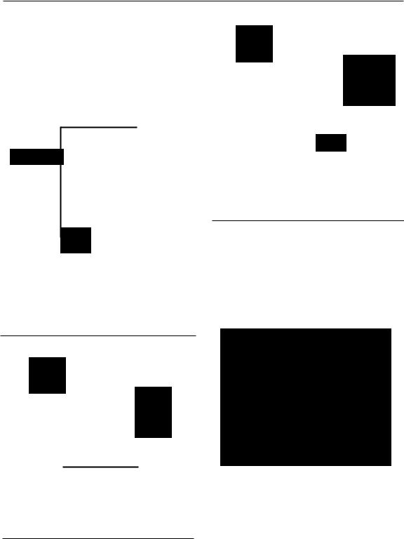
8-BIT SMALL SYSTEM COMPONENT COUNT 1971 - 1977
1·6

INTRODUCTION TO MCS-85™
purpose organization and instruction set matched the requirements of these products. Recognizing that hardware was but a small part in the overall system picture, Intel developed both hardware and software tools for the design engineer so that the transition from prototype to production would be as simple and fast as possible. The commitment of providing a total systems approach with the 8008 microcomputer system was actually the basis for the sophisticated, comprehensive development tools that Intel has available today.
THE 8080A MICROPROCESSOR
With the advent of high-production N-channel RAM memories and 40 pin DIP packaging, Intel designed the 8080A microprocessor. It was designed to be software compatible with the 8008 so that the existing users of the 8008 could preserve their investment in software and at the same time provide dramatically increased performance (2 micro-second instruction execution), while reducing the amount of components necessary to implement a system. Additions were made to the basic instruction set to take advantage of this increased performance and large system-type features were included onchip such as DMA, 16-bit addressing and external stack memory so that the total spectrum of application could be significantly increased. The 8080 was first sampled in December 1973. Since that time it has become the standard of the industry and is accepted as the primary building block for more microcomputer based applications than all other microcomputer systems combined.
A TOTAL SYSTEMS COMMITMENT
The Intel® 8080A Microcomputer System encompasses a total systems commitment to the user to fully support his needs both in developing prototype systems and reliable, high volume production. From complex MOS/LSI peripheral components to resident high level systems language (PUM) the Intel® 8080 Microcomputer System provides the most comprehensive, effective solution to today'ssystem problems.
20 |
|
|
|
|
|
|
|
|
|
|
|
|
|
|
|
1510 |
|
|
|
|
|
|
|
|
|
|
|
|
|
|
|
~\ |
|
|
|
|
|
|
|
|
|
|
|
|
|
|
|
|
rl |
|
|
|
|
|
|
|
|
|
::: |
||||
|
|
|
|
|
|
|
|
|
|
|
|
|
|
|
|
|
|
|
|
|
|
|
|
|
|
|
|
|
|
|
|
|
r |
\ |
|
|
|
|
|
|
|
|
|
|
|
|
|
|
|
l |
|
|
|
|
|
|
|
|
|
|
|||
|
|
|
|
|
|
|
|
|
|
|
|
||||
|
|
\ |
|
|
|
|
|
|
|
|
|
|
|
|
|
|
|
\ |
|
|
|
|
|
|
|
|
|
|
|
||
o |
|
|
|
|
|
|
|
|
|
|
|
|
|
-- |
|
1 |
r |
|
|
|
|
|
|
|
|
|
|
|
|
|
|
|
|
|
|
|
|
|
|
|
|
|
|
|
|
||
|
|
|
|
|
|
|
|
|
|
|
|
|
|
|
|
|
|
|
|
|
|
|
|
|
|
|
|
|
|
|
|
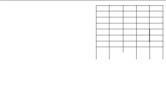
1973 |
1974 |
1975 |
1976 |
1977 |
1978 |
||||||||||
|
|
|
|
|
|
|
YEAR |
|
|
|
|
|
|
||
PROTOTYPE |
|
PRODUCTION |
|
||
|
|
|
1-7

INTRODUCTION TO MCS-85™
SOFTWARE COMPATIBILITY
As with any computer system the cost of software development far outweighs that of hardware. A microcomputer-based system is traditionally a very cost-sensitive application and the development of software is one of the key areas where success or failure of the cost objectives is vital.
8080A |
|
808SA |
PROGRAMS |
|
SYSTEM |
|
||
|
|
|
The 8085A CPU is 100% software compatible with the Intel® 8080A CPU. The compatibility is at the object or "machine code" level so that existing programs written for 8080A execution will run on the 8085A as is. The value of this becomes even more evident to the user who has mask programmed ROMs and wishes to update his system without the need for new masks.
PROGRAMMER TRAINING
A cost which is often forgotten is that of programmer training. A new, or modified instruction set, would require programmers to relearn another set of mnemonics and greatly affect the productivity during development. The 100% compatibility of the 8085A CPU assures that no re-training effort will be required.
BOBOA |
|
8080A |
DEVELOPMENT |
|
PROGRAM |
TOOLS |
|
LIBRARIES |
|
|
|
MCS_85™
For the new microcomputer user, the software compatibility between the 8085A and the 8080A means that all of the software development tools that are available for the 8080A and all software libraries for 8080A will operate with the new design and thus save immeasurable cost in development and debug.
The 8085A CPU does however add two instructions to initialize and maintain hardware features of the 8085A. Two of the unused opcodes of the 8080A instruction set were designated for the addition so that 100% compatibility could be maintained.
HARDWARE COMPATIBILITY
The integration of auxiliary 8080A functions, such as clock generation, system control and interrupt prioritization, dramatically reduces the amount of components necessary for most systems. In addition, the MCS-85 operates off a single + 5 Volt power supply to further simplify hardware development and debug. A close examination of the AC/DC specifications of the MCS-85 systems components shows that each is specified to supply a minimum of 400ltA of source current and a full TTL load of sink current so that a very substantial system can be constructed without the need for extra TTL buffers or drivers. Input and output voltage levels are also specified so that a minimum of 350mV noise margin is provided for reliable, highperformance operation.
PC BOARD CONSIDERATIONS
The 8085A CPU and the 8080A are not pincompatible due to the reduction in power supplies and the addition of integrated auxiliary features. However, the pinouts of the MCS-85 system components were carefully assigned to minimize PC board area and thus yield a smooth, efficient layout. For new designs this incompatibility of pinouts presents no problems and for upgrades of existing designs the reduction of components and board area will far offset the incompatibility.
1·8
MCS·S5™ SPECIAL PERIPHERAL
COMPONENTS
The MCS-85 was designed to minimize the amount of components required for most systems. Intel designed several new peripheral components that combine memory, 110 and timer functions to fulfill this requirement. These new peripheral devices directly interface to the multiplexed MCS-85 bus structure and provide new levels in system integration for today's designer.
101;;; ---- 1 |
|
|
|
|
|
|
|
|
|
|
256 X 8 |
|
|
|
|
|
|
STATIC |
|
|
* ---.., |
|
|
RAM |
|
|
|
|
|
|
|
|
||
AlE ---- 1 |
|
|
|
|
||
AD ---.... |
|
|
|
|
||
ViiR---..' |
|
|
|
|
||
RESET---", |
|
|
|
|
|
|
|
TIMER |
|
|
|||
TIMER IN |
|
|
~Vee(+5V) |
|||
TIMER OUT-------' |
|
Vss (OV) |
||||
*: |
|
8155 =CE, 8156 =CE |
||||
8155/8156 RAM, 1/0 and Timer
256 bytes RAM Two 8·bit ports
One 6·bit port (programmable)
One 14·bitprogrammable interval timer Single + 5 Volt supply operation
40 pin DIP plastic or cerdip package
~VCCI+5VI
vss IOVI
8355 ROM and 1/0
2K bytes ROM
Two 8·bit ports (direction programmable) Single + 5 Volt supply operation
40 pin DIP plastic or cerdip package
ClK |
|
|
|
|
|
|
|
|
|
READY |
|
|
|
|
|
|
|
|
|
|
|
|
|
|
|
|
|
|
|
ADo-7 |
|
|
|
|
|
|
0 |
|
|
|
|
|
|
|
|
|
|||
As- lO |
|
|
|
|
|
|
|
||
|
|
|
|
|
|
|
|||
|
|
|
|
|
|
|
|||
CE |
|
|
|
|
|
2K x 8 |
|
||
|
|
|
|
|
|
|
|||
101M |
|
|
|
|
|
EPROM |
|
||
|
|
|
|
|
|
|
|
|
|
ALE |
|
|
|
|
|
|
|
|
|
|
|
|
|
|
|
G |
|||
|
|
|
|
|
|
|
|||
AD |
|
|
|
|
|
|
|||
|
|
|
|
|
|
|
|
|
|
iOW |
|
|
|
|
|
|
|
|
|
|
|
|
|
|
|
|
|
|
|
|
|
|
|
|
|
|
|
|
|
RESET |
|
|
|
|
|
|
|
|
|
lOR |
|
|
|
|
|
|
|
|
|
|
|
|
|
|
|
|
|
|
|
|
|
PROG/CE~ |
|
|
Vee (+5V) |
||||
|
|
Voo |
L..---Vss (OV) |
||||||
8755A EPROM and I/O
Socket compatible with 8355 2K bytes EPROM
Two 8·bit ports (direction programmable) Single + 5 Volt supply read operation U.V. Erasable
40 pin DIP package
One of the most important advances made with the MCS-85 is the socket-compatibility of the 8355 and 8755A components. This allows the systems designer to develop and debug in erasable PROM and then, when satisfied, switch over to mask-programmed ROM 8355 with no performance degradation or board relayout. It also allows quick prototype production for market impact without going to a compromise solution.
1/0 PORTS
TIMER IN
TIMER OUT
1/0 PORTS |
I/O PORTS |
SYSTEM EXPANSION
Each of these peripheral components has features that allow a small to medium system to be constructed without the addition of buffers and decoders to maintain the lowest possible component count.
1·9

|
|
|
|
|
|
|
|
|
|
|
|
|
SERIAL |
|
|
|
|
|
|
|
|
|
|
|
|
|
|
|
|
|
|
|
|
|
|
|
|
|
|
|
|
|
|
|
|
|
|
|
|
|
|
|
|
|
|
|
|
|
|
INTERRUPTS |
|
|
|
DATA |
|
|
|
|
|
|
|
|
|
|
|
|
|
|
|
|
|
|
|
|
|
|
|
|
|
|
|
|
|
|
|
|
|
|
|
|
|
|
|
|
|||||
|
|
|
|
|
|
|
|
LINES |
|
|
|
|
|
|
|
|
|
|
PORT A |
|
|
|
PORT C |
|
|
|
PORT B |
|
|
|
|
|
|
|
||||||||||||||||||||
|
|
|
|
|
|
|
I |
|
|
|
~ |
|
|
|
|
|
|
|
|
|
|
|
I |
|
|
|
|
|
I |
|
|
|
|
|
|
|
|
|
|
I |
|
|
|
|
|
|
|
|||||||
|
|
|
|
|
|
|
|
|
|
|
|
|
|
|
|
|
|
|
|
|
|
|
|
|
|
|
|
I |
|
I |
|
|
|
|
|
|
|
I |
|
|
|
|
|
|
|
|
1 |
|
|
|
||||
|
|
|
|
|
|
|
|
|
|
|
r |
|
|
|
|
|
|
|
|
|
|
J |
|
|||||||||||||||||||||||||||||||
|
|
|
|
|
|
|
|
|
|
|
|
|
|
|
|
|
|
|
|
|
|
|
|
|
|
|
|
|
||||||||||||||||||||||||||
|
|
11 |
|
|
! |
|
'! |
r |
|
! |
t t |
Il |
|
|
|
|
|
|
|
|
|
|
|
|
|
|
|
|
|
|
|
|
|
|
|
|
|
|
|
|
||||||||||||||
|
|
RST 7.5 |
RST6.5 RST 5.5 |
TRAP |
SIO |
SOO |
RESET IN |
SI |
SO |
|
|
|
|
PAO- - - - ----PAl |
|
|
|
|
|
|
|
|
|
|
|
|
|
|
|
|
|
|
|
|
|
|
|
|||||||||||||||||
|
|
|
PCO- - - - |
- --PCs |
POo- - - :... - - - -POl |
|
|
|
TIMER |
|||||||||||||||||||||||||||||||||||||||||||||
|
|
|
|
|||||||||||||||||||||||||||||||||||||||||||||||||||
|
|
X, |
|
|
|
|
|
|
|
|
|
|
|
|
|
|
|
|
|
|
|
|
|
|
|
|
|
|
|
|
|
|
|
|
|
|
|
|
|
|
|
|
|
|
|
|
|
|
|
- IN |
||||
|
|
|
|
|
|
|
|
|
|
|
|
|
|
|
|
|
|
|
|
|
|
|
|
|
8156 RAM -I/O - TIMER/COUNTER |
|
|
|
|
|
|
|
||||||||||||||||||||||
|
|
|
|
|
|
|
|
|
|
|
|
|
|
|
|
|
|
|
|
|
|
|
|
|
|
|
|
|
|
|
|
|
|
|||||||||||||||||||||
|
|
|
|
|
|
|
|
|
|
|
|
|
8085A CPU |
|
|
|
|
|
|
|
|
|
|
|
|
|
|
|
|
|
|
|
(256 x 81 |
|
|
|
|
|
|
|
|
|
|
|
- |
|
||||||||
|
|
X2 |
|
|
|
|
|
|
|
|
|
|
|
101 |
CLK HOLD |
|
|
|
|
|
|
|
|
|
|
|
|
|
101 |
|
|
|
|
|
|
|
|
|
|
|
|
|
TIMER |
|||||||||||
|
|
|
|
|
|
|
|
|
|
|
|
|
|
|
|
|
|
|
|
|
|
|
|
|
|
|
|
|
|
|
|
|
|
|
|
|
|
|
|
|
||||||||||||||
|
|
|
|
|
|
|
|
|
|
|
|
|
|
J!1j |
M |
IRESET |
INTR |
|
|
|
|
|
|
|
|
|
|
|
|
|
iili |
M |
|
|
|
|
|
|
|
|
|
|
|
OUT |
||||||||||
|
|
AOo---- ---ADl As-------A,5 ALE |
1 WR |
1 ROY |
OUT |
HLDA |
IfmI |
|
|
ADD·- - - - - - -ADl |
CE ALE I Wii |
|
RESET |
|
|
|
|
|
|
|
|
|
|
|
|
|||||||||||||||||||||||||||||
|
|
11 |
|
|
|
|
|
|
|
|
|
|
|
|
|
|
|
|
|
|
|
1 |
|
|
|
|
|
|
|
|
|
|
|
|
|
|
|
|
|
|
|
|
|
|
|
|
|
|
|
|
|
|
||
|
|
1 |
|
|
|
|
|
|
|
|
|
|
|
|
|
|
|
|
|
|
|
1 |
|
|
|
|
|
|
|
|
|
|
|
|
|
|
|
|
|
|
|
|
|
|
|
|
|
|
|
|
|
ADR |
||
|
|
|
|
|
|
|
|
|
|
|
|
|
|
|
|
|
|
|
|
|
|
|
|
|
|
|
|
|
|
|
|
|
|
|
|
|
|
|
|
|
|
|
|
|
|
|
|
|
|
|
|
|
|
|
|
|
|
|
|
|
|
|
|
|
|
|
|
|
|
|
|
|
|
|
|
|
|
|
|
|
|
|
|
|
|
|
|
|
|
|
|
|
|
|
|
|
|
|
|
|
|
|
|
|
|
|
|
|
|
|
|
|
|
|
|
|
|
|
|
|
|
|
|
|
|
|
|
|
|
|
|
|
|
|
|
|
|
|
|
|
|
|
|
|
|
|
|
|
|
|
|
|
|
|
|
|
|
|
|
|
|
|
|
|
|
|
|
|
|
|
|
|
|
|
|
|
|
|
|
|
|
|
|
|
|
|
|
|
|
|
|
|
|
|
|
|
|
|
|
|
|
|
|
|
|
|
|
|
|
|
|
|
|
|
|
|
|
}DATA |
|
|
|
|
|
|
|
|
|
|
|
|
|
|
|
|
|
|
|
|
|
|
|
|
|
|
|
|
|
|
|
|
|
|
|
|
|
|
|
|
|
|
|
|
|
|
|
|
|
|
|
|
|
|
||
|
|
|
|
|
|
|
|
|
|
|
|
|
|
|
|
|
|
|
|
|
|
|
|
|
|
|
|
|
|
|
|
|
|
|
|
|
|
|
|
|
|
|
|
|
|
|
|
|
|
|
|
|
||
|
|
|
|
|
|
|
|
|
|
|
|
|
|
|
|
|
|
|
|
|
|
|
|
|
|
|
|
|
|
|
|
|
|
|
|
|
|
|
|
|
|
|
|
|
|
|
|
|
|
|
|
|
|
|
|
|
|
|
|
|
|
|
|
|
|
|
|
|
|
|
|
|
|
|
|
|
|
|
|
|
|
|
|
|
|
|
|
|
|
|
|
} |
||
|
|
|
|
|
|
|
|
|
|
|
|
|
|
|
|
|
|
|
|
|
|
|
|
|
|
|
|
|
|
|
|
|
|
|
|
|
|||
|
|
|
|
|
|
|
|
|
|
|
|
|
|
|
|
|
|
|
|
|
|
|
|
|
|
|
|
|
|
|
|
|
|
|
|
|
|||
|
|
|
|
|
|
|
|
|
|
|
|
|
|
|
|
|
|
|
|
|
|
|
|
|
|
|
|
|
|
|
|
|
|
|
|
|
|
|
ADR |
|
|
|
|
|
|
|
|
|
|
|
|
|
|
|
|
|
|
|
|
|
|
|
|
|
|
|
|
|
|
|
|
|
|
|
|
||||
|
|
|
|
|
|
|
|
|
|
|
|
|
|
|
|
|
|
|
|
|
|
|
|
|
|
|
|
|
|
|
|
|
|
|
|
||||
|
|
|
|
|
|
|
|
|
|
|
|
|
|
|
|
|
|
|
|
|
|
|
|
|
|
|
|
|
|
|
- |
|
|||||||
ALE |
|
|
|
|
|
|
|
|
|
|
|
|
|
|
|
|
|
|
|
|
|
|
|
|
|
|
|
||||||||||||
|
|
|
|
|
|
|
|
|
|
|
|
|
|
|
|
|
|
|
|
|
|
|
|
|
|
|
|
||||||||||||
AD |
|
|
|
|
|
|
|
|
|
|
|
|
|
|
|
|
|
|
|
|
|
|
|
|
|
|
|
|
|
|
|
|
|||||||
Wii |
|
|
|
|
|
|
|
|
|
|
|
|
|
|
|
|
|
|
|
|
|
|
|
|
|
|
|
|
|
|
|
|
|||||||
IIOIM |
|
|
|
|
|
|
|
|
|
|
|
|
|
|
|
|
|
|
|
|
|
|
|
|
|
|
|
|
|
|
|
|
|
|
|||||
READY |
|
|
|
|
|
|
|
|
|
|
|
|
|
|
|
|
|
|
|
|
|
|
|
|
|
|
|
|
|
|
|
|
- CONTROL |
||||||
CLK |
|
|
|
|
|
|
|
|
|
|
|
|
|
|
|
|
|
|
|
|
|
|
|
|
|
|
|
|
|
|
|
||||||||
|
|
|
|
|
|
|
|
|
|
|
|
|
|
|
|
|
|
|
|
|
|
|
|
|
|
|
|
|
|
|
|||||||||
RESET |
|
|
|
|
|
|
|
|
|
|
|
|
|
|
|
|
|
|
|
|
|
|
|
|
|
|
|
|
|
|
|
|
|
||||||
HOLD |
|
|
|
|
|
|
|
|
|
|
|
|
|
|
|
|
|
|
|
|
|
|
|
|
|
|
|
|
|
|
|
|
|
||||||
|
|
|
|
|
|
|
|
|
|
|
|
|
|
|
|
|
|
|
|
|
|
|
|
|
|
|
|
|
|
|
|
|
|||||||
HLDA |
|
|
|
|
|
|
|
|
|
|
|
|
|
|
|
|
|
|
|
|
|
|
|
|
|
|
|
|
|
|
|
|
|
||||||
|
|
|
|
|
|
|
|
|
|
|
|
|
|
|
|
|
|
|
|
|
|
|
|
|
|
|
|
|
|
|
|
|
|||||||
INTR |
|
|
|
|
|
|
|
|
|
|
|
|
|
|
|
|
|
|
|
|
|
|
|
|
|
|
|
|
|
|
|
|
|
||||||
|
|
|
|
|
|
|
|
|
|
|
|
|
|
|
|
|
|
|
|
|
|
|
|
|
|
|
|
|
|
|
|
|
|||||||
INTA |
|
|
|
|
|
|
|
|
|
|
|
|
|
|
|
|
|
|
|
|
|
|
|
|
|
|
|
|
|
|
|
|
|
||||||
|
|
|
|
|
|
|
|
|
|
|
|
|
|
|
|
|
|
|
|
|
|
|
|
|
|
|
|
|
|
|
|
|
- |
|
|||||
|
|
|
|
|
|
|
|
|
|
|
|
|
|
|
|
|
|
|
|
|
|
|
|
|
|
|
|
|
|
|
|
|
|
|
|
|
|
|
|
|
|
|
|
|
|
|
+5V |
CE |
I |
Ag |
I RESETI ROY |
WR |
|
|
|
|
ALE ADo-------ADl |
|
|||||||||||||||||||||
|
|
|
|
|
|
|
|
|
A,o |
|
As CLK 101M J!1j |
|
|
|
|
|
|
|
|
|
|
|
|
|
|
|
|
||||||||||||
|
|
|
|
|
|
|
L |
CE |
|
|
|
|
|
|
|
|
8355 ROM - I/O |
|
|
|
|
|
|
|
|||||||||||||||
|
|
|
|
|
|
|
|
|
|
|
|
|
|
|
|
|
|
|
|
|
|
|
|
|
|
|
|
||||||||||||
2K BYTES ROM |
|
|
|
|
|
|
|
|
|
|
|
8755A EPROM - I/O |
|
|
|
|
|
|
|
||||||||||||||||||||
|
|
|
|
|
|
|
|
|
|
|
|
|
|
|
|
2K X 8 |
|
|
|
|
|
|
|
||||||||||||||||
256 BYTES RAM |
|
|
|
|
|
|
|
|
|
|
|
|
|
|
|
|
|
|
|
|
|
|
|
||||||||||||||||
|
|
|
|
|
|
|
|
|
|
|
|
|
|
|
|
|
|
|
|
|
|
|
|
|
|
|
|
|
|
|
|
||||||||
llNTE RVAL TlMERIEVENT COUNTER |
|
|
|
|
|
|
|
|
|
|
|
|
|
|
|
|
|
|
|
|
|
|
|
|
|
- - .P07 |
|
|
|
|
|
||||||||
48·BITI/O PORTS |
PAo----------PAl |
|
|
|
|
POo- - - - - - - |
|
||||||||||||||||||||||||||||||||
16·BITI/O·STATUS PORT |
|
|
|
|
|
|
I |
|
|
|
|
|
|
|
|
|
|
|
1J I |
|
|
|
J |
|
|
|
|
|
|
||||||||||
41NTERRUPT LEVELS |
I |
|
|
|
|
|
|
|
|
|
|
II |
|
|
|
|
|
|
I |
||||||||||||||||||||
2SERIAL I/O LINES |
|
|
|
|
|
|
|
|
|
|
|
|
|
|
|||||||||||||||||||||||||
|
|
|
|
|
|
|
|
|
|
|
|
|
|
|
|
|
|
|
|
|
|
|
|
|
|
|
|
|
|
|
|
||||||||
|
|
|
|
|
|
|
|
|
|
|
|
|
|
|
I |
|
|
|
|
|
|
1 |
|
|
|
|
|
|
|
|
|
||||||||
|
|
|
|
|
|
|
|
|
|
|
|
|
|
PORT A |
|
|
|
|
|
|
|
|
|
|
PORT B |
|
|
|
|
|
|
|
|||||||
Figure 1·1. MCS·SS™ Basic System
1-10

INTERFACING TO MCS·80/8S™
PROGRAMMABLE PERIPHERAL
COMPONENTS
The MCS·85 shares with the MCS-80 a wide range of peripheral components that solve system problems and provide the designer with a great deal of flexibility in his I/O, Interrupt and DMA structures. The MCS-85 is directly com· patible with these peripherals, and, with the ex· ception of the 8257-5 DMA controller, needs no additional circuitry for their interface in a minimum system. The 8257-5 DMA controller uses an 8212 latch and some gating to support the multiplexed bus of MCS-85.
PROGRAMMABLE PERIPHERALS
The list of programmable peripherals for use with the 8085A includes:
8251A Programmable Communications
Interface
8253-5 Programmable Interval Timer
8255A-5 Programmable Peripheral Inter·
face
8257-5 Programmable DMA Controller
8259-5 Programmable Interrupt Con·
troller
8271 Diskette Controller
8273 Synchronous Data Link Con-
troller
8275 CRT Controller
8278 Keyboard/Display Controller
8279 Keyboard/Display Controller
The MCS-80/85 peripheral compatibility assures the designer. that all new peripheral components from Intel will interface to the MCS-85 bus structure to further expand the application spectrum of MCS-85.
BOB5A
CONTROL BUS
BOB5A
ALE
MEMil. lOR.
M"EMw. lOW
SERIAL I/O
1-11

INTERFACING TO STANDARD MEMORY
The MC5-85 was designed to support the full range of system configurations from small 3 chip applications to large memory and 110 applications. The 8085A CPU issues advanced READIWRITE status signals (SO, 51, and 101M) so that, in the case of large systems, these signals could be used to simplify bus arbitration logic and dynamic RAM refresh circuitry.
In large, memory-intensive systems, standard memory devices may provide a more costeffective solution than do the special 8155 and 8355 devices, especially where few 110 lines are required.
DEMULTIPLEXING THE BUS
In order to interface standard memory components such as Intel® 2114,2142,2716, 2316E, 2104A and 2117 the MeS-85 bus must be "demultiplexed". This is accomplished by connecting an Intel® 8212 latch to the data bus and strobing the latch with the ALE signal from the 8085A CPU. The ALE signal is issued to indicate that the multiplexed bus contains the lower 8-bits of the address. The 8212 latches this information so that a full 16-bit address is available to interface standard memory components.
USE OF 8212
Larg~, memory intensive systems are usually multi-card implementations and require some form of TIL buffering to provide necessary current and voltage levels. Frequently, 8212s are used for this purpose. The 8212 has the advantage of being able to latch and demultiplex the address bus and provide extra address drive capability at the same time.
BOBSA
ALE
1-12
INTRODUCTION TO MCS-85™
SYSTEM PERFORMANCE
The true benchmark of any microcomputerbased system is the amount of tasks that can be performed by the system in a given period of time. Increasing speed of CPU instruction execution has been the common approach to increasing system throughput but this puts a greater strain on the memory access requirement and bus operation than is usually practical for most applications. A much more desirable method would be to distribute the task-load to peripheral devices.
DISTRIBUTED PROCESSING
The concept of distributed task processing is not new to the computer deSigner, but until recently little if any task distribution was available to the microcomputer user. The use of the n~w programmable MCS-80/85 peripherals can rel:leve the central processor of many of the bookk~ping I/O and timing tasks that would otherwise have to be handled by system software.
INSTRUCTION CYCLE/ACCESS TIME
The basic instruction cycle of the 8085A is 1.3 microseconds, the same speed as the 8080A-1. A close look at the MCS-85 bus operation shows that the access requirement for this speed is only 575 nanoseconds. The MCS-80 access requirements for this speed would be under 300 nanoseconds. This illustrates the efficiency and improved timing margins of the MCS-85 bus structure. The new 8085A-2, a high-speed selected version of the 8085A with a .8 microsecond instruction cycle, provides a 60% performance improvement over the standard
8085A.
CONCLUSIONS: THROUGHPUT/COST |
• |
|
When a total system throughput/cost analysis is taken, the MCS-85 system with its advanced processor will yield the most cost-effective, reliable and producible system.
20
1510 ~\~\ r l
\
\
\
|
|
|
|
|
|
|
|
|
|
--- |
|
||
o |
|
|
|
|
|
|
|
|
|
|
|
||
1 |
|
|
|
|
|
|
|
|
|
|
|
|
|
|
|
|
|
|
|
|
|
|
|
|
|
||
|
|
|
|
|
|
|
|
|
|||||
1973 |
1974 |
1975 |
1976 |
1977 |
1978 |
||||||||
|
|
|
|
|
|
YEAR |
|
|
|
|
|
|
|
|
|
|
|
|
|
|
|
|
|
|
|
|
|
|
|
|
|
|
|
8085A |
|
|
|
|
|
|
|
|
|
|
|
|
|
|
CPU |
|
|
|
|
|
|
|
|
|
|
|
|
|
|
|
|
|
|
|
|
|
|
|
|
|
|
|
|
|
|
|
|
|
|
|
|
|
I/O |
|
|
|
|
MEMORY |
|
|
|||
|
|
|
|
|
|
|
|
|
|
|
|
|
|
1·13

Functional Description |
2 |
|
|
|
|

CHAPTER 2
SOSSA FUNCTIONAL DESCRIPTION
2.1WHAT TH E 808SA IS
The 8085A is an 8-bit general-purpose microprocessor that is very cost-effective in small systems because of its extraordinarily low hardware overhead requirements. At the same time it is capable of accessing up to 64K bytes of memory and has status lines for controlling large systems.
2.2WHAT'SIN THE 808SA
In the 8085A microprocessor are contained the functions of clock generation, system bus control, and interrupt priority selection, in addition to execution of the instruction set. (See Figure 2-1.) The 8085A transfers data on an 8-bit, bidirectional 3-state bus (ADo-7) which is timemultiplexed so as to also transmit the eight lower-order address bits. An additional eight lines (Aa.15) expand the MCS-85 system memory addressing capability to 16 bits, thereby allowing 64K bytes of memory to be accessed directly by the CPU. The 8085A CPU (central processing unit) generates control signals that can be used to select appropriate external devices and
INTA |
RST6.5 |
TRAP |
functions to perform READ and WRITE operations and also to select memory or 1/0 ports. The 8085A can address up to 256 different 1/0 locations. These addresses have the same numerical values (00 through FFH) as the first 256 memory addresses; they are distinguished by means of the 101M output from the CPU. You may also choose to address 1/0 ports as memory locations (Le., memory-map the 1/0, Section 3.2).
2.2.1Registers
The 8085A, like the 8080, is provided with internal 8-bit registers and 16-bit registers. The 8085A has eight addressable 8-bit registers. Six of them can be used either ~s 8-bit registers or as 16-bit register pairs. Register pairs are treated as though they were single, 16-bit registers; the high-order byte of a pair is located in the first register and the low-order byte is located in the second. In addition to the register pairs, the 8085A contains two more 16-bit registers.
|
|
|
|
|
|
|
|
B |
(8) |
C |
(8) |
|
|
|
REG. |
|
REG. |
|
|
|
|
D |
(8) |
E |
(8) |
|
|
|
REG. |
|
REG. |
|
|
|
|
H |
(8) |
L |
(8) |
|
|
|
REG. |
|
REG. |
|
REGISTER |
|
|
STACK POINTER |
(16) |
ARRAY |
|
||
|
|
|
||||
|
|
|
|
|
||
|
PROGRAM COUNTER |
(16) |
|
|
||
|
|
|
|
|
|
|
POWER{-+5V
SUPPLY _GND
.s |
TIMING AND CONTROL |
X,
X2
As-,s |
ADo•7 |
ADDRESS BUS |
ADDRESSIDATA BUS |
FIGURE 2·1 808SA CPU FUNCTIONAL BLOCK DIAGRAM
2-1

The 8085A'sCPU registers are distinguished as follows:
•The accumulator (ACC or A Register) is the focus of all of the accumulator instructions (Table 4-1), which include arithmetic, logic, load and store, and I/O instructions. It is an 8-bit register only, (However, see Flags, in this list.)
•The program counter (PC) always points to the memory location of the next instruction to be executed. It always contains a 16-bit address.
•General-purpose registers BC, DE, and HL may be used as six 8-bit registers or as three 16-bit registers, interchangeably, depending on the instruction being performed. HL functions as a data pointer to reference memory addresses that are either the sources or the destinations in a number of instructions. A smaller number of instructions can use BC or DE for indirect addressing.
•The stack pointer (SP) is a special data pointer that always points to the stack top (next available stack address). It is an indivisible 16-bit register.
•The flag register contains five one-bit flags, each of which records processor status information and may also control processor operation. (See following paragraph.)
2.2.2Flags
. An addition operation that results in an overflow out of the high-order bit of the accumulator sets the carry flag. An addition operation that does not result in an overflow clears the carry flag. (See 8080/8085 Assembly Language Programming Manual for further details.) The carry flag also acts as a "borrow" flag for subtract operations.
The auxiliary c~rry flag (AC) indicates overflow out of bit 3 of -the accumulator in the same way that the carry flag indicates overflow out of bit 7. This flag is commonly used in BCD (binary coded decimal) arithmetic.
The sign flag is set to the condition of the most significant bit of the accumulator following the execution of arithmetic or logic instructions. These instructions use bit 7 of data to represent the sign of the number contained in the accumulator. This permits the manipulation of numbers in the range from -128 to + 127.
The zero flag is set if the result generated by certain instructions is zero. The zero flag is cleared if the result is not zero. A result that has a carry but has a zero answer byte in the accumulator will set both the carry flag and the zero flag. For example,
HEXADECIMAL |
BINARY |
A7H |
1010011 1 |
+59H |
+01011001 |
100H |
~1,0 0 0 0 0 000, |
|
Carry bit I |
Eight zero bits set zero flag to 1
The five flags in the 8085A CPU are shown below:
Incrementing or decrementing certain CPU registers with a zero result will also set the zero flag.
|
|
06 |
|
|
|
|
|
|
|
|
|
The parity flag (P) is set to 1 if the parity |
||
|
|
|
|
|
|
|
|
|
|
|
|
(number of 1-bits) of the accumulator is even. If |
||
Is |
z |
|
|
|
|
|
|
|
|
|||||
|
|
|
|
|
|
|
|
odd, it is cleared. |
||||||
|
|
|
|
|
|
|
|
2.2.3 |
Stack |
|||||
|
|
|
|
|
|
|
|
|
|
|
|
|||
The carry flag (Cy) is set and reset by arithmetic |
The stack pointer maintains the address of the |
|||||||||||||
last |
byte entered into the stack. The stack |
|||||||||||||
operations. Its status can be directly tested by |
||||||||||||||
pointer can be initialized to use any portion of |
||||||||||||||
a program. For example, the addition |
of two |
|||||||||||||
~ead-write memory as a stack. The stack pointer |
||||||||||||||
one-byte numbers can produce an answer that |
||||||||||||||
IS decremented each time data is pushed onto |
||||||||||||||
does not fit into one byte: |
|
|
|
|
|
|
|
|||||||
|
|
|
|
|
|
|
the stack and is incremented each time data is |
|||||||
|
|
HEXIDECIMAL |
|
BINARY |
|
|
|
|
||||||
|
|
|
|
|
|
|
popped off the stack (Le., the stack grows |
|||||||
|
|
AEH |
1 0 |
1 |
0 |
1 |
1 |
1 |
0 |
|
downward in terms of memory address, and the |
|||
|
|
+74H |
o 1 |
1 |
1 |
0 |
1 |
0 |
0 |
|
stack "top" is the lowest numerical address |
|||
|
|
|
|
1 0 0 |
1 |
0 |
0 |
0 |
1 |
0 |
|
represented in the stack currently in use). Note |
||
|
|
122H |
I |
|
|
|
|
|
|
|
that the stack pointer is always incremented or |
|||
|
|
|
|
. |
|
|
|
|
|
|
|
decremented by two bytes since all stack |
||
|
|
|
|
Carry bit sets carry flag to 1.- ..~__~rations apply to register pairs. |
||||||||||
|
|
|
|
|
|
|
|
|
|
|
|
........-............_-...-,., |
||
2-2

FUNCTIONAL DESCRIPTION
2.2.4Arlthmetlc·LoglcUnit (ALU)
The AlU contains the accumulator and the flag register (described in Sections 2.2.1- and 2.2.2) and some temporary registers that are inaccessible to the programmer.
Arithmetic, logic, and rotate operations are performed by the AlU. The results of these operations can be deposited in the accumulator, or they can be transferred to the internal data bus for use elsewhere.
2.2.5Instruction Register and Decoder
During an instruction fetch, the first byte of an instruction (containing the opcode) is transferred from the internal bus to the 8-bit instruction register. (See Figure 2-1.) The contents of the instruction register are, in turn, available to the instruction decoder. The output of the decoder, gated by timing signals, controls the registers, ALU, and data and address buffers. The outputs of the instruction decoder and internal clock generator generate the state and machine cycle timing signals.
2.2.6Internal Clock Generator
The 8085A CPU incorporates a complete clock generator on its chip, so it requires only the addition of a quartz crystal to establish timing for its operation. (It will accept an external clock input at its X1 input instead, however.) A suitable crystal for the standard 8085A must be parallelresonant at a fundamental of 6.25 MHz or less, twice the desired internal clock frequency. The 8085A-2 will operate with crystal of up to 10 MHz. The functions of the 8085A internal clock generator are shown in Figure 2-2. A Schmitt trigger is used interchangeably as oscillator or
as input conditioner, depending upon whether a crystal or an external source is used. The clock circuitry generates two nonoverlapping internal clock signals, <P1 and tP2 (see Figure 2-2). <P1 and <P2 control the internal timing of the 8085A and are not directly available on the outside of the chip. The external pin ClK is a buffered, inverted version of <P1. ClK is half the frequency of the crystal input signal and may be used for clocking other devices in the system.
MEMORY ADDRESSES
RSTO
|
r -------- ,OOH |
||
TRAP |
:J ------ I08H |
||
|
|
|
|
|
..r---------I10H |
||
lIST 7.5 |
1 ------- l18H |
||
|
|
|
|
lIST 1.5 |
|
|
|
lIST 5.5 |
|
|
|
|
.:.i------I20H |
||
|
~---~28H |
||
|
~~----I2CH |
||
|
--I-------I30H |
||
|
........-----i34H |
||
~------~~~~----~.H |
|||
8085A |
--.t---o--i 3CH |
||
EXECUTING |
|||
SOFTWARE |
|
|
|
RST INSTRUCTIONS |
|
|
|
IN RESPONSE TO INTR |
|
8085A |
|
|
|
||
SYSTEM
MEMORY
FIGURE 2·38085A HARDWARE AND SOFT· WARE RST BRANCH LOCATIONS
8085A
Q t----_..-"'_1_ at----_+"'_2_
",1
*EXTERNAL CAPACITORS REQUIRED ONLY FOR CRYSTAL FREQUENCIES s4MHz.
FIGURE 2·28085A CLOCK LOGIC
2.2.7Interrupts
The five hardware interrupt inputs provided in the 8085A are of three types. INTR is identical with the 8080A INT line in function; i.e., it is maskable (can be enabled or disabled by EI or 01 software instructions), and causes the CPU to fetch in an RST instruction, externally placed on the data bus, which vectors a branch to any one of eight fixed memory locations (Restart addresses). (See Figure 2-3.) INTR can also be controlled by the 8259 programmable inte=rt controller, which generates CAll instruct" ns instead of RSTs, and can thus vector oper tion of the CPU to a preprogrammed subroutine located anywhere in your system'smemory map. The RST 5.5, RST 6.5, and RST 7.5 hardware interrupts are different in function in that they are maskable through the use of the SIM
2-3

FUNCTIONAL DESCRIPTION
instruction, which enables or disables thes.e interrupts by clearing or setting corresponding mask flags based on data in the accumulator. (See Figure 2-4.) You may read the status of the interrupt mask previously set by peforming a RIM instruction. Its execution loads into the accumulator the following information. (See Figure 2-5.)
•Current interrupt mask status for the RST 5.5,6.5, and 7.5 hardware status.
•Current interrupt enable flag status (except that immediately following TRAP, the IE flag status preceding that interrupt is loaded).
•RST 5.5,6.5, and 7.5 interrupts pending.
RST 5.5, 6.5, and 7.5 are also subject to being enabled or disabled by the EI and 01 instructions, respectively. INTR, RST 5.5, and RST 6.5 are level-sensitive, meaning that these inputs may be acknowledged by the processor when they are held at a high level. RST 7.5 is edgesensitive, meaning that an internal flip-flop in the BOB5A registers the occurrence of an interrupt the instant a rising edge appears on the RST 7.5 input line. This input need not be held high; the flip-flop will remain set until it is cleared by one of three possible actions:
•The BOB5A responds to the interrupt, and sends an internal reset signal to the RST 7.5 flip-flop. (See Figure 2-6A.)
|
SIM - |
SET INTERRUPT MASK |
|
|
|
RST 7.5 |
|
|
|
|
|
|||||
|
|
(OPCODE = 30) |
|
|
|
|
|
|
|
!SET |
808SA I |
|
||||
CONTENTS OF ACCUMULATOR BEFORE EXECUTING SIM: |
|
|
|
|
|
|
|
|||||||||
|
|
|
|
|
|
|
|
IRy~51' |
|
(IN~~~A~ |
|
|||||
|
RESET INTERRUPT 7.5 |
|
I |
|
|
|
INTERRUPT |
|
|
|
|
|
||||
|
|
|
|
|
|
|
|
|
|
|||||||
|
|
INTERRUPT MASKS |
|
|
|
|
|
|
|
|
||||||
|
FLlp·FlOP |
|
|
|
|
|
|
REQUEST |
|
|
|
|
|
|||
|
|
|
|
|
|
|
|
|
|
|
|
|
||||
|
|
|
|
|
|
|
|
(INTERNAL) |
|
|
|
|
|
|||
|
|
MASK SET ENABLE |
|
|
|
|
|
|
|
|
|
|
|
|
|
|
|
|
|
|
|
FIGURE 2·6ARST 7.5 FLIP FLOP |
|
|
|
|
|
||||||
FIGURE 2·4INTERRUPT MASKS SET USING |
|
|
|
|
|
|
|
|
|
|
|
|
||||
SIM INSTRUCTION |
|
|
|
8085A |
|
|
|
|
|
|||||||
|
|
|
|
|
|
|
|
|||||||||
|
|
|
|
|
|
|
|
|
|
|
|
|||||
|
|
|
|
|
|
|
|
|
|
|
|
|
|
|
|
|
|
|
|
|
|
|
TRAP |
|
|
|
|
|
|
|
|
|
|
|
|
|
|
|
REsET1iii |
|
|
|
|
|
|
|
|
|
|
|
|
|
|
|
|
|
SCHMIIT |
|
|
|
|
|
|
|
|
||
|
|
|
|
|
|
|
|
|
|
|
|
|
||||
|
|
|
|
|
|
|
|
TRIGGER |
|
|
|
|
|
|
|
|
|
|
|
|
|
|
|
|
|
RESET |
|
|
|
|
|
||
|
|
|
|
|
|
|
|
|
|
|
|
|
|
|
|
TRAP |
|
|
|
|
|
|
|
|
|
|
|
|
|
|
|
|
|
|
|
|
|
|
|
|
|
|
|
|
+5V |
D ClK |
|
|
INTERRUPT |
|
|
RIM - |
READ INTERRUPT MASK |
|
|
|
ClK |
|
|
REQUEST |
|||||||
|
|
|
|
|
|
|
|
|
|
|||||||
|
|
|
|
|
|
|
|
|
(INTERNAL) |
|||||||
|
|
(OPCODE = 20) |
|
|
|
|
|
|
|
|
|
Q |
|
|
||
|
|
|
|
|
|
|
|
|
|
|
|
o |
|
|
||
|
CONTENTS OF ACCUMULATOR AFTER EXECUTING RIM: |
|
|
|
|
|
|
|
F/F |
|
|
|||||
|
|
|
|
|
|
|
|
|
|
|
|
|
||||
|
|
|
|
|
|
|
|
|
|
|
|
CLEAR |
|
|
||
|
|
|
|
|
|
|
|
|
|
|
|
|
|
|||
|
|
|
|
|
|
|
|
|
|
|
|
|
|
|
||
|
|
|
|
|
|
|
|
|
|
|
|
TRAP F.F. |
|
|||
|
|
|
|
|
|
|
|
INTERNAL |
|
|
|
|
|
|||
|
|
|
|
|
|
|
|
|
TRAP |
|
|
|
|
|
||
|
|
|
|
|
|
|
|
ACKNOWLEDGE |
|
|
|
|
|
|||
|
I |
|
|
I |
|
|
|
|
|
|
|
|
|
|
|
|
|
PENDING INTERRUPTS |
INTERRUPT MASKS |
|
|
|
|
|
|
|
|
|
|
|
|
||
|
|
|
|
|
FIGURE 2·68TRAP INTERRUPT INPUTS |
|
||||||||||
|
|
INTERRUPT ENABLE FLAG |
|
|
|
|
|
|
|
|
|
|
|
|
|
|
FIGURE 2·5RIM - |
|
|
|
FIGURE 2·6RST 7.5 AND TRAP INTERRUPT |
||||||||||||
READ INTERRUPT MASK |
INPUTS |
|
|
|
|
|
|
|
|
|
|
|||||
Iii,'.I
Ii
I
I
I
I
I
I
2-4

FUNCTIONAL DESCRIPTION
•The 8085A, before respondin~ to the RST 7.5 interrupt, receives a RES T IN signal
from an external source; this also activates the internal reset.
•The 8085A executes a SIM instruction, with accumulator bit 4 previously set to 1. (See Figure 2-4.)
The third type of hardware interrupt is TRAP. This input is not subject to any mask or interrupt enable/disable instruction. The receipt of a positive-going edge on the TRAP input triggers the processor'shardware interrupt sequence, but the pulse must be held high until acknowledged internally (see Figure 2-68).
The sampling of all interrupts occurs on the descending edge of CLK, one cycle before the end of the instruction in which the interrupt input is activated. To be recognized, a valid interrupt must occur at least 160 ns before sampling time in the8085A, or 150 ns in the 8085A-2. This means that to guarantee being recognized, RST 5.5 and 6.5 and TRAP need to be held on for at least 17 clock states plus 160 ns (150 for 8085A-2), assuming that the interrupt might arrive just barely too late to.be acknowledged during a particular instruction, and that the following instruction might be an 18-state CALL. This timing assumes no WAIT or HOLD cycles are used.
The way interrupt masks are set and read is described in Chapter 4 under the RIM (read in-
terrupt mask) and SIM (set interrupt mask) instruction listings. Interrupt functions and their priorities are shown in the table that follows.
Name |
Priority |
Address (1) |
Type |
|
Branched to |
||||
Trigger |
||||
|
|
when Inter· |
|
|
|
|
rupt occurs |
|
|
|
|
|
|
|
TRAP |
|
24H |
Rising edge |
|
|
|
|
AND high |
|
|
|
|
level until |
|
|
|
|
sampled |
|
RST 7.5 |
2 |
3CH |
Rising edge |
|
|
|
|
(latched) |
|
RST 6.5 |
3 |
34H |
High level |
|
|
|
|
until sam- |
|
|
|
|
pled |
|
RST 5.5 |
4 |
2CH |
High level |
|
|
|
|
until sam- |
|
|
|
|
pled |
|
INTR |
5 |
(2) |
High level |
|
|
|
|
until sam- |
|
|
|
|
pled |
NOTES:
(1)In the case of TRAP and RST 5.5-7.5, the contents of the Program Counter are pushed onto the stack. before the branch occurs.
(2)Depends on the instruction that is provided to the 80S5A by the 8259 or other circuitry when the interrupt is acknowledged.
2.2.8Serial Input and Output
The SID and SOD pins help to minimize chip count in small systems by providing for easy interface to a serial port using software for timing and for coding and decoding of the data. Each time a RIM instruction is executed, the status of
the SID pin is read into bit 7 of the accumulator. RIM is thus a dual-purpo~e instruction. (See
Chapter 4.) In similar fashion, SIM is used to latch bit 7 of the accumulator out to the SOD output via an internal flip-flop, providing that bit 6 of the accumulator is set to 1. (See Figure 2-7.) Section 2.3~8 describes SID and SOD timing.
SID can also be used as a general purpose TEST input and SOD can serve as a one-bit control output.
EFFECT OF RIM INSTRUCTION
SID
+
B08SA
I
ACCUMULATOR
EFFECT OF SIM INSTRUCTION
SOD
B08SA
F.F.
ACCUMULATOR
FIGURE 2-7 EFFECT OF RIM AND SIM INSTRUCTIONS ON SERIAL DATA LINES
2-5

FUNCTIONAL DESCRIPTION
2.3HOW THE MCS·85SYSTEM WORKS
The 8085A CPU generates signals that tell peripheral devices what type of information is 9n the multiplexed Address/Data bus and from that point on the operation is almost identical to the MCS-80™ CPU Group. A multiplexed bus structure was chosen because it freed device pins so that more functions could be integrated on the 8085A and other components of the family. The multiplexed bus is designed to allow complete compatibility to existing peripheral
components with improved timing margins and access requirements. (See Figure 2-8.)
To enhance the system integration of MCS-85, several special components with combined memory and I/O were designed. These new devices directly interface to the multiplexed bus of the 8085A. The pin locations of the 8085A and the special peripheral components are assigned to minimize PC board area and to allow for efficient layout. The details on peripheral components are contained in subsequent paragraphs of this chapter and in Chapters 5 and 6.
|
|
|
|
|
ADDRESS BUS |
|
|
|
SOSSA |
_ ALE |
|
|
|
|
1 --- |
||
INTR - · |
---- |
|
I |
MULTIPLEXED |
|
INTA |
<II |
|
|
|
|
|
|
|
ADDRESS/DATA BUS |
||
|
I |
IC> --- |
AD |
||
RESET IN -------- |
10 --- |
WR |
|||
RESET OUT ------- |
I |
1 ---- |
IO/M |
||
|
|
|
|
|
|
FIGURE 2·SAMC8-S0™ cPU GROUP |
FIGURE 2·SBMCS·S5™ cPU/SOS5A (MCS-SO COMPATIBLE |
|
FUNCTIONS) |
DATA/ADDRESS BUS
==)(__A7_.AO_...JX___~_·D_o__L |
|
ADDRESS |
DATA IN OR OUT |
TIME MULTIPLEX DATA BUS
FIGURE 2·SCMULTIPLEXED BUS TIMING
FIGURE 2·8BASIC CPU FUNCTIONS
2-6

FUNCTIONAL DESCRIPTION
2.3.1Multiplexed Bus Cycle Timing
The execution of any 8085A program consists of a sequence of READ and WRITE operations, of which each transfers a byte of data between the 8085A and a particular memory or 1/0 address. These READ and WRITE operations are the only communication between the processor and the other components, and are all that is necessary to execute any instruction or program.
Each READ or WRITE operation of the 8085A is referred to as a machine cycle. The execution of each instruction by the 8085A consists of a sequence of from one to five machine cycles, and each machine cycle consists of a minimum of from three to six clock cycles (also referred to as T states). Consider the case of the Store Accumulator Direct (STA) instruction, shown in Figure 2-9. The STA instruction causes the contents of the accumulator to be stored at the direct address specified in the second and third bytes of the instruction. During the first machine cycle (M 1), the CPU puts the contents of the program counter (PC) on the address bus and performs a MEMORY READ cycle to read from memory the opcode of the next instruction (STA). The M1 machine cycle is also referred to as the OPCODE FETCH cycle, since it fetches the operation code of the next instruction. In the fourth clock cycle (T4) of M1, the CPU interprets the data read in and recognizes it as the opcode of the STA instruction. At this point the
CPU knows that it must do three more machine cycles (two MEMORY READs and one MEMORY WRITE) to complete the instruction.
The 8085A then increments the program counter so that it points to the next byte of the instruction and performs a MEMORY READ machine cycle (M2) at address (PC + 1). The accessed memory places the addressed data on the data bus for the CPU. The 8085A temporarily stores this data (which is the low-order byte of the direct address) internally in the CPU. The 8085A again increments the program counter to
location (PC + 2) and reads from |
memory (M3) |
the next byte of data, which |
is the high- |
order byte of the direct address. |
|
At this point, the 8085A has accessed all three bytes of the STA instruction, which it must now execute. The execution consists of placing the data accessed in M2 and M3 on the address bus, then placing the contents of the accumulator on the data bus, and then performing a MEMORY WRITE machine cycle (M4). When M4 is finished, the CPU will fetch (M 1) the first byte of the next instruction and continue from there.
State Transition Sequence
As the preceding example shows, the execution of an instruction consists of a series of machine cycles whose nature and sequence is determined by the opcode accessed in the M1
MACHINE
CYCLE
T STATE
ClK
TYPE OF MACHINE CYCLE
ADDRESS BUS
DATA BUS
~------------ |
INSTRUCTION CYClE -------------- |
. I |
|
|
|
|
|
|
|
|
|
|
|
|
|
|
|
|
|
|
|
|
|
|
|
|
|
|
|
|
|
|
|
|
|
|
|
|
|
|
|
|
MEMORY READ |
MEMORY READ |
MEMORY READ |
MEMORY WRITE |
||||||||
THE ADDRESS (CONTENTS OF THE |
THE ADDRESS (PC+ 1) POINTS |
THE ADDRESS (PC + 2) POINTS |
THE ADDRESS IS THE DIRECT |
|||||||||
PROGRAM COUNTER) POINTS TO THE |
TO THE SECOND BYTE OF |
TO THE THIRD BYTE OF THE |
ADDRESS ACCESSED IN M2 |
|||||||||
FIRST BYTE (OPCODE) OF THE |
THE INSTRUCTION |
INSTRUCTION |
AND M3 |
|||||||||
INSTRUCTION |
|
|
|
|
|
|
|
|
|
|||
|
|
|
|
lOW ORDER BYTE OF THE |
HIGH ORDER BYTE OF THE |
CONTENTS OF THE |
||||||
INSTRUCTION OPCODE (STA) |
DIRECT ADDRESS |
DIRECT ADDRESS |
ACCUMULATOR |
|||||||||
|
|
|
|
|
|
|
|
|
|
|
|
|
FIGURE 2·9CPU TIMING FOR STORE ACCUMULATOR DIRECT (STA) INSTRUCTION
2-7
 Loading...