


Intel® Server Board S2600CP
Intel® Server System P4000CP Family
Service Guide
A Guide for Technically Qualified Assemblers of Intel® identified Subassemblies/Products
Order Number: G54899-001
Disclaimer
Disclaimer
Information in this document is provided in connection with Intel® products. No license, express or implied, by estoppel or otherwise, to any intellectual property rights is granted by this document. Except as provided in Intel®’s Terms and Conditions of Sale for such products, Intel® assumes no liability whatsoever, and Intel disclaims any express or implied warranty, relating to sale and/or use of Intel products including liability or warranties relating to fitness for a particular purpose, merchantability, or infringement of any patent, copyright or other intellectual property right. Intel products are not designed, intended or authorized for use in any medical, life saving, or life sustaining applications or for any other application in which the failure of the Intel product could create a situation where personal injury or death may occur. Intel may make changes to specifications and product descriptions at any time, without notice.
Intel® server boards contain a number of high-density VLSI and power delivery components that need adequate airflow for cooling. Intel’s own chassis are designed and tested to meet the intended thermal requirements of these components when the fully integrated system is used together. It is the responsibility of the system integrator that chooses not to use Intel developed server building blocks to consult vendor datasheets and operating parameters to determine the amount of airflow required for their specific application and environmental conditions. Intel Corporation can not be held responsible if components fail or the server board does not operate correctly when used outside any of their published operating or nonoperating limits.
Intel, Intel Pentium, and Intel Xeon are trademarks or registered trademarks of Intel Corporation or its subsidiaries in the United States and other countries.
* Other names and brands may be claimed as the property of others. Copyright © 2012 Intel Corporation. All Rights Reserved.
ii |
Intel® Server Board S2600CP Intel® Server System P4000CP Family Service Guide |

Safety Information
Safety Information
Important Safety Instructions
Read all caution and safety statements in this document before performing any of the instructions. See also Intel Server Boards and Server Chassis Safety Information on the Intel® Server Deployment Toolkit 3.0 CD and/or at http://www.intel.com/support/motherboards/server/sb/cs-010770.htm.
Wichtige Sicherheitshinweise
Lesen Sie zunächst sämtliche Warnund Sicherheitshinweise in diesem Dokument, bevor Sie eine der Anweisungen ausführen. Beachten Sie hierzu auch die Sicherheitshinweise zu IntelServerplatinen und Servergehäusen auf der Intel® Server Deployment Toolkit 3.0 CD oder unter http://www.intel.com/support/motherboards/server/sb/cs-010770.htm.
Consignes de sécurité
Lisez attention toutes les consignes de sécurité et les mises en garde indiquées dans ce document avant de suivre toute instruction. Consultez Intel Server Boards and Server Chassis Safety Information sur le Intel® Server Deployment Toolkit 3.0 CD ou bien rendez-vous sur le site http://www.intel.com/support/motherboards/server/sb/cs-010770.htm.
Instrucciones de seguridad importantes
Lea todas las declaraciones de seguridad y precaución de este documento antes de realizar cualquiera de las instrucciones. Vea Intel Server Boards and Server Chassis Safety Information en el Intel® Server Deployment Toolkit 3.0 CD y/o en http://www.intel.com/support/motherboards/server/sb/cs-010770.htm.
/ http://www.intel.com/support/motherboards/server/sb/cs-010770.htm Intel Server Boards and Server Chassis Safety Information Intel
Intel® Server Board S2600CP Intel® Server System P4000CP Family Service Guide |
iii |
Warnings
Warnings
Heed safety instructions: Before working with your server product, whether you are using this guide or any other resource as a reference, pay close attention to the safety instructions. You must adhere to the assembly instructions in this guide to ensure and maintain compliance with existing product certifications and approvals. Use only the described, regulated components specified in this guide. Use of other products/components will void the UL listing and other regulatory approvals of the product and will most likely result in noncompliance with product regulations in the region(s) in which the product is sold.
System power on/off: The power button DOES NOT turn off the system AC power. To remove power from the system, you must unplug the AC power cord from the wall outlet. Make sure the AC power cord is unplugged before you open the chassis, add, or remove any components.
Hazardous conditions, devices and cables: Hazardous electrical conditions may be present on power, telephone, and communication cables. Turn off the server and disconnect the power cord, telecommunications systems, networks, and modems attached to the server before opening it. Otherwise, personal injury or equipment damage can result.
Electrostatic discharge (ESD) and ESD protection: ESD can damage disk drives, boards, and other parts. We recommend that you perform all procedures in this chapter only at an ESD workstation. If one is not available, provide some ESD protection by wearing an antistatic wrist strap attached to chassis ground any unpainted metal surface on your server when handling parts.
ESD and handling boards: Always handle boards carefully. They can be extremely sensitive to ESD. Hold boards only by their edges. After removing a board from its protective wrapper or from the server, place the board component side up on a grounded, static free surface. Use a conductive foam pad if available but not the board wrapper. Do not slide board over any surface.
Installing or removing jumpers: A jumper is a small plastic encased conductor that slips over two jumper pins. Some jumpers have a small tab on top that you can grip with your fingertips or with a pair of fine needle nosed pliers. If your jumpers do not have such a tab, take care when using needle nosed pliers to remove or install a jumper; grip the narrow sides of the jumper with the pliers, never the wide sides. Gripping the wide sides can damage the contacts inside the jumper, causing intermittent problems with the function controlled by that jumper. Take care to grip with, but not squeeze, the pliers or other tool you use to remove a jumper, or you may bend or break the pins on the board.
iv |
Intel® Server Board S2600CP Intel® Server System P4000CP Family Service Guide |

Preface
Preface
About this Manual
Thank you for purchasing and using the Intel® Server Chassis P4000M family products.
This manual is written for system technicians who are responsible for troubleshooting, upgrading, and repairing this server chassis. This document provides a brief overview of the features of the board/chassis, a list of accessories or other components you may need, troubleshooting information, and instructions on how to add and replace components on the Intel® Server Chassis P4000M family. For the latest version of this manual, refer to http://www.intel.com/p/en_US/support.
Manual Organization
Chapter 1 provides a brief overview of the Intel® Server Chassis P4000M family. In this chapter, you will find a list of the server chassis features, photos of the product, and product diagrams to help you identify components and their locations.
Chapter 2 provides instructions on adding and replacing components. Use this chapter for step-by- step instructions and diagrams for installing or replacing components such as thefan, power supply, front panel board, and battery, among other components.
Chapter 3 provides technical reference information on cable routing, power supply specifications, and system environment requirements.
The back of this manual provides technical specifications, regulatory information, LED Decoder, "getting help" information, and Intel® Server Issue Report Form.
Product Contents, Order Options, and Accessories
Your Intel® Server Board S2600CP ships with the following items:
Intel® Server Board S2600CP2 or Intel® Server Board S2600CP4
Cables, IO shield
Documentations
Your Intel® Server System P4308CP4MHEN ships with the following items:
Intel® Server Board S2600CP4
Intel® Server Chassis P4308XXMHEN with one 550-W Fixed Power supply, two Fixed System Fans and 8x3.5” Hot-swap HDD Cage
Documentations
Your Intel® Server System P4308CP4MHGC ships with the following items:
Intel® Server Board S2600CP4
Intel® Server Chassis P4308XXMHGC with 750-W Hotswap Power supply, five Hotswap System Fans and 8x3.5” Hot-swap HDD Cage
Documentations
Your Intel® Server System P4208CP4MHGC ships with the following items:
Intel® Server Board S2600CP4
Intel® Server Chassis P4208XXMHGC with 750-W Hotswap Power supply, five Hotswap System Fans and 8x2.5” Hot-swap HDD Cage
Documentations
Intel® Server Board S2600CP Intel® Server System P4000CP Family Service Guide |
v |
Preface
For information about compatible accessories, memory, processors, and third-party hardware and ordering information for Intel products, see: http://www.intel.com/support.
Additional Information and Software
If you need more information about this product or information about the accessories that you can use with this server chassis, use the following resources. These files are available at: http://www.intel.com/support.
Unless otherwise indicated in the following table, once on this web page, type the document or software name in the search field at the left side of the screen and select the option to search “This Product”.
|
Table 1. Server System References |
|
|
For this information or software |
Use this Document or Software |
|
|
For in-depth technical information about |
Intel® Server Board S2600CP and Intel® Server System P4000CP Family |
this product. |
Technical Product Specification |
|
See the section on the web page titled, “Document and Guides”. |
|
|
If you just received this product and need |
Intel® Server Board S2600CP Quick Start User Guide |
to install it. |
Intel® Server System P4000CP Family Quick Installation User Guide |
Accessories or other Intel® server |
Spares and Configuration Guide |
products. |
|
|
|
To quickly and efficiently select |
Intel® Server Configurator tool |
compatible components to design a |
|
complete system. |
|
|
|
To make sure your system falls within the |
Power Budget Analysis Tool |
allowed power budget. |
|
|
|
For software to manage your Intel® server. |
Intel Server Management Software |
|
|
For firmware and drivers. |
Firmware and Drivers |
|
|
vi |
Intel® Server Board S2600CP Intel® Server System P4000CP Family Service Guide |

|
Table of Contents |
Table of Contents |
|
Safety Information..................................................................................................................................... |
iii |
Preface.......................................................................................................................................................... |
v |
1 Server System Features........................................................................................................................ |
1 |
Intel® Server System P4308CP4MHEN View ............................................................................. |
1 |
Intel® Server System P4308CP4MHGC View ............................................................................. |
2 |
Intel® Server System P4208CP4MHGC View ............................................................................. |
3 |
Hot Swap Hard Drive Bay and Front Panel Options.............................................................................. |
3 |
Front Control Panel ................................................................................................................................ |
4 |
Back Panel.............................................................................................................................................. |
5 |
Server Board Components...................................................................................................................... |
6 |
Intel® Light-Guided Diagnostics ............................................................................................................ |
7 |
System Jumpers...................................................................................................................................... |
9 |
Hot-Swap SAS/SATA Backplane ........................................................................................................ |
10 |
Intel® RAID Expander Cards (Upgrade Option).................................................................................. |
12 |
Advanced Management Options .......................................................................................................... |
13 |
2 Hardware Installations and Upgrades.............................................................................................. |
14 |
Before You Begin................................................................................................................................. |
14 |
Tools and Supplies Needed ........................................................................................................ |
14 |
System Reference ....................................................................................................................... |
14 |
Cable Routing Recommendations ........................................................................................................ |
15 |
Removing and Installing the System Side Cover ................................................................................. |
19 |
Remvoing the System Side Cover .............................................................................................. |
19 |
Installing the System Side Cover................................................................................................ |
20 |
Removing and Installing the Front Bezel............................................................................................. |
20 |
Remvoing the Front Bezel .......................................................................................................... |
20 |
Installing the Front Bezel............................................................................................................ |
21 |
Removing and/or Installing Airduct..................................................................................................... |
22 |
Removing the Airduct ................................................................................................................ |
22 |
Installing the Airduct .................................................................................................................. |
22 |
Removing and Installing Processor ...................................................................................................... |
23 |
Removing Processor Heatsink(s)................................................................................................ |
23 |
Installing the Processor............................................................................................................... |
24 |
Installing Processor Heatsink(s) ................................................................................................. |
26 |
Installing and Removing Memory........................................................................................................ |
27 |
Installing Memory ...................................................................................................................... |
27 |
Removing Memory..................................................................................................................... |
28 |
Installing and Removing Hot-swap Hard Drive ................................................................................... |
28 |
Installing a Hard Disk Drive into 3.5” Hard Drive Carrier ........................................................ |
28 |
Installing a Hard Disk Drive into 2.5” Hard Drive Carrier ........................................................ |
30 |
Installing and Removing a PCI Add-in Card ....................................................................................... |
31 |
Installing a PCI Add-in Card ...................................................................................................... |
31 |
Removing a PCI Add-in Card..................................................................................................... |
33 |
Design A GPGPU Card Extender......................................................................................................... |
34 |
Installing and Removing an Optical Drive ........................................................................................... |
35 |
Installing an Optical Drive.......................................................................................................... |
35 |
Intel® Server Board S2600CP Intel® Server System P4000CP Family Service Guide |
vii |
Table of Contents |
|
|
|
Removing an Optical Drive ........................................................................................................ |
36 |
|
Installing and Removing the Intel® RAID C600 Upgrade Key............................................................ |
37 |
|
Installing the Intel® RAID C600 Upgrade Key .......................................................................... |
37 |
|
Removing the Intel® RAID C600 Upgrade Key......................................................................... |
37 |
|
Installing and Removing the Intel® Remote Management Module 4................................................... |
38 |
|
Installing the Intel® RMM4 Lite................................................................................................. |
38 |
|
Install the Intel® RMM4 NIC ..................................................................................................... |
38 |
|
Removing the Intel® RMM4 Lite ............................................................................................... |
39 |
|
Removing the Intel® RMM4 NIC............................................................................................... |
39 |
|
Installing and Removing the Intel® RAID Smart Battery .................................................................... |
39 |
|
Installing the Intel® RAID Smart Battery ................................................................................... |
39 |
|
Removing the Intel® RAID Smart Battery ................................................................................. |
40 |
|
Removing and Installing the Fixed Power Supply ............................................................................... |
40 |
|
Removing the Fixed Power Supply ............................................................................................ |
40 |
|
Installing the Fixed Power Supply.............................................................................................. |
41 |
|
Installing an Additional Hot-swap Power Supply Module................................................................... |
42 |
|
Replacing a Hot Swap Power Supply Module ..................................................................................... |
42 |
|
Replacing the Power Distribution Board.............................................................................................. |
43 |
|
Installing and Removing the Server Board .......................................................................................... |
48 |
|
Removing the Server Board........................................................................................................ |
48 |
|
Installing the Server Board ......................................................................................................... |
49 |
|
Replacing a Fixed Fan.......................................................................................................................... |
50 |
|
Removing the Fixed Fan............................................................................................................. |
50 |
|
Installing the Fixed Fan .............................................................................................................. |
51 |
|
Replacing a Hot-swap Fan.................................................................................................................... |
52 |
|
Removing the Hot-swap Fan ...................................................................................................... |
52 |
|
Installing the Hot-swap Fan........................................................................................................ |
52 |
|
Removing and Installing 8x3.5” Hot-swap Hard Drive Cage Assembly ............................................. |
53 |
|
Removing 8x3.5” Hot-swap Hard Drive Cage Assembly .......................................................... |
53 |
|
Installing 8x3.5” Hot-swap Hard Drive Cage Assembly............................................................ |
54 |
|
Removing and Installing 8x2.5” Hot-swap Hard Drive Cage Assembly ............................................. |
55 |
|
Removing 8x2.5” Hot-swap Hard Drive Cage Assembly .......................................................... |
55 |
|
Installing 8x2.5” Hot-swap Hard Drive Cage Assembly............................................................ |
56 |
|
Removing and Installing the Hot-swap HDD EMI Shiled ................................................................... |
58 |
|
Removing the Hot-swap HDD EMI Shiled ................................................................................ |
58 |
|
Installing the Hot-swap HDD EMI Shiled.................................................................................. |
58 |
|
Replacing the Backplane ...................................................................................................................... |
59 |
|
Removing the Backplane............................................................................................................ |
59 |
|
Installing the Backplane ............................................................................................................. |
61 |
|
Removing and Installing the Top Cosmetic Cover .............................................................................. |
63 |
|
Removing the Top Cosmetic Cover ........................................................................................... |
63 |
|
Installing the Top Cosmetic Cover ............................................................................................. |
64 |
|
Removing and Installing the Chassis Feet............................................................................................ |
64 |
|
Removing the Chassis Feet......................................................................................................... |
64 |
|
Installing the Chassis Feet (Pedestal Configuration Only)......................................................... |
65 |
|
Removing and Installing the Front Panel Tray..................................................................................... |
66 |
|
Removing the Front Control Panel Tray .................................................................................... |
66 |
|
Installing the Fron Panel Tray .................................................................................................... |
68 |
|
Replacing the Front Panel Board.......................................................................................................... |
69 |
|
Installing Alternate Serial Port ............................................................................................................. |
71 |
|
Installing and/or Removing a Expander card ....................................................................................... |
72 |
viii |
Intel® Server Board S2600CP Intel® Server System P4000CP Family Service Guide |
|
|
Table of Contents |
Installing the Expander card ....................................................................................................... |
72 |
Removing the Expander card...................................................................................................... |
72 |
3 Server Utilities .................................................................................................................................... |
74 |
Using the BIOS Setup Utility ............................................................................................................... |
74 |
Starting Setup ............................................................................................................................. |
74 |
Setup Navigation Keyboard Commands .................................................................................... |
74 |
Setup Screen Menu Selection Bar .............................................................................................. |
75 |
BIOS Setup Utility Screens ........................................................................................................ |
75 |
Map of Screens and Functionality .............................................................................................. |
76 |
Main Screen (Tab) ...................................................................................................................... |
78 |
Advanced Screen (Tab) .............................................................................................................. |
82 |
Processor Configuration ............................................................................................................. |
84 |
Memory Configuration ............................................................................................................... |
95 |
Memory RAS and Performance Configuration ........................................................................ |
101 |
Mass Storage Controller Configuration.................................................................................... |
105 |
PCI Configuration..................................................................................................................... |
110 |
NIC Configuration.................................................................................................................... |
113 |
Serial Port Configuration.......................................................................................................... |
117 |
USB Configuration ................................................................................................................... |
119 |
System Acoustic and Performance Configuration.................................................................... |
122 |
Security Screen (Tab) ............................................................................................................... |
125 |
Server Management Screen (Tab) ............................................................................................ |
129 |
Console Redirection ................................................................................................................. |
131 |
System Information .................................................................................................................. |
132 |
BMC LAN Configuration......................................................................................................... |
133 |
Boot Options Screen (Tab) ....................................................................................................... |
143 |
CDROM Order ......................................................................................................................... |
149 |
Hard Disk Order ....................................................................................................................... |
150 |
Floppy Order............................................................................................................................. |
151 |
Network Device Order.............................................................................................................. |
152 |
BEV Device Order.................................................................................................................... |
153 |
Add EFI Boot Option ............................................................................................................... |
154 |
Delete EFI Boot Option ............................................................................................................ |
156 |
Boot Manager Screen (Tab)...................................................................................................... |
156 |
Error Manager Screen (Tab).................................................................................................... |
. 157 |
Exit Screen (Tab)...................................................................................................................... |
157 |
Appendix A: Technical Reference ......................................................................................................... |
159 |
550-W Fixed Power Supply Input/Output Voltages................................................................. |
159 |
750-W Redundant Power Supply Input/Output Voltages......................................................... |
160 |
System Environmental Specifications ...................................................................................... |
160 |
Appendix B: Regulatory and Compliance Information ...................................................................... |
162 |
Appendix C: LED Decoder .................................................................................................................... |
163 |
Appendix D: Getting Help...................................................................................................................... |
168 |
Warranty Information ............................................................................................................... |
168 |
Appendix E: Intel® Server Issue Report Form..................................................................................... |
169 |
Intel® Server Board S2600CP Intel® Server System P4000CP Family Service Guide |
ix |

List of Figures |
|
|
List of Figures |
|
|
Figure 1. Intel® Server System P4308CP4MHEN View .............................................................................. |
1 |
|
Figure 2. Intel® Server System P4308CP4MHGC View .............................................................................. |
2 |
|
Figure 3. Intel® Server System P4208CP4MHGC View .............................................................................. |
3 |
|
Figure 4. Hot Swap Hard Drive Bay and Front Panel Options..................................................................... |
4 |
|
Figure 5. Front Control Panel ....................................................................................................................... |
4 |
|
Figure 6. Bank Panel With 550-W PSU ....................................................................................................... |
5 |
|
Figure 7. Back Panel With 750-W PSU........................................................................................................ |
5 |
|
Figure 8. Server Board Connector and Component Locations ..................................................................... |
7 |
|
Figure 9. Intel® Light-Guided Diagnostic LEDs - Server Board .................................................................. |
8 |
|
Figure 10. Configuration Jumpers ................................................................................................................ |
9 |
|
Figure 11. 8x3.5 backplane – Front View................................................................................................... |
10 |
|
Figure 12. 8x3.5 backplane – Rear View.................................................................................................... |
11 |
|
Figure 13. 8 x 2.5 backplane - Front View ................................................................................................. |
11 |
|
Figure 14. 8 x 2.5 backplane - Rear View .................................................................................................. |
12 |
|
Figure 15. Internal Intel® RAID Expander Cards Components .................................................................. |
12 |
|
Figure 16. Cable connections for Intel® Server System P4308CP4MHEN................................................ |
15 |
|
Figure 17. Cable routing for Intel® Server System P4308CP4MHEN ....................................................... |
16 |
|
Figure 18. Cable connections for Intel® Server System P4308CP4MHGC and P4208CP4MHGC........... |
17 |
|
Figure 19. Cable routing for Intel® Server System P4308CP4MHGC and P4208CP4MHGC .................. |
18 |
|
Figure 20. Removing the Side Cover.......................................................................................................... |
19 |
|
Figure 21. Installing the Side Cover ........................................................................................................... |
20 |
|
Figure 22. Removing the Front Bezel......................................................................................................... |
21 |
|
Figure 23. Installing the Front Bezel .......................................................................................................... |
21 |
|
Figure 24. Removing the Airduct ............................................................................................................... |
22 |
|
Figure 25. Installing the Airduct................................................................................................................. |
23 |
|
Figure 26. Removing Processor Heatsink................................................................................................... |
24 |
|
Figure 27. Installing Processor – Open the Socket Lever........................................................................... |
24 |
|
Figure 28. Installing Processor – Open the Load Plate............................................................................... |
25 |
|
Figure 29. Installing Processor – Install the Processor ............................................................................... |
25 |
|
Figure 30. Installing Processor – Remove the Cover.................................................................................. |
25 |
|
Figure 31. Installing Processor – Close the Load Plate .............................................................................. |
26 |
|
Figure 32. Installing Processor – Latch the Locking Lever ........................................................................ |
26 |
|
Figure 33. Installing Processor Heatsink .................................................................................................... |
27 |
|
Figure 34. Installing Memory ..................................................................................................................... |
27 |
|
Figure 35. Installing Hard Disk Drive – Removing 3.5” HDD carrier ....................................................... |
28 |
|
Figure 36. Installing Hard Disk Drive – Removing 3.5” HDD interface bracket....................................... |
28 |
|
Figure 37. Installing Hard Disk Drive – Installing 3.5” HDD .................................................................... |
29 |
|
Figure 38. Installing Hard Disk Drive – Installing 2.5” HDD .................................................................... |
29 |
|
Figure 39. Installing Hard Disk Drive – Inserting 3.5” HDD assembly ..................................................... |
29 |
|
Figure 40. Installing Hard Disk Drive – Removing 2.5” HDD carrier ....................................................... |
30 |
|
Figure 41. Installing Hard Disk Drive – Removing plastic drive blank ..................................................... |
30 |
|
Figure 42. Installing Hard Disk Drive – Installing 2.5” HDD .................................................................... |
30 |
|
Figure 43. Installing Hard Disk Drive – Inserting 2.5” HDD assembly ..................................................... |
31 |
|
Figure 44. Remove PCI slot shield ............................................................................................................. |
31 |
|
Figure 45. Open PCI card retainer .............................................................................................................. |
32 |
|
Figure 46. Open PCI card retention device................................................................................................. |
32 |
|
Figure 47. Install PCI card .......................................................................................................................... |
32 |
|
x |
Intel® Server Board S2600CP Intel® Server System P4000CP Family Service Guide |
|
|
List of Figures |
Figure 48. Close PCI card retention device ................................................................................................ |
33 |
Figure 49. Close PCI card retainer.............................................................................................................. |
33 |
Figure 50. Installing the GPGPU Card Fixture........................................................................................... |
34 |
Figure 51. Secure the GPGPU card with GPGPU bracket.......................................................................... |
34 |
Figure 52. Side View of a GPGPU Card Extender Example...................................................................... |
35 |
Figure 53. Top View of a GPGPU Card Extender Example....................................................................... |
35 |
Figure 54. Remove the Optical Drive filler ................................................................................................ |
36 |
Figure 55. Installing an Optical Drive ........................................................................................................ |
36 |
Figure 56. Remove an Optical Drive .......................................................................................................... |
36 |
Figure 57. Install optical drive filler. .......................................................................................................... |
37 |
Figure 58. Installing the Intel® RAID C600 Upgrade Key ......................................................................... |
37 |
Figure 59. Removing the Intel® RAID C600 Upgrade Key........................................................................ |
38 |
Figure 60. Installing the Intel® RMM4 Lite................................................................................................ |
38 |
Figure 61. Installing the Intel® RMM4 NIC ............................................................................................... |
39 |
Figure 62. Installing the Intel® RAID Smart Battery.................................................................................. |
40 |
Figure 63. Removing the Intel® RAID Smart Battery ................................................................................ |
40 |
Figure 64. Removing Fixed Power Supply................................................................................................. |
41 |
Figure 65. Installing Fixed Power Supply .................................................................................................. |
41 |
Figure 66. Removing Power Supply Filler Panel........................................................................................ |
42 |
Figure 67. Installing Additional Hot-swap Power Supply Module............................................................. |
42 |
Figure 68. Removing Hot-swap Power Supply Module from Chassis ....................................................... |
43 |
Figure 69. Installing Hot-swap Power Supply Module into Chassis .......................................................... |
43 |
Figure 70. Removing Hot-swap Power Supply Module from Chassis ....................................................... |
44 |
Figure 71. Loosing the Bracket with Power Distribution Board from Chassis........................................... |
44 |
Figure 72. Removing the Bracket with Power Distribution Board from Chassis ....................................... |
45 |
Figure 73. Removing the Power Distribution Board from Bracket ............................................................ |
45 |
Figure 74. Sliding the New Power Distribution Board in Bracket ............................................................. |
46 |
Figure 75. Securing the New Power Distribution Board in Bracket........................................................... |
46 |
Figure 76. Sliding the Bracket into Power Supply Cage ............................................................................ |
47 |
Figure 77. Secruing the Bracket into Power Supply Cage.......................................................................... |
47 |
Figure 78. Installing Hot-swap Power Supply Module into Chassis .......................................................... |
48 |
Figure 79. Removing the Server Board ...................................................................................................... |
49 |
Figure 80. Installing the Server Board ........................................................................................................ |
49 |
Figure 81. Disconnecting the fan power cable from the server board ........................................................ |
50 |
Figure 82. Removing fixed system fan from chassis .................................................................................. |
50 |
Figure 83. Inserting the fan cable in the corresponding fan bracket........................................................... |
51 |
Figure 84. Installing the Fixed Fan ............................................................................................................. |
51 |
Figure 85. Removing Hot-swap Fan ........................................................................................................... |
52 |
Figure 86. Installing Hot-swap Fan............................................................................................................. |
53 |
Figure 87. Removing the 8x3.5” Hot-swap HDD Cage Assembly............................................................. |
53 |
Figure 88. Installing the 8x3.5” Hot-Swap Hard Drive Cage Assembly .................................................... |
54 |
Figure 89. 8x3.5” Hot Swap Backplane Cable Connections ...................................................................... |
55 |
Figure 90. Removing the 8x2.5” HDD Cage Assembly ............................................................................. |
56 |
Figure 91. Installing the 8x2.5” Hot-Swap Hard Drive Cage Assembly .................................................... |
57 |
Figure 92. 8x2.5” Hot Swap Backplane Cable Connections ...................................................................... |
57 |
Figure 93. Removing the Hot-swap HDD EMI Shield ............................................................................... |
58 |
Figure 94. Installing the Hot-swap HDD EMI Shield................................................................................. |
59 |
Figure 95. Removing 3.5” hard drive backplane – remove the hard drive cage......................................... |
59 |
Figure 96. Removing 3.5” hard drive backplane - remove the backplane .................................................. |
60 |
Figure 97. Removing 2.5” hard drive backplane – remove the stiffener .................................................... |
60 |
Figure 98. Removing 2.5” hard drive backplane – remove the backplane ................................................. |
61 |
Intel® Server Board S2600CP Intel® Server System P4000CP Family Service Guide |
xi |
List of Figures |
|
Figure 99. Installing 3.5” hard drive backplane – install the backplane ..................................................... |
62 |
Figure 100. Installing 3.5” hard drive backplane – install the hard drive cage........................................... |
62 |
Figure 101. Installing 2.5” hard drive backplane – install backplane ......................................................... |
63 |
Figure 102. Installing 2.5” hard drive backplane – install hard drive cage................................................. |
63 |
Figure 103. Removing the Top Cosmetci Cover ........................................................................................ |
64 |
Figure 104. Installing the Top Cosmetci Cover.......................................................................................... |
64 |
Figure 105. Removing the Chassis Feet...................................................................................................... |
65 |
Figure 106. Installing the Chassis Feet ....................................................................................................... |
66 |
Figure 107. Disconnecting the Cables from the Server Board.................................................................... |
67 |
Figure 108. Sliding the Front Panel Tray out from the Chassis.................................................................. |
67 |
Figure 109. Disconnecting the Cables from Front Panel Board ................................................................. |
68 |
Figure 110. Connecting the Cables to the Front Panel Board..................................................................... |
68 |
Figure 111. Installing the Front Panel Tray in Chassis............................................................................... |
69 |
Figure 112. Connecting the Cables to Server Board the Front Panel Tray in Chassis................................ |
69 |
Figure 113. Removing the Front Panel Board ............................................................................................ |
70 |
Figure 114. Removing and Installing the Cap on Front Panel Board ......................................................... |
70 |
Figure 115. Installing the New Front Panel Board ..................................................................................... |
70 |
Figure 116. Removing the Alternate Serial Port Knockout ........................................................................ |
71 |
Figure 117. Installing the Alternate Serial Port Knockout.......................................................................... |
71 |
Figure 118. Installing the Expander Card ................................................................................................... |
72 |
Figure 119. Removing the Expander card .................................................................................................. |
73 |
Figure 120. Main Screen............................................................................................................................. |
78 |
Figure 121. Advanced Screen ..................................................................................................................... |
82 |
Figure 122. Processor Configuration Screen .............................................................................................. |
85 |
Figure 123. Memory Configuration Screen ................................................................................................ |
96 |
Figure 124. Memory RAS and Performance Configuration Screen ......................................................... |
102 |
Figure 125. Mass Storage Controller Configuration Screen..................................................................... |
105 |
Figure 126. PCI Configuration Screen...................................................................................................... |
111 |
Figure 127. NIC Configuration Screen ..................................................................................................... |
114 |
Figure 128. Serial Port Configuration Screen........................................................................................... |
118 |
Figure 129. USB Configuration Screen .................................................................................................... |
120 |
Figure 130. System Acoustic and Performance Configuration................................................................. |
123 |
Figure 131. Security Screen...................................................................................................................... |
125 |
Figure 132. Server Management Screen ................................................................................................... |
130 |
Figure 133. Console Redirection Screen................................................................................................... |
132 |
Figure 134. System Information Screen ................................................................................................... |
133 |
Figure 135. BMC LAN Configuration Screen.......................................................................................... |
134 |
Figure 136. Boot Options Screen.............................................................................................................. |
144 |
Figure 137. CDROM Order Screen .......................................................................................................... |
150 |
Figure 138. Hard Disk Order Screen ........................................................................................................ |
151 |
Figure 139. Floppy Order Screen.............................................................................................................. |
152 |
Figure 140. Network Device Order Screen............................................................................................... |
153 |
Figure 141. BEV Device Order Screen..................................................................................................... |
154 |
Figure 142. Add EFI Boot Option Screen................................................................................................. |
155 |
Figure 143. Delete EFI Boot Option Screen ............................................................................................. |
156 |
Figure 144. Boot Manager Screen ............................................................................................................ |
157 |
Figure 145. Error Manager Screen............................................................................................................ |
157 |
Figure 146. Exit Screen............................................................................................................................. |
158 |
Figure 147. Diagnostic LED Placement Diagram..................................................................................... |
163 |
xii |
Intel® Server Board S2600CP Intel® Server System P4000CP Family Service Guide |

|
|
List of Tables |
List of Tables |
|
|
Table 1. Server System References.............................................................................................................. |
vi |
|
Table 2. BIOS Setup: Keyboard Command Bar ......................................................................................... |
74 |
|
Table 3. Screen Map ................................................................................................................................... |
76 |
|
Table 4. AC Input Voltage Range............................................................................................................. |
159 |
|
Table 5. Over Voltage Protection Limits .................................................................................................. |
159 |
|
Table 6. |
Over Current Limits.................................................................................................................... |
159 |
Table 7. |
AC Input Voltage Range............................................................................................................. |
160 |
Table 8. |
Over Voltage Protection (OVP) Limits ...................................................................................... |
160 |
Table 9. |
Over Current Protection.............................................................................................................. |
160 |
Table 10. System Environmental Limits Summary .................................................................................. |
160 |
|
Table 11. POST Progress Code LED Example......................................................................................... |
164 |
|
Intel® Server Board S2600CP Intel® Server System P4000CP Family Service Guide |
xiii |
Server System Features
1 Server System Features
This section helps you identify the components of your server system. If you are near the system, you can also use the Quick Reference Label provided on the inside of the chassis cover to assist in identifying components.
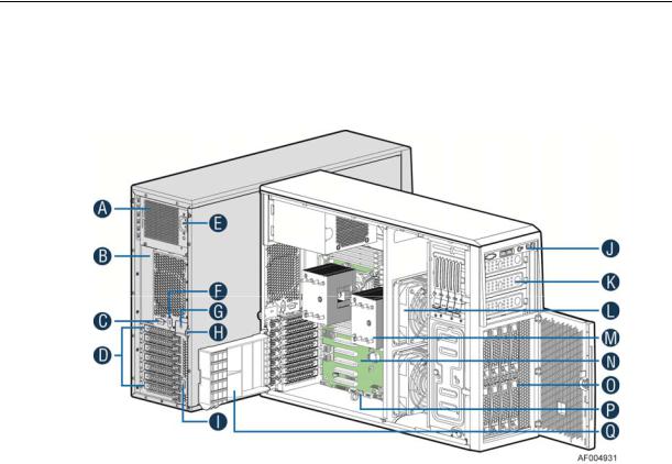
Intel® Server System P4308CP4MHEN View
A.550-W Fixed Power supply
B.I/O Ports
C.Alternate RMM4 Knockout
D.PCI Add-in Board Slot Covers
E.AC Input Power Connector
F.Serial Port Knockout
G.A Kensington* Cable Lock Mounting Hole
H.Padlock Loop
I.Alternate RMM4 Knockout
J.Front Control Panel
K.5.25” Peripheral Bays
L.Fixed System Fan
M.Heat-sink
N.Intel® Server Board S2600CP
O.8x3.5” Hot-swap HDD Cage
P.Intel® RAID C600 Upgrade Key
Q.PCI-e Retainer
Figure 1. Intel® Server System P4308CP4MHEN View
/NOTE:
Airduct is not shown
Intel® Server Board S2600CP Intel® Server System P4000CP Family Service Guide |
1 |
Server System Features
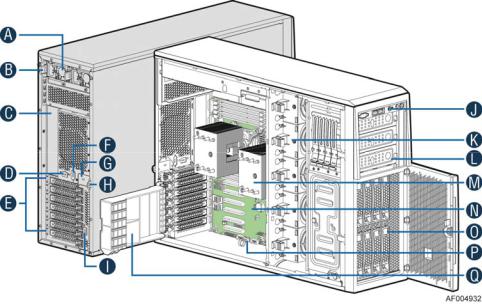
Intel® Server System P4308CP4MHGC View
A.750-W Redundant Power Supply
B.AC Input Power Connector
C.I/O Ports
D.Alternate RMM4 Knockout
E.PCI Add-in Board Slot Covers
F.Serial Port Knockout
G.A Kensington* Cable Lock Mounting Hole
H.Padlock Loop
I.Alternate RMM4 Knockout
J.Front Control Panel
K.Hot-swap System Fan
L.5.25” Peripheral Bays
M.Heat-sink
N.Intel® Server Board S2600CP
O.8x3.5” Hot-swap HDD Cage
P.Intel® RAID C600 Upgrade Key
Q.PCI-e Retainer
Figure 2. Intel® Server System P4308CP4MHGC View
/NOTE:
Airduct is not shown.
2 |
Intel® Server Board S2600CP Intel® Server System P4000CP Family Service Guide |
Server System Features
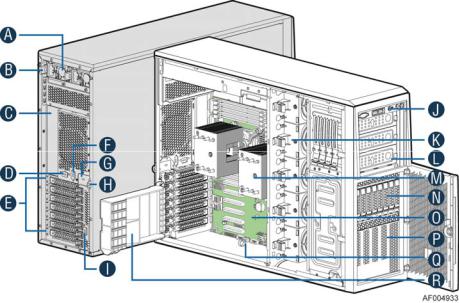
Intel® Server System P4208CP4MHGC View
A.750-W Redundant Power Supply
B.AC Input Power Connector
C.I/O Ports
D.Alternate RMM4 Knockout
E.PCI Add-in Board Slot Covers
F.Serial Port Knockout
G.A Kensington* Cable Lock Mounting Hole
H.Padlock Loop
I.Alternate RMM4 Knockout
J.Front Control Panel
K.Hot-swap System Fan
L.5.25” Peripheral Bays
M.Heat-sink
N.8x3.5” Hot-swap HDD Cage
O.Intel® Server Board S2600CP
P.EMI Cover
Q.Intel® RAID C600 Upgrade Key
R.PCI-e Retainer
Figure 3. Intel® Server System P4208CP4MHGC View
/NOTE:
Airduct is not shown.
Hot Swap Hard Drive Bay and Front Panel Options
The figure below shows the 8x3.5” drive bay for Intel® Server System P4308CP4MHEN and P4308CP4MHGC, and 8x2.5” drive bay for Intel® Server System P4208CP4MHGC.
Intel® Server Board S2600CP Intel® Server System P4000CP Family Service Guide |
3 |

Server System Features
Figure 4. Hot Swap Hard Drive Bay and Front Panel Options
Front Control Panel
Below figure show the layout of components on Front Control Panel.
Figure 5. Front Control Panel
4 |
Intel® Server Board S2600CP Intel® Server System P4000CP Family Service Guide |
Server System Features
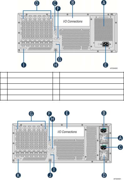
Back Panel
The following figures show the layout of Back Panel with 550-W fixed power supply and 750-W redundant power supplies.
A |
Power Supply |
F |
Serial-B Port (Optional) |
B |
IO Connectors |
G |
Kensington* Cable Lock Mounting Hole |
C |
RMM4 NIC Port (Optional) |
H |
Padlock Loop |
D |
Add in PCI-e cards |
I |
RMM4 NIC Port (Optional) |
E |
Power Connector |
|
|
Figure 6. Back Panel With 550-W PSU
A |
|
|
|
G |
|
|
|
|
|
Power Supply |
|
|
|
Add in PCI-e cards |
|
|
|
|
|
|
|
|
|
|
|
|
|
|
|
|
|
B |
|
Power Connector |
|
H |
|
Serial-B Port (Optional) |
|
|
|
|
|
|
|
|
|
C |
|
Power Connector |
|
I |
|
Kensington* Cable Lock Mounting Hole |
|
|
|
|
|
|
|
|
|
D |
|
Power Supply |
|
J |
|
Padlock Loop |
|
|
|
|
|
|
|
|
|
E |
|
IO Connectors |
|
K |
|
RMM4 NIC Port (Optional) |
|
|
|
|
|
|
|
|
|
F |
|
RMM4 NIC Port (Optional) |
|
|
|
|
|
|
|
|
|
|
|
|
|
Figure 7. Back Panel With 750-W PSU
Intel® Server Board S2600CP Intel® Server System P4000CP Family Service Guide |
5 |
Server System Features
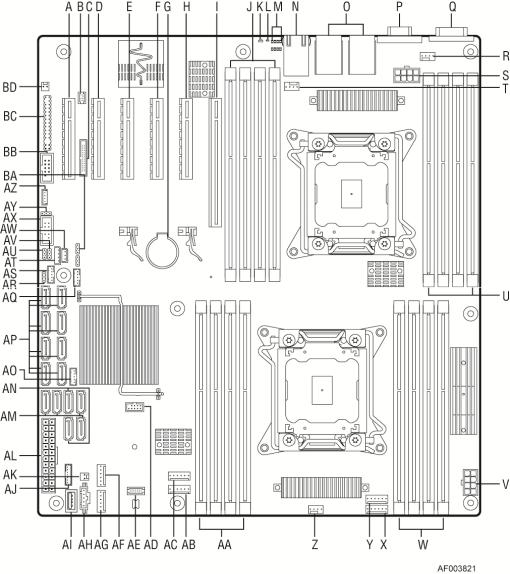
Server Board Components
This section helps you identify the components and connectors on the Intel® Server Board S2600CP.
Callout |
Description |
Callout |
Description |
|
A |
Slot 1, PCI Express* Gen3 |
AC |
System Fan 4 connector |
|
|
|
|
|
|
B |
RMM4 LITE |
AD |
Internal eUSB SSD |
|
|
|
|
|
|
C |
RMM4 NIC |
AE |
TPM |
|
|
|
|
|
|
D |
Slot 2, PCI Express* Gen3 |
AF |
System Fan 2 |
|
|
|
|
|
|
E |
Slot 3, PCI Express* Gen3, open-ended |
AG |
System Fan 1 |
|
|
|
|
|
|
F |
Slot 4, PCI Express* Gen3 |
AH |
PMBus |
|
|
|
|
|
|
G |
Battery |
AI |
Type-A USB |
|
|
|
|
|
|
H |
Slot 5, PCI Express* Gen3, from second processor, |
AJ |
LCP |
|
open-ended |
||||
|
|
|
||
|
|
|
|
|
6 |
Intel® Server Board S2600CP Intel® Server System P4000CP Family Service Guide |
|||
|
|
|
Server System Features |
|
|
|
|
|
|
Callout |
Description |
Callout |
Description |
|
I |
Slot 6, PCI Express* Gen3, support riser card |
AK |
HDD activity LED |
|
|
|
|
|
|
J |
DIMM E1/E2/F1/F2 |
AL |
Main Power |
|
|
|
|
|
|
K |
System Status LED |
AM |
SATA 3G connector |
|
|
|
|
|
|
L |
ID LED |
AN |
SATA 6G connector |
|
|
|
|
|
|
M |
Diagnostic LED |
AO |
SATA SGPIO |
|
|
|
|
|
|
N |
NIC 3/4 (only on Quad NIC board) |
AP |
SATA/SAS connector |
|
|
|
|
|
|
O |
USB 0/1/2/3, NIC 1,2 |
AQ |
SAS SGPIO 2 |
|
|
|
|
|
|
P |
VGA |
AR |
Password Clear |
|
|
|
|
|
|
Q |
Serial Port A |
AS |
SAS SGPIO 1 |
|
|
|
|
|
|
R |
Processor 2 Fan connector |
AT |
IPMB |
|
|
|
|
|
|
S |
Processor 2 Power connector |
AU |
ME Force Update |
|
|
|
|
|
|
T |
System Fan 7 connector |
AV |
BMC Force Update |
|
|
|
|
|
|
U |
DIMM H1/H2/G1/G2 |
AW |
HSBP_I2C |
|
|
|
|
|
|
V |
Processor 1 Power connector |
AX |
USB to front panel |
|
|
|
|
|
|
W |
DIMM A1/A2/B1/B2 |
AY |
BIOS Default |
|
|
|
|
|
|
X |
System Fan 5 connector |
AZ |
Intel C600 RAID Upgrade key connector |
|
|
|
|
|
|
Y |
System Fan 6 connector |
BA |
BIOS Recovery |
|
|
|
|
|
|
Z |
Processor 1 Fan connector |
BB |
Serial B connector |
|
|
|
|
|
|
AA |
DIMM C1/C2/D1/D2 |
BC |
SSI Front Panel (24-pin) and NIC 3/4 |
|
LED (4-pin) |
||||
|
|
|
||
|
|
|
|
|
AB |
System Fan 3 connector |
BD |
Chassis Intrusion |
|
|
|
|
|
Figure 8. Server Board Connector and Component Locations
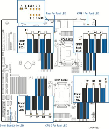
Intel® Light-Guided Diagnostics
The figure in below shows the locations of Diagnostic LEDs on Intel® Server Board S2600CP.
Intel® Server Board S2600CP Intel® Server System P4000CP Family Service Guide |
7 |
Server System Features
Figure 9. Intel® Light-Guided Diagnostic LEDs - Server Board
The server system contains the following diagnostic LEDs, each providing the following functions:
A - The System Status LED on the front and back panels shows the overall health of the system (green, blinking green, blinking amber, amber, off).
B - The System Identification LED on the front and back panel helps identify the server from among several servers. The ID LED is off by default, and blue when activated by button or software.
POST Code Diagnostic LEDs on the server board change color or state (off, green, red, amber) according to the POST sequence.
The 5V-STBY LED on the server board is illuminated (green) when power is applied.
CPU fault LEDs help identify the failure of CPU. The CPU fault LEDs turn on (amber) if there is a CPU fault.
DIMM Fault LEDs on the server board help identify failed and failing DIMM slots. The DIMM fault LEDs turn on (amber) if there is a DIMM fault.
8 |
Intel® Server Board S2600CP Intel® Server System P4000CP Family Service Guide |

Server System Features
System Jumpers
The figure below shows the locations of System Jumpers on Intel® Server Board S2600CP.
Jumper Name |
Pins |
System Results |
|
|
1-2 |
Pins 1-2 should be connected for normal system operation. (Default) |
|
BIOS Recovery |
|
|
|
2-3 |
The main system BIOS does not boot with pins 2-3 connected. The system only boots from EFI- |
||
|
bootable recovery media with a recovery BIOS image present. |
|
|
|
|
|
|
|
|
|
|
BIOS Default |
1-2 |
These pins should have a jumper in place for normal system operation. (Default) |
|
(a.k.a CMOS |
|
|
|
2-3 |
If pins 2-3 are connected when AC power unplugged, the CMOS settings clear in 5 seconds. |
|
|
Clear) |
Pins 2-3 should not be connected for normal system operation. |
|
|
|
|
||
|
|
|
|
ME Force |
1-2 |
ME Firmware Force Update Mode – Disabled (Default) |
|
Update |
2-3 |
ME Firmware Force Update Mode – Enabled |
|
|
|
|
|
BMC Force |
1-2 |
BMC Firmware Force Update Mode – Disabled (Default) |
|
Update |
2-3 |
BMC Firmware Force Update Mode – Enabled |
|
|
|
|
|
|
1-2 |
These pins should have a jumper in place for normal system operation. (Default) |
|
|
|
|
|
Password Clear |
|
To clear administrator and user passwords, power on the system with pins 2-3 connected. The |
|
2-3 |
administrator and user passwords clear in 5-10 seconds after power on. Pins 2-3 should not be |
|
|
|
|
||
|
|
connected for normal system operation. |
|
|
|
|
|
|
|
Figure 10. Configuration Jumpers |
|
Intel® Server Board S2600CP Intel® Server System P4000CP Family Service Guide |
9 |
||
Server System Features
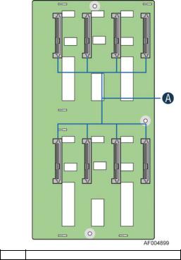
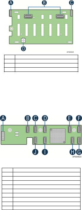
Hot-Swap SAS/SATA Backplane
The Hot-Swap SAS/SATA backplane serves as an interface between the mother board and the system drives. The following diagrams show the location for each connector found on the backplane.
8 x 3.5-inch Hard Drive Backplane
A SAS/SATA Hot-swap Connectors
Figure 11. 8x3.5 backplane – Front View
10 |
Intel® Server Board S2600CP Intel® Server System P4000CP Family Service Guide |
Server System Features
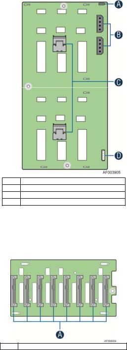
A |
Reserved |
B |
Power Connector |
C |
Mini-SAS Connectors |
D |
I2C In Connector |
Figure 12. 8x3.5 backplane – Rear View
8 x 2.5-inch Hard Drive Backplane
A SAS/SATA Hot-swap Connectors
Figure 13. 8 x 2.5 backplane - Front View
Intel® Server Board S2600CP Intel® Server System P4000CP Family Service Guide |
11 |
Server System Features
AI2C Out Connector
BMini-SAS Connectors
CI2C In Connector
DPower Connector
Figure 14. 8 x 2.5 backplane - Rear View
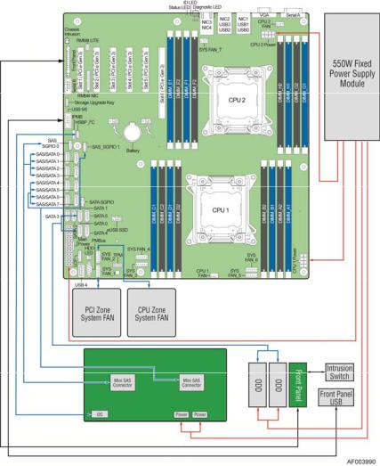
Intel® RAID Expander Cards (Upgrade Option)
Intel provides two types of internal RAID expander cards: 36 ports and 24 ports.
A |
Power Connector |
B |
Mini-SAS Connector A |
C |
Mini-SAS Connector B |
D |
Mini-SAS Connector G (36 port sku only) |
E |
Mini-SAS Connector H (36 port sku only) |
F |
Mini-SAS Connector I (36 port sku only) |
G |
Mini-SAS Connector F |
H |
Mini-SAS Connector E |
I |
Mini-SAS Connector D |
J |
Mini-SAS Connector C |
Figure 15. Internal Intel® RAID Expander Cards Components
12 |
Intel® Server Board S2600CP Intel® Server System P4000CP Family Service Guide |
Server System Features
Advanced Management Options
Intel® Remote Management Module 4
The Intel® Remote Management Module 4 plugs into a dedicated connector on the server board and provides additional server management functionality to the server board.
This module provides a dedicated web server for viewing server information and remote control of the system. It also provides Remote KVM Redirection and USB Media Redirection allowing USB devices attached to the remote system to be used on the managed server.
For instructions on installing the Intel® Remote Management Module 4, see “Installing and Removing the Intel® Remote Management Module 4”.
Intel® Server Board S2600CP Intel® Server System P4000CP Family Service Guide |
13 |

Hardware Installations and Upgrades
2 Hardware Installations and Upgrades
Before You Begin
Before working with your server product, pay close attention to the “Safety Information” at the beginning of this manual.
/NOTE
Whenever you service the system, you must first power down the server and unplug all peripheral devices and the power cord.
Tools and Supplies Needed
Phillips* (cross head) screwdriver (#1 bit and #2 bit)
Needle nosed pliers
Anti-static wrist strap and conductive foam pad (recommended)
System Reference
All references to left, right, front, top, and bottom assume the reader is facing the front of the chassis as it would be positioned for normal operation.
14 |
Intel® Server Board S2600CP Intel® Server System P4000CP Family Service Guide |
Hardware Installations and Upgrades
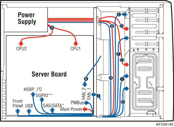
Cable Routing Recommendations
When you add or remove components from your server system, make sure your cables are routed correctly before reinstalling the server system cover. Use caution to make sure no cables or wires are pinched and that the airflow from the fans is not blocked. Use the figures below to determine the correct cable routing.
/NOTE:
To activate the port SATA/SAS 4-7 on the server board, a proper Intel® RAID C600 Upgrade Key must be installed. For instructions, see Intel® RAID C600 Upgrade Key Installation Guide.
Cable connections for Intel® Server System P4308CP4MHEN:
Figure 16. Cable connections for Intel® Server System P4308CP4MHEN
Intel® Server Board S2600CP Intel® Server System P4000CP Family Service Guide (Preliminary) |
15 |
Hardware Installations and Upgrades
Cable routing for Intel® Server System P4308CP4MHEN:
Callout |
Description |
Callout |
Description |
|
A |
CPU1/CPU2 Power Cable |
B |
Server Board Main Power Cable |
|
C |
Hot-swap Backplane Power Cable |
D |
ODD Power Cable |
|
E |
Front Panel Cable, USB Cable |
F |
ODD Data Cable (Connect To White SATA 6G |
|
Connectors On Server Board) |
||||
|
|
|
||
G |
MiniSAS and SGPIO Cable |
H |
PMBus |
|
I |
Hot-swap Backplane I2C Cable |
J |
System Fan 1 Cable |
|
K |
System Fan 2 Cable |
|
|
Figure 17. Cable routing for Intel® Server System P4308CP4MHEN
16 |
Intel® Server Board S2600CP Intel® Server System P4000CP Family Service Guide |
 Loading...