


Intel® Server Boards S5000PSL
and S5000XSL
Technical Product Specification
Intel order number: D41763-003
Revision 1.2
September 2006
Enterprise Platforms and Services Division – Marketing
ii |
Revision 1.2 |
|
Intel order number: D41763-003 |

Intel® Server Boards S5000PSL and S5000XSL |
Revision History |
|
|
|
|
|
Revision History |
|
|
|
|
|
Date |
Revision |
Modifications |
|
|
Number |
|
|
November 2005 |
0.5 |
Preliminary Draft |
|
|
|
|
|
March 2006 |
0.9 |
Updated all sections with the latest product information, updated illustrations, |
|
|
|
added section for Regulatory/Certification, added appendix for Sensor Table, |
|
|
|
POST Code Diagnostic LED’s, POST Code & Error Handling, Supported Chassis, |
|
|
|
Added references for the S5000XSL. |
|
|
|
|
|
May 2006 |
1.0 |
Updated the Server Board picture and Block Diagram, added information for |
|
|
|
which slot the ROMB card goes into, added information on the HDD LED Header, |
|
|
|
added information on the Snoop Filter, and cleaned other general things up in the |
|
|
|
document. |
|
|
|
|
|
September 2006 |
1.1 |
Updated legal disclaimer; Updated Processor Table; Updated Memory Section |
|
|
|
|
|
September 2006 |
1.2 |
Updated Reference Documents |
|
|
|
|
Disclaimers
Information in this document is provided in connection with Intel® products. No license, express or implied, by estoppel or otherwise, to any intellectual property rights is granted by this document. Except as provided in Intel's Terms and Conditions of Sale for such products, Intel assumes no liability whatsoever, and Intel disclaims any express or implied warranty, relating to sale and / or use of Intel products including liability or warranties relating to fitness for a particular purpose, merchantability, or infringement of any patent, copyright or other intellectual property right. Intel products are not intended for use in medical, life saving, or life sustaining applications. Intel may make changes to specifications and product descriptions at any time, without notice.
Designers must not rely on the absence or characteristics of any features or instructions marked "reserved" or "undefined." Intel reserves these for future definition and shall have no responsibility whatsoever for conflicts or incompatibilities arising from future changes to them.
The Intel® Server Boards S5000PSL and S5000XSL may contain design defects or errors known as errata which may cause the product to deviate from published specifications. Refer to the Intel® Server Boards S5000PSL and S5000XSL Specification Update for published errata.
Intel Corporation server baseboards contain a number of high-density VLSI and power delivery components that need adequate airflow to cool. Intel’s own chassis are designed and tested to meet the intended thermal requirements of these components when the fully integrated system is used together. It is the responsibility of the system integrator that chooses not to use Intel developed server building blocks to consult vendor datasheets and operating parameters to determine the amount of air flow required for their specific application and environmental conditions. Intel Corporation can not be held responsible if components fail or the server board does not operate correctly when used outside any of their published operating or non-operating limits.
Intel, Pentium, Itanium, and Xeon are trademarks or registered trademarks of Intel Corporation.
*Other brands and names may be claimed as the property of others.
Copyright © Intel Corporation 2006.
Revision 1.2 |
iii |
Intel order number: D41763-003

Table of Contents Intel® Server Boards S5000PSL and S5000XSL TPS
Table of Contents
1. |
Introduction ........................................................................................................................ |
12 |
||
|
|
1.1 |
Chapter Outline...................................................................................................... |
12 |
|
|
1.2 |
Server Board Use Disclaimer ................................................................................ |
12 |
2. |
Server Board Overview...................................................................................................... |
14 |
||
|
|
2.1 |
Server Board Feature Set...................................................................................... |
14 |
|
|
2.2 |
Server Board Layout.............................................................................................. |
17 |
|
|
2.2.1 |
Server Board Connector and Component Layout.................................................. |
18 |
|
|
2.2.2 |
Server Board Mechanical Drawings ...................................................................... |
20 |
|
|
2.2.3 |
Server Board ATX I/O Layout ................................................................................ |
26 |
3. |
Functional Architecture ..................................................................................................... |
27 |
||
|
|
3.1 |
Intel® 5000P / 5000X Memory Controller Hub (MCH)............................................ |
29 |
|
|
3.1.1 |
System Bus Interface............................................................................................. |
29 |
|
|
3.1.2 |
Processor Support ................................................................................................. |
29 |
|
|
3.1.3 |
Memory Sub-system.............................................................................................. |
32 |
|
|
3.1.4 |
Snoop Filter (5000X MCH only)............................................................................. |
41 |
|
|
3.2 |
Enterprise South Bridge (ESB2-E) ........................................................................ |
41 |
|
|
3.2.1 |
PCI Sub-system..................................................................................................... |
42 |
|
|
3.2.2 |
Serial ATA Support ................................................................................................ |
44 |
|
|
3.2.3 |
Parallel ATA (PATA) Support ................................................................................ |
45 |
|
|
3.2.4 |
USB 2.0 Support.................................................................................................... |
45 |
|
|
3.3 |
Video Support ........................................................................................................ |
45 |
|
|
3.3.1 |
Video Modes.......................................................................................................... |
47 |
|
|
3.3.2 |
Video Memory Interface......................................................................................... |
47 |
|
|
3.3.3 |
Dual Video ............................................................................................................. |
47 |
|
|
3.4 |
SAS Controller ....................................................................................................... |
48 |
|
|
3.4.1 |
SAS RAID Support ................................................................................................ |
48 |
|
|
3.4.2 |
SAS / SATA Connector Sharing ............................................................................ |
48 |
|
|
3.5 |
Network Interface Controller (NIC) ........................................................................ |
48 |
|
|
3.5.1 |
Intel® I/O Acceleration Technolgy .......................................................................... |
49 |
|
|
3.5.2 |
MAC Address Definition......................................................................................... |
49 |
|
|
3.6 |
Super I/O ............................................................................................................... |
49 |
|
|
3.6.1 |
Serial Ports ............................................................................................................ |
50 |
|
|
|
|
|
|
iv |
|
Intel order number: D41763-003 |
Revision 1.2 |
|
|
|
|
|
Intel® Server Boards S5000PSL and S5000XSL TPS |
Table of Contents |
||||
|
3.6.2 |
Floppy Disk Controller ........................................................................................... |
50 |
||
|
3.6.3 |
Keyboard and Mouse Support ............................................................................... |
50 |
||
|
3.6.4 |
Wake-up Control.................................................................................................... |
50 |
||
|
3.6.5 |
System Health Support.......................................................................................... |
50 |
||
4. |
Platform Management........................................................................................................ |
51 |
|||
5. Connector / Header Locations and Pin-outs.................................................................... |
53 |
||||
|
5.1 |
Board Connector Information................................................................................. |
53 |
||
|
5.2 |
Power Connectors ................................................................................................. |
54 |
||
|
5.3 |
System Management Headers .............................................................................. |
56 |
||
|
5.3.1 |
Intel® Remote Management Module (Intel® RMM) Connector............................... |
56 |
||
|
5.3.2 |
LCP / AUX IPMB Header....................................................................................... |
57 |
||
|
5.3.3 |
IPMB Header ......................................................................................................... |
58 |
||
|
5.3.4 |
HSBP Header ........................................................................................................ |
58 |
||
|
5.3.5 |
SGPIO Header....................................................................................................... |
58 |
||
|
5.3.6 |
SES I2C.................................................................................................................. |
58 |
||
|
5.3.7 |
HDD Activity LED Header...................................................................................... |
59 |
||
|
5.4 |
Front Panel Connector........................................................................................... |
59 |
||
|
5.5 |
I/O Connectors....................................................................................................... |
59 |
||
|
5.5.1 |
VGA Connector...................................................................................................... |
59 |
||
|
5.5.2 |
NIC Connectors ..................................................................................................... |
60 |
||
|
5.5.3 |
IDE Connector ....................................................................................................... |
60 |
||
|
5.5.4 |
Intel® Remote Management Module NIC Connector ............................................. |
61 |
|
|
|
5.5.5 |
SATA / SAS Connectors........................................................................................ |
63 |
||
|
5.5.6 |
Serial Port Connectors........................................................................................... |
63 |
||
|
5.5.7 |
Keyboard and Mouse Connector ........................................................................... |
64 |
||
|
5.5.8 |
USB Connector...................................................................................................... |
65 |
||
|
5.6 |
Fan Headers .......................................................................................................... |
66 |
||
6. |
Jumper Blocks.................................................................................................................... |
68 |
|
||
|
6.1 |
CMOS Clear and Password Reset Usage Procedure ........................................... |
69 |
|
|
|
6.2 |
BMC Force Update Procedure .............................................................................. |
69 |
||
|
6.3 |
BIOS Select Jumper .............................................................................................. |
70 |
||
7. Intel® Light Guided Diagnostics........................................................................................ |
71 |
||||
|
7.1 |
5 Volt Standby LED ............................................................................................... |
71 |
||
|
7.2 |
Fan Fault LEDs...................................................................................................... |
72 |
||
|
7.3 |
System ID LED and System Status LED ............................................................... |
73 |
||
|
|
|
|
|
|
Revision 1.2 |
Intel order number: D41763-003 |
v |
|||
|
|
|
|
|
|

Table of Contents |
Intel® Server Boards S5000PSL and S5000XSL TPS |
||
7.3.1 |
System Status LED – BMC Initialization................................................................ |
74 |
|
7.4 |
DIMM Fault LEDs .................................................................................................. |
|
76 |
7.5 |
Processor Fault LEDs............................................................................................ |
|
77 |
7.6 |
Post Code Diagnostic LEDs .................................................................................. |
|
78 |
8. Design and Environmental Specifications....................................................................... |
79 |
||
8.1 |
Server Boards S5000PSL and S5000XSL Design Specifications ......................... |
79 |
|
8.2 |
Server Board Power Requirements ....................................................................... |
80 |
|
8.2.1 |
Processor Power Support...................................................................................... |
|
81 |
8.3 |
Power Supply Output Requirements ..................................................................... |
81 |
|
8.3.1 |
Grounding .............................................................................................................. |
|
82 |
8.3.2 |
Standby Outputs .................................................................................................... |
|
82 |
8.3.3 |
Remote Sense ....................................................................................................... |
|
82 |
8.3.4 |
Voltage Regulation ................................................................................................ |
|
83 |
8.3.5 |
Dynamic Loading ................................................................................................... |
|
83 |
8.3.6 |
Capacitive Loading ................................................................................................ |
|
84 |
8.3.7 |
Ripple / Noise ........................................................................................................ |
|
84 |
8.3.8 |
Timing Requirements............................................................................................. |
|
84 |
8.3.9 |
Residual Voltage Immunity in Standby Mode ........................................................ |
87 |
|
9. Regulatory and Certification Information......................................................................... |
88 |
||
9.1 |
Product Regulatory Compliance ............................................................................ |
|
88 |
9.1.1 |
Product Safety Compliance ................................................................................... |
|
88 |
9.1.2 |
Product EMC Compliance – Class A Compliance ................................................. |
88 |
|
9.1.3 |
Certifications / Registrations / Declarations........................................................... |
89 |
|
9.2 |
Product Regulatory Compliance Markings ............................................................ |
89 |
|
9.3 |
Electromagnetic Compatibility Notices .................................................................. |
90 |
|
9.3.1 |
FCC Verification Statement (USA) ........................................................................ |
90 |
|
9.3.2 |
ICES-003 (Canada) ............................................................................................... |
|
90 |
9.3.3 |
Europe (CE Declaration of Conformity) ................................................................. |
91 |
|
9.3.4 |
VCCI (Japan) ......................................................................................................... |
|
91 |
9.3.5 |
BSMI (Taiwan) ....................................................................................................... |
|
91 |
9.3.6 |
RRL (Korea)........................................................................................................... |
|
91 |
9.3.7 |
CNCA (CCC-China)............................................................................................... |
|
92 |
9.4 |
Restriction of Hazardous Substances (RoHS) Compliance................................... |
92 |
|
Appendix A: Integration and Usage Tips................................................................................ |
|
93 |
|
Appendix B: BMC Sensor Tables ............................................................................................ |
|
94 |
|
vi |
|
|
Revision 1.2 |
|
Intel order number: D41763-003 |
|
|

Intel® Server Boards S5000PSL and S5000XSL TPS |
Table of Contents |
Appendix C: POST Code Diagnostic LED Decoder |
............................................................. 109 |
Appendix D: POST Code Errors ............................................................................................ |
114 |
Appendix E: Supported Intel® Server Chassis ..................................................................... |
117 |
Glossary................................................................................................................................... |
118 |
Reference Documents ............................................................................................................ |
121 |
Revision 1.2 |
vii |
|
Intel order number: D41763-003 |

List of Figures |
Intel® Server Boards S5000PSL and S5000XSL TPS |
|
List of Figures |
|
|
Figure 1. Server Board Photograph ............................................................................................ |
|
17 |
Figure 2. Major Board Components............................................................................................ |
|
19 |
Figure 3. Mounting Hole Positions.............................................................................................. |
|
20 |
Figure 4. Component Positions................................................................................................... |
|
21 |
Figure 5. Restricted Areas on Side 1.......................................................................................... |
|
22 |
Figure 6. Restricted Areas on Side 2.......................................................................................... |
|
23 |
Figure 7. Restricted Areas on Side 2, “Detail B”......................................................................... |
24 |
|
Figure 8. CPU and Memory Duct Keepout ................................................................................. |
|
25 |
Figure 9. ATX I/O Layout ............................................................................................................ |
|
26 |
Figure 10. Functional Block Diagram.......................................................................................... |
|
28 |
Figure 11. CEK Processor Mounting .......................................................................................... |
|
31 |
Figure 12. Memory Layout .......................................................................................................... |
|
32 |
Figure 13. Minimum Two DIMM Memory Configuration.............................................................. |
37 |
|
Figure 14. Recommended Four DIMM Configuration ................................................................. |
38 |
|
Figure 15. Single Branch Mode Sparing DIMM Configuration .................................................... |
40 |
|
Figure 16. SMBUS Block Diagram.............................................................................................. |
|
52 |
Figure 17. Jumper Blocks (J1C3, J1D1, J1D2, J1E32) .............................................................. |
68 |
|
Figure 18. 5 Volt Standby Status LED Location.......................................................................... |
71 |
|
Figure 19. Fan Fault LED Locations ........................................................................................... |
|
72 |
Figure 20. System ID LED and System Status LED Locations................................................... |
73 |
|
Figure 21. DIMM Fault LED Locations........................................................................................ |
|
76 |
Figure 22. Processor Fault LED Locations ................................................................................. |
|
77 |
Figure 23. POST Code Diagnostic LED Location ....................................................................... |
78 |
|
Figure 24. Power Distribution Block Diagram ............................................................................. |
|
80 |
Figure 25. Output Voltage Timing ............................................................................................... |
|
85 |
Figure 26. Turn On/Off Timing (Power Supply Signals).............................................................. |
86 |
|
Figure 27. Diagnostic LED Placement Diagram ....................................................................... |
109 |
|
viii |
Revision 1.2 |
|
Intel order number: D41763-003 |

Intel® Server Boards S5000PSL and S5000XSL TPS |
List of Tables |
List of Tables |
|
Table 1. Server Board Features.................................................................................................. |
14 |
Table 2. Processor Support Matrix ............................................................................................. |
29 |
Table 3. I2C Addresses for Memory Module SMB ...................................................................... |
33 |
Table 4. Maximum Eight-DIMM System Memory Configruation – x8 Single Rank ..................... |
34 |
Table 5. Maximum Eight-DIMM System Memory Configuration – x4 Dual Rank........................ |
34 |
Table 6. PCI Bus Segment Characteristics................................................................................. |
42 |
Table 7. Video Modes................................................................................................................. |
47 |
Table 8. NIC2 Status LED........................................................................................................... |
48 |
Table 9. Serial B Header Pin-out ................................................................................................ |
50 |
Table 10. Board Connector Matrix .............................................................................................. |
53 |
Table 11. Power Connector Pin-out (J9B5) ................................................................................ |
54 |
Table 12. 12 V Power Connector Pin-out (J3J2) ........................................................................ |
55 |
Table 13. Power Supply Signal Connector Pin-out (J9D1) ......................................................... |
55 |
Table 14. P12V4 Power Connector Pin-out (J5A2) .................................................................... |
55 |
Table 15. RMM Connector Pin-out (J5B1).................................................................................. |
56 |
Table 16. LPC / AUX IPMB Header Pin-out (J2J1)..................................................................... |
57 |
Table 17. IPMB Header Pin-out (J4J1) ....................................................................................... |
58 |
Table 18. HSBP Header Pin-out (J1J7, J1J2) ............................................................................ |
58 |
Table 19. SGPIO Header Pin-out (J2H1, J1J5) .......................................................................... |
58 |
Table 20. SES I2C Header Pin-out (J1J3)................................................................................... |
58 |
Table 21. HDD Activity LED Header Pin-out (J2J3).................................................................... |
59 |
Table 22. Front Panel SSI Standard 24-pin Connector Pin-out (J1E4) ...................................... |
59 |
Table 23. VGA Connector Pin-out (J7A1)................................................................................... |
59 |
Table 24. RJ-45 10/100/1000 NIC Connector Pin-out (JA6A1, JA6A2)...................................... |
60 |
Table 25. IDE 40-pin Connector Pin-out (J2J2).......................................................................... |
60 |
Table 26. 40-pin RMM NIC Module Connector Pin-out (J3B2)................................................... |
61 |
Table 27. SATA / SAS Connector Pin-out (J1J1, J1H2, J1H1, J1G2, J1G1, J1F2) ................... |
63 |
Table 28. External DB9 Serial A Port Pin-out (J7A1).................................................................. |
63 |
Table 29. Internal 9-pin Serial B Header Pin-out (J1B1)............................................................. |
64 |
Table 30. Stacked PS/2 Keyboard and Mouse Port Pin-out (J9A1) ........................................... |
64 |
Table 31. External USB Connector Pin-out (JA6A1, JA6A2)...................................................... |
65 |
Table 32. Internal USB Connector Pin-out (J3J1)....................................................................... |
65 |
Revision 1.2 |
ix |
Intel order number: D41763-003 |
|

List of Tables |
Intel® Server Boards S5000PSL and S5000XSL TPS |
|
Table 33. SSI 4-pin Fan Header Pin-out (J9J1, J5J1, J9B3, J9B4)............................................ |
66 |
|
Table 34. SSI 6-pin Fan Header Pin-out (J3H1, J3H2, J3H3, J3H4).......................................... |
66 |
|
Table 35. Server Board Jumpers (J1C3, J1D1, J1D2, J1E3) ..................................................... |
68 |
|
Table 36. System Status LED..................................................................................................... |
|
74 |
Table 37. Server Board Design Specifications |
........................................................................... |
79 |
Table 38. Intel® Xeon® Processor Dual Processor TDP Guidelines ........................................... |
81 |
|
Table 39. 550 W Load Ratings ................................................................................................... |
|
81 |
Table 40. Voltage Regulation Limits ........................................................................................... |
|
83 |
Table 41. Transient Load Requirements..................................................................................... |
|
83 |
Table 42. Capacitive Loading Conditions ................................................................................... |
|
84 |
Table 43. Ripple and Noise......................................................................................................... |
|
84 |
Table 44. Output Voltage Timing ................................................................................................ |
|
85 |
Table 45. Turn On/Off Timing ..................................................................................................... |
|
86 |
Table 46. BMC Sensors.............................................................................................................. |
|
96 |
Table 47. POST Progress Code LED Example ........................................................................ |
110 |
|
Table 48. Diagnostic LED POST Code Decoder ...................................................................... |
110 |
|
Table 49. POST Error Messages and Handling........................................................................ |
114 |
|
Table 50. POST Error Beep Codes .......................................................................................... |
|
116 |
Table 51. BMC Beep Codes ..................................................................................................... |
|
116 |
x |
Revision 1.2 |
|
Intel order number: D41763-003 |

Intel® Server Boards S5000PSL and S5000XSL TPS |
List of Tables |
This page intentionally left blank
Revision 1.2 |
xi |
|
Intel order number: D41763-003 |
Server Board Overview |
Intel® Server Boards S5000PSL and S5000XSL TPS |
1.Introduction
This Technical Product Specification (TPS) provides board-specific information about the features, functionality, and high-level architecture of the Intel® Server Boards S5000PSL and S5000XSL. See the Intel® S5000 Server Board Family Datasheet for details about board sub-systems, including the chipset, BIOS, and server management.
In addition, design level information for specific sub-systems can be obtained by ordering the External Product Specifications (EPS) for a given sub-system. EPS documents are not publicly available and must be ordered through your local Intel representative.
1.1Chapter Outline
This document is divided into the following chapters
Chapter 1 – Introduction
Chapter 2 – Server Board Overview
Chapter 3 – Functional Architecture
Chapter 4 – Platform Management
Chapter 5 – Connector and Header Location and Pin-out
Chapter 6 – Configuration Jumpers
Chapter 7 – Light-Guided Diagnostics
Chapter 8 – Power and Environmental specifications
Chapter 9 – Regulatory and Certification Information
Appendix A – Integration and Usage Tips
Appendix B – BMC Sensor Tables
Appendix C – POST Code Diagnostic LED Decoder
Appendix D – POST Code Errors
Appendix E – Supported Intel® Server Chassis
1.2Server Board Use Disclaimer
Intel Corporation server boards support add-in peripherals and contain a number of high-density VLSI and power delivery components that need adequate airflow to cool. Intel ensures through its own chassis development and testing that when Intel server
12 |
Revision 1.2 |
|
Intel order number: D41763-003 |

Intel® Server Boards S5000PSL and S5000XSL TPS |
List of Tables |
building blocks are used together, the fully integrated system will meet the intended thermal requirements of these components. It is the responsibility of the system integrator who chooses not to use Intel-developed server building blocks to consult vendor datasheets and operating parameters to determine the amount of air flow required for their specific application and environmental conditions. Intel Corporation cannot be held responsible if components fail or the server board does not operate correctly when used outside any of their published operating or non-operating limits.
Revision 1.2 |
13 |
|
Intel order number: D41763-003 |

Server Board Overview |
Intel® Server Boards S5000PSL and S5000XSL TPS |
2.Server Board Overview
The Intel® Server Boards S5000PSL and S5000XSL are monolithic printed circuit boards with features that support the pedestal server markets.
2.1Server Board Feature Set
|
Table 1. Server Board Features |
|
|
Feature |
Description |
Processors |
Socket J (771-pin LGA sockets) supporting one or two Dual-Core Intel® Xeon® |
|
processors 5000 sequence, with system bus speeds of 667 MHz, 1066 MHz, and |
|
1333 MHz. |
|
|
Memory |
Eight DIMM sockets supporting fully buffered DIMM technology (FBDIMM) memory. |
|
240-pin DDR2-533 and DDR2-677 FBDIMMs can be used. |
|
|
Chipset |
Intel® 5000P Memory Controller Hub (Server Board S5000PSL only) |
|
Intel® 5000X Memory Controller Hub (Server Board S5000XSL only) |
|
Intel® ESB2-E I/O Controller |
14 |
Revision 1.2 |
|
Intel order number: D41763-003 |

|
Intel® Server Boards S5000PSL and S5000XSL TPS |
List of Tables |
||
|
|
|
|
|
|
Feature |
Description |
|
|
|
On-board |
External connections: |
|
|
|
Connectors/Headers |
Stacked PS/2* ports for keyboard and mouse |
|
|
|
|
|
|
|
|
|
Stacked video / DB9 serial port A connector |
|
|
|
|
Two RJ45 / 2xUSB connectors for 10 / 100 / 1000 Mb and USB 2.0 support |
|
|
|
|
One USB 2x5 pin header, which supports two USB ports |
|
|
|
|
One USB port Type A connector |
|
|
|
|
One DH10 serial port B header |
|
|
|
|
Six SATA-2 connectors with integrated RAID 0, 1, and 10 support |
|
|
|
|
(order code S5000PSLSATA only) |
|
|
|
|
Software RAID 5 support through an optional SATA RAID KEY (this feature is |
|
|
|
|
currently not supported and will be made available after production launch) |
|
|
|
|
Two SATA-2 connectors and four SATA-2 / SAS connectors with integrated RAID |
|
|
|
|
0, 1, and 10 support (order code S5000PSLSAS only) |
|
|
|
|
Software RAID 5 support through an optional SAS RAID KEY (order code |
|
|
|
|
S5000PSLSAS only; this feature is currently not supported and will be made |
|
|
|
|
available after production launch) |
|
|
|
|
One ATA100 40-pin connector |
|
|
|
|
One RMM connector to support the optional Intel® Remote Management Module |
|
|
|
|
One I/O connector supporting an optional RMM NIC I/O module |
|
|
|
|
SSI-compliant front panel header |
|
|
|
|
SSI-compliant 24-pin main power connector, supporting the ATX-12 V standard |
|
|
|
|
on the first 20 pins |
|
|
|
|
|
|
|
|
Add-in PCI, PCI-X*, PCI |
One full-length / full-height PCI-X 64-bit slot with up to 133-MHz support when |
|
|
|
Express* Cards |
only one PCI-X slot is populated |
|
|
|
|
One full-length / full-height PCI-X 64-bit slot with up to 100 MHz support |
|
|
|
|
One full-length / full-height PCI Express* x8 (x4 throughput); x8 (x8 throughput) |
|
|
|
|
with order code S5000PSLSATA) slot |
|
|
|
|
One half-length / full-height PCI Express* x8 (x8 throughput) slot |
|
|
|
|
Two full-length / full-height PCI Express* x16 (x8 throughput) slots |
|
|
|
|
|
|
|
|
Video |
On-board ATI* ES1000 video controller with 16-MB DDR SDRAM |
|
|
|
|
|
|
|
|
Hard Drive |
Support for six SATA-2 hard drives |
|
|
|
|
Support for four SAS hard drives (order code S5000PSLSAS only) |
|
|
|
|
|
|
|
|
LAN |
Two 10 / 100 / 1000 Intel® 82563EB PHYs supporting Intel® I/O Acceleration |
|
|
|
|
Technology |
|
|
|
|
|
|
|
Revision 1.2 |
15 |
|
Intel order number: D41763-003 |

|
Server Board Overview |
Intel® Server Boards S5000PSL and S5000XSL TPS |
||
|
|
|
|
|
|
Feature |
|
Description |
|
|
Fans |
|
Support for |
|
|
|
|
Two processor fans |
|
|
|
|
Four front hot-swap fans |
|
|
|
|
Two rear system fans |
|
|
|
|
|
|
|
Server Management |
|
Support for Intel® System Management Software |
|
16 |
Revision 1.2 |
|
Intel order number: D41763-003 |
Intel® Server Boards S5000PSL and S5000XSL TPS |
List of Tables |
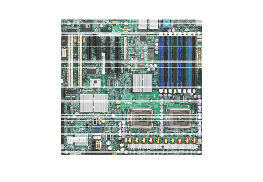
2.2Server Board Layout
Figure 1. Server Board Photograph
Revision 1.2 |
17 |
|
Intel order number: D41763-003 |
Server Board Overview |
Intel® Server Boards S5000PSL and S5000XSL TPS |
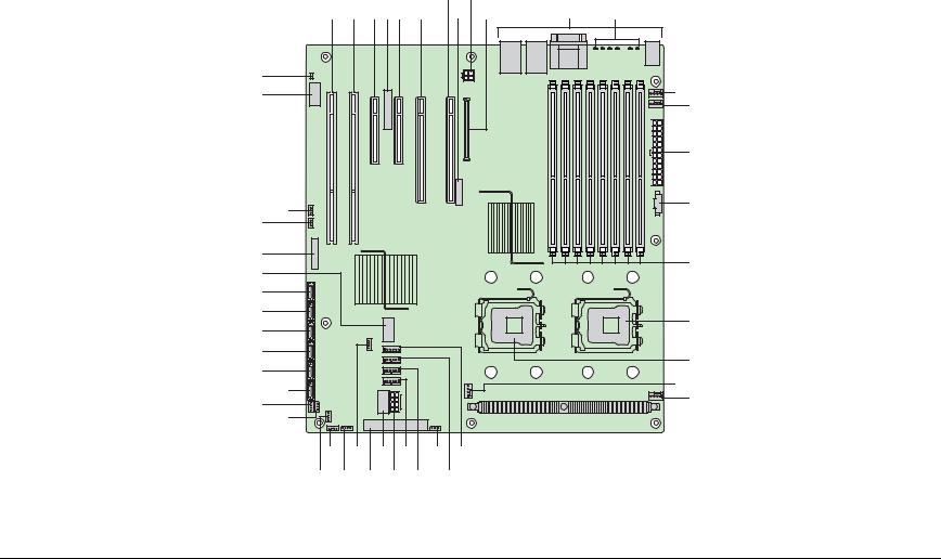
2.2.1Server Board Connector and Component Layout
The following figure shows the board layout of the server board. Each connector and major component is identified by a letter. A table of component descriptions follows the figure.
G |
I |
K |
L |
A B C DE F H |
J |
||
UU |
|
|
M |
TT |
|
|
|
|
|
|
N |
|
|
|
O |
RR SS |
|
|
P |
|
|
|
|
Q |
|
PP |
|
|
|
|
|
OO |
|
|
NN |
|
R |
MM |
|
|
|
|
|
LL |
|
S |
KK |
|
|
|
T |
|
JJ |
|
|
|
U |
|
II |
|
|
HH |
|
|
FF DD BB Z |
X |
V |
GG EE CC AA Y |
W |
AF000247 |
18 |
Revision 1.2 |
Intel order number: D41763-003

|
Intel® Server Boards S5000PSL and S5000XSL TPS |
List of Tables |
||
|
|
|
|
|
|
A. PCI-X 64-bit, 100-MHz slot 1 |
Q. DIMM sockets |
GG. Enclosure management SAS |
|
|
|
|
SGPIO header (order code |
|
|
|
|
S5000PSLSAS only) |
|
|
|
|
|
|
|
B. PCI-X 64-bit, 133-/100-MHz slot 2 |
R. Processor 1 socket |
HH. Enclosure management SAS |
|
|
|
|
SES I2C (order code S5000PSLSAS |
|
|
|
|
only) |
|
|
C. PCI Express* x4 / x8 slot 3 |
S. Processor 2 socket |
II. Hot-swap backplane A header |
|
|
|
|
|
|
|
D. Advanced Server Management |
T. Processor 2 fan header |
JJ. SATA 0 |
|
|
Interface NIC connector |
|
|
|
|
|
|
|
|
|
E. PCI Express* x4 slot 4 (ROMB |
U. Processor 1 fan header |
KK. SATA 1 |
|
|
Slot) |
|
|
|
|
F. PCI Express x8 slot 5 |
V. System fan 4 header |
LL. SATA 2 or SAS 0 (SAS 0 on |
|
|
|
|
order code S5000PSLSAS only) |
|
|
|
|
|
|
|
G. PCI Express x8 slot 6 |
W. System fan 3 header |
MM. SATA 3 or SAS 1 (SAS 1 on |
|
|
|
|
order code S5000PSLSAS only) |
|
|
|
|
|
|
|
H. CMOS battery |
X. IPMB connector |
NN. SATA 4 or SAS 2 (SAS 2 on |
|
|
|
|
order code S5000PSLSAS only) |
|
|
I. P12V4 connector |
Y. System fan 2 header |
OO. SATA 5 or SAS 3 (SAS 3 on |
|
|
|
|
order code S5000PSLSAS only) |
|
|
|
|
|
|
|
J. RMM connector (connector for |
Z. System fan 1 header |
PP. USB port |
|
|
Intel® Remote Management Module) |
|
|
|
|
K. Back panel I/O ports |
AA. Processor power connector |
QQ. Front control panel header |
|
|
|
|
|
|
|
L. Diagnostic and identify LEDs |
BB. USB header |
RR. SATA software RAID 5 key |
|
|
|
|
connector |
|
|
|
|
|
|
|
M. System fan 6 header |
CC. IDE connector |
SS. SAS software RAID 5 key |
|
|
|
|
connector (order code |
|
|
|
|
S5000PSLSAS only) |
|
|
|
|
|
|
|
N. System fan 5 header |
DD. Enclosure management SATA |
TT. Serial B / emergency |
|
|
|
SGPIO header |
management port header |
|
|
O. Main power connector |
EE. Intel® Local Control Panel |
UU. Chassis intrusion header |
|
|
|
header |
|
|
|
|
|
|
|
|
P. Auxilliary power signal connector |
FF. Hot-swap backplane B header |
|
|
|
|
|
|
|
Figure 2. Major Board Components
Revision 1.2 |
19 |
|
Intel order number: D41763-003 |
Server Board Overview |
Intel® Server Boards S5000PSL and S5000XSL TPS |
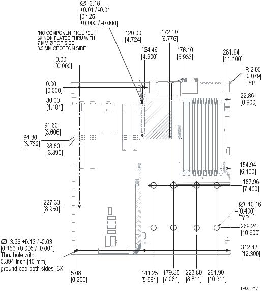
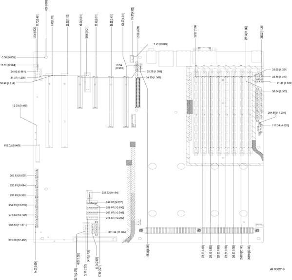
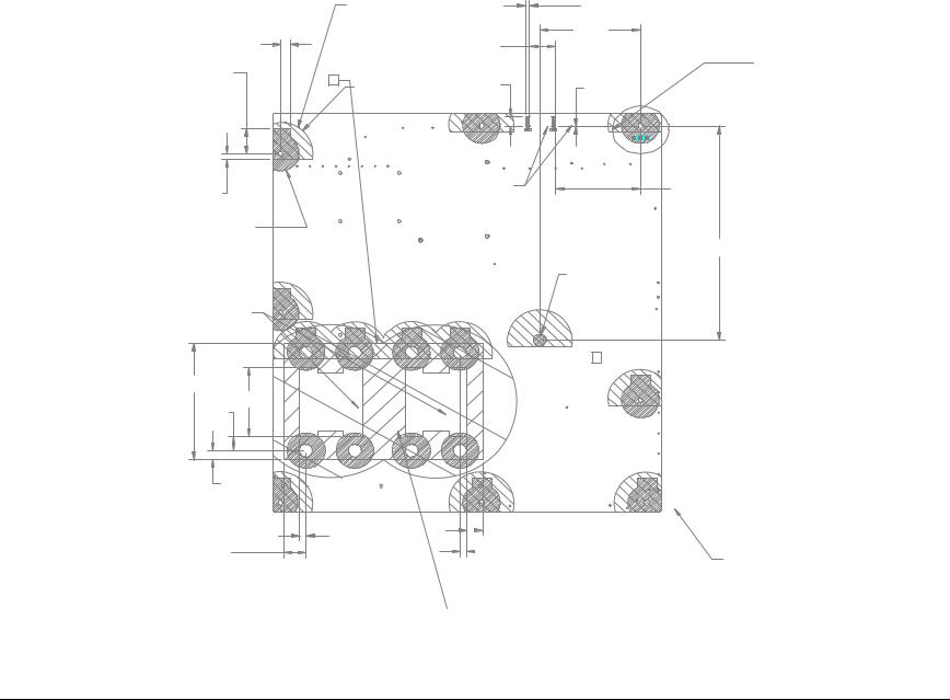
2.2.2Server Board Mechanical Drawings
|
|
Figure 3. Mounting Hole Positions |
|
|
|
20 |
Revision 1.2 |
|
|
|
Intel order number: D41763-003 |
Intel® Server Boards S5000PSL and S5000XSL TPS |
List of Tables |
|
Figure 4. Component Positions |
||
|
|
|
|
Revision 1.2 |
21 |
|
|
|
Intel order number: D41763-003 |
||
Server Board Overview |
Intel® Server Boards S5000PSL and S5000XSL TPS |
|
|
|
|
304.80 |
|
|
|
|
|
|
11.20 |
|
|
[ 12.000 |
] |
|
|
|
|
|
|
|
|
|
|
|
|
|
|
|
[ 0.441 |
] |
|
|
|
|
|
HEATSINK DISSASEMBLY AREA, |
|
|
|
|
|
|
|
|
|
||
|
|
116.000 |
|
|
|
60.100 |
|
.275" [8.26mm] MAX COMPONENT |
|
18.72 |
|
[ 4.5669 |
] |
20.32 |
|
[ 2.3661 |
] |
HEIGHT RESTRICTION, 4 PLACES |
|
|
|
|
|
|
|
|
|
||
[ 0.737 |
] |
|
|
[ 0.800 |
] |
|
|
|
|
|
TYP |
|
|
TYP |
|
|
|
IMM3 COMPONENT |
|
|
|
|
|
|
|
|
|
|
|
|
|
|
|
|
|
|
|
HEIGHT 3.6 MM |
|
|
|
|
|
|
|
|
|
Ø10.160 |
|
|
|
|
|
|
|
|
|
[ 0.4000 |
] |
|
|
|
|
|
|
|
|
GROUND PAD BOTH SIDES |
|
|
|
|
|
|
|
|
|
NO COMPONENT |
|
|
|
|
|
|
|
|
|
8 PLCS |
|
72.800 |
|
[ 2.8661 |
] |
.433" [14mm] MAX COMPONENT HEIGHT RESTRICTION
|
|
|
|
|
301.50 |
|
|
|
|
|
|
|
|
[ |
11.870 |
] |
|
|
|
|
|
|
|
TYP |
|
|
|
|
|
|
311.66 |
|
|
|
|
|
|
|
|
[ 12.270 |
] |
|
|
|
|
|
|
|
TYP |
|
|
|
|
|
|
322.40 |
|
|
|
|
|
|
|
|
[ |
12.693 |
] |
|
|
|
|
|
|
|
TYP |
|
|
|
|
|
|
326.57 |
|
|
|
|
|
|
|
|
[ 12.857 |
] |
|
|
|
|
|
|
|
TYP |
|
|
|
|
|
|
|
330.20 |
|
|
|
|
|
|
|
|
[ 13.000 |
] |
|
|
|
|
|
|
|
|
|
|
|
|
|
|
60.96 |
|
|
|
|
|
|
|
|
[ 2.400 |
] |
|
|
|
|
5.33 |
|
|
3 |
|
|
|
|
|
[ 0.210 |
] |
|
||
|
|
|
|
|
|
|||
|
|
|
|
|
|
TYP |
|
|
|
|
|
|
7.92 |
|
|
|
|
|
|
|
|
[ 0.312 |
] |
|
.118" [3.81mm] MAX COMPONENT |
|
|
|
|
|
|
TYP |
|
|
|
|
|
|
|
|
|
HEIGHT RESTRICTION, 2 PLACES |
|
|
|
|
|
16.05 |
|
|
|
||
|
|
|
|
|
|
|
||
|
|
|
[ |
0.632 |
] |
|
|
|
|
|
|
|
TYP |
|
HEATSINK AREA. .325" [8.26mm] MAX |
||
|
|
|
|
|
|
|
||
|
|
|
|
|
|
|
COMPONENT HEIGHT RESTRICTIO, 2 PLACES |
|
|
|
|
|
|
|
|
MAX HEIGHT OF COMPONENTS AND MATING COMPONENTS |
|
|
|
|
|
|
|
|
SHALL NOT EXCEED 15.24mm [.600"] |
|
Figure 5. Restricted Areas on Side 1
SOCKET AREA, NO COMPONENT
PLACEMENT ALLOWED, 2 PLACES
93.98 [ 3.700 ]
6.35 [ 0.250 ]
22.86
22 |
Revision 1.2 |
|
Intel order number: D41763-003 |
Intel® Server Boards S5000PSL and S5000XSL TPS |
List of Tables |
|
|
|
|
|
|
|
LIMITED COMPONENT HEIGHT |
|
|
|
2X |
3.120 |
|
|
|
|||
|
|
|
|
|
|
|
.058" MAXIMUM 13 PLACES |
|
|
|
|
[ 0.1228 |
] |
|
|
|||
|
|
|
|
|
|
|
|
|
|
|
|
|
78.74 |
|
|
|
|
|
|
|
|
|
|
|
|
|
|
|
|
|
|
[ 3.100 |
] |
|
|
|
|
|
7.620 |
|
TYP |
|
|
|
|
|
20.320 |
|
|
|
|
|
|
|
||
|
[ |
0.3000 |
] |
|
|
|
|
|
|
[ 0.8000 |
] |
|
|
|
|
|
|
|
|
|
|
|
|
|
|
|
|
|
|
|
|
|
|
|
|
|
SEE DETAIL B |
20.320 |
|
|
|
|
|
|
|
|
|
|
|
|
|
|
|
|
||
[ 0.8000 |
] |
|
|
3 |
|
R 25.40 |
|
2X |
8.000 |
|
|
|
|
|
|
|
||
|
11 PLCS |
|
|
|
|
|
|
|
2X |
0.350 |
|
|
|
|||||
|
|
|
|
|
|
|
|
[ 1.000 |
] |
|
[ 0.3150 |
] |
|
[ |
0.0138 |
] |
|
|
|
|
|
|
|
|
|
|
TYP |
|
|
|
|
|
|
|
|
|
|
|
|
|
|
|
|
|
|
|
|
NO COMPONENTS ALLOWED |
|
|
|
66.554 |
|
|
||
5.08 |
|
|
|
|
|
|
|
|
|
TRACES OKAY IN THIS REGION |
|
|
|
|
|
|||
|
|
|
|
|
|
|
|
|
|
|
|
[ 2.6202 |
] |
|
||||
[ 0.200 |
] |
|
|
|
|
|
|
|
|
|
|
|
|
|
|
|||
|
|
|
|
|
|
|
|
|
|
|
|
|
|
|
|
|||
|
TYP |
|
|
|
|
|
|
|
|
|
|
|
|
|
|
|
|
|
R 14.730 |
|
TYP |
|
|
|
|
|
|
|
|
|
|
|
|
|
|
||
|
[ 0.5799 |
|
] |
|
|
|
|
|
|
|
|
|
|
|
|
|
|
|
|
|
|
|
|
|
|
|
|
|
|
|
|
|
|
|
|
177.80 |
|
|
|
|
|
|
|
|
|
|
|
|
|
|
|
|
|
|
[ 7.000 |
] |
|
|
|
|
|
|
|
|
|
|
|
|
|
Ø10.160 |
|
GROUND PAD |
|
|
|
|
|
|
|
|
|
|
|
|
|
|
|
|
[ 0.4000 |
] |
|
|
|
|
|
|
|
|
|
|
|
|
|
|
|
|
|
NO COMPONENT |
|
|
|
||
|
|
|
|
|
|
|
|
|
|
|
|
|
1 PLACE |
|
|
|
|
|
.100 [2.54<<] MAX COMPONENT |
|
|
|
|
|
|
|
|
|
|
|
|
|
|
|
|
||
HEIGHT IN THESE ZONES |
|
|
|
|
|
|
|
|
|
|
|
|
|
|
|
|
|
|
|
|
|
|
|
|
|
|
|
|
|
|
|
|
2 |
|
|
|
|
96.52 |
|
|
|
|
|
|
|
|
|
|
|
|
|
|
|
|
|
|
[ 3.800 |
] |
|
|
|
|
|
|
|
|
|
|
|
|
|
|
|
|
|
|
|
|
|
57.15 |
|
|
|
|
|
|
|
|
|
|
|
|
|
|
|
|
|
|
[ 2.250 |
] |
|
|
|
|
|
|
|
|
|
|
|
|
|
12.07 |
|
|
|
|
|
|
|
|
|
|
|
|
|
|
|
|
|
|
[ |
0.475 |
] |
|
|
|
|
|
|
|
|
|
|
|
|
|
|
|
|
|
|
|
7.62 |
|
|
|
|
|
|
|
|
|
|
|
|
|
|
|
|
|
|
[ |
0.300 |
] |
|
|
|
|
|
|
|
|
|
|
|
|
|
|
|
|
|
|
|
5.08 |
|
|
|
12.70 |
|
|
|
|
|
|
||
|
|
|
|
|
|
|
|
|
[ |
0.500 |
] |
|
|
|
|
|
||
|
|
|
|
|
|
[ |
0.200 |
] |
|
|
|
|
|
|
|
|||
|
|
|
|
|
|
|
|
|
|
|
|
|
|
|
|
|||
17.78 |
|
|
|
|
|
|
|
|
5.08 |
|
|
|
|
|
|
NO COMPONENTS |
||
[ 0.700 |
] |
|
|
|
|
|
|
|
[ 0.200 |
] |
|
|
|
|
||||
|
|
|
|
|
|
|
|
|
|
|
|
|
|
|
|
|
|
THIS ZONE 16 PLCS |
CEK HEATSINK SPRING PLATE ZONE
NO COMPONENT PLACEMENT OR
THROUGH HOLE LEADS ALLOWED
Figure 6. Restricted Areas on Side 2
Revision 1.2 |
23 |
Intel order number: D41763-003
Server Board Overview |
Intel® Server Boards S5000PSL and S5000XSL TPS |
|
|
|
|
5.00 |
|
5.00 |
|
|
|
|
|
|
|
|
[ |
0.197 |
] |
[ 0.197 |
] |
|
|
|
|
3X |
4.00 |
|
|
|
|
|
|
|
|
|
|
[ |
0.157 |
] |
|
|
|
|
|
|
|
|
|
|
|
|
|
3X |
3.00 |
|
|
|
|
|
|
|
|
|
|
[ 0.118 |
] |
3X |
10.13 |
|
|
|
|
|
|
|
|
|
|
[ |
0.399 |
] |
|
|
|
|
|
|
|
|
|
|
|
|
|
|
|
CHASSIS ID PADS |
|
|
Figure 7. Restricted Areas on Side 2, “Detail B”
24 |
Revision 1.2 |
Intel order number: D41763-003

Intel® Server Boards S5000PSL and S5000XSL TPS |
List of Tables |
16.510 [0.6500] |
0.000 [0.0000] |
10.160 [0.4000]
0.000 [0.0000]
14.0mm COMPONENT HEIGHT
LIMIT DEFINED BY DUCT DETAIL
|
|
|
|
26.635 |
|
|
|
|
[1.0486] |
|
14.0mm COMPONENT HEIGHT |
73.482 |
||
|
[2.8930] |
|||
|
LIMIT DEFINED BY DUCT DETAIL |
|||
|
|
|||
|
|
[4.3839] |
118.351 [4.6595] |
97.846 |
|
|
|
|
[3.8522] |
SUPPORT AREA, |
|
|
|
|
NO COMPONENT |
111.351 |
|
|
|
ALLOWED |
|
|
|
|
|
|
|
|
|
|
145.600 [5.7323] |
|
|
143.732 |
|
|
|
[5.6588] |
|
|
154.685 [6.0900] |
|
|
|
15.0mm COMPONENT HEIGHT
LIMIT DEFINED BY DUCT DETAIL
|
235.085 [9.2553] |
|
|
|
|
9.0 mm COMPONENT HEIGHT |
|
|
|
|
LIMIT DEFINED BY DUCT DETAIL |
|
|
|
|
27.0 mm COMPONENT HEIGHT |
282.585 |
|
|
|
[11.1254] |
|
|
|
|
LIMIT DEFINED BY DUCT DETAIL |
|
|
|
|
13.0 mm COMPONENT HEIGHT |
|
|
|
|
LIMIT DEFINED BY DUCT DETAIL |
|
|
|
320.040 |
317.580 [12.5032] |
|
|
|
[12.6000] |
|
|
|
|
|
|
|
107.920 [4.2488] |
117.851 [4.6398] |
|
|
101.402 [3.9922] |
112.851 [4.4430] |
|
188.152 [7.4076] |
193.152 [7.6044] |
273.091 [10.7516] |
288.290 [11.3500] |
26.578 [1.0464]
 16.5mm COMPONENT HEIGHT SUPPORT AREA, 43.302 [1.7048] LIMIT DEFINE BY DUCT DETAIL NO COMPONENT
ALLOWED
|
1.25mm COMPONENT HEIGHT |
|
|
LIMIT DEFINE BY DUCT DETAIL |
|
|
143.136 [5.6353] |
|
194.152 [7.6438] |
NO COMPONENT ALLOWED |
|
168.123 [6.6190] |
||
|
||
|
178.578 [7.0306] |
187.152 [7.3682]
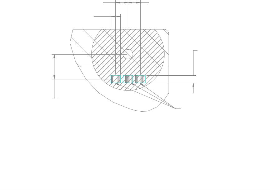
Figure 8. CPU and Memory Duct Keepout
Revision 1.2 |
25 |
|
Intel order number: D41763-003 |
Server Board Overview |
Intel® Server Boards S5000PSL and S5000XSL TPS |
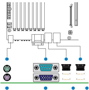
2.2.3Server Board ATX I/O Layout
The drawing below shows the layout of the rear I/O components for the server board.
A C E G
|
|
|
|
|
|
|
|
|
|
|
|
|
|
|
|
|
|
|
|
|
|
|
|
|
|
|
|
|
|
|
|
|
|
|
|
|
|
|
|
|
|
|
|
|
|
|
|
|
|
|
|
|
|
|
|
|
|
|
|
|
|
|
|
|
|
|
|
|
|
|
|
|
|
|
|
|
|
|
|
|
|
|
|
|
|
|
|
|
|
|
|
|
|
|
|
|
|
|
|
|
|
|
|
|
|
|
|
|
|
|
|
|
|
|
|
|
|
|
|
|
|
|
|
|
|
|
|
|
|
|
|
|
|
|
|
|
|
|
|
|
|
|
|
|
|
|
|
|
|
|
|
|
|
|
|
|
|
|
|
|
|
|
|
|
|
|
|
|
|
|
|
|
|
|
|
|
|
|
|
|
|
|
|
|
|
|
|
|
|
|
|
|
|
|
|
|
|
|
|
|
|
|
|
|
|
|
|
|
|
|
|
|
|
|
|
|
|
|
|
|
|
|
|
|
|
|
|
|
|
B |
D |
F |
H |
|||||||||||||
|
|
|
|
|
|
|
|
|
|
|
|
|
AF000222 |
|||||
|
|
|
|
|
|
|
|
|
|
|
||||||||
A. PS/2 mouse |
E. NIC port 1 (1 Gb) |
|
|
|
|
|
|
|
|
|
||||||||
|
|
|
|
|
||||||||||||||
B. PS/2 keyboard |
F. USB port 2 (top), 3 (bottom) |
|
|
|
||||||||||||||
|
|
|
|
|
|
|
|
|
|
|
||||||||
C. Serial port |
G. NIC port 2 (1 Gb) |
|
|
|
|
|
|
|
|
|
||||||||
|
|
|
|
|
||||||||||||||
D. Video |
H. USB port 0 (top), 1 (bottom) |
|
|
|
||||||||||||||
|
|
|
|
|
|
|
|
|
|
|
|
|
|
|
|
|
|
|
|
|
Figure 9. ATX I/O Layout |
|
|
|
26 |
Revision 1.2 |
|
|
|
Intel order number: D41763-003 |

Intel® Server Boards S5000PSL and S5000XSL TPS |
List of Tables |
3.Functional Architecture
The architecture and design of the Intel® Server Boards S5000PSL and S5000XSL are based on the Intel® S5000P and S5000X chipsets respectively. These chipsets are designed for systems that use the Intel® Xeon® processor with system bus speeds of 667 MHz, 1066 MHz, and 1333 MHz.
The chipset contains two main components: the Memory Controller Hub (MCH) for the host bridge and the I/O controller hub for the I/O sub-system. The chipset uses the Enterprise South Bridge (ESB2-E) for the I/O controller hub. This chapter provides a high-level description of the functionality associated with each chipset component and the architectural blocks that make up the server board.
For more information about the functional architecture blocks, see the Intel® S5000 Server Board Family Datasheet.
Revision 1.2 |
27 |
|
Intel order number: D41763-003 |

Server Board Overview |
Intel® Server Boards S5000PSL and S5000XSL TPS |
|
|
Figure 10. Functional Block Diagram |
|
|
|
28 |
Revision 1.2 |
|
|
|
Intel order number: D41763-003 |

Intel® Server Boards S5000PSL and S5000XSL TPS |
List of Tables |
3.1Intel® 5000P / 5000X Memory Controller Hub (MCH)
The Memory Controller Hub (MCH) is a single 1432-pin FCBGA package, which includes the following core platform functions:
System Bus Interface for the processor sub-system
Memory Controller
PCI-Express Ports including the Enterprise South Bridge Interface (ESI)
FBD Thermal Management
SMBUS Interface
This section provides a high-level overview of some of these core functions as they pertain to this server board. Additional information can be obtained from the Intel S5000 Server Board Family Datasheet and the Intel 5000 Series Chipset Memory Controller Hub Datasheet.
3.1.1System Bus Interface
The MCH is configured for symmetric multi-processing across two independent front side bus interfaces that connect to the DualCore Intel® Xeon® processors. Each front side bus on the MCH uses a 64-bit wide 667, 1066, or 1333-MHz data bus. The 1333-MHz data bus is capable of transferring data at up to 10.66 GB/s. The MCH supports a 36-bit wide address bus, capable of addressing up to 64 GB of memory. The MCH is the priority agent for both front side bus interfaces, and is optimized for one processor on each bus.
3.1.2Processor Support
The server board supports one or two Dual Core Intel® Xeon® processors 5000 sequence, with system bus speeds of 667 MHz, 1066 MHz, and1333 MHz, and core frequencies starting at 3.73 GHz. Previous generations of the Intel® Xeon® processor are not supported on this server board.
Note: Only Dual Core Intel® Xeon® processors 5000 Sequence that support system bus speeds of 667 MHz, 1066 MHz and 1333 MHz are supported on this server board. See the following table for a list of supported processors.
Table 2. Processor Support Matrix
|
Processor Family |
System Bus Speed |
Core Frequency |
Cache |
Watts |
Support |
|
|
|
|
Intel® Xeon® Processor 5030 |
667MHz |
2.67 GHz |
2x 2 MB |
95 |
Yes |
|
|
|
|
|
|
|
|
|
|
|
||
Revision 1.2 |
|
|
|
|
29 |
|
|||
Intel order number: D41763-003

Server Board Overview |
|
|
Intel® Server Boards S5000PSL and S5000XSL TPS |
|||||
|
|
|
|
|
|
|
|
|
|
Intel® Xeon® Processor 5050 |
667 MHz |
3.0 GHz |
|
2x 2 MB |
95 |
Yes |
|
|
Intel® Xeon® Processor 5060 |
1066 MHz |
3.2 GHz |
|
2x 2 MB |
130 |
Yes |
|
|
Intel® Xeon® Processor 5063 |
1066 MHz |
3.2 GHz |
|
2x 2 MB |
95 |
Yes |
|
|
Intel® Xeon® Processor 5080 |
1066 MHz |
3.73 GHz |
|
2x 2 MB |
130 |
Yes |
|
|
Intel® Xeon® Processor 5110 |
1066 MHz |
1.60 |
|
4 MB |
65 |
Yes |
|
|
Intel® Xeon® Processor 5120 |
1066 MHz |
1.86 |
|
4 MB |
65 |
Yes |
|
|
Intel® Xeon® Processor 5130 |
1333 |
2.00 |
|
4 MB |
65 |
Yes |
|
|
Intel® Xeon® Processor 5140 |
1333 |
2.33 |
|
4 MB |
65 |
Yes |
|
|
Intel® Xeon® Processor 5148 |
1333 |
2.33 |
|
4 MB |
40 |
Yes |
|
|
Intel® Xeon® Processor 5150 |
1333 |
2.66 |
|
4 MB |
65 |
Yes |
|
|
Intel® Xeon® Processor 5160 |
1333 |
3.00 |
|
4 MB |
80 |
Yes |
|
3.1.2.1Processor Population Rules
When two processors are installed, both must be of identical revision, core voltage, and bus/core speed. When only one processor is installed, it must be in the socket labeled CPU1. The other socket must be empty.
The board is designed to provide up to 130A of current per processor. Processors with higher current requirements are not supported.
No terminator is required in the second processor socket when using a single processor configuration.
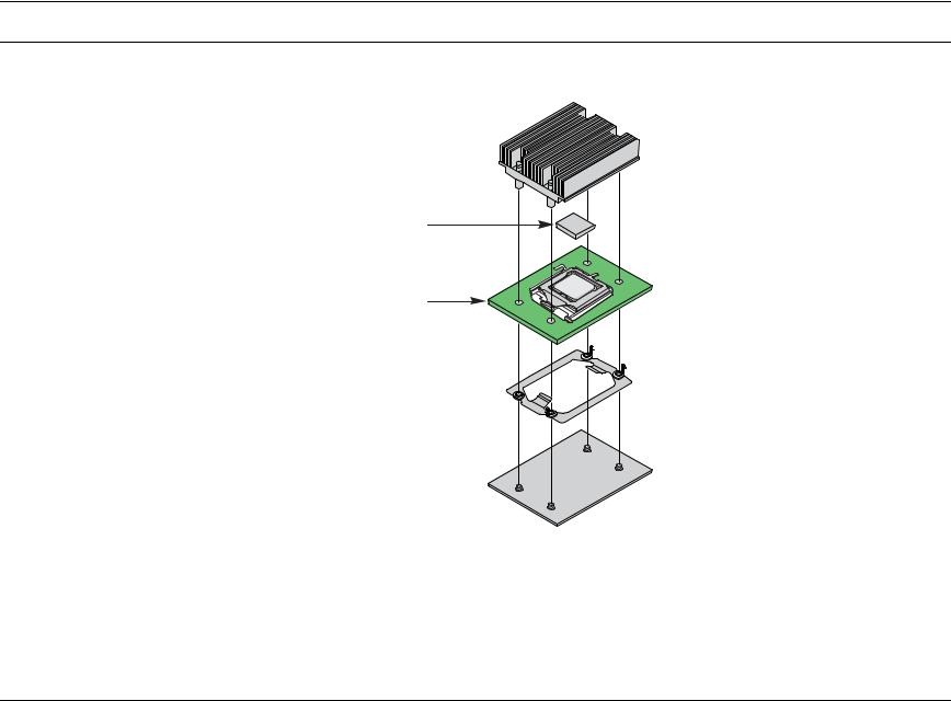
3.1.2.2Common Enabling Kit (CEK) Design Support
The server board complies with Intel’s Common Enabling Kit (CEK) processor mounting and heatsink retention solution. The server board ships with a CEK spring snapped onto the underside of the server board, beneath each processor socket. The heatsink attaches to the CEK, over the top of the processor and the thermal interface material (TIM). See the figure below for the stacking order of the chassis, CEK spring, server board, TIM, and heatsink.
The CEK spring is removable, allowing for the use of non-Intel heatsink retention solutions.
30 |
Revision 1.2 |
|
Intel order number: D41763-003 |
Intel® Server Boards S5000PSL and S5000XSL TPS |
List of Tables |
Note: The processor heat sink and CEK spring shown in the following diagram are for reference purposes only. The actual processor heat sink and CEK solutions compatible with this generation server board may be of a different design.
Heatsink assembly 
Thermal Interface
Material (TIM)
Server Board |
TP02091 |
|
CEK Spring 

Chassis 
AF000196
Figure 11. CEK Processor Mounting
Revision 1.2 |
31 |
|
Intel order number: D41763-003 |
 Loading...