


 Loading...
Intel® Server System R2000WT Product Family
System Integration and Service Guide
A Guide for Technically Qualified Assemblers of Intel identified Subassemblies/Products
Rev 1.2
April 2015
Intel®Server Boards and Systems

Intel® Server System R2000WT Product Family System Integration and Service Guide
Document Revision History
Date |
Revision |
Modifications |
||
Number |
||||
|
|
|
||
September 2014 |
1.0 |
First External Public Release |
|
|
|
|
|
|
|
December 2014 |
1.1 |
Chapter 5 added – System Packaging Assembly Instructions |
|
|
|
|
|
|
|
|
|
• Corrected accessory kit content list section 1.2 |
|
|
April 2015 |
1.2 |
• Updated Discalimer Statement |
|
|
|
|
• Changed server board mounting screw torque from 8 in-lbs to 12 in-lbs |
|
|
|
|
|
|
|
ii

Disclaimers
Intel technologies’ features and benefits depend on system configuration and may require enabled hardware, software or service activation. Learn more at Intel.com, or from the OEM or retailer.
You may not use or facilitate the use of this document in connection with any infringement or other legal analysis concerning Intel products described herein. You agree to grant Intel a non-exclusive, royalty-free license to any patent claim thereafter drafted which includes subject matter disclosed herein.
No license (express or implied, by estoppel or otherwise) to any intellectual property rights is granted by this document.
The products described may contain design defects or errors known as errata which may cause the product to deviate from published specifications. Current characterized errata are available on request.
Intel disclaims all express and implied warranties, including without limitation, the implied warranties of merchantability, fitness for a particular purpose, and non-infringement, as well as any warranty arising from course of performance, course of dealing, or usage in trade.
Intel, the Intel logo, Xeon, and Xeon Phi are trademarks of Intel Corporation in the U.S. and/or other countries.
*Other names and brands may be claimed as the property of others.
Copyright © 2015 Intel Corporation. All Rights Reserved.

Intel® Server System R2000WT Product Family System Integration and Service Guide
Safety Information
Important Safety Instructions
Read all caution and safety statements in this document before performing any of the instructions. See also Intel Server Boards and Server Chassis Safety Information at http://www.intel.com/support/motherboards/server/sb/cs-010770.htm.
Wichtige Sicherheitshinweise
Lesen Sie zunächst sämtliche Warnund Sicherheitshinweise in diesem Dokument, bevor Sie eine der Anweisungen ausführen. Beachten Sie hierzu auch die Sicherheitshinweise zu Intel-Serverplatinen und Servergehäusen auf der
http://www.intel.com/support/motherboards/server/sb/cs-010770.htm.
Consignes de sécurité
Lisez attention toutes les consignes de sécurité et les mises en garde indiquées dans ce document avant de suivre toute instruction. Consultez Intel Server Boards and Server Chassis Safety Information sur le site
http://www.intel.com/support/motherboards/server/sb/cs-010770.htm.
Instrucciones de seguridad importantes
Lea todas las declaraciones de seguridad y precaución de este documento antes de realizar cualquiera de las instrucciones. Vea Intel Server Boards and Server Chassis Safety Information en
http://www.intel.com/support/motherboards/server/sb/cs-010770.htm.
/ http://www.intel.com/support/motherboards/server/sb/cs-010770.htm Intel® Server Boards and Server Chassis Safety Information Intel
iv

Intel® Server System R2000WT Product Family System Integration and Service Guide
Warnings
Heed safety instructions: Before working with your server product, whether you are using this guide or any other resource as a reference, pay close attention to the safety instructions. You must adhere to the assembly instructions in this guide to ensure and maintain compliance with existing product certifications and approvals. Use only the described, regulated components specified in this guide. Use of other products/components will void the UL listing and other regulatory approvals of the product and will most likely result in noncompliance with product regulations in the region(s) in which the product is sold.
System power on/off: The power button DOES NOT turn off the system AC power. To remove power from the system, you must unplug the AC power cord from the wall outlet. Make sure the AC power cord is unplugged before you open the chassis, add, or remove any components.
Hazardous conditions, devices and cables: Hazardous electrical conditions may be present on power, telephone, and communication cables. Turn off the server and disconnect the power cord, telecommunications systems, networks, and modems attached to the server before opening it. Otherwise, personal injury or equipment damage can result.
Electrostatic discharge (ESD) and ESD protection: ESD can damage disk drives, boards, and other parts. We recommend that you perform all procedures in this chapter only at an ESD workstation. If one is not available, provide some ESD protection by wearing an antistatic wrist strap attached to chassis ground - any unpainted metal surface - on your server when handling parts.
ESD and handling boards: Always handle boards carefully. They can be extremely sensitive to ESD. Hold boards only by their edges. After removing a board from its protective wrapper or from the server, place the board component side up on a grounded, static free surface. Use a conductive foam pad if available but not the board wrapper. Do not slide board over any surface.
Installing or removing jumpers: A jumper is a small plastic encased conductor that slips over two jumper pins. Some jumpers have a small tab on top that you can grip with your fingertips or with a pair of fine needle nosed pliers. If your jumpers do not have such a tab, take care when using needle nosed pliers to remove or install a jumper; grip the narrow sides of the jumper with the pliers, never the wide sides. Gripping the wide sides can damage the contacts inside the jumper, causing intermittent problems with the function controlled by that jumper. Take care to grip with, but not squeeze, the pliers or other tool you use to remove a jumper, or you may bend or break the pins on the board.
v

Intel® Server System R2000WT Product Family System Integration and Service Guide
Preface
About this document
This document is written for system integrators and service technicians who are responsible for system assembly, server upgrades, server repair, and component replacement.
This document is divided into two major sections. The first half of the document provides detailed instructions on how to assemble a system from the bare chassis to a functional server. It will guide you through the installation of system components and available accessories. The second half of the document is focused on system service. It provides many reference diagrams used to identify all key physical features of the system. It also provides detailed instructions for the replacement of field replaceable components.
For the latest revision of this document, go to http://www.intel.com/support
Document Organization
System Integration
Chapter 1 –– Server Building Block System Integration – provides grounds up assembly instructions for the integration of individual server building blocks, starting with a bare chassis and installing all the system boards and major server components, including power supply and system fans. This chapter can be skipped if the server board and other major components are pre-installed in the system.
Chapter 2 – Essential System Component Integration and Service – provides instructions for adding essential system components required to complete the integration of the server system. This includes installation of Processors, Memory, Add-in Cards, and hot-swap storage devices
Chapter 3 – Options and Accessory Kit Integration and Service – provides instructions for adding and removing various system options and available accessory option kits that maybe installed in the system
Chapter 4 – System Software Updates and Configuration - provides instructions for completing the integration of the server system by updating the system software and navigating through the BIOS Setup screens.
Chapter 5 – System Packaging Assembly – Provides package assembly instructions when re-using the Intel packaging the system was originally shipped in.
System Service
Chapter 6 - System Features Overview – provides a high level overview of the Intel® Server System R2000WT product family. In this chapter, you will find a list of the server system features and illustrations identifying the major system components.
Chapter 7 – FRU Replacement – provides guidance for the replacement of system components considered as field replaceable units (FRUs).
Appendix A – Getting Help
Appendix B – System Cable Routing Diagrams
Appendix C – System Status LED Operating States and Definition Appendix D – POST Code Diagnostic LED Decoder Table Appendix E – POST Code Errors
vi
Intel® Server System R2000WT Product Family System Integration and Service Guide
Additional Information and Software
For additional information about this family of products or any of their supported accessories, refer to the following resources available at http://www.intel.com/support.
|
Table 1. Server System References |
|
For this information or |
Use this Document or Software |
|
software |
|
|
|
|
|
|
• Intel® Server Board S2600WT Technical Product Specification |
|
|
• Intel® Server System R2000WT Product Family Technical Product Specification |
|
|
• Intel® Remote Management Module 4 (Intel® RMM4) and Integrated BMC User Guide |
|
For in-depth technical |
• Intel® Remote Management Module 4 Technical Product Specification |
|
information about this |
• Intel® I/O Expansion Modules Hardware Specification |
|
product family |
• Intel® Server System BIOS Setup Utility Guide |
|
|
||
|
• Intel® Server Platform Firmware Specification Update |
|
|
• Product Safety and Regulatory Compliance - Intel® Xeon® Processor E5-2600 v3 |
|
|
http://www.intel.com/p/en_US/support/highlights/server/s2600wt?wapkw=s2600wt+family |
|
|
|
|
For system integration |
• Intel® Server System R2000WT product family System Integration and Service Guide |
|
instructions and service |
||
http://www.intel.com/p/en_US/support/highlights/server/s2600wt?wapkw=s2600wt+family |
||
guidance |
||
|
||
|
|
|
For server configuration |
Intel® S2600WT Product Family Configuration Guide rev 2.x |
|
Intel® Server Configurator tool |
||
guidance and compatibility |
||
http://serverconfigurator.intel.com |
||
|
||
|
|
|
For system power budget |
Intel® Server Board S2600WT Product Family Power Budget Tool and Thermal Configuration Guide |
|
guidance |
https://downloadcenter.intel.com/product/78562/Intel-Server-Board-S2600WT-Family |
|
|
|
|
For system firmware |
|
|
updates, onboard device |
|
|
drivers, and software to |
https://downloadcenter.intel.com/product/78562/Intel-Server-Board-S2600WT-Family |
|
manage your Intel® Server |
|
|
System. |
|
|
|
|
|
For a complete list of |
|
|
supported processors, |
http://www.intel.com/p/en_US/support/category/server/s2600wt/doc_guide# |
|
memory, add-in cards, and |
||
peripherals: |
|
|
|
|
The server system has support for several software utilities which can be used to configure system parameters and aid in troubleshooting system issues. All available utilities can be downloaded from the following Intel web site: http://downloadcenter.intel.com/
Table 2. System Utility Software
To do this: |
Use this utility: |
|
|
|
|
To obtain full system information |
Intel® SYSINFO Utility – Various OS support |
|
|
|
|
To read System Event Log (SEL) |
Intel® SELVIEW Utility – Various OS support |
|
|
|
|
Configure, Save and Restore various system options |
Intel® SYSCFG Utility – Various OS support |
|
|
|
|
Test onboard feature functionality |
Intel® Platform Confidence Test (PCT) – uEFI only |
|
|
|
|
To update system software |
• System Update Package (SUP) – uEFI only |
|
• Intel® One Boot Flash Update (OFU) – Various OS Support |
||
|
||
To configure and manage Intel® RAID Controllers |
Intel® RAID Web Console 2 Utility – Various OS support |
|
|
|
|
Server Management Software |
Intel® Active System Console |
|
|
|
vii

Intel® Server System R2000WT Product Family System Integration and Service Guide
Table of Contents
1. Server Building Block System Integration ....................................................................... |
1 |
|
1.1 |
Intel® Server Chassis Identification ........................................................................ |
3 |
1.2 |
Prepare Chassis for Assembly............................................................................... |
3 |
1.3 |
System Assembly .................................................................................................. |
6 |
1.3.18 x 2.5” Front Drive Bay Module Installation (Intel® Server Chassis R2000WTxxx and Intel®
Server System R2208WTxxxx) ............................................................................................ |
8 |
|
1.3.2 |
8 x 3.5” Front Drive Bay Module Installation (Intel® Server Chassis R2000WTxxxx Only) 10 |
|
1.3.3 |
Internal Cable Routing and Connections.............................................................. |
13 |
1.3.4 |
Power Supply Installation..................................................................................... |
20 |
2. Essential System Component Installation and Service................................................. |
21 |
|
2.1 |
Internal Cable Routing ......................................................................................... |
22 |
2.2 |
System Cover Removal / Installation ................................................................... |
23 |
2.2.1 |
System Cover Removal ....................................................................................... |
23 |
2.2.2 |
System Cover Installation .................................................................................... |
23 |
2.3 |
Air Duct Removal / Installation ............................................................................. |
24 |
2.3.1 |
Air Duct Removal................................................................................................. |
24 |
2.3.2 |
Air Duct Installation.............................................................................................. |
24 |
2.4 |
System Fan Assembly Removal / Installation ...................................................... |
25 |
2.4.1 |
System Fan Assembly Removal .......................................................................... |
25 |
2.4.2 |
System Fan Assembly Installation ....................................................................... |
26 |
2.5 |
Processor (CPU) Installation / Removal............................................................... |
27 |
2.5.1 |
Processor Heatsink(s) Removal........................................................................... |
27 |
2.5.2 |
Processor Installation........................................................................................... |
28 |
2.5.3 |
Processor Heatsink Installation............................................................................ |
31 |
2.5.4 |
Removing the Processor...................................................................................... |
31 |
2.6 |
Memory Installation and Removal........................................................................ |
32 |
2.6.1 |
Memory Slot population requirements.................................................................. |
32 |
2.6.2 |
DDR4 DIMM Installation ...................................................................................... |
32 |
2.6.3 |
Removing Memory............................................................................................... |
33 |
2.7 |
Storage Device Installation / Removal ................................................................. |
34 |
2.7.1 |
8 x 3.5” and 12 x 3.5” Front Drive Bay Storage .................................................... |
34 |
2.7.2 |
8 x 2.5”, 16 x 2.5”, and 24 x 2.5” Front Drive Bay Storage ................................... |
36 |
2.7.3 |
Internal Fixed Mount SATA SSD – Installation / Removal .................................... |
37 |
2.8 |
Riser Card Assembly - Removal / Integration / Installation................................... |
40 |
2.8.1 |
Riser Card Assembly Removal ............................................................................ |
40 |
2.8.2 |
Mounting a Riser Card Option to the Riser Bracket.............................................. |
41 |
2.8.3 |
PCI Add-in Card Installation................................................................................. |
41 |
2.8.4 |
PCI Riser Assembly Installation ........................................................................... |
42 |
2.9 |
Rack Handles – Installation / Removal................................................................. |
43 |
2.9.1 |
Installing the Rack Handles ................................................................................. |
43 |
2.9.2 |
Removing the Rack Handles................................................................................ |
43 |
3. Option and Accessory Kit Integration and Service ....................................................... |
44 |
|
3.1 |
Slimline Optical Drive – Installation and Removal ................................................ |
45 |
viii |
|
|
|
Intel® Server System R2000WT Product Family System Integration and Service Guide |
|
|
3.1.1 |
Slimline Optical Drive Installation......................................................................... |
45 |
|
3.1.2 |
Slimline Optical Drive Removal............................................................................ |
47 |
|
3.2 |
Power Supply Module – Installation / Removal .................................................... |
48 |
|
3.2.1 |
Power Supply Module Installation ........................................................................ |
48 |
|
3.2.2 |
Power Supply Module Removal ........................................................................... |
48 |
|
3.3 |
Power Cord Retention Strap Installation .............................................................. |
49 |
|
3.4 |
Intel® SAS RAID Module Installation / Removal .................................................. |
50 |
|
3.4.1 |
Intel® SAS RAID Module Installation ................................................................... |
50 |
|
3.4.2 |
Intel® SAS RAID Module Removal ...................................................................... |
50 |
|
3.5 |
Intel® I/O Expansion Module – Installation / Removal........................................... |
51 |
|
3.5.1 |
Intel® I/O Expansion Module Installation ............................................................. |
51 |
|
3.5.2 |
Intel® I/O Expansion Module Removal ................................................................ |
51 |
|
3.6 |
SATA RAID 5 Upgrade Key – Installation / Removal ........................................... |
52 |
|
3.6.1 |
Installing the SATA RAID 5 Upgrade Key ............................................................ |
52 |
|
3.6.2 |
Removing the SATA RAID 5 Upgrade Key .......................................................... |
52 |
|
3.7 |
Intel® Remote Management Module 4 Lite Key – Installation / Removal .............. |
53 |
|
3.7.1 |
Intel® RMM4 Lite Key Installation ....................................................................... |
53 |
|
3.7.2 |
Intel® RMM4 Lite Key Removal ........................................................................... |
53 |
|
3.8 |
Trusted Platform Module (TPM) Installation ......................................................... |
54 |
|
3.9 |
Front Bezel – Installation / Removal..................................................................... |
55 |
|
3.9.1 |
Bezel Snap-ons ................................................................................................... |
55 |
|
3.9.2 |
Front Bezel Installation ........................................................................................ |
56 |
|
3.9.3 |
Front Bezel Removal ........................................................................................... |
56 |
|
3.10 |
Intel® RAID Maintenance Free Backup Unit (RMFBU) – Mounting Bracket Installation |
57 |
|
3.11 |
2 x 2.5” Rear Mount Backplane Module Accessory Kit Installation..................... |
58 |
|
3.12 |
Intel® RAID Expander Card Installation ............................................................... |
61 |
|
3.12.1 |
2.5” Front Drive Bay Support ............................................................................... |
61 |
|
3.12.2 |
3.5” Front Drive Bay Support ............................................................................... |
62 |
|
3.12.3 |
Intel® RAID Expander Card Cabling Overview .................................................... |
63 |
|
3.13 |
R2208WT… to R2216WT… Upgrade .................................................................. |
64 |
|
3.14 |
R2208WTxxx / R2216WTxxx to R2224xxx Upgrade............................................ |
64 |
|
4. System Software Updates and Configuration................................................................ |
69 |
|
|
4.1 |
Updating the System Software Stack................................................................... |
69 |
|
4.2 |
Using the BIOS Setup Utility ................................................................................ |
69 |
|
4.2.1 |
Entering BIOS Setup ........................................................................................... |
69 |
|
4.2.2 |
No Access to the BIOS Setup Utility .................................................................... |
70 |
|
4.2.3 |
Navigating the BIOS Setup Utility ........................................................................ |
70 |
|
5. System Packaging Assembly Instructions..................................................................... |
72 |
|
|
5.1 |
Accessory Kit....................................................................................................... |
72 |
|
5.2 |
System Packaging Assembly Instructions............................................................ |
73 |
|
6. System Service - System Features Overview ................................................................ |
78 |
|
|
6.1 |
System Feature Reference Diagrams.................................................................. |
78 |
|
6.1.1 |
Front Drive Bay Options....................................................................................... |
79 |
|
6.1.2 |
Control Panel Features........................................................................................ |
80 |
|
6.1.3 |
Front I/O Features (Non-Storage Systems).......................................................... |
80 |
|
ix
|
Intel® Server System R2000WT Product Family System Integration and Service Guide |
|
6.1.4 |
Back Panel Features ........................................................................................... |
80 |
6.1.5 |
Server Board Features......................................................................................... |
81 |
6.2 |
System Configuration and Recovery Jumpers ..................................................... |
84 |
6.2.1 |
BIOS Default Jumper Block ................................................................................. |
84 |
6.2.2 |
Serial Port ‘A’ Configuration Jumper .................................................................... |
84 |
6.2.3 |
Password Clear Jumper Block ............................................................................. |
85 |
6.2.4 |
Management Engine (ME) Firmware Force Update Jumper Block....................... |
85 |
6.2.5 |
BMC Force Update Jumper Block........................................................................ |
86 |
6.2.6 |
BIOS Recovery Jumper ....................................................................................... |
86 |
7. System Service - FRU Replacement ............................................................................... |
88 |
|
7.1 |
Replacing the System Battery.............................................................................. |
89 |
7.2 |
Replacing the System Fan................................................................................... |
90 |
7.2.1 |
To remove a failed system fan............................................................................. |
90 |
7.2.2 |
To install a new system fan.................................................................................. |
90 |
7.3 |
Replacing the Standard Front Control Panel (R2308WTxxx) ............................... |
91 |
7.3.1 |
Standard Front Control Panel Removal (R2308WTxxx) ....................................... |
91 |
7.3.2 |
Standard Front Control Panel Installation (R2308WTxxx) .................................... |
92 |
7.4 |
Replacing the Standard Front Control Panel (R2208WTxxx & R2216WTxxx)...... |
93 |
7.4.1 |
Standard Front Control Panel Removal (R2208WTxxx & R2216WTxxx).............. |
93 |
7.4.2 |
Standard Front Control Panel Installation (R2208WTxxx & R2216WTxxx)........... |
95 |
7.5 |
Replacing the Server Board................................................................................. |
97 |
7.5.1 |
Server Board Removal......................................................................................... |
97 |
7.5.2 |
Server Board Installation...................................................................................... |
98 |
Appendix A: Getting Help ..................................................................................................... |
101 |
|
Appendix B: System Cable Routing Diagrams...................................................................... |
102 |
|
Appendix C: System Status LED Operating States and Definition....................................... |
108 |
|
Appendix D: POST Code Diagnostic LED Decoder Table..................................................... |
110 |
|
Appendix E: POST Code Errors............................................................................................. |
116 |
|
x
Intel® Server System R2000WT Product Family System Integration and Service Guide |
|
List of Figures |
|
Figure 1. Intel® Server Chassis R2312WTxxx – 12 x 3.5” Front Drive Bay.............................................. |
3 |
Figure 2. Intel® Server Chassis R2000WTxxx – No Front Drive Bay Installed ....................................... |
3 |
Figure 3. Chassis Components ................................................................................................................................. |
4 |
Figure 4. System Fan Assembly Removal ............................................................................................................ |
5 |
Figure 5. Server Board Installation ......................................................................................................................... |
6 |
Figure 6. Air Duct Side Wall Installation ............................................................................................................... |
7 |
Figure 7. R2000WTxxx Drive Bay Retention Bracket Removal ................................................................... |
8 |
Figure 8. 8 x 2.5" Drive Bay Module Installation................................................................................................ |
9 |
Figure 9. R2000WTxxx Drive Bay Retention Bracket Installation .............................................................. |
9 |
Figure 10. Control Panel and Front I/O Panel Removal from I/O Bay Module.................................. |
11 |
Figure 11. Front Control Pane and Front I/O Panel Installation into 8x3.5” Drive Bay Module. 12 |
|
Figure 12. 8x3.5" Front Drive Bay Module Installation............................................................................... |
13 |
Figure 13. 8x3.5" Front Drive Bay Retention Clip Installation .................................................................. |
13 |
Figure 14. Cable Routing Diagram ....................................................................................................................... |
14 |
Figure 15. R2312WTxxx Front Control Panel and Front I/O Internal Cable Connections............ |
15 |
Figure 16. R2000WTxxx Front Control Panel and Front I/O Internal Cable Connections............ |
16 |
Figure 17. Hot Swap Backplane Connectors ................................................................................................... |
17 |
Figure 18. Hot Swap Backplane Power Cable Installation......................................................................... |
17 |
Figure 19. Hot Swap Backplane I2C Cable......................................................................................................... |
18 |
Figure 20. Hot Swap Backplane I2C Internal Cable Connection ............................................................. |
18 |
Figure 21. Dual 8x2.5" Hot Swap Backplane I2C Jumper Cable Installation...................................... |
19 |
Figure 22. On-Board Mini-SAS HD Connectors for embedded SATA Support................................. |
20 |
Figure 23. Power Supply and Power Supply Bay Filler Installation....................................................... |
20 |
Figure 24. Internal Cable Routing......................................................................................................................... |
22 |
Figure 25. Air Duct Removal ................................................................................................................................... |
24 |
Figure 26. Air Duct Installation.............................................................................................................................. |
24 |
Figure 27. System Fan Assembly Removal....................................................................................................... |
25 |
Figure 28. System Fan Assembly Installation ................................................................................................. |
26 |
Figure 29. Processor Heatsink Removal – Shown with NO processor installed............................... |
27 |
Figure 30. Processor Installation – Open the Socket Lever ...................................................................... |
28 |
Figure 31. Processor Installation– Open the Load Plate ............................................................................ |
28 |
Figure 32. Processor Installation – Install the Processor ........................................................................... |
29 |
Figure 33. Processor Installation – Remove the Socket Cover ................................................................ |
29 |
Figure 34. Processor Installation – Close the Load Plate ........................................................................... |
30 |
Figure 35. Processor Installation – Latch the Locking Lever..................................................................... |
30 |
xi
Intel® Server System R2000WT Product Family System Integration and Service Guide |
|
Figure 36. Processor Heatsink Installation....................................................................................................... |
31 |
Figure 37. DIMM Blank.............................................................................................................................................. |
32 |
Figure 38. DDR4 DIMM Installation...................................................................................................................... |
32 |
Figure 39. DDR4 DIMM Removal........................................................................................................................... |
33 |
Figure 40. Installing Hot-swap storage devices – 3.5” carrier extraction ............................................ |
34 |
Figure 41. 3.5” Hard Disk Drive Installation – Remove the drive blank................................................ |
34 |
Figure 42. 3.5” Hard Disk Drive Installation – Mounting drive to carrier.............................................. |
35 |
Figure 43. Option to install 2.5” SSD into a 3.5” carrier.............................................................................. |
35 |
Figure 44. Hard Disk Drive Installation – Inserting 3.5” HDD assembly ............................................... |
36 |
Figure 45. Installing Hot-swap storage devices – 2.5” carrier extraction ............................................ |
36 |
Figure 46. 2.5” Storage Device Installation – Remove the drive blank................................................. |
37 |
Figure 47. 2.5” Storage Device Installation – Mount Drive to Carrier.................................................... |
37 |
Figure 48. 2.5” Storage Device Installation – Inserting 2.5” Drive assembly...................................... |
37 |
Figure 49. Peripheral Device Power Cable ....................................................................................................... |
38 |
Figure 50. Internal fixed mount SSD Installation........................................................................................... |
39 |
Figure 51. Removing an internal fixed mount SSD ....................................................................................... |
39 |
Figure 52. Riser Card Bracket Assemblies ........................................................................................................ |
40 |
Figure 53. PCI Riser Assembly Removal ............................................................................................................ |
40 |
Figure 54. Riser Card Installation to Riser Bracket........................................................................................ |
41 |
Figure 55. PCI Add-In Card Installation ............................................................................................................. |
41 |
Figure 56. Installing PCI Riser Assembly ........................................................................................................... |
42 |
Figure 57. Installing the Rack Handle ................................................................................................................. |
43 |
Figure 58. Installing the Plastic Mounting Clip to an Optical Drive........................................................ |
45 |
Figure 59. Peripheral Power Connector ............................................................................................................ |
45 |
Figure 60. 7-pin Single SATA Port Connectors .............................................................................................. |
46 |
Figure 61. Optical Drive Installation.................................................................................................................... |
46 |
Figure 62. Removing the Slimline Optical Drive............................................................................................. |
47 |
Figure 63. Power Supply Module Installation ................................................................................................. |
48 |
Figure 64. Power Supply Module Removal ...................................................................................................... |
48 |
Figure 65. Power Cord Retention Strap Installation..................................................................................... |
49 |
Figure 66. Intel® SAS RAID Module Installation.............................................................................................. |
50 |
Figure 67. Installing Intel® I/O Expansion Module.......................................................................................... |
51 |
Figure 68. Removing an I/O Expansion Module............................................................................................. |
51 |
Figure 69. Installing the SATA RAID 5 Upgrade Key..................................................................................... |
52 |
Figure 70. Installing the Intel® RMM4 Lite ......................................................................................................... |
53 |
Figure 71. Trusted Platform Module (TPM) Installation ............................................................................. |
54 |
Figure 72. Installing the Snap-on to the front bezel .................................................................................... |
55 |
xii
Intel® Server System R2000WT Product Family System Integration and Service Guide |
|
Figure 73. Removing the Snap-on from the front bezel............................................................................. |
55 |
Figure 74. Installing the Front Bezel ................................................................................................................... |
56 |
Figure 75. Removing the Front Bezel.................................................................................................................. |
56 |
Figure 76. Intel® RMFBU Installation................................................................................................................... |
57 |
Figure 77. 2 x 2.5" Rear Mount Backplane Module Installation............................................................... |
58 |
Figure 78. Rear Backplane Cable Connectors................................................................................................. |
59 |
Figure 79. Rear HSBP Power Cable - iPN G99319......................................................................................... |
59 |
Figure 80. Rear HSBP I2C Cable – iPN H41333 .............................................................................................. |
60 |
Figure 81. Rear HSBP SATA & SGPIO Cable Bundle – iPN H41068 ....................................................... |
60 |
Figure 82. SAS Expander Mezzanine Card Installation ............................................................................... |
61 |
Figure 83. 12 Gb Intel® RAID Expander Card RES3FV288 Connector Identification ...................... |
63 |
Figure 84. Internal 12 Gb Intel® RAID Expander Card RES3TV360 - Connector Identification |
|
Block Diagram ...................................................................................................................................................... |
63 |
Figure 85. Package Assembly Orientation Reference Diagram ............................................................... |
73 |
Figure 85. Intel® Server System R2000WT Features Overview................................................................ |
78 |
Figure 86. No Front Drive Bay Configuration - Chassis only building block (Intel® Server Chassis |
|
R2000WTXXX) ..................................................................................................................................................... |
79 |
Figure 87. 8 x 3.5" Drive Bay Configuration (R2308WT….)........................................................................ |
79 |
Figure 88. 12 x 3.5" Drive Bay Configuration (R2312WT… – Storage System – Chassis only and |
|
System).................................................................................................................................................................... |
79 |
Figure 89. 8 x 2.5" Drive Bay Configuration (R2208WT….)......................................................................... |
79 |
Figure 90. 16 x 2.5" Drive Bay Configuration (R2216WT….)...................................................................... |
79 |
Figure 91. 24 x 2.5" Drive Bay Configuration (R2224WT…. – Storage System)................................. |
79 |
Figure 92. Control Panel Features........................................................................................................................ |
80 |
Figure 93. Front I/O Panel Features .................................................................................................................... |
80 |
Figure 94. Back Panel Features ............................................................................................................................. |
80 |
Figure 95. Server Board Feature Identification............................................................................................... |
81 |
Figure 96. Intel® Light-Guided Diagnostic LEDs - Server Board............................................................... |
82 |
Figure 97. DIMM Fault LEDs.................................................................................................................................... |
83 |
Figure 98. System Configuration and Recovery Jumpers.......................................................................... |
84 |
Figure 99. Replacing the Backup Battery .......................................................................................................... |
89 |
Figure 100. System Fan Installation.................................................................................................................... |
90 |
Figure 101. Server Board Removal ...................................................................................................................... |
97 |
Figure 102. Server Board Installation................................................................................................................. |
98 |
Figure 103. Air Duct Sidewall Installation......................................................................................................... |
99 |
Figure 104. System Cable Routing Channels ............................................................................................... |
102 |
Figure 105. Intel® Server System R2208WTxxxx - Cable Routing Diagram..................................... |
103 |
Figure 106. Intel® Server System R2216WTxxxx - Cable Routing Diagram..................................... |
104 |
xiii
Intel® Server System R2000WT Product Family System Integration and Service Guide
Figure 107. Intel® Server System R2224WTxxxx - Cable Routing Diagram..................................... |
105 |
Figure 108. Intel® Server System R2308WTxxxx - Cable Routing Diagram..................................... |
106 |
Figure 109. Intel® Server System R2312WTxxxx - Cable Routing Diagram..................................... |
107 |
Figure 110. POST Diagnostic LED Location .................................................................................................. |
110 |
xiv

Intel® Server System R2000WT Product Family System Integration and Service Guide
List of Tables |
|
Table 1. Server System References...................................................................................................................... |
vii |
Table 2. System Utility Software............................................................................................................................ |
vii |
Table 3. BIOS Setup: Keyboard Command Bar .............................................................................................. |
70 |
Table 4. System Status LED State Definitions.............................................................................................. |
108 |
Table 5. POST Progress Code LED Example................................................................................................. |
110 |
Table 6. MRC Progress Codes............................................................................................................................. |
111 |
Table 7. MRC Fatal Error Codes ......................................................................................................................... |
112 |
Table 8. POST Progress Codes........................................................................................................................... |
113 |
Table 9. POST Error Codes and Messages .................................................................................................... |
116 |
Table 10. POST Error Beep Codes.................................................................................................................... |
121 |
Table 11. Integrated BMC Beep Codes ........................................................................................................... |
122 |
xv
Intel® Server System R2000WT Product Family System Integration and Service Guide
< Blank Page>
xvi

Intel® Server System R2000WT Product Family System Integration and Service Guide
1. Server Building Block System Integration
Purpose
This chapter provides instructions for the integration of the following Intel server building blocks:
Intel® Server Chassis R2312WTxxx
+Intel® Server Board S2600WT (iPC S2600WT2 or iPC S2600WTT)
Intel® Server Chassis R2000WTxxx
+Intel® Server Board S2600WT (iPC S2600WT2 or iPC S2600WTT)
+8 x 2.5” Front Drive Bay Accessory Kit Options
or
+ 8 x 3.5” Front Drive Bay Accessory Kit Option
If your system came with the server board pre-installed in the chassis, you can skip this chapter and proceed to Chapter 2 - Essential System Component Installation and Service to continue the system integration.
In addition to the Intel Server building blocks defined above, the following system components (NOT included) will also be needed to complete the full system integration:
•Appropriate SAS/SATA Data Cables
•Appropriate Riser Card(s)
•Appropriate Power Supply Module(s)
•Intel® Xeon® processor E5-2600 v3 product family
•DDR4 memory
•Appropriate Power Cable
•Desired Storage Devices
•Desired Optional Server Accessories
For a complete list of supported Intel system components and accessories, please reference the following Intel documents:
•Intel® S2600WT Product Family Configuration Guide rev 2.x
Before You Begin
Before working with your server product, observe the safety and ESD precautions found in the Warnings section at the beginning of this manual.
Tools and Supplies Needed
•Anti-static wrist strap and conductive foam pad (recommended)
•Phillips* (cross head) screwdriver (#1 and #2 bits)
System Reference
All references to left, right, front, top, and bottom assume the reader is facing the front of the chassis.
1

Intel® Server System R2000WT Product Family System Integration and Service Guide
Instruction Format
Each procedure described in this chapter will follow an illustration first format. This format will give the reader the option to follow a quicker path to system integration by first seeing an illustration of the intended procedure. If necessary, the reader can then follow the step-by-step instructions that will accompany each procedure.
System Integration Advisory Note
It is highly recommended that the system integration process defined in the following sections within this chapter be performed in the order specified. Following these instructions will result in the proper installation of critical system components and provide recommended cable routing. Deviating from the prescribed process may result in improper system assembly, a longer integration process, and a less than desired system appearance.
2

Intel® Server System R2000WT Product Family System Integration and Service Guide
1.1 Intel® Server Chassis Identification
Figure 1. Intel® Server Chassis R2312WTxxx – 12 x 3.5” Front Drive Bay
Figure 2. Intel® Server Chassis R2000WTxxx – No Front Drive Bay Installed
1.2 Prepare Chassis for Assembly
As received, the Intel Server Chassis will include several components within a boxed accessory kit or placed within the chassis.
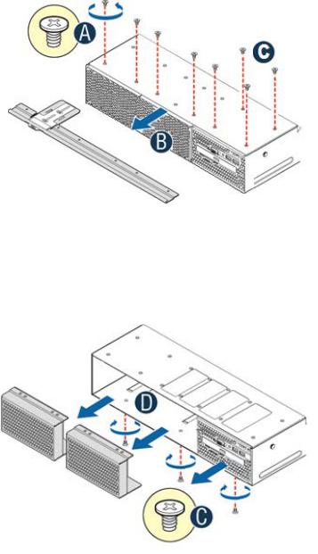
Remove the System Cover
Note: A non-skid surface or a stop behind the server system may be needed to prevent the server system from sliding on your work surface.
R2312WTxxxx |
R2000WTxxxx |
•Remove the top cover screws (see letter "A").
•Loosen the two captive thumb screws located on the back edge of the system cover (See letter “B”)
•Slide cover back and lift upward (see letter "C").
3
Intel® Server System R2000WT Product Family System Integration and Service Guide
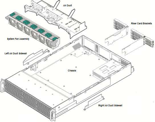
Chassis Component Identification
Figure 3. Chassis Components
The accessory kit and or system packaging will include the following components:
•The left and right black plastic air duct side walls
•Optical drive power cable and mounting clip
•Separate bags of screws for mounting the server board and riser card assembly
•RAID Maintenance Free Backup Unit (RMFBU) mounting plate and screws
•DIMM Blanks
•2 black mylar processor socket spacers
•Note: spare screws included in kit.
The chassis will include the following components. Each should be removed:
•Clear plastic air duct
•A box with two processor heat sinks
•Two riser card brackets
•The system fan assemby
4
Intel® Server System R2000WT Product Family System Integration and Service Guide
To remove the fan assembly:
•Lift the latches located on each end of the fan assembly until each latch is fully disengaged from the latch receivers on the chassis side wall.
•Grasp each end of the fan assembly and pull straight up until the assembly is fully disengaged from the assembly receivers on the chassis side wall.
•Carefully place the fan assembly face down onto a flat surface. Do NOT rest the fan assembly on the fan
connectors located on the bottom side of the fan assembly. Doing so may damage the connectors.
Figure 4. System Fan Assembly Removal
5
Intel® Server System R2000WT Product Family System Integration and Service Guide
1.3 System Assembly
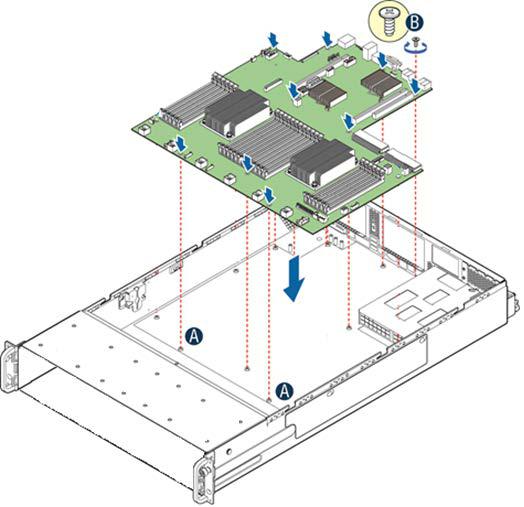
Server Board Installation
Figure 5. Server Board Installation
Note: Follow ESD precautions outlined at the beginning of this manual
•Clear the area for server board placement by carefully moving aside any cables that may be taped to the chassis base
•Remove the server board from its anti-static bag
•Holding the server board by its edges, carefully lower the server board into the chassis so that the rear I/O connectors of the server board align with and are fully seated into the matching holes on the chassis back panel and each server board mounting hole is aligned with a threaded chassis standoff.
•The server board is accurately placed when the two end screw holes nearest the front edge of the server board (See letter “A”) sit securely onto the shouldered chassis standoffs
•Using 12 in-lbs torque, fasten down the server board with 9 screws in the positions shown in Figure 5
6
Intel® Server System R2000WT Product Family System Integration and Service Guide
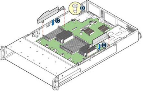
Air Duct Side Wall Installation
Figure 6. Air Duct Side Wall Installation
•Locate the two black plastic air duct sidewalls
•Following the illustration above, fasten down the appropriate air duct side wall onto each side of the server board using 8 in/lbs torque for each screw. (See letter “C”)
7
Intel® Server System R2000WT Product Family System Integration and Service Guide
1.3.18 x 2.5” Front Drive Bay Module Installation (Intel® Server Chassis
R2000WTxxx and Intel® Server System R2208WTxxxx)
Continue with the instructions in this section for installation of several available 8 x 2.5” front drive bay accessory kits into the system. If an 8 x 3.5” front drive bay module accessory kit is being installed, proceed to section 1.3.4.
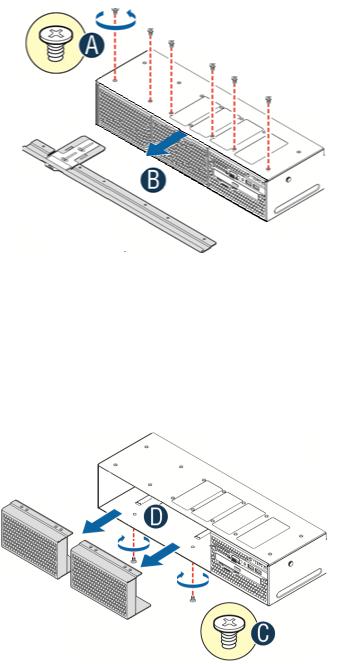
Remove Drive Bay Retention Bracket
Figure 7. R2000WTxxx Drive Bay Retention Bracket Removal
•To extract the drive bay retention bracket, remove the 6 fastener screws from the top front edge of the drive bay and pull out the metal bracket. Set aside the retention bracket and screws for re-installation at a later time.
Remove Drive Bay Filler Panel(s)
The chassis includes a drive bay filler panel for each drive bay location that doesn’t have a drive bay preinstalled. Remove a filler panel for each 8 x 2.5” drive bay module being installed.
•Carefully place the chassis on its side.
•From the bottom of the chassis, remove the fastener screw securing the drive bay filler panel (see letter ‘C’)
•Carefully return the chassis to its original position
•Slide out the drive bay filler panel (see letter ‘D’)
8

Intel® Server System R2000WT Product Family System Integration and Service Guide
Insert 8 x 2.5” drive bay module
Figure 8. 8 x 2.5" Drive Bay Module Installation
•Carefully unpackage the 8 x 2.5” drive bay module from the accessory kit
•Slide the 8 x 2.5” drive bay module into the server chassis (see letter ‘D’).
•Using two fastener screws on the top back edge of the drive bay, secure the drive bay to the chassis (See Letter ‘E’) (8 in/lbs torque for each screw)
•Repeat steps 1-3 for the second drive bay module (if applicable)
•Carefully place the chassis on its side and secure each installed drive bay module with one additional screw on the bottom of the chassis (see letter ‘F’). (8 in/lbs torque for each screw)
•Carefully return the chassis to its original position
Install Drive Bay Retention Bracket
Figure 9. R2000WTxxx Drive Bay Retention Bracket Installation
•Locate the drive bay retention bracket and screws
•Carefully slide the drive bay retention bracket into the gap between the top of the drive bay module(s) and the bottom of the drive bay sheet metal. (see letter ‘A’).
•Secure the retention bracket with six fastener screws (see letter ‘B’). (8 in/lbs torque for each screw)
•Continue to section 1.3.5
9
Intel® Server System R2000WT Product Family System Integration and Service Guide
1.3.28 x 3.5” Front Drive Bay Module Installation (Intel® Server Chassis
R2000WTxxxx Only)
This section describes the installation of Intel Accessory Kit A2U8X35S3HSDK into an Intel® Server Chassis R2000WTxxxx. Skip this section if your chassis already has a drive bay installed.
Remove Drive Bay Retention Bracket and I/O Bay Module Retention Screws
•To extract the drive bay retention bracket, remove the 6 fastener screws from the top front edge of the drive bay (See Letter ‘A’) and pull out the metal bracket (see letter ‘B’)
•Remove the 2 fastener screws from the back edge of the drive bay over the I/O Bay Module (see letter ‘C’)
Remove Drive Bay Filler Panels and I/O Bay Module
•Carefully place the chassis on its side
•From the bottom of the chassis, remove the fastener screws securing the drive bay filler panels and I/O Bay Module (see letter ‘C’)
•Carefully return the chassis to its original position
•Slide out the drive bay filler panels (see letter ‘D’)
•Carefully slide out the I/O Bay Module. Cables do not need to be disconnected from the I/O Bay Module
10
Intel® Server System R2000WT Product Family System Integration and Service Guide
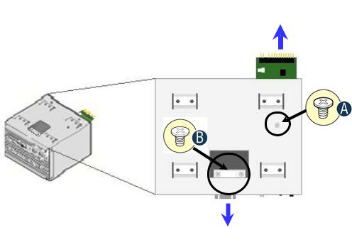
Remove Front Control Panel and Front I/O Panel from I/O Bay Module
Front Control Panel Board
Front I/O Panel
Figure 10. Control Panel and Front I/O Panel Removal from I/O Bay Module
Note: For this extraction process, the cables do not need to be detached from the assemblies
•Remove the Front Control Panel fastener screw located on the top right side of the I/O module bay (see letter ‘A’)
•Carefully extract the Front Control Panel assembly by pulling it out from the back of the I/O Module Bay
•Remove the two Front I/O Panel fastener screws accessed from the top center of the I/O Module (see letter ‘B’)
•Carefully extract the I/O panel assembly from the front of the I/O module bay. Feed the cables forward from the back of the I/O module bay as you pull out the I/O panel assembly
11
Intel® Server System R2000WT Product Family System Integration and Service Guide
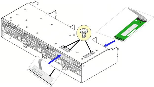
Install Front Control Panel Assembly and I/O Panel Assembly into 8 x 3.5” Front Drive Bay Module
Control Panel
Assembly
I/O Panel
Assembly
Figure 11. Front Control Pane and Front I/O Panel Installation into 8x3.5” Drive Bay Module
•Remove the 8 x 3.5” Drive Bay Module from its packaging
•Insert the Control Panel board into the back of the drive bay module as shown in Figure 9.
Note: Ensure the plastic gasket over the control panel buttons is securely in place before installing the control panel board into the drive bay module
•The control panel is properly positioned when the buttons are protruding from the Control Panel face plate on the front of the drive bay module and the screw holes on the top of the assembly are aligned.
•Using a single screw, secure the Control Panel Assembly to the drive bay module (8 in/lbs torque)
•Ensure the Control Panel cable is securely attached to the control panel board
•Carefully feed the Black USB cable and Grey ribbon cable of the I/O Panel Assembly into the I/O Panel slot on the front of the drive bay module. Cables should come out the back of the drive bay
•Position the I/O panel assembly into the I/O panel slot
•Ensure the screw holes on the top of the drive bay module and the I/O panel assembly are aligned
•Secure the assembly using two fastener screws (8 in/lbs torque)
12
Intel® Server System R2000WT Product Family System Integration and Service Guide
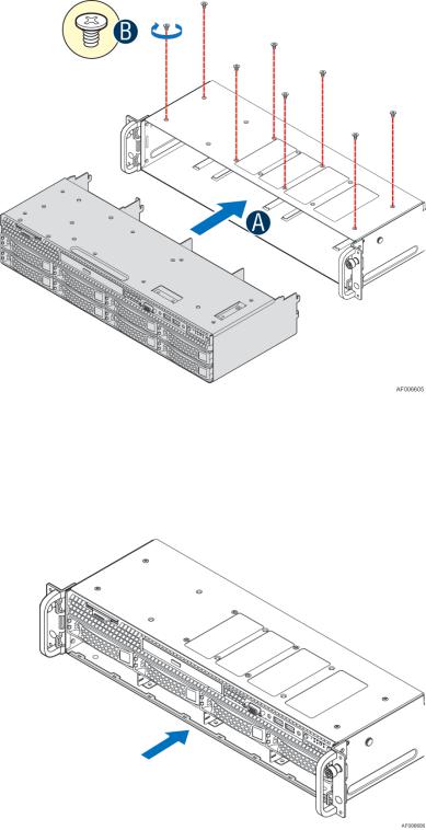
Install 8 x 3.5” Front Drive Bay Module into Chassis
Figure 12. 8x3.5" Front Drive Bay Module Installation
•Remove the bottom four drive trays from the drive bay module
•Slide the 8 x 3.5” Front Drive Bay module into the front of the chassis (see letter ‘A’)
•Push the drive bay module in far enough so that the screw holes on the top of the drive bay are properly aligned
•Using 8 fastener screws, secure the drive bay module to the chassis (8 in/lbs torque) (see letter ‘B’)
•Locate the drive bay retention clip
Figure 13. 8x3.5" Front Drive Bay Retention Clip Installation
•Slide the drive bay retention clip over the bottom edge of the drive bay assembly as shown in the illustration. The retention clip should clamp together the bottom of the drive bay module to the chassis base.
1.3.3Internal Cable Routing and Connections
13
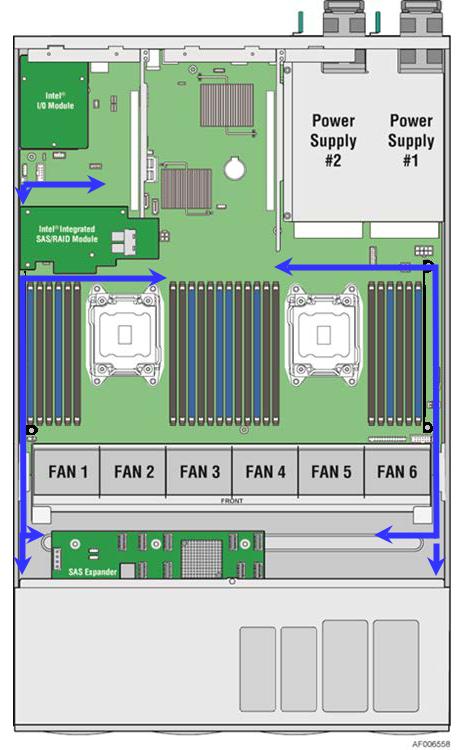
Intel® Server System R2000WT Product Family System Integration and Service Guide
All cables in the system that need to be routed from front-to-back, should be routed using the cable channels between the chassis sidewalls and the air duct sidewalls as shown in the following illustration. When routing cables front-to-back, none should be routed through the center of the system or in the area between the system fans and the DIMM slots. Cable connection instructions provided in this section are presented in the recommended order in which they should be installed. See Appendix B for additional System Cable routing illustrations.
Figure 14. Cable Routing Diagram
Connect Internal Cables for Front Control Panel and Front I/O
14
Loading...