


Operating Manual
Inverted Magnetron Pirani Gauge
MPG400 MPG401
tina48e1-b (2008-10) |
1 |
Product Identification
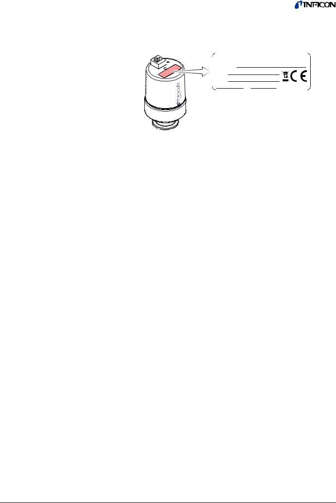
In all communications with INFICON, please specify the information given on the product nameplate. For convenient reference copy that information into the space provided below:
INFICON AG, LI-9496 Balzers
Model:
PN:
SN:
V W
Validity |
This document applies to products with part number: |
|||||
|
|
MPG400 (FPM sealed) |
|
MPG401 (all-metal) |
||
|
|
|
||||
|
351-010 |
(DN 25 ISO-KF) |
|
351-020 |
(DN 25 ISO-KF) |
|
|
351-011 |
(DN 40 ISO-KF) |
|
351-021 |
(DN 40 ISO-KF) |
|
|
351-012 |
(DN 40 CF-C) |
|
351-022 |
(DN 40 CF-C) |
|
Intended Use
Functional Principle
The part number (PN) can be taken from the product nameplate.
If not indicated otherwise in the legends, the illustrations in this document correspond to the product with part number 351-010. They apply to the other products by analogy.
We reserve the right to make technical changes without prior notice.
All dimensions in mm.
The Inverted Magnetron Pirani Gauges MPG400 und MPG401 has been designed for vacuum measurement in the pressure range of 5×10⁻⁹ … 1000 mbar.
The Inverted Magnetron Pirani Gauges must not be used for measuring flammable or combustible gases which react in air.
The gauges can be used with the Single-Channel Controller VGC401, the Two-Channel Controller VGC402 and the Three-Channel Controller VGC403 or with another evaluation unit.
Over the whole measuring range, the measuring signal is output as a logarithm of the pressure.
The gauge consists of two separate measuring systems (the Pirani and the cold cathode system according to the inverted magnetron principle). They are combined in such a way that for the user, they behave like one measuring system
2 |
tina48e1-b (2008-10) MPG400-401.om |

Contents
Product Identification |
2 |
|||
Validity |
2 |
|||
Intended Use |
2 |
|||
Functional Principle |
2 |
|||
1 |
Safety |
4 |
||
1.1 |
Symbols Used |
4 |
||
1.2 |
Personnel Qualifications |
4 |
||
1.3 |
General Safety Instructions |
4 |
||
1.4 |
Liability and Warranty |
5 |
||
2 |
Technical Data |
6 |
||
3 |
Installation |
9 |
||
3.1 |
Vacuum Connection |
9 |
||
3.1.1 Removing the Magnet Unit (Only for Gauges With CF Flanges) |
11 |
|||
3.2 |
Electrical Connection |
12 |
||
3.2.1 Use With an INFICON Controller |
12 |
|||
3.2.2 Use With Another Control Device |
12 |
|||
4 |
Operation |
13 |
||
4.1 |
Measurement Principle, Measuring Behavior |
13 |
||
5 |
Deinstallation |
15 |
||
6 |
Maintenance |
16 |
||
6.1 |
Adjusting the Gauge |
16 |
||
6.2 |
Cleaning MPG400, Replacing Parts |
18 |
||
6.2.1 |
Disassembling MPG400 |
18 |
||
6.2.2 |
Cleaning MPG400 |
19 |
||
6.2.3 |
Reassembling MPG400 |
20 |
||
6.3 |
Cleaning MPG401, Replacing Parts |
21 |
||
6.3.1 |
Disassembling MPG401 |
22 |
||
6.3.2 |
Cleaning MPG401 |
23 |
||
6.3.3 |
Reassembling MPG401 |
24 |
||
6.4 |
Troubleshooting |
25 |
||
7 |
Accessories |
26 |
||
8 |
Spare Parts |
26 |
||
9 |
Returning the Product |
28 |
||
10 |
|
Disposal |
28 |
|
Appendix |
29 |
|||
A: |
|
Measuring Signal vs. Pressure |
29 |
|
B: |
|
Gas Type Dependence |
30 |
|
Declaration of Contamination |
32 |
|||
For cross-references within this document, the symbol (→ XY) is used.
tina48e1-b (2008-10) MPG400-401.om |
3 |

1 Safety
1.1 Symbols Used
DANGER
Information on preventing any kind of physical injury.
WARNING
Information on preventing extensive equipment and environmental damage.
Caution
Information on correct handling or use. Disregard can lead to malfunctions or minor equipment damage.
1.2Personnel Qualifications
1.3General Safety Instructions
Skilled personnel
All work described in this document may only be carried out by persons who have suitable technical training and the necessary experience or who have been instructed by the end-user of the product.
•Adhere to the applicable regulations and take the necessary precautions for the process media used.
Consider possible reactions between the materials (→ 7) and the process media.
Consider possible reactions (e.g. explosion) of the process media due to the heat generated by the product.
•Adhere to the applicable regulations and take the necessary precautions for all work you are going to do and consider the safety instructions in this document.
•Before beginning to work, find out whether any vacuum components are contaminated. Adhere to the relevant regulations and take the necessary precautions when handling contaminated parts.
DANGER
DANGER: magnetic fields
Strong magnetic fields can disturb electronic devices like heart pacemakers or impair their function.
Maintain a safety distance of ≥10 cm between the magnet and the heart pacemaker or prevent the influence of strong magnetic fields by antimagnetic shielding.
Communicate the safety instructions to all other users.
4 |
tina48e1-b (2008-10) MPG400-401.om |

1.4 Liability and Warranty
INFICON assumes no liability and the warranty becomes null and void if the enduser or third parties
•disregard the information in this document
•use the product in a non-conforming manner
•make any kind of interventions (modifications, alterations etc.) on the product
•use the product with accessories not listed in the corresponding product documentation.
The end-user assumes the responsibility in conjunction with the process media used.
Gauge failures due to contamination, as well as expendable parts (filament), are not covered by the warranty.
tina48e1-b (2008-10) MPG400-401.om |
5 |
2 Technical Data
Measuring range (air, N2) |
5×10⁻⁹ … 1000 mbar |
Accuracy (N2) |
≈±30% |
|
in the range 1×10⁻⁸ … 100 mbar |
Reproducibility |
≈±5% |
|
in the range 1×10⁻⁸ … 100 mbar |
Gas type dependence |
→ Appendix B |
Output signal (measuring signal) |
|
Voltage range |
0 … +10.5 V |
Measuring range |
1.82 … 8.6 V |
Voltage vs. pressure |
logarithmic, 0.6 V / decade |
|
(→ Appendix ) |
Error signal |
<0.5 V no supply |
|
>9.5 V Pirani measurement element |
|
defective (filament rupture) |
Output impedance |
2×10 Ω |
Minimum loaded impedance |
10 kΩ, short-circuit proof |
Response time (pressure dependent) |
|
p > 10-6 mbar |
<10 ms |
p = 10-8 mbar |
≈1000 ms |
Gauge identification |
85 kΩ referenced to supply common |
Status
p > 10-2 mbar Pirani-only mode
p < 10-2 mbar
Cold cathode not ignited Pirani-only mode
p < 10-2 mbar
Cold cathode ignited Combined Pirani / cold cathode mode
Pin 6
Low = 0 V


 Low = 0 V


 High = 15 … 30 VDC
Lamp |
High voltage on (LED on) |
Supply
DANGER
The gauge may only be connected to power supplies, instruments or control devices that conform to the requirements of a grounded extralow voltage (SELV-E according to EN 61010). The connection to the gauge has to be fused1).
Supply voltage at the gauge |
15.0 … 30.0 VDC (ripple ≤ 1 Vpp) |
Power consumption |
≤2 W |
Fuse1) |
≤1 AT |
The minimum voltage of the power supply must be increased proportionally to the length of the sensor cable.
Voltage at the supply unit with |
16.0 … 30.0 VDC (ripple ≤ 1 Vpp) |
maximum line length |
|
1)INFICON controllers fulfill these requirements.
6 |
tina48e1-b (2008-10) MPG400-401.om |

Adjustment |
|
<HV> potentiometer |
at <10-4 mbar |
<ATM> potentiometer |
at atmospheric pressure |
Electrical connection |
FCC68 female, 8 poles |
Sensor cable |
8 conductors plus shielding |
Line length |
≤50 m (8×0.14 mm²) |
Operating voltage |
≤3.3 kV |
Operating current |
≤500 µA |
Grounding concept
Vacuum connection-signal common
→ ("Electrical Connection")
connected via 10 kΩ |
|
(max. voltage differential |
|
with respect to safety |
±50 V |
with respect to accuracy |
±10 V) |
Supply common-signal common |
conducted separately |
|
Materials exposed to vacuum |
|
|
Vacuum connection |
stainless steel |
|
Measuring chamber |
stainless steel |
|
Feedthrough |
ceramic |
|
Internal seals |
|
|
MPG400 |
FPM 75 |
|
MPG401 |
Ag, Cu, soft solder (Sn, Ag) |
|
Anode |
Mo |
|
Ignition aid |
stainless steel |
|
Pirani measuring tube |
Ni, Au |
|
Pirani filament |
W |
|
Mounting orientation |
any |
|
Internal volume |
≈20 cm³ |
|
Pressure |
≤10 bar (absolute) |
|
|
limited to inert gases |
|
Temperatures |
|
|
Operation |
|
|
MPG400 |
+5 … +55 °C |
|
MPG401 |
+5 … +150 °C |
|
|
(at flange in horizontal mounting orien- |
|
|
tation, without magnetic shielding) |
|
Bakeout |
+150 °C |
|
|
(without magnetic shielding and |
|
|
electronics unit) |
|
Pirani filament |
+120 °C |
|
Storage |
–40 °C … +65 °C |
|
Relative humidity |
≤80% at temperatures up to +31 °C |
|
|
decreasing to 50% at +40 °C |
|
Use |
indoors only |
|
|
altitude up to 2000 m |
|
Protection category |
IP 40 |
|
tina48e1-b (2008-10) MPG400-401.om |
7 |
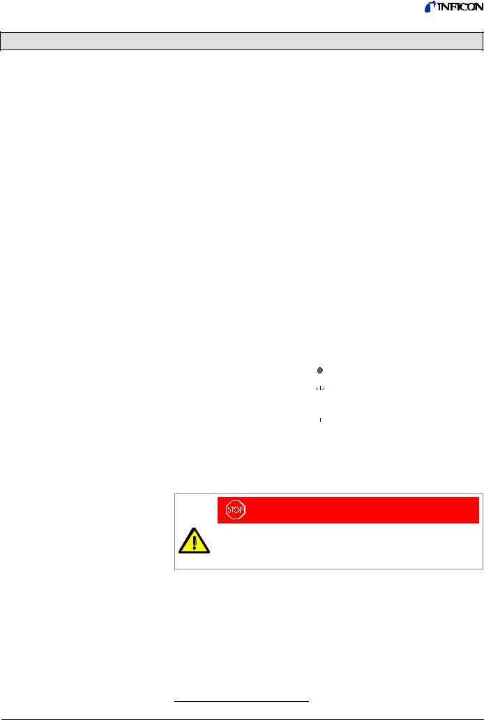
Dimensions [mm]
MPG400
60 |
75 |
55 |
|
92 |
|
28 |
ø 63.5 |
|
MPG401
105 32 15.5 55
|
|
|
|
|
|
60 |
75 |
||||
|
|
|
|
|
|
|
|
|
|
|
|
|
|
|
|
|
|
|
|
|
|
|
|
|
|
|
|
|
|
|
|
|
|
|
|
|
|
|
|
|
|
|
|
|
|
|
|
|
|
|
|
|
|
|
|
|
|
|
|
|
|
|
|
|
|
|
|
|
|
|
|
|
|
|
|
|
|
ø 63.5
18 |
24 |
18.5 |
DN 25 ISO-KF |
|
|
|
|
|
|
DN 40 ISO-KF |
|
|
|
DN 40 CF-F |
||||
Weight
351-010 |
≈700 g |
351-020 |
≈730 g |
351-011 |
≈720 g |
351-021 |
≈750 g |
351-012 |
≈980 g |
351-022 |
≈1010 g |
8 |
tina48e1-b (2008-10) MPG400-401.om |

3 Installation
3.1 Vacuum Connection
DANGER
DANGER: overpressure in the vacuum system >1 bar
Injury caused by released parts and harm caused by escaping process gases can result if clamps are opened while the vacuum system is pressurized.
Do not open any clamps while the vacuum system is pressurized. Use the type of clamps which are suited to overpressure.
DANGER
DANGER: overpressure in the vacuum system >2.5 bar
KF flange connections with elastomer seals (e.g. O-rings) cannot withstand such pressures. Process media can thus leak and possibly damage your health.
Use O-rings provided with an outer centering ring.
DANGER
DANGER: protective ground
Products that are not professionally connected to ground can be extremely hazardous in the event of a fault.
The gauge must be electrically connected to the grounded vacuum chamber. The connection must conform to the requirements of protective connection according to EN 61010:
•CF connections fulfill this requirement.
•For gauges with KF connections, use a conductive metallic clamping ring.
Caution
Caution: vacuum component
Dirt and damages impair the function of the vacuum component.
When handling vacuum components, take appropriate measures to ensure cleanliness and prevent damages.
Caution
Caution: dirt sensitive area
Touching the product or parts thereof with bare hands increases the desorption rate.
Always wear clean, lint-free gloves and use clean tools when working in this area.
WARNING
WARNING: electric arcing
Helium may cause electric arcing with detrimental effects on the electronics of the product.
Before performing any tightness tests put the product out of operation and remove the electronics unit.
tina48e1-b (2008-10) MPG400-401.om |
9 |
|
|
|
The gauge may be mounted in any orientation. To keep condensates |
|
|
|
|
|
|
|
|
|
|
|
and particles from getting into the measuring chamber preferably |
|
|
|
choose a horizontal to upright position and possibly use a seal with a |
|
|
|
centering ring and filter. |
|
|
|
If adjustment should be possible after the gauge has been installed, be |
|
|
|
|
|
|
|
|
|
|
|
sure to install it so that the <HV> and <ATM> trimmer potentiometers |
|
|
|
can be accessed with a screw driver (→ 16). |
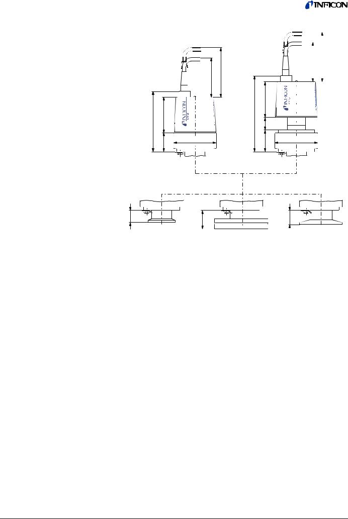
Procedure |
Remove the protective lid and install the product to the vacuum system. |
||
|
When making a CF flange connection, it may be advantageous to temporarily |
||
|
remove the magnet unit (→ 11). |
||
Seal with centering ring
or
|
Protective lid |
Clamp |
Seal with centering |
|
ring and filter |
Keep the protective lid.
10 |
tina48e1-b (2008-10) MPG400-401.om |
3.1.1Removing the Magnet Unit (Only for Gauges With CF Flanges)
Tools required
Procedure
•Allen wrench 1.5 mm
•Open-end wrench 7 mm
2
1
4
3
7
a)Unfasten the hexagon socket set screw (1) on the electronics unit (2).
b)Remove the electronics unit without twisting it.
c)Unfasten the hexagon head screw (3) on the magnet unit (4) and remove the magnet unit.

 The magnetic force and the tendency to tilt make it difficult to separate the magnet unit and the measuring chamber (7).
d)Make the flange connection between the gauge and the vacuum system.
e)Remount the magnet unit and lock it with the hexagon head screw (3).
f)Carefully mount the electronics unit (2). (Make sure the pin of the Pirani element is properly plugged into the corresponding hole of the electronics unit.)
g)Push the electronics unit up to the mechanical stop and lock it with the hexagon socket set screw (1).
tina48e1-b (2008-10) MPG400-401.om |
11 |
 Loading...