


 Loading...
O P E R A T I O N a n d S E R V I C E M A N U A L
MDC-360C
Film Deposition Controller
IPN 624800 Rev. F

O P E R A T I O N a n d S E R V I C E M A N U A L
MDC-360C
Film Deposition Controller
IPN 624800 Rev. F


 ®
®
www.inficon.com reachus@inficon.com
Due to our continuing program of product improvements, specifications are subject to change without notice.
©2007 INFICON

Trademarks
The trademarks of the products mentioned in this manual are held by the companies that produce them.
INFICON® is a trademark of INFICON Inc.
All other brand and product names are trademarks or registered trademarks of their respective companies.
Disclaimer
The information contained in this manual is believed to be accurate and reliable. However, INFICON assumes no responsibility for its use and shall not be liable for any special, incidental, or consequential damages related to the use of this product.
Disclosure
The disclosure of this information is to assist owners of INFICON equipment to properly operate and maintain their equipment, and does not constitute the release of rights thereof. Reproduction of this information and equipment described herein is prohibited without prior written consent from INFICON, Two Technology Place, East Syracuse, NY 13057-9714. Phone 315.434.1100. See www.inficon.com.
Copyright
©2004 All rights reserved.
Reproduction or adaptation of any part of this document without permission is unlawful.
January 2004, Revision A.
August 2004, Revision B.
June 2005, Revision C.
October 2005, Revision D.
October 2006, Revision E.
November 2007, Revision F
General Safety Warning
WARNING
All standard safety procedures associated with the safe handling of electrical equipment must be observed. Always disconnect power when working inside the controller. Only properly trained personnel should attempt to service the instrument.

DECLARATION
OF
CONFORMITY
This is to certify that this equipment, designed and manufactured by:
INFICON Inc.
Two Technology Place
East Syracuse, NY 13057
USA
meets the essential safety requirements of the European Union and is placed on the market accordingly. It has been constructed in accordance with good engineering practice in safety matters in force in the Community and does not endanger the safety of persons, domestic animals or property when properly installed and maintained and used in applications for which it was made.
Equipment Description: |
MDC-360C Thin Film Deposition Controllers, including the SO-100 |
|
Oscillator Package. |
Applicable Directives: |
73/23/EEC as amended by 93/68/EEC (LVD) |
|
89/336/EEC as amended by 93/68/EEC (EMC) |
|
2002/95/EC (RoHS) |
Applicable Standards: |
EN 61010-1:2001 (Safety) |
|
EN 61326-1:1997/A1:1998/A2:2001, Class A: Emissions per Table 3 |
|
Immunity per Table A.1 |
|
Due to the classification of this product it is currently exempt from the RoHS |
|
directive. |
CE Implementation Date: |
November 1, 2007 |
Authorized Representative: |
Duane H. Wright |
|
Quality Assurance Manager, ISS |
|
INFICON Inc. |
ANY QUESTIONS RELATIVE TO THIS DECLARATION OR TO THE SAFETY OF INFICON'S PRODUCTS SHOULD BE DIRECTED, IN WRITING, TO THE QUALITY ASSURANCE DEPARTMENT AT THE ABOVE ADDRESS.
10/01/07

Warranty
INFICON warrants the product to be free of functional defects in material and workmanship and that it will perform in accordance with its published specification for a period of (twenty-four) 24 months.
The foregoing warranty is subject to the condition that the product be properly operated in accordance with instructions provided by INFICON or has not been subjected to improper installation or abuse, misuse, negligence, accident, corrosion, or damage during shipment.
Purchaser's sole and exclusive remedy under the above warranty is limited to, at INFICON's option, repair or replacement of defective equipment or return to purchaser of the original purchase price. Transportation charges must be prepaid and upon examination by INFICON the equipment must be found not to comply with the above warranty. In the event that INFICON elects to refund the purchase price, the equipment shall be the property of INFICON.
This warranty is in lieu of all other warranties, expressed or implied and constitutes fulfillment of all of INFICON's liabilities to the purchaser. INFICON does not warrant that the product can be used for any particular purpose other than that covered by the applicable specifications. INFICON assumes no liability in any event, for consequential damages, for anticipated or lost profits, incidental damage of loss of time or other losses incurred by the purchaser or third party in connection with products covered by this warranty or otherwise.
www.inficon.com reachus@inficon.com
SAFETY PRECAUTION AND PREPARATION FOR USE
Input Power Requirements
The MDC-360C Deposition Controller can be set to operate one of the following line voltages: 100, 120, 200, or 240 VAC at line frequency of 50 or 60 Hz. Maximum power consumption is 25 watts. See Section 8.3.2 for instruction on selecting line voltage.
Power Entry Module
The AC (alternating current) power entry module, located in the rear panel of the MDC-360C, provides connection to the power source and a protective ground. It also holds the fuses and the voltage selection wheel.
Power Cord
WARNING: To avoid electrical shock, always connect the power cord to an AC outlet which has a proper protective ground.
The MDC-360C comes with a detachable, three-wire power cord for connection to a power source with protective ground.
The MDC-360C chassis is connected to the power ground to protect against electrical shock. Always connect to an AC outlet which has a properly connected protective ground. If necessary, or when in doubt, consult a certified electrician.
Grounding
A grounding lug is located on the rear panel, near the power entry module. Use heavy ground wire, wire braid, or copper strap of #12 AWG or larger to connect this grounding lug directly to a facility protective earth ground to provide additional protection against electrical shock. Refer to Section 8.2 and Figure 8-11 for details.
Line Fuses
There are two 5 x 20 mm fuses mounted inside the power entry module. They are accessible via the snap-in cover. Replace with the correct fuse rating: IEC T Type (Slow), 4/10 A, 250 VAC. Refer to Section 8.3.2 for instruction to replace the fuse.
Power Switch
WARNING: Do NOT use the power switch as a disconnecting device; disconnect the power cord from the power entry module to fully remove hazardous voltage from inside the MDC-360C.
The power switch is located on the front lower left of the MDC-360C. Toggle the switch to I to turn the controller on, or to O to turn it off. The MDC-360C is off when the LCD and all of the LEDs are off. However, turning the power switch off does not fully remove the AC power from inside the unit. Always disconnect the power cord from the power entry module to fully remove AC power from inside the unit.
iv
SAFETY TERMS AND SYMBOLS
Terms Used in This Manual
WARNING. Warning statements identify conditions or practices that could result in personnel injuries or loss of life.
CAUTION. Caution statements identify conditions or practices that could result in damage to the MDC-360C or other property.
NOTE. Note statements identify a sensitive or irreversible procedure. Proceed with caution.
Terms Used on the MDC-360C
DANGER indicates and injury hazard immediately accessible as you read the marking.
WARNING indicates an injury hazard not immediately accessible as you read the marking.
CAUTION indicates a hazard to the MDC-360C or other property.
Symbols Used on the Product and in the Manual
DANGER |
ATTENTION |
Protective Ground |
|
Hazardous Voltage |
Refer to Manual |
||
|
FUSE |
AC |
Refer to Manual for |
Alternating Current |
Instruction |
|
v
Table of Contents
SAFETY PRECAUTION AND PREPARATION FOR USE................................................... |
IV |
||
SAFETY TERMS AND SYMBOLS............................................................................................. |
V |
||
1. GENERAL DESCRIPTION............................................................................................. |
1-1 |
||
1.1 |
PURPOSE....................................................................................................................... |
1-1 |
|
1.2 |
FEATURES .................................................................................................................... |
1-1 |
|
1.2.1 |
|
MULTI-CRYSTAL AVERAGING ............................................................................... |
1-1 |
1.2.2 |
|
EXTENSIVE PROGRAM STORAGE ......................................................................... |
1-1 |
1.2.3 DYNAMIC MEASUREMENT UPDATE RATE .......................................................... |
1-1 |
||
1.2.4 SUPERIOR COLOR GRAPHICS DISPLAY .............................................................. |
1-1 |
||
1.2.5 |
|
PROGRAM SECURITY.............................................................................................. |
1-1 |
1.2.6 DESIGNED FOR UNATTENDED OPERATION ...................................................... |
1-1 |
||
1.2.7 |
|
FAIL SAFE ABORTS.................................................................................................. |
1-2 |
1.2.8 |
|
ABORT STATUS RETENTION .................................................................................. |
1-2 |
1.2.9 RUN COMPLETION ON CRYSTAL FAILURE ......................................................... |
1-2 |
||
1.2.10 |
POWERFUL SYSTEM INTERFACE..................................................................... |
1-2 |
|
1.2.11 |
POWER SUPPLY NOISE TOLERANCE............................................................... |
1-2 |
|
1.2.12 |
INTERNATIONAL STANDARD POWER CONNECTOR ..................................... |
1-2 |
|
1.2.13 |
FIELD UPGRADABLE ......................................................................................... |
1-2 |
|
1.3 |
SPECIFICATIONS......................................................................................................... |
1-3 |
|
1.3.1 |
|
MEASUREMENT ....................................................................................................... |
1-3 |
1.3.2 |
|
DISPLAY .................................................................................................................... |
1-3 |
1.3.3 |
|
COMMUNICATION................................................................................................... |
1-3 |
1.3.4 |
|
PROGRAM STORAGE CAPACITY ........................................................................... |
1-3 |
1.3.5 |
|
PROCESS PARAMETERS ......................................................................................... |
1-3 |
1.3.6 |
|
MATERIAL PARAMETERS ....................................................................................... |
1-4 |
1.3.7 |
|
INPUT/OUTPUT CAPABILITY ................................................................................. |
1-5 |
1.3.8 |
|
SENSOR PARAMETERS............................................................................................ |
1-5 |
1.3.9 |
|
SOURCE PARAMETERS........................................................................................... |
1-6 |
1.3.10 |
RECORDER PARAMETERS................................................................................. |
1-6 |
|
1.3.11 |
UTILITY SETUP PARAMETER ............................................................................ |
1-6 |
|
1.3.12 |
OTHER .................................................................................................................. |
1-6 |
|
1.4 |
ACCESSORIES.............................................................................................................. |
1-7 |
|
2. FRONT PANEL DISPLAYS AND CONTROLS ........................................................... |
2-1 |
||
2.1 |
OPERATING DISPLAYS .............................................................................................. |
2-1 |
|
2.1.1 |
|
RATE .......................................................................................................................... |
2-1 |
2.1.2 |
|
POWER ...................................................................................................................... |
2-1 |
2.1.3 |
|
THICKNESS............................................................................................................... |
2-1 |
2.1.4 |
|
LAYER NUMBER....................................................................................................... |
2-1 |
2.1.5 |
|
CRYSTAL HEALTH % ............................................................................................... |
2-1 |
2.1.6 |
|
TIME DISPLAY.......................................................................................................... |
2-2 |
2.2 |
PARAMETER/STATUS DISPLAYS ............................................................................ |
2-2 |
|
2.3 |
OPERATING CONTROLS ............................................................................................ |
2-2 |
|
2.3.1 |
|
MANUAL KEY ........................................................................................................... |
2-2 |
2.3.2 |
|
START KEY ................................................................................................................ |
2-3 |
2.3.3 |
|
ABORT KEY............................................................................................................... |
2-3 |
2.3.4 |
|
RESET KEY................................................................................................................ |
2-3 |
2.3.5 |
|
ZERO KEY ................................................................................................................. |
2-3 |
2.3.6 |
|
SHUTTER KEY .......................................................................................................... |
2-3 |
2.3.7 |
|
STATUS KEY.............................................................................................................. |
2-3 |
2.3.8 |
|
GRAPH KEY .............................................................................................................. |
2-3 |
2.3.9 |
|
ARROW KEYS............................................................................................................ |
2-4 |
vi
2.3.10 |
PROGRAM KEY.................................................................................................... |
2-4 |
|
2.3.11 |
ALPHANUMERIC KEYBOARD ........................................................................... |
2-5 |
|
3. BENCH CHECKOUT & INSPECTION......................................................................... |
3-1 |
||
3.1 |
INSPECTION................................................................................................................. |
3-1 |
|
3.2 |
INITIAL POWER UP ..................................................................................................... |
3-1 |
|
3.3 |
SAMPLE PROGRAM .................................................................................................... |
3-1 |
|
3.3.1 |
MATERIAL #1 PARAMETERS .................................................................................. |
3-2 |
|
3.3.2 |
MATERIAL #2 PARAMETERS .................................................................................. |
3-3 |
|
3.3.3 |
PROCESS PARAMETERS ......................................................................................... |
3-4 |
|
3.4 |
SIMULATE OPERATION............................................................................................. |
3-4 |
|
3.5 |
MANUAL OPERATION ............................................................................................... |
3-4 |
|
3.6 |
INSTALLING OPTION BOARDS ................................................................................ |
3-4 |
|
3.6.1 |
SOURCE-SENSOR BOARD ...................................................................................... |
3-5 |
|
3.6.2 |
DISCRETE I/O BOARD............................................................................................. |
3-5 |
|
3.6.3 |
IEEE-488 OPTION BOARD ...................................................................................... |
3-5 |
|
3.7 |
DIGITAL TO ANALOG CONVERTER (DAC) CHECKOUT...................................... |
3-5 |
|
4. PROGRAMMING AND CONTROLLER SETUP ........................................................ |
4-1 |
||
4.1 |
GENERAL...................................................................................................................... |
4-1 |
|
4.1.1 NAVIGATING THE MENU STRUCTURE ................................................................ |
4-1 |
||
4.1.2 |
ENTERING ALPHA CHARACTERS.......................................................................... |
4-1 |
|
4.1.3 |
ENTERING TIME PARAMETERS............................................................................. |
4-2 |
|
4.1.4 |
COPYING AND DELETING ..................................................................................... |
4-2 |
|
4.1.5 |
PASSWORD PROTECTION ...................................................................................... |
4-2 |
|
4.1.5.1 |
VIEW/RUN PROCESS PASSWORD ........................................................................... |
4-3 |
|
4.1.5.2 |
EDIT PROCESS PASSWORD ...................................................................................... |
4-3 |
|
4.1.5.3 |
EDIT MATERIAL PASSWORD................................................................................... |
4-3 |
|
4.1.6 ADJUSTING PARAMETER/STATUS DISPLAY CONTRAST ................................... |
4-3 |
||
4.2 |
GETTING STARTED .................................................................................................... |
4-3 |
|
4.2.1 |
UTILITY SETUP ........................................................................................................ |
4-4 |
|
4.2.2 |
DAC SETUP .............................................................................................................. |
4-4 |
|
4.2.3 |
SOURCE SETUP ....................................................................................................... |
4-4 |
|
4.2.4 |
SENSOR SETUP ........................................................................................................ |
4-7 |
|
4.2.4.1 |
EXAMPLE USING INFICON’S RSH-600 SIX CRYSTAL SENSOR HEAD ............ |
4-9 |
|
4.2.5 INPUT, OUTPUT AND ACTION SETUP.................................................................. |
4-9 |
||
4.2.6 |
DISPLAY SETUP...................................................................................................... |
4-10 |
|
4.2.7 |
MATERIAL SETUP................................................................................................... |
4-11 |
|
4.2.7.1 |
POWER RAMPS.......................................................................................................... |
4-11 |
|
4.2.7.2 |
AUTOMATIC CRYSTAL SWITCHING .................................................................... |
4-12 |
|
4.2.7.3 |
RATE ESTABLISH ..................................................................................................... |
4-12 |
|
4.2.7.4 |
RATE RAMPS ............................................................................................................. |
4-12 |
|
4.2.7.5 |
RATE SAMPLE MODE .............................................................................................. |
4-13 |
|
4.2.7.6 |
RATE DEVIATION ALARM...................................................................................... |
4-13 |
|
4.2.8 |
PROCESS SETUP..................................................................................................... |
4-13 |
|
4.2.9 STARTING A NEW PROCESS.................................................................................. |
4-13 |
||
4.2.10 |
RESUMING A PROCESS FROM ABORT OR HALT .......................................... |
4-14 |
|
4.3 |
DETAILED PROGRAMMING .................................................................................... |
4-14 |
|
4.3.1 |
VIEW/EDIT PROCESS ............................................................................................. |
4-14 |
|
4.3.1.1 |
DEFINE A PROCESS.................................................................................................. |
4-14 |
|
4.3.2 |
VIEW/EDIT MATERIAL ........................................................................................... |
4-16 |
|
4.3.2.1 |
DEFINE A MATERIAL............................................................................................... |
4-17 |
|
4.3.3 |
SYSTEM SETUP ....................................................................................................... |
4-25 |
|
4.3.3.1 |
EDIT DISPLAY SETUP .............................................................................................. |
4-25 |
|
4.3.3.2 |
PROGRAM INPUTS ................................................................................................... |
4-27 |
|
4.3.3.3 |
PROGRAM OUTPUTS................................................................................................ |
4-28 |
|
4.3.3.4 |
PROGRAM ACTIONS ................................................................................................ |
4-34 |
|
4.3.3.5 |
EDIT SENSOR SETUP................................................................................................ |
4-36 |
|
4.3.3.6 |
EDIT SOURCE SETUP ............................................................................................... |
4-39 |
|
4.3.3.7 |
EDIT DAC SETUP ...................................................................................................... |
4-42 |
|
vii
|
4.3.3.8 |
EDIT UTILITY SETUP ............................................................................................... |
4-42 |
|
5. |
OPERATING THE MDC-360C ....................................................................................... |
5-1 |
||
5.1 |
|
SIGN-ON SCREEN ........................................................................................................ |
5-1 |
|
5.2 |
|
STARTING A NEW PROCESS ..................................................................................... |
5-1 |
|
5.3 |
|
STARTING A NEW LAYER ......................................................................................... |
5-2 |
|
5.4 |
|
RESUMING AN ABORTED OR HALTED PROCESS................................................. |
5-2 |
|
5.5 |
|
GRAPH DISPLAYS ........................................................................................................ |
5-3 |
|
5.6 |
|
STATUS DISPLAYS...................................................................................................... |
5-4 |
|
5.7 |
|
VIEWING RESULTS..................................................................................................... |
5-5 |
|
5.8 |
|
MODES .......................................................................................................................... |
5-7 |
|
5.8.1 |
PROCESS READY...................................................................................................... |
5-7 |
||
5.8.2 |
ABORT ....................................................................................................................... |
5-7 |
||
5.8.3 |
HALT (SOFT ABORT) ............................................................................................... |
5-8 |
||
5.8.4 |
IN PROCESS.............................................................................................................. |
5-8 |
||
5.8.5 |
NOT SAMPLING........................................................................................................ |
5-8 |
||
5.8.6 |
PROCESS COMPLETE ............................................................................................. |
5-8 |
||
5.8.7 |
MANUAL.................................................................................................................... |
5-8 |
||
5.8.8 |
SIMULATE................................................................................................................. |
5-8 |
||
5.9 |
|
STATES.......................................................................................................................... |
5-8 |
|
5.10 TROUBLE, ERROR AND WARNING MESSAGES .................................................... |
5-8 |
|||
5.10.1 |
DESCRIPTION...................................................................................................... |
5-9 |
||
|
5.10.1.1 |
MIN RATE&MAX POWER........................................................................................ |
5-10 |
|
|
5.10.1.2 |
MAX RATE&MIN POWER........................................................................................ |
5-10 |
|
|
5.10.1.3 |
SYSTEM SETUP MEMORY CORRUPTED.............................................................. |
5-10 |
|
|
5.10.1.4 |
PROCESS MEMORY CORRUPTED ......................................................................... |
5-10 |
|
|
5.10.1.5 |
MATERIAL MEMORY CORRUPTED...................................................................... |
5-10 |
|
|
5.10.1.6 |
RATE EST. ERROR .................................................................................................... |
5-10 |
|
|
5.10.1.7 |
CRYSTAL FAILURE.................................................................................................. |
5-10 |
|
|
5.10.1.8 |
SOURCE FAULT ........................................................................................................ |
5-10 |
|
|
5.10.1.9 |
SENSOR FAULT......................................................................................................... |
5-11 |
|
|
5.10.1.10 |
NO SENSORS ENABLED .......................................................................................... |
5-11 |
|
|
5.10.1.11 |
TIME POWER ............................................................................................................. |
5-11 |
|
|
5.10.1.12 |
RATE DEV. ALARM.................................................................................................. |
5-11 |
|
|
5.10.1.13 |
ALARM ACTION ....................................................................................................... |
5-11 |
|
|
5.10.1.14 |
CRYSTAL MARGINAL ............................................................................................. |
5-11 |
|
|
5.10.1.15 |
RATE DEV. ALERT ................................................................................................... |
5-11 |
|
|
5.10.1.16 |
MAX POWER ALERT................................................................................................ |
5-11 |
|
|
5.10.1.17 |
MIN POWER ALERT ................................................................................................. |
5-11 |
|
|
5.10.1.18 |
ALERT ACTION......................................................................................................... |
5-11 |
|
|
5.10.1.19 |
XTAL FAIL SWITCH ................................................................................................. |
5-12 |
|
|
5.10.1.20 |
XTAL MRGN SWITCH .............................................................................................. |
5-12 |
|
|
5.10.1.21 |
RATE DEV. ATTEN ................................................................................................... |
5-12 |
|
|
5.10.1.22 |
MAXIMUM POWER .................................................................................................. |
5-12 |
|
|
5.10.1.23 |
MINIMUM POWER.................................................................................................... |
5-12 |
|
|
5.10.1.24 |
CHANGE POCKET..................................................................................................... |
5-12 |
|
|
5.10.1.25 |
CHANGE CRYSTAL... ............................................................................................... |
5-12 |
|
|
5.10.1.26 |
ATTENTION ACTION ............................................................................................... |
5-12 |
|
|
5.10.1.27 |
CALIBRATION DONE............................................................................................... |
5-12 |
|
6. TUNING THE MDC-360C CONTROL LOOP.............................................................. |
6-1 |
|||
6.1 |
|
CONTROL LOOP BASICS................................................................................................... |
6-1 |
|
6.2 |
|
CONTROL LOOPS APPLIED TO VACUUM DEPOSITION....................................................... |
6-2 |
|
6.3 |
|
ESTABLISHING MDC-360C CONTROL LOOP PARAMETERS ............................................. |
6-3 |
|
7. |
INPUT/OUTPUT CHARACTERISTICS........................................................................ |
7-1 |
||
7.1 |
|
SOURCE CONTROL VOLTAGE OUTPUT ................................................................. |
7-1 |
|
7.2 |
|
SENSOR INPUT............................................................................................................. |
7-1 |
|
7.3 |
|
DISCRETE OUTPUTS................................................................................................... |
7-1 |
|
viii
7.4 |
|
DISCRETE INPUTS ...................................................................................................... |
7-1 |
|
7.5 |
|
DIGITAL-TO-ANALOG CONVERTER OUTPUTS .................................................... |
7-2 |
|
7.6 |
|
DIGITAL-TO-ANALOG CONVERTER CONTROL INPUTS .................................... |
7-2 |
|
8. |
CONTROLLER INSTALLATION ................................................................................. |
8-1 |
||
8.1 |
|
MOUNTING .................................................................................................................. |
8-1 |
|
8.2 |
|
PROPER GROUNDING ................................................................................................ |
8-1 |
|
8.3 |
|
EXTERNAL CONNECTIONS ...................................................................................... |
8-1 |
|
8.3.1 |
|
POWER...................................................................................................................... |
8-1 |
|
8.3.2 LINE VOLTAGE SELECTION AND FUSE REPLACEMENT .................................. |
8-2 |
|||
8.3.3 |
|
GROUND LUG.......................................................................................................... |
8-2 |
|
8.3.4 |
|
REMOTE POWER HANDSET................................................................................... |
8-3 |
|
8.3.5 |
|
SOURCE-SENSOR .................................................................................................... |
8-3 |
|
8.3.6 |
|
RS-232 COMMUNICATION...................................................................................... |
8-3 |
|
8.3.7 |
|
DISCRETE INPUT/OUTPUT .................................................................................... |
8-3 |
|
8.3.8 |
|
DIGITAL-TO-ANALOG CONVERTER (DAC).......................................................... |
8-4 |
|
8.4 |
|
POWER SWITCH ............................................................................................................... |
8-4 |
|
8.5 |
|
CONTROLLER COVER REMOVAL ........................................................................... |
8-4 |
|
9. |
SYSTEM INSTALLATION ............................................................................................. |
9-1 |
||
9.1 |
|
SENSOR HEAD DESCRIPTION .................................................................................. |
9-1 |
|
9.2 |
|
SENSOR HEAD INSTALLATION ............................................................................... |
9-1 |
|
9.3 |
|
SENSOR OSCILLATOR ............................................................................................... |
9-2 |
|
9.3.1 |
|
INSTALLATION......................................................................................................... |
9-2 |
|
9.4 |
|
INSTRUMENTATION FEEDTHROUGH .................................................................... |
9-2 |
|
9.5 |
|
SENSOR CRYSTAL REPLACEMENT ........................................................................ |
9-2 |
|
9.5.1 CRYSTAL CARE AND HANDLING........................................................................... |
9-3 |
|||
9.5.2 |
|
CRYSTAL REPLACEMENT PROCEDURE .............................................................. |
9-3 |
|
9.6 |
|
TYPICAL SYSTEM INSTALLATION ......................................................................... |
9-5 |
|
10. |
|
THEORY OF OPERATION ...................................................................................... |
10-1 |
|
10.1 |
|
BASIC MEASUREMENT ............................................................................................ |
10-1 |
|
10.2 |
|
FILM THICKNESS CALCULATION.......................................................................... |
10-1 |
|
10.3 |
|
CRYSTAL HEALTH CALCULATION ....................................................................... |
10-3 |
|
10.4 |
|
RATE CALCULATION................................................................................................ |
10-3 |
|
10.5 |
|
MULTI-SENSOR AVERAGING ........................................................................................... |
10-4 |
|
10.6 |
|
EMPIRICAL CALIBRATION ...................................................................................... |
10-5 |
|
10.6.1 |
FILM DENSITY.................................................................................................... |
10-5 |
||
10.6.2 |
TOOLING FACTOR............................................................................................. |
10-5 |
||
10.6.3 |
ACOUSTIC IMPEDANCE ................................................................................... |
10-6 |
||
11. |
|
COMPUTER INTERFACE........................................................................................ |
11-1 |
|
11.1 |
|
GENERAL..................................................................................................................... |
11-1 |
|
11.2 |
|
RS-232 SERIAL INTERFACE...................................................................................... |
11-1 |
|
11.3 |
|
RS-485 SERIAL INTERFACE...................................................................................... |
11-1 |
|
11.4 |
|
IEEE-488 PARALLEL INTERFACE............................................................................ |
11-2 |
|
11.5 |
|
PROTOCOL .................................................................................................................. |
11-2 |
|
11.6 |
|
DATA TYPES ............................................................................................................... |
11-3 |
|
11.7 |
|
MESSAGE RECEIVED STATUS ................................................................................ |
11-3 |
|
11.8 |
|
INSTRUCTION SUMMARY ....................................................................................... |
11-4 |
|
11.9 |
|
INSTRUCTION DESCRIPTIONS................................................................................ |
11-5 |
|
12. |
|
REPAIR AND MAINTENANCE............................................................................... |
12-1 |
|
12.1 |
|
HANDLING PRECAUTIONS ...................................................................................... |
12-1 |
|
12.2 |
|
MAINTENANCE PHILOSOPHY................................................................................. |
12-1 |
|
12.3 |
|
TROUBLE SHOOTING AIDS...................................................................................... |
12-2 |
|
12.4 |
|
RETURNING THE MDC-360C TO THE FACTORY .................................................. |
12-3 |
|
ix
13. |
APPENDIX A – MATING CABLE COLOR CODES |
............................................ 13-1 |
14. |
APPENDIX B – PARAMETER TEMPLATES ....................................................... |
14-1 |
14.1 |
MATERIAL.................................................................................................................. |
14-2 |
14.2 |
PROCESS ..................................................................................................................... |
14-4 |
14.3 |
DISPLAY SETUP......................................................................................................... |
14-5 |
14.4 |
INPUTS ........................................................................................................................ |
14-6 |
14.5 |
OUTPUTS..................................................................................................................... |
14-7 |
14.6 |
ACTIONS ..................................................................................................................... |
14-8 |
14.7 |
SENSOR SETUP .......................................................................................................... |
14-9 |
14.8 |
SOURCE SETUP.......................................................................................................... |
14-9 |
14.9 |
DAC SETUP ............................................................................................................... |
14-10 |
14.10 |
UTILITY SETUP........................................................................................................ |
14-10 |
15. |
INDEX.............................................................................................................................. |
11 |
16. |
MENU MAPS.............................................................................................................. |
16-1 |
x
Table of Figures
FIGURE 2-1 OPERATING DISPLAY........................ |
ERROR! BOOKMARK NOT DEFINED. |
|
FIGURE 2-2 PARAMETER/STATUS DISPLAY...................................................................... |
|
2-2 |
FIGURE 2-3 PROGRAMMING SECTION................................................................................. |
|
2-4 |
FIGURE 2-4 ARROW KEYS....................................................................................................... |
|
2-4 |
FIGURE 2-5 ALPHANUMERIC KEYBOARD .......................................................................... |
|
2-5 |
FIGURE 3-1 REMOTE POWER HANDSET ............................................................................. |
|
3-7 |
FIGURE 4-1 THE MAIN MENU................................................................................................ |
|
4-1 |
FIGURE 4-2 SELECT PROCESS SCREEN.............................................................................. |
|
4-14 |
FIGURE 4-3 DEFINE PROCESS SCREEN .............................................................................. |
|
4-14 |
FIGURE 4-4 SELECT LAYER MATERIAL SCREEN ............................................................. |
4-16 |
|
FIGURE 4-5 SELECT MATERIAL SCREEN............................................................................ |
|
4-16 |
FIGURE 4-6 DEFINE MATERIAL SCREEN............................................................................ |
|
4-17 |
FIGURE 4-7 SYSTEM SETUP MENU SCREEN ..................................................................... |
|
4-25 |
FIGURE 4-8 DISPLAY SETUP SCREEN................................................................................. |
|
4-25 |
FIGURE 4-9 PROGRAM INPUT SCREEN ............................................................................... |
|
4-28 |
FIGURE 4-10 SELECT OUTPUT SCREEN ............................................................................. |
|
4-29 |
FIGURE 4-11 PROGRAM OUTPUT SCREEN ........................................................................ |
|
4-29 |
FIGURE 4-12 OUTPUT CONDITIONS SELECTION SCREEN .............................................. |
4-30 |
|
FIGURE 4-13 OUTPUT CONDITIONS SELECTION - SUB MENU....................................... |
4-31 |
|
FIGURE 4-14 ACTION SELECTION SCREEN........................................................................ |
|
4-34 |
FIGURE 4-15 PROGRAM ACTION SCREEN.......................................................................... |
|
4-34 |
FIGURE 4-16 SELECT DEFINED ACTION SCREEN ............................................................. |
4-35 |
|
FIGURE 4-17 SENSOR SETUP SCREEN ................................................................................ |
|
4-36 |
FIGURE 4-18 SOURCE SETUP SCREEN................................................................................ |
|
4-39 |
FIGURE 4-19 DAC SETUP SCREEN ....................................................................................... |
|
4-42 |
FIGURE 4-20 UTILITY SETUP SCREEN................................................................................ |
|
4-43 |
FIGURE 5-1 SIGN-ON SCREEN ............................................................................................... |
|
5-1 |
FIGURE 5-2 RUN PROCESS SELECTION SCREEN .............................................................. |
5-2 |
|
FIGURE 5-3 RATE VS. TIME GRAPH ..................................................................................... |
|
5-3 |
FIGURE 5-4 RATE DEVIATION VS. TIME GRAPH .............................................................. |
5-3 |
|
FIGURE 5-5 THICKNESS VS. TIME GRAPH.......................................................................... |
|
5-3 |
FIGURE 5-6 POWER VS. TIME GRAPH.................................................................................. |
|
5-4 |
FIGURE 5-7 SOURCE/SENSOR STATUS SCREEN................................................................ |
5-4 |
|
FIGURE 5-8 I/O STATUS SCREEN .......................................................................................... |
|
5-5 |
FIGURE 5-9 VIEW RESULTS SCREEN ................................................................................... |
|
5-6 |
FIGURE 5-10 RATE VS. TIME PROCESS LOG GRAPH........................................................ |
5-7 |
|
FIGURE 5-11 TYPICAL PROCESS PROFILE......................................................................... |
|
5-13 |
FIGURE 7-1 PASSIVE INPUT BUFFER CIRCUIT .................................................................. |
|
7-3 |
FIGURE 7-2 ACTIVE INPUT BUFFER CIRCUIT..................................................................... |
|
7-4 |
FIGURE 7-3 DAC OUTPUT CIRCUIT...................................................................................... |
|
7-5 |
FIGURE 7-4 SENSOR INPUT BUFFER CIRCUIT .................................................................. |
|
7-6 |
FIGURE 7-5 SOURCE OUTPUT DRIVER CIRCUIT............................................................... |
7-7 |
|
FIGURE 8-1 POWER ENTRY MODULE................................................................................... |
|
8-2 |
FIGURE 8-2 MDC-360C FRONT PANEL ................................................................................. |
|
8-6 |
FIGURE 8-3 MDC-360C REAR PANEL ................................................................................... |
|
8-7 |
FIGURE 8-4 DAC SOCKET CONNECTOR PIN OUT ............................................................. |
8-8 |
|
FIGURE 8-5 SOURCE SOCKET CONNECTOR PIN OUT...................................................... |
8-8 |
|
FIGURE 8-6 D9S DTE REAR-PANEL RS-232 SOCKET CONNECTOR................................ |
8-9 |
|
FIGURE 8-7 D37P DISCRETE I/O PLUG CONNECTOR........................................................ |
8-10 |
|
FIGURE 8-8 RJ11 FRONT PANEL RS-232 CONNECTOR .................................................... |
8-11 |
|
FIGURE 8-9 FRONT PANEL MANUAL POWER CONNECTOR ......................................... |
8-11 |
|
FIGURE 8-10 MDC-360C TOP VIEW (COVER REMOVED) ................................................ |
8-12 |
|
FIGURE 8-11 RECOMMENDED GROUNDING METHOD.................................................... |
8-13 |
|
FIGURE 9-1 REMOVING THE CRYSTAL RETAINER ........................................................... |
9-4 |
|
FIGURE 9-2 INSTALLING THE SENSOR CRYSTAL ............................................................. |
9-4 |
|
xi
FIGURE 9-3 SENSOR OSCILLATOR SCHEMATIC ............................................................... |
9-6 |
|
FIGURE 9-4 |
SENSOR OSCILLATOR OUTLINE..................................................................... |
9-7 |
FIGURE 9-5 |
IF-111 INSTRUMENTATION FEEDTHROUGH OUTLINE.............................. |
9-8 |
FIGURE 9-6 |
SH-102 SENSOR HEAD OUTLINE ..................................................................... |
9-9 |
FIGURE 9-7 |
TYPICAL SYSTEM INSTALLATION............................................................... |
9-10 |
FIGURE 13-1 PLUG PIN OUT - SOURCE CABLE CONNECTOR........................................ |
13-1 |
|
FIGURE 13-2 PLUG PIN OUT - DAC CABLE CONNECTOR ............................................... |
13-2 |
|
FIGURE 16-1 MAP OF STATUS AND GRAPH SCREENS.................................................... |
16-1 |
|
FIGURE 16-2 MAP OF PROGRAMMING MENU SCREENS ................................................ |
16-2 |
|
xii
List of Tables
TABLE 4-1TABLE OF INPUT STATES FOR BCD FEEDBACK TYPE................................. |
4-38 |
|
TABLE 4-2 TABLE OF INPUT STATES FOR BCD FEEDBACK TYPE................................ |
4-41 |
|
TABLE 5-1 TROUBLE CONDITIONS AND WARNINGS...................................................... |
5-9 |
|
TABLE 6-1 DEFAULT AND RANGE FOR PID PARAMETERS............................................. |
6-3 |
|
TABLE 6-2 SUGGESTED PID STARTING VALUES FOR DIFFERENT SOURCES............. |
6-3 |
|
TABLE 8-1 DAC SYSTEM INTERFACE CONNECTOR PIN ASSIGNMENTS .................... |
8-8 |
|
TABLE 8-2 |
SOURCE CONTROL SYSTEM INTERFACE CONNECTOR PIN |
|
ASSIGNMENTS ................................................................................................................. |
8-8 |
|
TABLE 8-3 |
D9 REAR PANEL RS-232/RS-485 CONNECTOR PIN ASSIGNMENTS ........... |
8-9 |
TABLE 8-4 |
DISCRETE I/O SYSTEM INTERFACE CONNECTOR PIN ASSIGNMENTS .. |
8-10 |
TABLE 8-5 |
RJ11 FRONT PANEL RS-232 CONNECTOR PIN ASSIGNMENTS.................. |
8-11 |
TABLE 8-6 FRONT PANEL MANUAL POWER CONNECTOR PIN ASSIGNMENTS....... |
8-11 |
|
TABLE 10-1 MATERIAL DENSITY AND ACOUSTIC IMPEDANCE VALUE.................... |
10-7 |
|
TABLE 13-1 SOURCE CONTROL CABLE COLOR CODE - (4 PIN MINI DIN) ............... |
13-1 |
|
TABLE 13-2 DAC CABLE COLOR CODE - (7 PIN MINI DIN) ......................................... |
13-2 |
|
xiii

MDC-360C DEPOSITION CONTROLLER
1.GENERAL DESCRIPTION
1.1PURPOSE
The MDC-360C is a full-featured deposition controller which can provide automatic control of single or multi-layer film deposition in either a production or development environment. The MDC-360C will improved predictability and repeatability of deposited film characteristics through dependable digital control and multi-sensor averaging.
The MDC-360C makes programming and operation easy with large LED displays for important run-time values, a graphic LCD display for graphs of rate, rate deviation, thickness and deposit power, an easy to use menu-driven user interface providing unparalleled access to plain English programming of processes, materials, inputs and outputs.
1.2FEATURES
The MDC-360C incorporates numerous features which are economically justifiable as a result of rapid advances in semiconductor technology and the advent of low cost microprocessors.
1.2.1MULTI-CRYSTAL AVERAGING
The MDC-360C provides greater accuracy in thin film deposition by averaging up to six sensors distributed throughout the chamber to account for changes in vapor distribution during deposition.
1.2.2EXTENSIVE PROGRAM STORAGE
The MDC-360C is capable of storing up to 99 processes, 999 layer definitions and 32 complete material definitions. Once a program is entered it will be maintained in memory for a minimum of 5 years without external power.
1.2.3DYNAMIC MEASUREMENT UPDATE RATE
Measurement is dynamically adjusted from 0.5 to 10 Hz for optimum resolution and control.
1.2.4SUPERIOR COLOR GRAPHICS DISPLAY
The MDC-360C features a 240x64 pixel color LCD graphics display allowing real time graphing of important process information such as rate, rate deviation, thickness and power.
1.2.5PROGRAM SECURITY
To assure the integrity of stored programs, the MDC-360C incorporates edit passwords to guard against unauthorized program changes.
1.2.6DESIGNED FOR UNATTENDED OPERATION
The MDC-360C has been designed for truly automatic operation and toward this end incorporates extensive internal monitoring and overriding abort circuitry to
GENERAL DESCRIPTION 1-1

MDC-360C DEPOSITION CONTROLLER
minimize the possibility of damage in the event of a failure or other problem in the total deposition system. In addition there are attention, alert and alarm signals with adjustable volume for trouble and routine operator call.
1.2.7FAIL SAFE ABORTS
In the event of an MDC-360C failure, as evidenced by unsatisfactory internal checks, the MDC-360C will abort the process and shut off all outputs. In addition to the internal checks, the MDC-360C also provides user enabled aborts on excessive rate control error or crystal failure.
1.2.8ABORT STATUS RETENTION
In the event that the MDC-360C does abort during the deposition process, pertinent information is stored at the time of abort. More importantly, the process can be easily resumed once the problem is corrected without re-programming.
1.2.9RUN COMPLETION ON CRYSTAL FAILURE
The extensive monitoring and abort functions are designed to protect the system and/or process from serious and hopefully infrequent malfunctions of the deposition system. A condition which need not cause an abort is the condition of crystal failure. The MDC-360C can be set to abort upon crystal failure or run to completion using a backup crystal or time/power method.
1.2.10 POWERFUL SYSTEM INTERFACE
Fully programmable discrete inputs and outputs permit the MDC-360C to be easily interfaced into deposition systems controlling the most complex processes. Also, source control outputs are fully isolated avoiding ground loop problems. The MDC-360C also supports input from an optical monitor for optical termination of film thickness.
1.2.11 POWER SUPPLY NOISE TOLERANCE
Integral RFI filter and large energy storage capacitors will tolerate high levels of power supply noise and power interruptions of 700 ms or less without effect.
1.2.12 INTERNATIONAL STANDARD POWER CONNECTOR
The power connector is internationally approved and meets IEC (International Electrotechnical Commission) standards. It allows selection of input power voltages ranging from 100 to 240 volts at a frequency of 50 or 60 Hz and includes an integral RFI filter.
1.2.13 FIELD UPGRADABLE
Plug-in interface boards and option boards allow the basic unit to be upgraded in the field to the maximum system level.
1-2 GENERAL DESCRIPTION
MDC-360C DEPOSITION CONTROLLER
1.3SPECIFICATIONS
1.3.1 |
MEASUREMENT |
|
Frequency Resolution |
0.03 Hz @ 6.0 MHz |
|
Mass Resolution |
0.375 ng/cm2 |
|
Thickness Accuracy |
0.5% + 1 count |
|
Measurement Update Rate |
Dynamically adjusted, 0.5 to 10 Hz |
|
Display Update Rate |
10 Hz |
|
Sensor Crystal Frequency |
2.5, 3, 5, 6, 9, 10 MHz |
|
1.3.2 |
DISPLAY |
|
|
|
|
Thickness Display |
Autoranging: 0.000 to 999.9 KÅ |
|
Rate Display |
Autoranging: 0.0 to 999 Å/sec |
|
Power Display |
0.0 to 99.9% |
|
Time Display |
0 to 9:59:59 H:MM:SS |
|
Crystal Health % |
0 to 99% |
|
Layer Number |
1 to 999 |
|
Graphics Display |
240X64 LCD with CCFL |
|
|
|
backlighting |
1.3.3 |
COMMUNICATION |
|
|
|
|
|
|
RS-232 serial port standard |
|
|
RS-485 serial port optional |
|
|
IEEE-488 bus interface optional |
1.3.4PROGRAM STORAGE CAPACITY
Process |
99, user definable |
Layer |
999, user definable |
Material |
32, user definable |
1.3.5PROCESS PARAMETERS
Process Name |
12 character string |
Edit password |
4 character string |
Run/View password |
4 character string |
Layer# 1 to 999 |
Material name, Thickness |
GENERAL DESCRIPTION 1-3

MDC-360C DEPOSITION CONTROLLER
1.3.6MATERIAL PARAMETERS
Material Name |
10 character string |
Source # |
1 to 6 |
Pocket # |
1 to 16 |
Material Density |
0.80 to 99.9 gm/cm3 |
Acoustic Impedance |
0.50 to 59.9 gm/cm2 sec |
Tooling Factor |
10.0 to 499.9% |
Proportional Gain |
0.00 to 9999 |
Integral Time Constant |
0 to 99.9 sec |
Derivative Time Constant |
0 to 99.9 sec |
Rise to Soak Time |
0 to 9:59:59 H:MM:SS |
Soak Power |
0 to 99% |
Soak Time |
0 to 9:59:59 |
Rise to Predeposit Time |
0 to 9:59:59 |
Predeposit Power |
0 to 99.9% |
Predeposit Time |
0 to 9:59:59 |
Rate Establish Time |
0 to 60 sec |
Rate Establish Error |
0 to 99.9% |
Deposition Rate (1 to 5) |
00.0 to 999.9 Å/sec |
Rate Start Thickness (1 to 4) |
0 to 100% |
Rate Stop Thickness (1 to 4) |
0 to 100% |
Time Setpoint |
0 to 9:59:59 |
Ramp to Feed Time |
0 to 9:59:59 |
Feed Power |
0 to 99.9% |
Feed Time |
0 to 9:59:59 |
Ramp to Idle Time |
0 to 9:59:59 |
Idle Power |
0 to 99.9% |
Maximum Power |
0 to 99.9% |
Power Alarm Delay |
0 to 99 sec |
Minimum Power |
0 to 99.9% |
Rate Deviation Attention |
0 to 99.9% |
Rate Deviation Alarm |
0 to 99.9% |
Rate Deviation Abort |
0 to 99.9% |
Sample Dwell % |
0 to 100.0% |
Sample Period |
0:01:00 to 9:59:59 |
Sensor (1 to 6) Fail |
NotUsed, Disable, HaltLast, Halt, |
|
TimePower, Switch |
Sensor (1 to 6) Tooling |
10.0 to 499.9% |
Sensor (1 to 6) Weight |
10.0 to 499.9% |
Sensor (1 to 6) Crystal # |
1 to 8 |
Sensor (1 to 6) Backup Sensor # |
1 to 6 |
Sensor (1 to 6) Backup Crystal # |
1 to 8 |
Material Password |
4 character string |
1-4 GENERAL DESCRIPTION

MDC-360C DEPOSITION CONTROLLER
The MDC-360C also has a built in material library that contains many common material names along with their density and acoustic impedance values.
1.3.7INPUT/OUTPUT CAPABILITY
Sensor Inputs |
2 Standard, up to 6 optional, BNC |
|
inputs |
Source Outputs |
2 Standard, up to 6 optional, fully |
|
isolated, 2.5, 5, 10 volts @ 20 ma. |
|
0.002% resolution |
Discrete Inputs |
8 Standard, up to 16 optional fully |
|
programmable inputs. |
|
The Passive I/O card (PN#179216) |
|
has TTL level inputs activated by a |
|
short across the input pins. |
|
The Active I/O card (PN#179239) has |
|
inputs activated by 12 to 120 volt |
|
AC/DC across the input pins. |
Discrete Outputs |
8 standard, up to 16 optional fully |
|
programmable, SPST relay, 120VA, |
|
2A max. |
Abort Output |
1 standard and 1 optional SPST |
|
Relay, 120VA, 2A max. |
Remote Power Handset |
Front panel, RJH jack |
RS-232 Communication |
Rear panel, 9 pin, Full duplex, DTE |
|
Front panel, RJ11 jack, Full duplex |
DAC Recorder Outputs |
Two 0 to 5 volts, 0.02% resolution |
1.3.8SENSOR PARAMETERS
Number of Crystals |
1 to 8 |
Shutter Relay Type |
Normally open, normally closed, dual, |
|
or none. |
Position Control |
Manual, direct, BCD, or individual. |
Position Drive |
Up, down, Fast, inline, single step, or |
|
double step. |
Feedback Type |
Individual, BCD, single home, in |
|
position, or no feedback. |
Rotator Delay |
0 to 99 sec |
GENERAL DESCRIPTION 1-5

MDC-360C DEPOSITION CONTROLLER
1.3.9 |
SOURCE PARAMETERS |
|
Number of Pockets |
1 to 16 |
|
Shutter Relay Type |
Normally open, normally closed, or |
|
|
|
none. |
Shutter Delay |
0.0 to 9.9 sec |
|
Position Control |
Manual, direct, BCD, or individual. |
|
Position Drive |
Up, down, Fast, inline, single step, or |
|
|
|
double step. |
Feedback Type |
Individual, BCD, single home, in |
|
|
|
position, or no feedback. |
Rotator Delay |
0 to 99 sec |
|
Source Voltage Range |
2.5, 5, 10 volts |
|
1.3.10 |
RECORDER PARAMETERS |
|
|
|
|
Recorder #1/#2 Output |
Rate, rate dev., power or thickness |
|
Recorder #1/#2 Scale |
Full scale %, 2/3 digit |
|
1.3.11 |
UTILITY SETUP PARAMETER |
|
|
|
|
Crystal Frequency |
2.5, 3, 5, 6, 9, 10 MHz |
|
Simulate Mode |
On/Off |
|
Interface Address |
1 to 32 |
|
Attention Volume |
0 to 10 |
|
Alert Volume |
0 to 10 |
|
Alarm Volume |
0 to 10 |
|
Data Points/Minute |
30,60,120,300,600 PPM |
|
Time |
|
0 to 23:59 |
Date |
|
MM/DD/YY |
1.3.12 |
OTHER |
|
|
|
|
Input Power Requirements |
100, 120, 200, 240 VAC; 50/60 Hz; |
|
|
|
25 watts |
Operating Temperature Range |
0 to 50 C |
|
Physical Weight |
10 LB |
|
Physical Size |
19” rackmount case |
|
|
|
3 1/2” high x 9 3/8” deep |
1-6 GENERAL DESCRIPTION

MDC-360C DEPOSITION CONTROLLER
1.4ACCESSORIES
The table below lists the most popular options and accessories. Refer to INFICON Price List for more accessories and other products.
Part Number |
Description |
179215 |
Dual Source/Sensor Board |
179216 |
Passive I/O Board |
179217 |
IEEE-488 Communication Board |
179218 |
Internal Storage Data/Time Clock |
179219 |
RS-232 to RS-485 conversion |
179220 |
Remote Power Handset |
179239 |
Active I/O Board |
123200-5 |
SH-102 Sensor Head, cables, and |
|
carousel of 10 each 6MHz Gold SC- |
|
101 sensor crystals |
124201-4 |
SO-100 Oscillator with 6" and 10' |
|
BNC Cables. |
130200-2 |
IF-111 Instrument Feedthrough, 1" O- |
|
Ring with 1 electrical connector and |
|
dual 3/16" water tubes. |
130204-2 |
IF-276 Instrumentation Feedthrough, |
|
2 3/4" Conflat® Flange seal with 1 |
|
electrical connector and dual 3/16" |
|
water tubes. |
150902 |
SF-120 Combination Sensor Head, |
|
Feedthrough, Cables, Crystals and |
|
Oscillator. |
123204-1 |
Internal Coax Cable 30". |
123204-2 |
Internal Coax Cable 60". |
124202-1 |
BNC Cable Assembly 10'. |
124202-2 |
BNC Cable Assembly 20' |
124204 |
BNC Cable Assembly 6". |
103220 |
SC-101 Carousel of 10 each 6MHz |
|
gold sensor crystals. |
103221 |
SC-102 Carousel of 10 each 6MHz |
|
silver sensor crystals. |
GENERAL DESCRIPTION 1-7
MDC-360C DEPOSITION CONTROLLER
2.FRONT PANEL DISPLAYS AND CONTROLS
The front panel is divided into two sections, the operating section and the programming section. The left half of the panel is devoted to the operating displays and controls. The right half is used for programming, viewing stored processes, and displaying the status of the selected process.
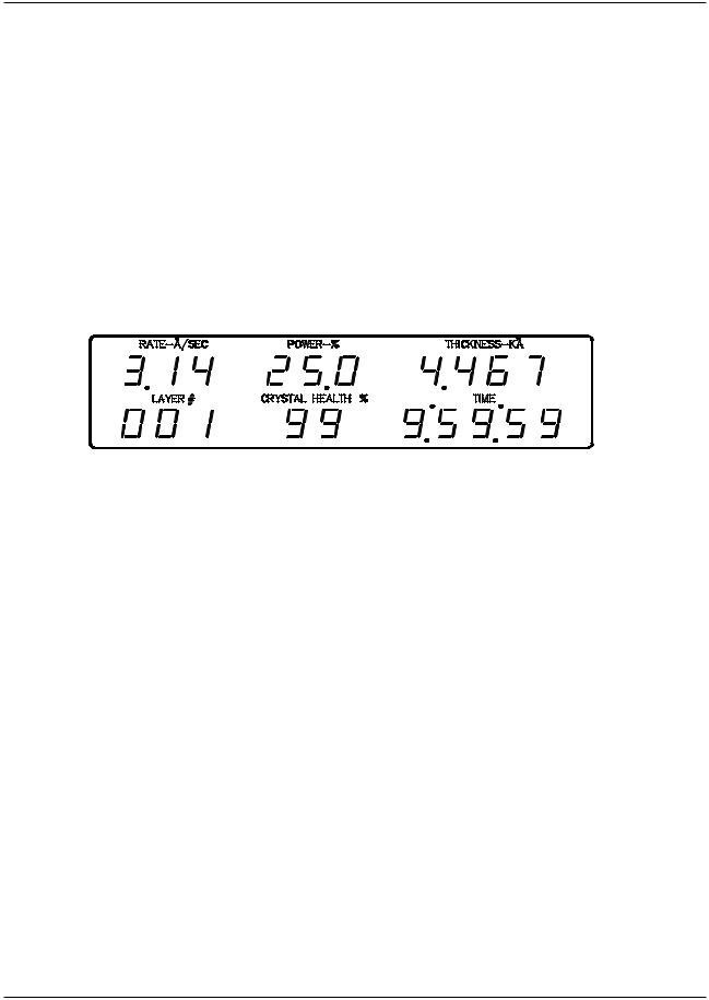
2.1OPERATING DISPLAYS
All of the operating displays are updated ten times per second unless the controller is in the Abort mode. When in the Abort mode, the values of the operating displays are held constant so the operator will know the values at the time of the Abort. The controller will also flash the operating displays while in Abort to alert the operator.
Figure 2-1 Operating Display
2.1.1RATE
A three digit display with a floating decimal point is used to display deposition rate in angstroms per second at a resolution of 0.1 Å/sec from 0 to 99.9 Å/sec, and a resolution of 1.0 Å/sec for rates from 100 to 999 Å/sec.
2.1.2POWER
A three digit display with a fixed decimal point displays percent of maximum power with a resolution of 0.1% from 0 to 99.9%. This corresponds to the control voltage range of 0 to 9.99 volts.
2.1.3THICKNESS
Four digits with an autoranging decimal point display measured thickness in KÅ with a resolution of 1 Å from 0 to 9.999 KÅ, a resolution of 10 Å from 10.00 KÅ to 99.99 KÅ and a resolution of 100 Å from 100.0 KÅ to 999.9 KÅ.
2.1.4LAYER NUMBER
Three digits display the layer number of the current process.
2.1.5CRYSTAL HEALTH %
A two-digit display is used to show the health percentage of the active sensor/crystal. If multiple sensors/crystals are active then the crystal with the lowest health will be displayed. A fresh crystal starts out with a health of 99%.
FRONT PANEL DISPLAYS AND CONTROLS 2-1
MDC-360C DEPOSITION CONTROLLER
2.1.6TIME DISPLAY
Time is displayed in hours, minutes and seconds. This display can be configured to show the estimated time to go for the state or layer or the elapsed process, layer or state times.
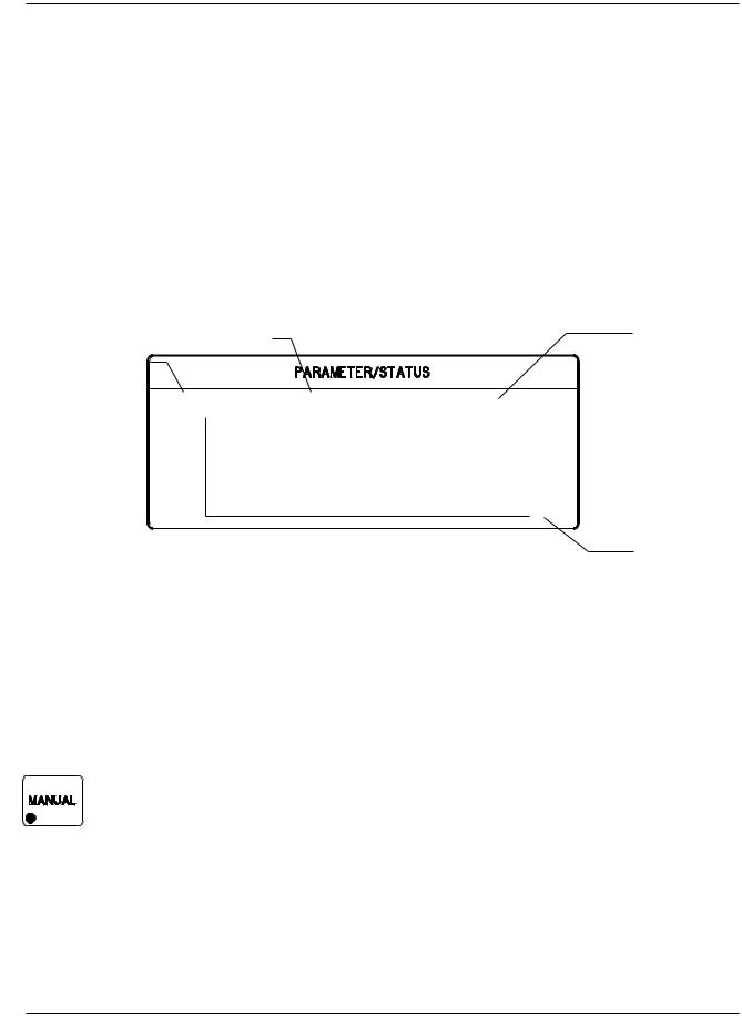
2.2PARAMETER/STATUS DISPLAYS
A graphics display labeled Parameter/Status is used for process programming and controller setup as well as displaying run-time status and data graphing. The operator can switch between programming screens and status screens by pressing the Program and Status keys on the front panel. Upon power up, the Parameter/Status display automatically reverts to the last viewed status screen. Detail descriptions of the different programming and status screens can be found in Section 4 and 5.
|
Displays the current |
|
Displays the |
|
|
controller modes, |
|
Displays the current |
material name. |
|
|
|
states or troubles. |
||
|
|
||
process name. |
|
|
|
|
Sample |
Cr |
Process Ready |
|
10 |
|
Rate |
0 |
1 |
|
|
Figure 2-2 Parameter/Status Display
Displays the time axis scale factor
2.3OPERATING CONTROLS
Normal operation of the MDC-360C is controlled by eight operating keys, Manual, Start, Abort, Reset, Zero, Shutter, Status, and Graph. Except for the Zero, Status, and Graph keys, each of the other keys is equipped with an LED to indicate the controller’s status.
2.3.1MANUAL KEY
This key is used to toggle the MDC-360C Manual mode on and off. A red light behind this key indicates the controller is in manual power control mode. This mode may be selected at any time providing that the controller is not in Abort mode. The Manual mode indicates that the source control voltage output for the active source is being controlled through the Remote Power Handset. (The active source is set by the active material's Source parameter).
In the Manual mode the control voltage remains constant unless incremented up or down by means of the Remote Power Handset. At entry into the Manual mode, the power is left at the last value prior to entry and is thereafter modified only through the Remote Power Handset. Exit from the manual mode is accomplished by means of the Manual or Reset key.
2-2 FRONT PANEL DISPLAYS AND CONTROLS
MDC-360C DEPOSITION CONTROLLER
The MDC-360C can also be aborted through the Remote Power Handset. This abort feature is active whether or not MDC-360C is in the manual mode.
2.3.2START KEY
The Start key starts a process, starts a layer, or resumes an aborted process. A green light behind this key indicates the controller is in process. When this key is pressed the first time a list of stored processes is displayed in the Parameter/Status window. You simply scroll the cursor on to the desired process and press Start again to start the process.
2.3.3ABORT KEY
The Abort key drives the MDC-360C into the Abort mode. All source powers are set to zero and discrete outputs are set to inactive state. A red light behind this key indicates the controller is in the abort mode.
2.3.4RESET KEY
The Reset key is used to clear the controller from Abort mode and put it into the Ready mode. A yellow light behind this key indicates a Ready mode. The Reset key is inactive during the In Process mode so that a premature exit from the In Process mode requires an abort.
CAUTION: Once a process is reset, it cannot be resumed. Consequently, don't reset an aborted process if you want to resume it once the problem is cleared.
2.3.5ZERO KEY
Pressing the Zero key causes the thickness display to go to zero. This key is active at all times and if pressed during the deposit state will result in a film thicker than that desired by an amount equal to the thickness displayed at the time the display was zeroed.
2.3.6SHUTTER KEY
This key is used to manually open and close all source shutters. The red light is illuminated when the active source shutter relay is closed. This key is only active when the controller is in the Process Ready mode.
2.3.7STATUS KEY
Pressing the Status key will bring up one of the two run-time status screens. Repeatedly pressing the key will cycle through the different status screens. Refer to Section 5 for a detailed description of these status screens.
2.3.8GRAPH KEY
Pressing the Graph key will bring up one of the four run-time graph screens. Repeatedly pressing the key will cycle through the different graph screens. Refer to Section 5 for a detailed description of these status screens.
FRONT PANEL DISPLAYS AND CONTROLS 2-3

MDC-360C DEPOSITION CONTROLLER
Figure 2-3 Programming Section
2.3.9ARROW KEYS
The arrow keys are used to navigate through the programming and setup menu structure. These keys will auto-repeat if they are held down for more than half a second.
Figure 2-4 Arrow Keys
2.3.10 PROGRAM KEY
Pressing the programming key will bring up the last viewed programming screen. If a programming screen is already shown, nothing will happen. This key is also used in conjunction with the Up and Down Arrow keys to adjust the contrast of the Parameter/Status display. If the screen background is white then press and hold the Program and the down arrow keys until the text is easy to read. If the screen background is blue and the text cannot be seen then press and hold the Program and the up arrow keys.
2-4 FRONT PANEL DISPLAYS AND CONTROLS
Loading...