


I N S T A L L A T I O N M A N U A L |
|
Type designation |
|
LDS3000 |
|
Product description |
|
Mass spectrometer module |
|
Catalog no. |
560-300 |
from software version |
MS Module 1.0 |
Document no. |
jiqa54en1-b (1301) |

This document applies to the software version stated on the cover page. If you need a different version, please contact our sales staff.
Reprint, translation and duplication need to be approved in writing by INFICON GmbH.
2

Content
1 About this manual . . . . . . . . . . . . . . . . . . . . . . . . . . . . . . 5
1.1 Target groups . . . . . . . . . . . . . . . . . . . . . . . . . . . . . . . . . . . . . . . . . . . . 5 1.2 Other applicable documents . . . . . . . . . . . . . . . . . . . . . . . . . . . . . . . . . 5 1.3 Presentation of information . . . . . . . . . . . . . . . . . . . . . . . . . . . . . . . . . . 5 1.3.1 Warnings . . . . . . . . . . . . . . . . . . . . . . . . . . . . . . . . . . . . . . . . . 5 1.3.2 Text markings . . . . . . . . . . . . . . . . . . . . . . . . . . . . . . . . . . . . . 6
2 Safety . . . . . . . . . . . . . . . . . . . . . . . . . . . . . . . . . . . . . . . . . 7
2.1 Intended use . . . . . . . . . . . . . . . . . . . . . . . . . . . . . . . . . . . . . . . . . . . . . 7 2.2 User requirements . . . . . . . . . . . . . . . . . . . . . . . . . . . . . . . . . . . . . . . . 7 2.3 User requirements . . . . . . . . . . . . . . . . . . . . . . . . . . . . . . . . . . . . . . . . 7 2.4 General safety information . . . . . . . . . . . . . . . . . . . . . . . . . . . . . . . . . . 8
3 Shipment check, transport, storage . . . . . . . . . . . . . . . . 9
3.1 Checking shipment . . . . . . . . . . . . . . . . . . . . . . . . . . . . . . . . . . . . . . . . 9 3.2 Transport . . . . . . . . . . . . . . . . . . . . . . . . . . . . . . . . . . . . . . . . . . . . . . . 9 3.3 Storage . . . . . . . . . . . . . . . . . . . . . . . . . . . . . . . . . . . . . . . . . . . . . . . . . 9
4 Description . . . . . . . . . . . . . . . . . . . . . . . . . . . . . . . . . . . 10
4.1 Construction of the unit . . . . . . . . . . . . . . . . . . . . . . . . . . . . . . . . . . . . 10 4.1.1 MSB box . . . . . . . . . . . . . . . . . . . . . . . . . . . . . . . . . . . . . . . . 11 4.2 Function . . . . . . . . . . . . . . . . . . . . . . . . . . . . . . . . . . . . . . . . . . . . . . . 13
4.3 Technical data . . . . . . . . . . . . . . . . . . . . . . . . . . . . . . . . . . . . . . . . . . 13 4.3.1 Mechanical data . . . . . . . . . . . . . . . . . . . . . . . . . . . . . . . . . . 13 4.3.2 Electrical data . . . . . . . . . . . . . . . . . . . . . . . . . . . . . . . . . . . . 14 4.3.3 Physical data . . . . . . . . . . . . . . . . . . . . . . . . . . . . . . . . . . . . . 14 4.3.4 Ambient conditions . . . . . . . . . . . . . . . . . . . . . . . . . . . . . . . . 14 4.3.5 Factory settings . . . . . . . . . . . . . . . . . . . . . . . . . . . . . . . . . . . 15
5 Installation . . . . . . . . . . . . . . . . . . . . . . . . . . . . . . . . . . . 17
5.1 Rotating the MSB box . . . . . . . . . . . . . . . . . . . . . . . . . . . . . . . . . . . . . 17 5.2 Installing the mass spectrometer module on the test system . . . . . . . 17
5.3Connecting the mass spectrometer module to the test system . . . . . 19
5.4 Connection of the connection block . . . . . . . . . . . . . . . . . . . . . . . . . . 20 5.5 Connecting the MSB box . . . . . . . . . . . . . . . . . . . . . . . . . . . . . . . . . . 20
6 Operation . . . . . . . . . . . . . . . . . . . . . . . . . . . . . . . . . . . . 21
6.1 Switching the unit on . . . . . . . . . . . . . . . . . . . . . . . . . . . . . . . . . . . . . . 21 6.2 Assigning the analog outputs of the I/O module . . . . . . . . . . . . . . . . . 21 6.2.1 Factory layout . . . . . . . . . . . . . . . . . . . . . . . . . . . . . . . . . . . . 22
Content 3

|
6.2.2 |
Possible layouts . . . . . . . . . . . . . . . . . . . . . . . . . . . . . . . . . . . |
22 |
|
6.2.3 Output voltages in case of error . . . . . . . . . . . . . . . . . . . . . . . |
23 |
|
|
6.2.4 |
Configuration (LDS2010-compatible) . . . . . . . . . . . . . . . . . . |
24 |
6.3 |
Assigning the digital inputs of the I/O module . . . . . . . . . . . . . . . . . . . |
27 |
|
6.4 |
Assigning the digital outputs of the I/O module . . . . . . . . . . . . . . . . . . |
28 |
|
6.5 |
Starting/stopping the measurement . . . . . . . . . . . . . . . . . . . . . . . . . . |
30 |
|
6.6 |
Loading and storing parameters . . . . . . . . . . . . . . . . . . . . . . . . . . . . . |
30 |
|
6.7 |
Select operation mode . . . . . . . . . . . . . . . . . . . . . . . . . . . . . . . . . . . . |
30 |
|
6.8 |
Activate/deactivate Zero . . . . . . . . . . . . . . . . . . . . . . . . . . . . . . . . . . . |
31 |
|
6.9 |
Selecting a signal filter . . . . . . . . . . . . . . . . . . . . . . . . . . . . . . . . . . . . |
31 |
|
6.10 |
Calibrating the unit . . . . . . . . . . . . . . . . . . . . . . . . . . . . . . . . . . . . . . . |
32 |
|
|
6.10.1 |
Internal calibration . . . . . . . . . . . . . . . . . . . . . . . . . . . . . . . . . |
33 |
|
6.10.2 |
External calibration . . . . . . . . . . . . . . . . . . . . . . . . . . . . . . . . |
33 |
|
6.10.3 |
Enable/disable Calibration request . . . . . . . . . . . . . . . . . . . . |
34 |
|
6.10.4 Setting machine and sniff factor . . . . . . . . . . . . . . . . . . . . . . |
34 |
|
6.11 |
Select sample gas . . . . . . . . . . . . . . . . . . . . . . . . . . . . . . . . . . . . . . . . |
35 |
|
6.12 |
Decontaminating backing pump from test gas . . . . . . . . . . . . . . . . . . |
35 |
|
6.13 |
Selecting units for leakage rate . . . . . . . . . . . . . . . . . . . . . . . . . . . . . . |
35 |
|
6.14 |
Selecting units for pressure . . . . . . . . . . . . . . . . . . . . . . . . . . . . . . . . |
35 |
|
6.15 |
Enable/disable correction of the leakage rate in Standby . . . . . . . . . . |
36 |
|
6.16 |
Setting the leakage rate threshold value . . . . . . . . . . . . . . . . . . . . . . . |
36 |
|
6.17 |
Enable/disable ZERO key (Sniffer key) . . . . . . . . . . . . . . . . . . . . . . . . |
36 |
|
6.18 |
Setting capillary surveillance . . . . . . . . . . . . . . . . . . . . . . . . . . . . . . . . |
36 |
|
6.19 |
Compatibility with LDS1000 and LDS2010 . . . . . . . . . . . . . . . . . . . . . |
36 |
|
6.20 |
Warning and malfunction messages . . . . . . . . . . . . . . . . . . . . . . . . . . |
36 |
|
|
6.20.1 Error codes of the status LED . . . . . . . . . . . . . . . . . . . . . . . . |
42 |
|
7 Maintenance . . . . . . . . . . . . . . . . . . . . . . . . . . . . . . . . . . 43
7.1 Maintenance and service at INFICON . . . . . . . . . . . . . . . . . . . . . . . . 43 7.2 General maintenance information . . . . . . . . . . . . . . . . . . . . . . . . . . . . 43 7.3 Maintenance schedule . . . . . . . . . . . . . . . . . . . . . . . . . . . . . . . . . . . . 44 7.4 Maintenance steps . . . . . . . . . . . . . . . . . . . . . . . . . . . . . . . . . . . . . . . 45
7.4.1Change operating fluid reservoir of turbo molecular pump . . 45
8 Taking out of service . . . . . . . . . . . . . . . . . . . . . . . . . . . 49
8.1 Shutting down the leak detector . . . . . . . . . . . . . . . . . . . . . . . . . . . . . 49 8.2 Disposing of the mass spectrometer module . . . . . . . . . . . . . . . . . . . 49 8.3 Returning the mass spectrometer module . . . . . . . . . . . . . . . . . . . . . 49
9 Appendix . . . . . . . . . . . . . . . . . . . . . . . . . . . . . . . . . . . . . 50
9.1 EC Declaration of Incorporation . . . . . . . . . . . . . . . . . . . . . . . . . . . . . 50
9.2 Declaration of Contamination . . . . . . . . . . . . . . . . . . . . . . . . . . . . . . . 51
4 Content
1 About this manual
1.1Target groups
This installation manual is intended for the operator and for technically qualified personnel with experience in leak detection technology and integration of leak detection devices in leak detection systems. In addition, the installation and use of the unit require knowledge of electronic interfaces.
1.2 |
Other applicable documents |
|
|
Control unit operating manual |
jina54 |
|
Bus module installation manual |
jiqb10 |
|
I/O module installation manual |
jiqc10 |
|
Interface protocols |
jira54 |
1.3Presentation of information
1.3.1Warnings
Imminent threat of danger resulting in death or severe injuries
Dangerous situation potentially resulting in death or severe injuries
Dangerous situation resulting in minor injuries
Dangerous situation resulting in damage to property or the environment
About this manual |
5 |

1.3.2 Text markings
Marking |
Meaning |
|
|
|
Requirement for execution of an action |
|
Tool or aid for an action |
► |
Instruction |
1, 2, 3, ... |
Several instructions in a fixed order |
|
Result of an action |
SMALL CAPS |
Designation of the unit or command/term from the menu |
Information |
Useful tips and information |
6 |
About this manual |

2 Safety
2.1Intended use
The unit is a modular leak detector for installation in industrial leak detection systems. The test gases that can be measured with the unit are helium and hydrogen (forming gas).
The unit is suitable for pressure and vacuum testing. The unit is used for integral testing in a vacuum and for local testing with a sniffer line.
►Install, operate and service the unit only in compliance with this manual.
►Comply with the limits of application (see Chapter 4.3, page 13).
2.2User requirements
Safety conscious operation
►Operate and install the unit only if it is in perfect working order and as intended, in a safety-conscious manner and fully aware of dangers, in compliance with this manual.
►Fulfill and ensure compliance with the following regulations:
–Intended use
–Generally applicable safety and accident prevention regulations
–International, national and local standards and guidelines
–Additional provisions and regulations that are specific to the unit
►Use only original parts or parts approved by the manufacturer.
►Keep this manual available at the operating site.
Personnel qualifications
►All work must be performed only by technical specialists who have been trained on the unit.
►Allow personnel in training to work with the unit only under the supervision of technical specialists.
►Make sure that the authorized personnel have read and understood this manual and all other applicable documents (see Chapter 1.2, page 5), especially the information on safety, maintenance and repairs, before starting work.
►Define responsibilities, authorizations and supervision of personnel.
2.3User requirements
►Read, observe and follow the information in this manual and the working instructions created by the owner, especially the safety instructions and warnings.
►Perform all work based on the complete manual.
Safety 7

2.4General safety information
The unit was built according to the state of the art and the recognized safety regulations. Nevertheless, improper use can result in danger to life and limb of the user or other persons and damage to the unit and other property.
Electric power
The unit is operated with electric voltages up to 24 V. Inside the unit there are voltages that are considerably higher. Touching parts where electric voltage is present can result in death.
►Disconnect the unit from the power supply prior to any installation and maintenance work.
Touching live parts with the sniffer probe can result in death.
►Before starting the leak test, disconnect electrically operated test objects from the power supply.
The unit contains electric components that can be damaged from high electric voltage.
►Before connecting the unit to the power supply, make sure that the supply voltage is 24V +/-10%.
Liquids and chemical substances
Liquids and chemical substances can damage the unit.
►Comply with the limits of application (see Chapter 4.3, page 13).
►Do not suck up any liquids.
►Keep the hydrogen concentration low to prevent ignition.
Permanent magnets
Permanent magnets in the unit pose a hazard to health. ► Keep a sufficient distance from the unit.
Kinetic energy
A high force that is caused by sudden blocking of the turbo molecular pump can damage the unit.
►Make sure the mount of the mass spectrometer module is able to absorb a braking torque of 620 Nm.
8 Safety
3 Shipment check, transport, storage
Interference with pacemakers
The magnets in the mass spectrometer module can affect the proper functioning of pacemakers.
►Always comply with the distances recommended by the pacemaker manufacturer.
3.1Checking shipment
Scope of delivery |
|
|
|
Article |
Quantity |
Mass spectrometer module |
1 |
Plug for 24V connection |
1 |
PIRANI gauge |
1 |
Self-locking nuts |
4 |
Plug for OUTPUT |
1 |
Plug for GAUGES EXIT |
1 |
Installation manual |
1 |
USB stick |
1 |
► Check shipment to make sure it is complete.
3.2Transport
Damage due to unsuitable packaging material
Transport in unsuitable packaging material can damage the unit.
►Transport the unit only in the original packaging material.
►Keep original packaging material.
Damage if feet are missing
►Install the mounting screws on the feet.
3.3Storage
►Always store the unit in compliance with the technical data, see Chapter 4.3, page 13.
Shipment check, transport, storage |
9 |
4 Description
The mass spectrometer module is part of the leak detection system LDS3000. The mass spectrometer module can be operated as part of a test system without the need for additional equipment from INFICON.
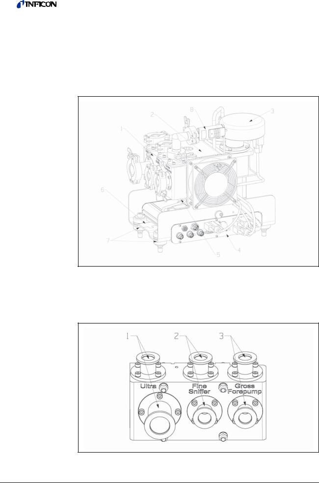
4.1Construction of the unit
Fig: 1 Mass spectrometer module LDS3000
1 - Terminal block
Connections for test system, backing pump, PIRANI gauge, internal calibration leak and sniffer line.
1: Connection ULTRA, 2: Connection FINE/SNIFFER, 3: Connection GROSS/FOREPUMP
Fig: 2 Connection block
10 Description
2- Turbo molecular pump
Turbo molecular pump with cooling unit
3 - Pre-amplifier
Pre-amplifier of the mass spectrometer module
4 - MSB box
Interfaces of the mass spectrometer module (see Chapter 4.1.1, page 11)
5 - Inverter turbo molecular pump
Electronic controller of the turbo molecular pump
6 - Rating plate
Rating plate containing mass spectrometer module specifications
7 - Fasteners
Fasteners for installing the mass spectrometer module in a test system
8 - PIRANI pressure measurement location
PIRANI gauge for measuring the pressure of the backing pump
4.1.1MSB box
Fig: 3 MSB box connections
1 - OUTPUT
Connection for gas ballast and three valves (not used, reserve)
Connection plug arrangement
1Valve 2 (gas ballast), 24 V, max. 1 A
2Valve 3 (not used)
3Valve 4 (not used)
4Valve 6 (not used)
5GND
2 - SNIFFER
Electrical connection for the sniffer line
Description 11

3 - GAUGES, EXT
Connection for optional external pressure measurement locations (0 ... 10 V or 0 … 20 mA) for INFICON Service
Connection plug arrangement
1 |
+24 V output, max. 200 mA |
2 |
Input for P3 service gauge, 0 ... 10 V |
3 |
GND |
4 |
Reference to input for P3 service gauge |
5 |
20 mA input for P3 service gauge |
4 - 1
Connection for PIRANI gauge, test leak and suppressor on the pre-amplifier (premounted, three-core cable)
5 - 24VDC
Connection for 24 V power supply pack used to supply mass spectrometer module, control unit, I/O module and bus module.
6 - 2
Connection for inverter turbo molecular pump and fan turbo molecular pump (premounted, two-core cable)
7 - ION SOURCE
Connection for ion source
8 - 3
Connection for pre-amplifier
9- 
Power LED
The Power LED and Status LED indicate the status of the unit; see no. 12 - STATUS.
10- SERVICE
RS232 connection for INFICON Service
11 - I/O / ANYBUS
Connection for I/O or bus module or control unit
Information The connections I/O / ANYBUS and CONTROL UNIT have the same functions. You have the choice of connecting:
–Control unit CU1000 + I/O module IO1000 or
–Control unit CU1000 + bus module BM1000 or
–I/O module IO1000 + bus module BM1000 or
–2 control units CU1000 or
–2 I/O modules IO1000 (configurable only together)
12 Description

12 - STATUS
Status LED
The Power LED and Status LED indicate the status of the unit.
Power LED |
Status LED |
Meaning |
|
Off |
Red |
Device not ready for operation |
|
Green |
Blue |
Turbo molecular pump is starting |
|
Green |
Orange |
Emission is switched on |
|
Green |
Green |
Emission is stable |
|
Green |
Violet |
Speed of the turbo molecular pump is |
|
not within the normal range |
|||
|
|
||
Green |
Error codes of the |
Different activities of the unit |
|
status LED |
|||
|
|
||
Green, flashes slowly |
|
Supply voltage < 21.6 V |
|
Green, flashes fast |
|
Supply voltage > 26.4 V |
|
Green, flashes fast |
Off |
Software is being updated |
|
Green |
Green, flashes fast |
Software is being updated |
13 - CONTROL UNIT
Connection for control unit or I/O or bus module
Information The connections CONTROL UNIT and I/O / ANYBUS have the same functions. You have the choice of connecting:
–Control unit CU1000 + I/O module IO1000 or
–Control unit CU1000 + bus module BM1000 or
–I/O module IO1000 + bus module BM1000 or
–2 control units CU1000 or
–2 I/O modules IO1000 (configurable only together)
4.2Function
The mass spectrometer module is a detection device for the test gases helium and hydrogen. Integrated in test systems, the unit is used to detect gas being emitted from a test object in order to indicate leaks.
The unit can be used both as a vacuum leak detector and a sniffer leak detector.
The MSB box outputs data on digital interfaces to the control unit CU1000, I/O module IO1000 or bus module BM1000.
4.3 |
Technical data |
|
|
4.3.1 |
Mechanical data |
|
|
|
|
|
|
|
|
Dimensions (W x H x D) |
320 mm x 280 mm x 240 mm |
|
|
|
|
|
|
Weight |
14.3 kg |
|
|
|
|
|
|
Connection GROSS/FOREPUMP |
2 x DN 16 |
|
|
|
|
|
|
Connection FINE/SNIFFER |
2 x DN 16 |
|
|
|
|
|
|
Connection ULTRA |
DN 16 and DN 25 |
|
|
|
|
Description 13

4.3.2 |
Electrical data |
|
|
|
||
|
|
|
|
|
|
|
|
|
Supply voltage |
24 V ± 10% DC |
|
|
|
|
|
|
|
|
|
|
|
|
Power input |
max. 10 A |
|
|
|
|
|
|
|
|
|
|
4.3.3 |
Physical data |
|
|
|
||
|
|
|
|
|
|
|
|
|
Noise level |
< 60 dB(A) |
|
|
|
|
|
|
|
|
|
|
|
|
Detectable gases |
4He, H , Mass 3 (e. g. H-D, 3He or H |
3 |
) |
|
|
|
|
|
2 |
|
|
|
|
Max. inlet pressure |
|
|
|
|
|
|
(varying with the operation mode and |
0.2 mbar ... 18 mbar |
|
|
|
|
|
the speed of the turbo molecular |
|
|
|
|
|
|
pump) |
|
|
|
|
|
|
|
|
|
|
|
|
|
Operation in vacuum mode |
|
|
|
|
|
|
|
|
|
|
|
|
|
Minimum detectable leak rate |
|
|
|
|
|
|
(varying with the operation mode and |
|
|
|
|
|
|
the speed of the turbo molecular |
|
|
|
|
|
|
pump): |
|
|
|
|
|
|
|
|
|
|
|
|
|
Helium |
< 5 x 10-12 mbar·l/s |
|
|
|
|
|
Time until ready for operation |
150 s |
|
|
|
|
|
|
|
|
|
|
|
|
Operation in Sniffer mode |
|
|
|
|
|
|
|
|
|
|
|
|
|
Minimum detectable leak rate: |
|
|
|
|
|
|
|
|
|
|
|
|
|
Helium |
< 1 x 10⁻⁷ mbar·l/s |
|
|
|
|
|
Response time in Sniffer mode |
GROSS: < 5 s, FINE/ULTRA: < 1 s |
|
|
|
|
|
|
|
|
|
|
4.3.4 |
Ambient conditions |
|
|
|
||
|
|
|
|
|
|
|
|
|
Permissible ambient temperature |
10 °C ... 45 °C |
|
|
|
|
|
(during operation) |
|
|
||
|
|
|
|
|
||
|
|
|
|
|
|
|
|
|
Permissible storage temperature |
-20 °C ... 60 °C |
|
|
|
|
|
|
|
|
|
|
|
|
Max. relative humidity |
|
|
|
|
|
|
|
|
|
|
|
|
|
|
< +31 °C |
80% |
|
|
|
|
|
|
|
|
|
|
|
at temperatures: |
+31 °C to +40 °C |
decreasing linearly from 80% ... 50% |
|
|
|
|
|
|
|
|
|
|
|
|
> +40 °C |
50% |
|
|
|
|
|
|
|
|
|
|
|
Type of protection |
IP 40 |
|
|
|
|
|
|
|
|
|
|
|
|
Pollution degree |
II |
|
|
|
|
|
|
|
|
|
|
|
|
Max. altitude above sea level |
2000 m |
|
|
|
|
|
|
|
|
|
|
|
|
Max. induction |
7 mT |
|
|
|
|
|
|
|
|
|
|
14 Description

4.3.5 |
Factory settings |
|
|
|
|
|
|
|
|
Parameter |
Factory setting |
|
|
|
|
|
|
Operation mode |
Vacuum |
|
|
|
|
|
|
Bus module address |
126 |
|
|
|
|
|
|
Pressure capillary surveillance (min.) |
0.4 mbar |
|
|
|
|
|
|
Pressure capillary surveillance (max.) |
2 mbar |
|
|
|
|
|
|
Pressure unit |
mbar |
|
|
|
|
|
|
Emission |
On |
|
|
|
|
|
|
Upper limit exponent |
1 x 10⁻⁵ |
|
|
Filter leak rate threshold |
1 x 10⁻¹⁰ |
|
|
Filter zero time |
5 s |
|
|
|
|
|
|
Filter mode |
I•CAL |
|
|
|
|
|
|
Gas ballast |
Off |
|
|
|
|
|
|
I/O module protocol |
ASCII |
|
|
|
|
|
|
Calibration request |
Off |
|
|
|
|
|
|
Calibr. factor xxx Mx |
1 |
|
|
|
|
|
|
Calibration factor VAC/SNIF Mx |
1.0 |
|
|
(for vacuum, sniffer and all masses) |
|
|
|
|
|
|
|
|
|
|
|
Cathode selection |
Auto Cat1 |
|
|
|
|
|
|
Compatibility mode |
LDS3000 |
|
|
|
|
|
|
Config. Analog output 1 |
Leak rate mantissa |
|
|
|
|
|
|
Config. Analog output 2 |
Leak rate exponent |
|
|
|
|
|
|
Config. Analog output scale |
0.5 V / decade |
|
|
|
|
|
|
|
Pin 1: Trigger 1, inverted |
|
|
|
Pin 2: Trigger 2, inverted |
|
|
|
Pin 3: Trigger 3, inverted |
|
|
Configuration dig. outputs |
Pin 4: Trigger 4, inverted |
|
|
Pin 5: Ready |
|
|
|
|
|
|
|
|
Pin 6: Error, inverted |
|
|
|
Pin 7: CAL request, inverted |
|
|
|
Pin 8: Open, inverted |
|
|
|
|
|
|
|
Pin 1: Select dyn. / normal CAL |
|
|
|
Pin 2: Sniff |
|
|
|
Pin 3: Start/Stop, inverted |
|
|
|
Pin 4: Zero |
|
|
Configuration dig. Inputs |
Pin 5: External CAL |
|
|
Pin 6: Internal CAL |
|
|
|
|
|
|
|
|
Pin 7: Clear |
|
|
|
Pin 8: - |
|
|
|
Pin 9: - |
|
|
|
Pin 10: - |
|
|
|
|
|
|
Leak rate unit SNIFF |
mbar*l/s |
|
|
|
|
|
|
Leak rate unit VAC |
mbar*l/s |
|
|
|
|
Description 15

Parameter |
Factory setting |
|
|
Fan mode |
Fan always on |
|
|
Machine factor in standby |
Off |
|
|
Machine factor / Sniff factor |
1.0 (for all masses) |
|
|
Mass |
4 |
|
|
Maximum pressure VAC |
18 mbar |
|
|
Module at I/O connector |
IO1000 |
|
|
Nominal state TMP |
On |
|
|
Test leak external SNIF |
9.9 x 10⁻² |
Test leak external VAC |
9.9 x 10⁻² |
Test leak internal |
9.9 x 10⁻² |
Sniff factor |
1.0 (for all masses) |
|
|
TMP speed |
1500 |
|
|
Trigger 1/2/3/4 level |
1 x 10⁻⁵ mbar·l/s |
M |
Off |
|
|
Zero with Start |
Off |
|
|
Zero mode |
Normal |
|
|
Zero key sniffer |
On |
|
|
16 Description
 Loading...