


 Loading...
O P E R A T I N G M A N U A L
IC/5
Thin Film Deposition Controller
IPN 074-237AE

O P E R A T I N G M A N U A L
IC/5
Thin Film Deposition Controller
IPN 074-237AE
www.inficon.com reachus@inficon.com
Due to our continuing program of product improvements, specifications are subject to change without notice.
©2001 INFICON
Trademarks
The trademarks of the products mentioned in this Operating Manual are held by the companies that produce them.
INFICON® is a trademark of INFICON Inc.
Windows®, Windows 95® and Microsoft® are registered trademarks of Microsoft Corporation.
CAJON® is a registered trademark of Swagelok, Co.
All other brand and product names are trademarks or registered trademarks of their respective companies.
The information contained in this Operating Manual is believed to be accurate and reliable. However, INFICON assumes no responsibility for its use and shall not be liable for any special, incidental, or consequential damages related to the use of this product.
Due to our continuing program of product improvements, specifications are subject to change without notice.
©2001 All rights reserved.
Reproduction or adaptation of any part of this document without permission is unlawful.

DECLARATION
OF
CONFORMITY
This is to certify that this equipment, designed and manufactured by:
INFICON Inc.
2 Technology Place
East Syracuse, NY 13057
USA
meets the essential safety requirements of the European Union and is placed on the market accordingly. It has been constructed in accordance with good engineering practice in safety matters in force in the Community and does not endanger the safety of persons, domestic animals or property when properly installed and maintained and used in applications for which it was made.
Equipment Description: |
IC/5 Thin Film Deposition Controllers, including |
||
|
Oscillators and Crystal Sensors as properly installed. |
||
Applicable Directives: |
73/23/EEC as amended by 93/68/EEC |
||
|
89/336/EEC as amended by 93/68/EEC |
||
Applicable Standards: |
EN 61010-1 : 1993 |
|
|
|
EN 55011, Group 1, Class A : 1991 |
|
|
|
EN 50082-1 : 1992 |
|
|
CE Implementation Date: |
January 2, 1996 |
||
Authorized Representative: |
Gary W. Lewis |
||
|
Vice President - Quality Assurance |
||
|
INFICON Inc. |
||
ANY QUESTIONS RELATIVE TO THIS DECLARATION OR TO THE SAFETY OF INFICON'S PRODUCTS SHOULD BE DIRECTED, IN WRITING, TO THE QUALITY ASSURANCE DEPARTMENT AT THE ABOVE ADDRESS.
01/16/96

Warranty
WARRANTY AND LIABILITY - LIMITATION: Seller warrants the products manufactured by it, or by an affiliated company and sold by it, and described on the reverse hereof, to be, for the period of warranty coverage specified below, free from defects of materials or workmanship under normal proper use and service. The period of warranty coverage is specified for the respective products in the respective Seller instruction manuals for those products but shall not be less than two (2) years from the date of shipment thereof by Seller. Seller's liability under this warranty is limited to such of the above products or parts thereof as are returned, transportation prepaid, to Seller's plant, not later than thirty (30) days after the expiration of the period of warranty coverage in respect thereof and are found by Seller's examination to have failed to function properly because of defective workmanship or materials and not because of improper installation or misuse and is limited to, at Seller's election, either (a) repairing and returning the product or part thereof, or (b) furnishing a replacement product or part thereof, transportation prepaid by Seller in either case. In the event Buyer discovers or learns that a product does not conform to warranty, Buyer shall immediately notify Seller in writing of such non-conformity, specifying in reasonable detail the nature of such non-conformity. If Seller is not provided with such written notification, Seller shall not be liable for any further damages which could have been avoided if Seller had been provided with immediate written notification.
THIS WARRANTY IS MADE AND ACCEPTED IN LIEU OF ALL OTHER WARRANTIES, EXPRESS OR IMPLIED, WHETHER OF MERCHANTABILITY OR OF FITNESS FOR A PARTICULAR PURPOSE OR OTHERWISE, AS BUYER'S EXCLUSIVE REMEDY FOR ANY DEFECTS IN THE PRODUCTS TO BE SOLD HEREUNDER. All other obligations and liabilities of Seller, whether in contract or tort (including negligence) or otherwise, are expressly EXCLUDED. In no event shall Seller be liable for any costs, expenses or damages, whether direct or indirect, special, incidental, consequential, or other, on any claim of any defective product, in excess of the price paid by Buyer for the product plus return transportation charges prepaid.
No warranty is made by Seller of any Seller product which has been installed, used or operated contrary to Seller's written instruction manual or which has been subjected to misuse, negligence or accident or has been repaired or altered by anyone other than Seller or which has been used in a manner or for a purpose for which the Seller product was not designed nor against any defects due to plans or instructions supplied to Seller by or for Buyer.
This manual is intended for private use by INFICON® Inc. and its customers. Contact INFICON before reproducing its contents.
NOTE: These instructions do not provide for every contingency that may arise in connection with the installation, operation or maintenance of this equipment. Should you require further assistance, please contact INFICON.
www.inficon.com reachus@inficon.com

IPN 074-237AE
IC/5 Operating Manual
Table Of Contents
Chapter 1
Introduction and Specifications
1.1 Introduction. . . . . . . . . . . . . . . . . . . . . . . . . . . . . . . . . . . . . . . . . . . . . . . . . . 1-1 1.1.1 Related Manuals. . . . . . . . . . . . . . . . . . . . . . . . . . . . . . . . . . . . . . . . . . . . . . 1-1 1.2 Instrument Safety . . . . . . . . . . . . . . . . . . . . . . . . . . . . . . . . . . . . . . . . . . . . . 1-2 1.2.1 Definition of Notes, Cautions and Warnings. . . . . . . . . . . . . . . . . . . . . . . . . 1-2 1.2.2 General Safety Information. . . . . . . . . . . . . . . . . . . . . . . . . . . . . . . . . . . . . . 1-3 1.2.3 Earth Ground . . . . . . . . . . . . . . . . . . . . . . . . . . . . . . . . . . . . . . . . . . . . . . . . 1-4 1.2.4 Main Power Connection . . . . . . . . . . . . . . . . . . . . . . . . . . . . . . . . . . . . . . . . 1-5 1.3 How To Contact Customer Support . . . . . . . . . . . . . . . . . . . . . . . . . . . . . . . 1-6 1.3.1 Returning Your Instrument . . . . . . . . . . . . . . . . . . . . . . . . . . . . . . . . . . . . . . 1-6 1.4 IC/5 Specifications . . . . . . . . . . . . . . . . . . . . . . . . . . . . . . . . . . . . . . . . . . . . 1-7 1.4.1 Measurement . . . . . . . . . . . . . . . . . . . . . . . . . . . . . . . . . . . . . . . . . . . . . . . . 1-7 1.4.2 Screens and Hierarchy . . . . . . . . . . . . . . . . . . . . . . . . . . . . . . . . . . . . . . . . . 1-7 1.4.3 Set-Up Parameters. . . . . . . . . . . . . . . . . . . . . . . . . . . . . . . . . . . . . . . . . . . . 1-8 1.4.4 Display . . . . . . . . . . . . . . . . . . . . . . . . . . . . . . . . . . . . . . . . . . . . . . . . . . . . 1-10 1.4.5 Source / Recorder Outputs. . . . . . . . . . . . . . . . . . . . . . . . . . . . . . . . . . . . . 1-11 1.4.6 Logic Processing . . . . . . . . . . . . . . . . . . . . . . . . . . . . . . . . . . . . . . . . . . . . 1-12 1.4.7 Relays / Inputs . . . . . . . . . . . . . . . . . . . . . . . . . . . . . . . . . . . . . . . . . . . . . . 1-12 1.4.8 Remote Communications . . . . . . . . . . . . . . . . . . . . . . . . . . . . . . . . . . . . . . 1-13 1.4.9 Accessories . . . . . . . . . . . . . . . . . . . . . . . . . . . . . . . . . . . . . . . . . . . . . . . . 1-13 1.4.10 Power . . . . . . . . . . . . . . . . . . . . . . . . . . . . . . . . . . . . . . . . . . . . . . . . . . . . . 1-13 1.4.11 Operating Environment. . . . . . . . . . . . . . . . . . . . . . . . . . . . . . . . . . . . . . . . 1-14 1.4.12 Storage Temperature . . . . . . . . . . . . . . . . . . . . . . . . . . . . . . . . . . . . . . . . . 1-14 1.4.13 Warm Up Period . . . . . . . . . . . . . . . . . . . . . . . . . . . . . . . . . . . . . . . . . . . . . 1-14 1.4.14 Size. . . . . . . . . . . . . . . . . . . . . . . . . . . . . . . . . . . . . . . . . . . . . . . . . . . . . . . 1-14 1.4.15 Connector Clearance Requirements . . . . . . . . . . . . . . . . . . . . . . . . . . . . . 1-14 1.4.16 Weight . . . . . . . . . . . . . . . . . . . . . . . . . . . . . . . . . . . . . . . . . . . . . . . . . . . . 1-14 1.4.17 Cleaning . . . . . . . . . . . . . . . . . . . . . . . . . . . . . . . . . . . . . . . . . . . . . . . . . . . 1-14 1.5 Unpacking and Inspection . . . . . . . . . . . . . . . . . . . . . . . . . . . . . . . . . . . . . 1-15 1.6 Parts and Options Overview. . . . . . . . . . . . . . . . . . . . . . . . . . . . . . . . . . . . 1-15 1.6.1 Base Configurations . . . . . . . . . . . . . . . . . . . . . . . . . . . . . . . . . . . . . . . . . . 1-15 1.6.2 Pre-installed Options or Spares . . . . . . . . . . . . . . . . . . . . . . . . . . . . . . . . . 1-16 1.6.3 Optional Accessories . . . . . . . . . . . . . . . . . . . . . . . . . . . . . . . . . . . . . . . . . 1-16 1.6.4 Oscillator Packages and Sensors. . . . . . . . . . . . . . . . . . . . . . . . . . . . . . . . 1-17 1.7 Initial Power-On Verification . . . . . . . . . . . . . . . . . . . . . . . . . . . . . . . . . . . . 1-18
TOC - 1

IC/5 Operating Manual
Chapter 2
Measurement and Control Theory
2.1 Basics. . . . . . . . . . . . . . . . . . . . . . . . . . . . . . . . . . . . . . . . . . . . . . . . . . . . . . 2-1
2.1.1 Monitor Crystals . . . . . . . . . . . . . . . . . . . . . . . . . . . . . . . . . . . . . . . . . . . . . . 2-2
2.1.2 Period Measurement Technique . . . . . . . . . . . . . . . . . . . . . . . . . . . . . . . . . 2-4
2.1.3 Z-match Technique . . . . . . . . . . . . . . . . . . . . . . . . . . . . . . . . . . . . . . . . . . . 2-5
2.1.4 Active Oscillator . . . . . . . . . . . . . . . . . . . . . . . . . . . . . . . . . . . . . . . . . . . . . . 2-6
2.1.5 ModeLock Oscillator. . . . . . . . . . . . . . . . . . . . . . . . . . . . . . . . . . . . . . . . . . . 2-7
2.1.6 Auto Z-match Theory . . . . . . . . . . . . . . . . . . . . . . . . . . . . . . . . . . . . . . . . . . 2-9
2.1.7 Control Loop Theory. . . . . . . . . . . . . . . . . . . . . . . . . . . . . . . . . . . . . . . . . . 2-11
Chapter 3
Operation
3.1 Front Panel Controls . . . . . . . . . . . . . . . . . . . . . . . . . . . . . . . . . . . . . . . . . . 3-1 3.2 Rear Panel Interfaces. . . . . . . . . . . . . . . . . . . . . . . . . . . . . . . . . . . . . . . . . . 3-3 3.3 Displays . . . . . . . . . . . . . . . . . . . . . . . . . . . . . . . . . . . . . . . . . . . . . . . . . . . . 3-5 3.3.1 Display Navigation via the MENU TREE . . . . . . . . . . . . . . . . . . . . . . . . . . . 3-8 3.3.2 Operate Display . . . . . . . . . . . . . . . . . . . . . . . . . . . . . . . . . . . . . . . . . . . . . . 3-9 3.3.2.1 Crystal Life and Starting Frequency . . . . . . . . . . . . . . . . . . . . . . . . . . . . . . 3-12 3.3.3 Sensors Display . . . . . . . . . . . . . . . . . . . . . . . . . . . . . . . . . . . . . . . . . . . . . 3-13 3.3.3.1 SENSORS Display Description . . . . . . . . . . . . . . . . . . . . . . . . . . . . . . . . . 3-13
3.3.3.2Function Key Selection Choices for
the Sensors Display . . . . . . . . . . . . . . . . . . . . . . . . . . . . . . . . . . . . . . . . . . 3-16
3.3.4 Maintenance/Diagnostics Display . . . . . . . . . . . . . . . . . . . . . . . . . . . . . . . 3-17
3.3.4.1Function Key Selection Choices for the
Maintenance/Diagnostics Display . . . . . . . . . . . . . . . . . . . . . . . . . . . . . . . 3-17
3.3.5 Source Maintenance Display . . . . . . . . . . . . . . . . . . . . . . . . . . . . . . . . . . . 3-18
3.3.5.1Function Key Selection Choices for the
Source Maintenance Display . . . . . . . . . . . . . . . . . . . . . . . . . . . . . . . . . . . 3-18 3.3.6 Cross Talk and Calibration Display . . . . . . . . . . . . . . . . . . . . . . . . . . . . . . 3-19 3.3.7 Program Displays . . . . . . . . . . . . . . . . . . . . . . . . . . . . . . . . . . . . . . . . . . . . 3-20 3.3.7.1 Function Key Selection Choices for the Program Display . . . . . . . . . . . . . 3-20 3.4 Process Description . . . . . . . . . . . . . . . . . . . . . . . . . . . . . . . . . . . . . . . . . . 3-22 3.4.1 Defining a Process . . . . . . . . . . . . . . . . . . . . . . . . . . . . . . . . . . . . . . . . . . . 3-22 3.4.2 Executing a Process. . . . . . . . . . . . . . . . . . . . . . . . . . . . . . . . . . . . . . . . . . 3-23 3.4.3 Pre-conditioning a Layer . . . . . . . . . . . . . . . . . . . . . . . . . . . . . . . . . . . . . . 3-25 3.4.4 Co-deposition . . . . . . . . . . . . . . . . . . . . . . . . . . . . . . . . . . . . . . . . . . . . . . . 3-26 3.4.5 Automating a Process . . . . . . . . . . . . . . . . . . . . . . . . . . . . . . . . . . . . . . . . 3-27 3.5 State Descriptions . . . . . . . . . . . . . . . . . . . . . . . . . . . . . . . . . . . . . . . . . . . 3-30
TOC - 2
IPN 074-237AE
IPN 074-237AE
IC/5 Operating Manual
3.6 Special Features. . . . . . . . . . . . . . . . . . . . . . . . . . . . . . . . . . . . . . . . . . . . . 3-32
3.6.1 Crystal Switching . . . . . . . . . . . . . . . . . . . . . . . . . . . . . . . . . . . . . . . . . . . . 3-32
3.6.1.1 CrystalSix Position Select. . . . . . . . . . . . . . . . . . . . . . . . . . . . . . . . . . . . . . 3-33
3.6.1.2 Rotary Sensor Crystal Switching . . . . . . . . . . . . . . . . . . . . . . . . . . . . . . . . 3-33
3.6.2 Source/Crucible Selection . . . . . . . . . . . . . . . . . . . . . . . . . . . . . . . . . . . . . 3-34
3.6.2.1 Example: Programming Turret Source Crucible Selection . . . . . . . . . . . . . 3-34
3.6.3 Auto Z . . . . . . . . . . . . . . . . . . . . . . . . . . . . . . . . . . . . . . . . . . . . . . . . . . . . . 3-36
3.6.4 Auto Tune - Optimizing the Control Loop . . . . . . . . . . . . . . . . . . . . . . . . . . 3-37
3.6.5 Rate Watcher . . . . . . . . . . . . . . . . . . . . . . . . . . . . . . . . . . . . . . . . . . . . . . . 3-37
3.6.6 Hand-Held Controller . . . . . . . . . . . . . . . . . . . . . . . . . . . . . . . . . . . . . . . . . 3-38
3.6.7 Test Mode. . . . . . . . . . . . . . . . . . . . . . . . . . . . . . . . . . . . . . . . . . . . . . . . . . 3-39
3.6.8 Floppy Disk (Optional) . . . . . . . . . . . . . . . . . . . . . . . . . . . . . . . . . . . . . . . . 3-39
3.6.9 Lock and Access Codes . . . . . . . . . . . . . . . . . . . . . . . . . . . . . . . . . . . . . . . 3-40
3.6.10 Datalog . . . . . . . . . . . . . . . . . . . . . . . . . . . . . . . . . . . . . . . . . . . . . . . . . . . . 3-40
Chapter 4
Material Set Up
4.1 Material Set Up Overview. . . . . . . . . . . . . . . . . . . . . . . . . . . . . . . . . . . . . . . 4-1
4.2 Material Definition. . . . . . . . . . . . . . . . . . . . . . . . . . . . . . . . . . . . . . . . . . . . . 4-1
4.3 Material Definition Parameters . . . . . . . . . . . . . . . . . . . . . . . . . . . . . . . . . . . 4-5
4.4 Error Messages in Material Set-Up . . . . . . . . . . . . . . . . . . . . . . . . . . . . . . 4-15
Chapter 5
Process Set-Up
5.1 Process Set-Up Overview . . . . . . . . . . . . . . . . . . . . . . . . . . . . . . . . . . . . . . 5-1
5.2 Process Definition. . . . . . . . . . . . . . . . . . . . . . . . . . . . . . . . . . . . . . . . . . . . . 5-2
5.2.1 Layer Editing. . . . . . . . . . . . . . . . . . . . . . . . . . . . . . . . . . . . . . . . . . . . . . . . . 5-3
5.3 Layer Definition Parameters . . . . . . . . . . . . . . . . . . . . . . . . . . . . . . . . . . . . . 5-4
5.4 Error Messages in Process Set-Up . . . . . . . . . . . . . . . . . . . . . . . . . . . . . . . 5-8
5.5 Special Layer Parameter Features. . . . . . . . . . . . . . . . . . . . . . . . . . . . . . . . 5-9
5.5.1 Skip Deposit . . . . . . . . . . . . . . . . . . . . . . . . . . . . . . . . . . . . . . . . . . . . . . . . . 5-9
5.5.2 Rate Ramp Trigger of Final Thickness . . . . . . . . . . . . . . . . . . . . . . . . . . . . . 5-9
Chapter 6
I/O Logic Statement Set-Up
6.1 I/O Logic Statement Overview . . . . . . . . . . . . . . . . . . . . . . . . . . . . . . . . . . . 6-1
6.2 Editing the Logic Statements . . . . . . . . . . . . . . . . . . . . . . . . . . . . . . . . . . . . 6-2
6.2.1 Logic Statement Directory . . . . . . . . . . . . . . . . . . . . . . . . . . . . . . . . . . . . . . 6-3
6.2.2 Logic Statement Editing . . . . . . . . . . . . . . . . . . . . . . . . . . . . . . . . . . . . . . . . 6-4
6.3 ’IF’ Event Definitions. . . . . . . . . . . . . . . . . . . . . . . . . . . . . . . . . . . . . . . . . . . 6-6
6.4 ’THEN’ Action Definitions . . . . . . . . . . . . . . . . . . . . . . . . . . . . . . . . . . . . . . 6-12
TOC - 3

IC/5 Operating Manual
6.5 Logic Statement Example . . . . . . . . . . . . . . . . . . . . . . . . . . . . . . . . . . . . . 6-15
6.6 I/O Map Directory . . . . . . . . . . . . . . . . . . . . . . . . . . . . . . . . . . . . . . . . . . . . 6-16
6.7 Define User Messages . . . . . . . . . . . . . . . . . . . . . . . . . . . . . . . . . . . . . . . . 6-17
6.8 Floppy Disk. . . . . . . . . . . . . . . . . . . . . . . . . . . . . . . . . . . . . . . . . . . . . . . . . 6-19
6.9Error Messages in I/O
Logic Statement Set-Up . . . . . . . . . . . . . . . . . . . . . . . . . . . . . . . . . . . . . . . 6-21
Chapter 7
Remote Communications
7.1Remote Communication
Configuration Overview . . . . . . . . . . . . . . . . . . . . . . . . . . . . . . . . . . . . . . . . 7-1
7.2 Remote Communication Parameters . . . . . . . . . . . . . . . . . . . . . . . . . . . . . . 7-2
7.3Error Messages in
Remote Communications Configuration. . . . . . . . . . . . . . . . . . . . . . . . . . . . 7-4 7.4 Remote Communications Overview . . . . . . . . . . . . . . . . . . . . . . . . . . . . . . . 7-4 7.5 Physical Connections . . . . . . . . . . . . . . . . . . . . . . . . . . . . . . . . . . . . . . . . . . 7-4 7.5.1 RS-232C Serial Port. . . . . . . . . . . . . . . . . . . . . . . . . . . . . . . . . . . . . . . . . . . 7-5 7.5.2 IEEE488 Port . . . . . . . . . . . . . . . . . . . . . . . . . . . . . . . . . . . . . . . . . . . . . . . . 7-7 7.5.2.1 IEEE Settings for a National Instruments IEEE-GPIB Board . . . . . . . . . . . . 7-8 7.6 Message Protocols. . . . . . . . . . . . . . . . . . . . . . . . . . . . . . . . . . . . . . . . . . . . 7-8 7.6.1 INFICON Message Formats. . . . . . . . . . . . . . . . . . . . . . . . . . . . . . . . . . . . . 7-9
7.7INFICON Standard
Communication Commands . . . . . . . . . . . . . . . . . . . . . . . . . . . . . . . . . . . . 7-10
7.7.1 ECHO Command . . . . . . . . . . . . . . . . . . . . . . . . . . . . . . . . . . . . . . . . . . . . 7-10
7.7.2 HELLO Command . . . . . . . . . . . . . . . . . . . . . . . . . . . . . . . . . . . . . . . . . . . 7-10
7.7.3 Query Commands . . . . . . . . . . . . . . . . . . . . . . . . . . . . . . . . . . . . . . . . . . . 7-11
7.7.3.1 Query Material Parameters . . . . . . . . . . . . . . . . . . . . . . . . . . . . . . . . . . . . 7-11
7.7.3.2 Query Process Parameters . . . . . . . . . . . . . . . . . . . . . . . . . . . . . . . . . . . . 7-14
7.7.3.3 Query Utility Parameters . . . . . . . . . . . . . . . . . . . . . . . . . . . . . . . . . . . . . . 7-15
7.7.3.4 Query Sensor Parameters . . . . . . . . . . . . . . . . . . . . . . . . . . . . . . . . . . . . . 7-16
7.7.3.5 Query Source Parameters . . . . . . . . . . . . . . . . . . . . . . . . . . . . . . . . . . . . . 7-16
7.7.3.6 Query Output Types . . . . . . . . . . . . . . . . . . . . . . . . . . . . . . . . . . . . . . . . . . 7-17
7.7.3.7 Query Logic Statements. . . . . . . . . . . . . . . . . . . . . . . . . . . . . . . . . . . . . . . 7-17
7.7.3.8 Query Output Name . . . . . . . . . . . . . . . . . . . . . . . . . . . . . . . . . . . . . . . . . . 7-17
7.7.3.9 Query Input Name . . . . . . . . . . . . . . . . . . . . . . . . . . . . . . . . . . . . . . . . . . . 7-17
7.7.3.10 Query User Messages . . . . . . . . . . . . . . . . . . . . . . . . . . . . . . . . . . . . . . . . 7-17
7.7.4 UPDATE Commands . . . . . . . . . . . . . . . . . . . . . . . . . . . . . . . . . . . . . . . . . 7-18
7.7.4.1 Update Material Parameters . . . . . . . . . . . . . . . . . . . . . . . . . . . . . . . . . . . 7-18
7.7.4.2 Update Process Parameters . . . . . . . . . . . . . . . . . . . . . . . . . . . . . . . . . . . 7-21
7.7.4.3 Update Utility Parameters . . . . . . . . . . . . . . . . . . . . . . . . . . . . . . . . . . . . . 7-22
TOC - 4
IPN 074-237AE

IPN 074-237AE
IC/5 Operating Manual
7.7.4.4 Update Sensor Parameters . . . . . . . . . . . . . . . . . . . . . . . . . . . . . . . . . . . . 7-23
7.7.4.5 Update Source Parameters . . . . . . . . . . . . . . . . . . . . . . . . . . . . . . . . . . . . 7-23
7.7.4.6 Update Output Types . . . . . . . . . . . . . . . . . . . . . . . . . . . . . . . . . . . . . . . . . 7-24
7.7.4.7 Update Logic Statements . . . . . . . . . . . . . . . . . . . . . . . . . . . . . . . . . . . . . . 7-24
7.7.4.8 Update Output Name . . . . . . . . . . . . . . . . . . . . . . . . . . . . . . . . . . . . . . . . . 7-27
7.7.4.9 Update Input Name . . . . . . . . . . . . . . . . . . . . . . . . . . . . . . . . . . . . . . . . . . 7-27
7.7.4.10 Update User Message . . . . . . . . . . . . . . . . . . . . . . . . . . . . . . . . . . . . . . . . 7-27
7.7.5 STATUS Commands . . . . . . . . . . . . . . . . . . . . . . . . . . . . . . . . . . . . . . . . . 7-28
7.7.6 REMOTE Commands. . . . . . . . . . . . . . . . . . . . . . . . . . . . . . . . . . . . . . . . . 7-38
7.7.7 Negative Response Error Codes . . . . . . . . . . . . . . . . . . . . . . . . . . . . . . . . 7-41
7.8Sample INFICON Messages and
Host Programs . . . . . . . . . . . . . . . . . . . . . . . . . . . . . . . . . . . . . . . . . . . . . . 7-41 7.8.1 Sample INFICON Messages . . . . . . . . . . . . . . . . . . . . . . . . . . . . . . . . . . . 7-41 7.8.2 Sample Host Programs . . . . . . . . . . . . . . . . . . . . . . . . . . . . . . . . . . . . . . . 7-43 7.8.2.1 Serial Communications - No Checksum. . . . . . . . . . . . . . . . . . . . . . . . . . . 7-43 7.8.2.2 Serial Communication with Checksum . . . . . . . . . . . . . . . . . . . . . . . . . . . . 7-44 7.8.2.3 IEEE Sample Host Program . . . . . . . . . . . . . . . . . . . . . . . . . . . . . . . . . . . . 7-45
Chapter 8
Source/Sensor Set-Up
8.1 Source/Sensor Set-Up Overview . . . . . . . . . . . . . . . . . . . . . . . . . . . . . . . . . 8-1
8.2 Source/Sensor Navigation . . . . . . . . . . . . . . . . . . . . . . . . . . . . . . . . . . . . . . 8-2
8.3 Source Parameters. . . . . . . . . . . . . . . . . . . . . . . . . . . . . . . . . . . . . . . . . . . . 8-3
8.4 Sensor Parameters. . . . . . . . . . . . . . . . . . . . . . . . . . . . . . . . . . . . . . . . . . . . 8-6
8.5 DAC Output Selection Rules . . . . . . . . . . . . . . . . . . . . . . . . . . . . . . . . . . . . 8-8
8.6 Error Messages in Source/Sensor Set-Up . . . . . . . . . . . . . . . . . . . . . . . . . . 8-9
Chapter 9
Utility Set-Up
9.1 Utility Set-Up Overview. . . . . . . . . . . . . . . . . . . . . . . . . . . . . . . . . . . . . . . . . 9-1
9.2 Utility Navigation. . . . . . . . . . . . . . . . . . . . . . . . . . . . . . . . . . . . . . . . . . . . . . 9-2
9.3 Utility Parameters . . . . . . . . . . . . . . . . . . . . . . . . . . . . . . . . . . . . . . . . . . . . . 9-2
9.4 Error Messages in Utility Set-Up . . . . . . . . . . . . . . . . . . . . . . . . . . . . . . . . . 9-7
Chapter 10
Applications
10.1 Multiple Sensor Deposition Control . . . . . . . . . . . . . . . . . . . . . . . . . . . . . . 10-1
10.1.1Instrument Parameters and Corrections for
Multiple Sensor Operation . . . . . . . . . . . . . . . . . . . . . . . . . . . . . . . . . . . . . 10-2 10.2 Trend Analysis . . . . . . . . . . . . . . . . . . . . . . . . . . . . . . . . . . . . . . . . . . . . . . 10-4 10.2.1 Instrument Parameters Associated with the Trend Analysis Feature. . . . . 10-5
TOC - 5

IC/5 Operating Manual
10.3 Use as a System Controller Example. . . . . . . . . . . . . . . . . . . . . . . . . . . . . 10-5 10.3.1 System Equipment List. . . . . . . . . . . . . . . . . . . . . . . . . . . . . . . . . . . . . . . . 10-8 10.3.1.1 Valves. . . . . . . . . . . . . . . . . . . . . . . . . . . . . . . . . . . . . . . . . . . . . . . . . . . . . 10-8 10.3.1.2 Switches . . . . . . . . . . . . . . . . . . . . . . . . . . . . . . . . . . . . . . . . . . . . . . . . . . . 10-8 10.3.1.3 Solenoid Valves . . . . . . . . . . . . . . . . . . . . . . . . . . . . . . . . . . . . . . . . . . . . . 10-9 10.3.1.4 Electron Beam Gun Power Supply. . . . . . . . . . . . . . . . . . . . . . . . . . . . . . . 10-9 10.3.1.5 Vacuum Gauges and Controllers . . . . . . . . . . . . . . . . . . . . . . . . . . . . . . . . 10-9 10.3.1.6 Temperature Sensor . . . . . . . . . . . . . . . . . . . . . . . . . . . . . . . . . . . . . . . . 10-10 10.3.1.7 Lamps. . . . . . . . . . . . . . . . . . . . . . . . . . . . . . . . . . . . . . . . . . . . . . . . . . . . 10-10 10.3.2 I/O Set-Up . . . . . . . . . . . . . . . . . . . . . . . . . . . . . . . . . . . . . . . . . . . . . . . . 10-10 10.3.2.1 Outputs Connected to I/O Board 1 . . . . . . . . . . . . . . . . . . . . . . . . . . . . . . 10-13 10.3.2.2 Outputs Connected to I/O Board 2 . . . . . . . . . . . . . . . . . . . . . . . . . . . . . . 10-14 10.3.2.3 Logic Statement Directory . . . . . . . . . . . . . . . . . . . . . . . . . . . . . . . . . . . . 10-15
Chapter 11
Installation and Interfaces
11.1 Location Guidelines . . . . . . . . . . . . . . . . . . . . . . . . . . . . . . . . . . . . . . . . . . 11-1 11.1.1 Sensor Types . . . . . . . . . . . . . . . . . . . . . . . . . . . . . . . . . . . . . . . . . . . . . . . 11-1 11.1.2 Sensor Installation . . . . . . . . . . . . . . . . . . . . . . . . . . . . . . . . . . . . . . . . . . . 11-3 11.1.3 Control Unit Installation . . . . . . . . . . . . . . . . . . . . . . . . . . . . . . . . . . . . . . . 11-5 11.2 Avoiding Electrical Interference . . . . . . . . . . . . . . . . . . . . . . . . . . . . . . . . . 11-5 11.2.1 Verifying/Establishing Earth Ground . . . . . . . . . . . . . . . . . . . . . . . . . . . . . 11-5 11.2.2 Connections to Earth Ground. . . . . . . . . . . . . . . . . . . . . . . . . . . . . . . . . . . 11-6 11.2.3 Minimizing Noise Pickup From External Cabling . . . . . . . . . . . . . . . . . . . . 11-7 11.3 Connecting the Controller. . . . . . . . . . . . . . . . . . . . . . . . . . . . . . . . . . . . . . 11-8 11.3.1 Verifying the Correct Input Voltage . . . . . . . . . . . . . . . . . . . . . . . . . . . . . . 11-8 11.3.2 Voltage Selection . . . . . . . . . . . . . . . . . . . . . . . . . . . . . . . . . . . . . . . . . . . . 11-9 11.3.3 Routing XIU Cables . . . . . . . . . . . . . . . . . . . . . . . . . . . . . . . . . . . . . . . . . 11-10 11.3.4 Interface Cable Fabrication and Pin-Out . . . . . . . . . . . . . . . . . . . . . . . . . 11-10 11.3.4.1 Source Control Connection . . . . . . . . . . . . . . . . . . . . . . . . . . . . . . . . . . . 11-10 11.3.4.2 Input/Relay Module Connections . . . . . . . . . . . . . . . . . . . . . . . . . . . . . . . 11-11 11.3.4.3 RS-232C Communications. . . . . . . . . . . . . . . . . . . . . . . . . . . . . . . . . . . . 11-13 11.3.4.4 Isolated +24 V(dc) Supply . . . . . . . . . . . . . . . . . . . . . . . . . . . . . . . . . . . . 11-14
Chapter 12
Calibration Procedures
12.1 Importance of Density, Tooling and Z-ratio . . . . . . . . . . . . . . . . . . . . . . . . 12-1
12.2 Determining Density . . . . . . . . . . . . . . . . . . . . . . . . . . . . . . . . . . . . . . . . . . 12-1
12.3 Determining Tooling . . . . . . . . . . . . . . . . . . . . . . . . . . . . . . . . . . . . . . . . . . 12-2
12.4 Laboratory Determination of Z-ratio . . . . . . . . . . . . . . . . . . . . . . . . . . . . . . 12-3
TOC - 6
IPN 074-237AE

IPN 074-237AE
IC/5 Operating Manual
12.5Determining Cross Talk Calibration
For Co-Deposition . . . . . . . . . . . . . . . . . . . . . . . . . . . . . . . . . . . . . . . . . . . 12-4
12.5.1 Procedure Set-Up. . . . . . . . . . . . . . . . . . . . . . . . . . . . . . . . . . . . . . . . . . . . 12-6
12.5.1.1 Cross Talk Calibrate Parameters . . . . . . . . . . . . . . . . . . . . . . . . . . . . . . . . 12-7
12.5.1.1.1Function Key Selection Choices for
Cross Talk Calibration Setup . . . . . . . . . . . . . . . . . . . . . . . . . . . . . . . . . . . 12-8 12.5.2 Cross Talk Calibration MANUAL display . . . . . . . . . . . . . . . . . . . . . . . . . . 12-8
12.5.2.1Function Key Selection Choices for
Cross Talk Calibration Manual . . . . . . . . . . . . . . . . . . . . . . . . . . . . . . . . . . 12-8 12.5.3 Cross Talk Calibration CALIBRATE display . . . . . . . . . . . . . . . . . . . . . . . . 12-9
12.5.3.1Function Key Selection Choices for
Cross Talk Calibration Calibrate. . . . . . . . . . . . . . . . . . . . . . . . . . . . . . . . . 12-9 12.5.4 Cross Talk Calibration SELECT display . . . . . . . . . . . . . . . . . . . . . . . . . . . 12-9
12.5.4.1Function Key Selection Choices for
Cross Talk Calibration Select . . . . . . . . . . . . . . . . . . . . . . . . . . . . . . . . . . 12-10
12.5.5 Cross Talk Calibration Procedural Notes . . . . . . . . . . . . . . . . . . . . . . . . . 12-10
12.6 AutoTuning . . . . . . . . . . . . . . . . . . . . . . . . . . . . . . . . . . . . . . . . . . . . . . . . 12-11
12.6.1 AutoTune Parameters . . . . . . . . . . . . . . . . . . . . . . . . . . . . . . . . . . . . . . . 12-12
12.6.2 AutoTune Manual Display . . . . . . . . . . . . . . . . . . . . . . . . . . . . . . . . . . . . 12-13
12.6.3AutoTune Tuning Display and
AutoTune Description . . . . . . . . . . . . . . . . . . . . . . . . . . . . . . . . . . . . . . . . 12-14
12.6.4 Definition of AutoTune Messages. . . . . . . . . . . . . . . . . . . . . . . . . . . . . . . 12-15
12.6.5 AutoTune Preparation Instructions . . . . . . . . . . . . . . . . . . . . . . . . . . . . . . 12-17
Chapter 13
Troubleshooting, Status and Error Messages
13.1 Status and Error Messages . . . . . . . . . . . . . . . . . . . . . . . . . . . . . . . . . . . . 13-1
13.2 Troubleshooting Guide . . . . . . . . . . . . . . . . . . . . . . . . . . . . . . . . . . . . . . . 13-11
13.2.1 Major Instrument Components and Assemblies. . . . . . . . . . . . . . . . . . . . 13-12
13.2.2 Troubleshooting the Instrument . . . . . . . . . . . . . . . . . . . . . . . . . . . . . . . . 13-13
13.2.3 Troubleshooting Transducers/Sensors. . . . . . . . . . . . . . . . . . . . . . . . . . . 13-15
13.2.4 Troubleshooting Computer Communications . . . . . . . . . . . . . . . . . . . . . . 13-20
13.3 Replacing the Crystal . . . . . . . . . . . . . . . . . . . . . . . . . . . . . . . . . . . . . . . . 13-23
13.3.1 Standard and Compact. . . . . . . . . . . . . . . . . . . . . . . . . . . . . . . . . . . . . . . 13-23
13.3.2 Shuttered and Dual Sensors . . . . . . . . . . . . . . . . . . . . . . . . . . . . . . . . . . 13-24
13.3.3 Bakeable Sensor . . . . . . . . . . . . . . . . . . . . . . . . . . . . . . . . . . . . . . . . . . . 13-25
13.3.4 Sputtering Sensor. . . . . . . . . . . . . . . . . . . . . . . . . . . . . . . . . . . . . . . . . . . 13-26
13.3.5 Crystal Snatcher . . . . . . . . . . . . . . . . . . . . . . . . . . . . . . . . . . . . . . . . . . . . 13-27
13.3.6 CrystalSix . . . . . . . . . . . . . . . . . . . . . . . . . . . . . . . . . . . . . . . . . . . . . . . . . 13-27
TOC - 7

IC/5 Operating Manual
13.4Crystal Sensor Emulator
IPN 760-601-G1 or 760-601-G2. . . . . . . . . . . . . . . . . . . . . . . . . . . . . . . . 13-28 13.4.1 Diagnostic Procedures . . . . . . . . . . . . . . . . . . . . . . . . . . . . . . . . . . . . . . . 13-29 13.4.1.1 Measurement System Diagnostic Procedure . . . . . . . . . . . . . . . . . . . . . . 13-29
13.4.1.2Feed-Through Or In-Vacuum Cable
Diagnostic Procedure . . . . . . . . . . . . . . . . . . . . . . . . . . . . . . . . . . . . . . . . 13-30
13.4.1.3Sensor Head Or Monitor Crystal
Diagnostic Procedure . . . . . . . . . . . . . . . . . . . . . . . . . . . . . . . . . . . . . . . . 13-31
13.4.1.4System Diagnostics Pass But
Crystal Fail Message Remains. . . . . . . . . . . . . . . . . . . . . . . . . . . . . . . . . 13-32
13.4.2 % XTAL Life . . . . . . . . . . . . . . . . . . . . . . . . . . . . . . . . . . . . . . . . . . . . . . . 13-32
13.4.3 Sensor Cover Connection . . . . . . . . . . . . . . . . . . . . . . . . . . . . . . . . . . . . 13-33
13.4.3.1 Compatible Sensor Heads . . . . . . . . . . . . . . . . . . . . . . . . . . . . . . . . . . . . 13-33
13.4.3.2 Incompatible Sensor Heads . . . . . . . . . . . . . . . . . . . . . . . . . . . . . . . . . . . 13-33
13.4.4 Specifications . . . . . . . . . . . . . . . . . . . . . . . . . . . . . . . . . . . . . . . . . . . . . . 13-34
Appendix A
Material Table
A.1 Introduction. . . . . . . . . . . . . . . . . . . . . . . . . . . . . . . . . . . . . . . . . . . . . . . . . .A-1
Index
IPN 074-237AE
TOC - 8

IPN 074-237AE
IC/5 Operating Manual
Chapter 1
Introduction and Specifications
1.1 Introduction
The IC/5 is a closed loop process controller designed for use primarily in physical vapor deposition. The unit monitors and/or controls the rate and thickness of the deposition of thin films. Deposition rate and thickness are inferred from the frequency change induced by mass added to a quartz crystal. This technique positions sensors in the path between or to the side of the source of the vaporized material and the target substrate. The sensor incorporates an exposed oscillating quartz crystal whose frequency decreases as material accumulates. The change in frequency provides information to determine rate and thickness and to continually control the evaporation power source. With user supplied time, thickness and power limits and with desired rates and material characteristics, the unit is capable of automatically controlling the process in a precise and repeatable manner. User interaction is accomplished via the unit's front panel and consists of selection or entry of parameters to define the process.
The complete system consists of a main electronics unit, the IC/5, sensor heads and a crystal interface unit (XIU) for each attached sensor. These items are generally bundled at the factory and are also sold separately.
The IC/5 Manual provides user information for installing, programming, calibrating and operating the main electronics unit.
When reading the IC/5 Manual, please pay particular attention to the NOTES, CAUTIONS, and WARNINGS found throughout the text. The Notes, Cautions, and Warnings are defined in section 1.2.1 on page 1-2.
You are invited to comment on the usefulness and accuracy of this manual by filling out the registration card and returning it.
1.1.1 Related Manuals
Sensors are covered in separate manuals.
074-154 - Bakeable
074-155 - CrystalSix
074-156 - Single/Dual
074-157 - Sputtering
1 - 1
IC/5 Operating Manual
1.2 Instrument Safety
1.2.1 Definition of Notes, Cautions and Warnings
When using this manual, please pay attention to the NOTES, CAUTIONS and WARNINGS found throughout. For the purposes of this manual they are defined as follows:
NOTE: Pertinent information that is useful in achieving maximum instrument efficiency when followed.
CAUTION
Failure to heed these messages could result in damage to the instrument.
WARNING
Failure to heed these messages could result in personal injury.
WARNING - Risk Of Electric Shock
Dangerous voltages are present which could result in personal injury.
IPN 074-237AE
1 - 2
IC/5 Operating Manual
1.2.2 General Safety Information
WARNING - Risk Of Electric Shock
Do not open the instrument case! There are no user-serviceable components within the instrument case.
Dangerous voltages may be present whenever the power cord or external input/relay connectors are present.
Refer all maintenance to qualified personnel.
CAUTION
This instrument contains delicate circuitry which is susceptible to transient power line voltages. Disconnect the line cord whenever making any interface connections. Refer all maintenance to qualified personnel.
IPN 074-237AE
1 - 3
IC/5 Operating Manual
1.2.3 Earth Ground
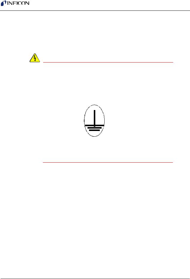
The IC/5 is connected to earth ground through a sealed three-core (three-conductor) power cable, which must be plugged into a socket outlet with a protective earth terminal. Extension cables must always have three conductors including a protective earth terminal.
WARNING - Risk Of Electric Shock
Never interrupt the protective earth circuit.
Any interruption of the protective earth circuit inside or outside the instrument, or disconnection of the protective earth terminal is likely to make the instrument dangerous.
This symbol indicates where the protective earth ground is connected inside the instrument. Never unscrew or loosen this connection.
IPN 074-237AE
1 - 4
IC/5 Operating Manual
1.2.4 Main Power Connection
WARNING - Risk Of Electric Shock
This instrument has line voltage present on the primary circuits whenever it is plugged into a main power source.
Never remove the covers from the instrument during normal operation.
There are no operator-serviceable items within this instrument.
Removal of the top or bottom covers must be done only by a technically qualified person.
In order to comply with accepted safety standards, this instrument must be installed into a rack system which contains a mains switch. This switch must break both sides of the line when it is open and it must not disconnect the safety ground.
IPN 074-237AE
1 - 5

IC/5 Operating Manual
1.3 How To Contact Customer Support
Worldwide support information regarding:
Technical Support, to contact an applications engineer with questions regarding INFICON products and applications, or
Sales and Customer Service, to contact the INFICON Sales office nearest you, or
Repair Service, to contact the INFICON Service Center nearest you,
is available at www.inficon.com.
If you are experiencing a problem with your instrument, please have the following information readily available:
the serial number for your instrument,
a description of your problem,
an explanation of any corrective action that you may have already attempted,
and the exact wording of any error messages that you may have received. To contact Customer Support, see Support at www.inficon.com.
1.3.1Returning Your Instrument
Do not return any component of your instrument to INFICON without first speaking with a Customer Support Representative. You must obtain a Return Material Authorization (RMA) number from the Customer Support Representative.
If you deliver a package to INFICON without an RMA number, your package will be held and you will be contacted. This will result in delays in servicing your instrument.
Prior to being given an RMA number, you may be required to complete a Declaration Of Contamination (DOC) form if your instrument has been exposed to process materials. DOC forms must be approved by INFICON before an RMA number is issued. INFICON may require that the instrument be sent to a designated decontamination facility, not to the factory. Failure to follow these procedures will delay the repair of your instrument.
IPN 074-237AE
1 - 6

IPN 074-237AE
IC/5 Operating Manual
1.4 IC/5 Specifications
1.4.1 Measurement
Crystal Frequency . . . . . . . . . . . . . . 6.0 MHz (new crystal) to 4.5 MHz
Internal Precision . . . . . . . . . . . . . . . ± 0.004657 Hz over 100 ms sample for fundamental and anharmonic frequencies
Thickness & Rate Resolution . . . . . . 0.00577 Å (new crystal);
0.01016 Å (crystal @ 4.5 MHz) over
100 ms sample for material density = 1.0, Z-ratio = 1.0
Thickness Accuracy . . . . . . . . . . . . . 0.5% typical, (dependent on process conditions, especially sensor location, material stress, temperature and density)
Frequency Accuracy. . . . . . . . . . . . . ± 2 ppm 0-50 °C Measurement Frequency . . . . . . . . . 10 Hz
Measurement Technique . . . . . . . . . ModeLock with Auto-Z
User Interface. . . . . . . . . . . . . . . . . . CRT and limited membrane keypad. All parameters accessible through computer communications. Multiple message areas for indication of states and detailed indication of abnormal and stop conditions.
1.4.2 Screens and Hierarchy
Navigation
1) Traditional. . . . . . . . . . . . . . . . Six soft keys
2) "Windows" influence. . . . . . . . X-tree like function with 4 levels of hide/show.
Structure . . . . . . . . . . . . . . . . . . . . . . Separate screens dedicated to 1) Materials, 2) Layers, 3) Logic, 4) Sensors, 5) Sources, 6) Utility,
7) Maintenance, 8) Communications,
9) Operation
1 - 7

IC/5 Operating Manual
1.4.3 Set-Up Parameters
# of Processes . . . . . . . . . . . . |
. . . . . 50 |
# of Layers . . . . . . . . . . . . . . . |
. . . . . 250 (total) |
# of Materials . . . . . . . . . . . . . |
. . . . . 24 |
Density . . . . . . . . . . . . . . . . . . |
. . . . . 0.100 to 99.99 gm/cc |
Z-ratio. . . . . . . . . . . . . . . . . . . |
. . . . . 0.100 to 15.000 or Automatic |
# of Sources . . . . . . . . . . . . . . |
. . . . . Any of 6 channels |
Co-deposition . . . . . . . . . . |
. . . . . 2 sources may operate concurrently |
Control Loop types . . . . . . . . . |
. . . . . (0,1,2) Non-PID, PI, PID |
PID Control Mode. . . . . . . . . . |
. . . . . Fast or Slow Source |
Process Gain . . . . . . . . . . . |
. . . . 0.01 to 100 Å/sec/%Power |
Primary Time Constant. . . . |
. . . . 0.010 to 200.0 seconds |
System Dead Time. . . . . . . |
. . . . 0.010 to 50.000 seconds |
Master Tooling Factor. . . . . . . . |
. . . . 10.0 to 400.0% |
Sensor Tooling Factor . . . . . . . |
. . . . 10.0 to 400.0% |
Sensor Weight . . . . . . . . . . . . . |
. . . . 1.0 to 400.0% |
Sensors . . . . . . . . . . . . . . . . . . |
. . . . 2 standard, 6 additional w/optional hardware |
CrystalSix Position Select |
. . . . . Material designation of position(s) |
Sensor Option . . . . . . . . . . . . . |
. . . . Enter 0 for "not used" |
|
Enter 1 for "stop if last to fail" |
|
Enter 2 for "time power if last to fail" |
|
Enter 3 for "stop if failed" |
|
Enter 4 for "time power if failed" |
Maximum Source Power . . . . . |
. . . . 0.0 to 99.9% |
Power Ramps. . . . . . . . . . . . . . |
. . . . 2 per material |
Power Level . . . . . . . . . . . . |
. . . . 0.0 to 99.9% |
Rise Time . . . . . . . . . . . . . . |
. . . . 00:00 to 99:59 min:sec |
Soak Time . . . . . . . . . . . . . |
. . . . 00:00 to 99:59 min:sec |
Auto Soak 2 Power . . . . . . . . . |
. . . . Yes/No |
Delay Option . . . . . . . . . . . . . . |
. . . . (0,1,2,3) None, Shutter Delay, |
|
Control Delay, Both |
Control Delay Time. . . . . . . . . . |
. . . . 00:00 to 99:59 |
1 - 8
IPN 074-237AE

IPN 074-237AE
IC/5 Operating Manual
Feed Ramps. . . . . . . . . . . . . . . . . . . 1 per material Feed Power . . . . . . . . . . . . . . . . 0.0 to 99.9%
Feed Ramp Time . . . . . . . . . . . . 00:00 to 99:59 min:sec Feed Time. . . . . . . . . . . . . . . . . . 00:00 to 99:59 min:sec
Idle Ramps . . . . . . . . . . . . . . . . . . . . 1 per material Idle Power. . . . . . . . . . . . . . . . . . 0.0 to 99.9%
Idle Ramp Time . . . . . . . . . . . . . 00:00 to 99:59 min:sec Aggregate Rate . . . . . . . . . . . . . . . . 0.0 to 999.9 Å/sec Aggregate Multiplier . . . . . . . . . . . . . Yes/No
Final Thickness . . . . . . . . . . . . . . . . 0.0 to 999.9 kÅ Thickness Limit. . . . . . . . . . . . . . . . . 0.0 to 999.9 kÅ
Time Limit . . . . . . . . . . . . . . . . . . . . . 00:00 to 99:59 min:sec Co-deposition
Cal Thick. . . . . . . . . . . . . . . . . . . uncal, 0.000 to 99.99kÅ Ratio Control. . . . . . . . . . . . . . . . 0 to 99%
RateWatcher® . . . . . . . . . . . . . . . . . Sample and Hold Feature RateWatch Time . . . . . . . . . . . . . 00:00 to 99:59 min:sec RateWatch . . . . . . . . . . . . . . . . . Accuracy 1 to 99%
Rate Ramps . . . . . . . . . . . . . . . . . . . 2 per layer New Rate . . . . . . . . . . . . . . . . . . 0 to 999 Å/sec Start Ramp . . . . . . . . . . . . . . . . . 0 to 999.9 kÅ
Ramp Time . . . . . . . . . . . . . . . . . 00:00 to 99:59 min:sec Crucible Selection . . . . . . . . . . . . . . 1 to 64, each source
1 - 9

IC/5 Operating Manual
1.4.4 Display
Type/Color/Size . . . . . . . . . . . . . . . . |
CRT/ Amber/ 5" H x 9" W |
Format . . . . . . . . . . . . . . . . . . . . . . . |
23 kHz Horizontal Scan Rate |
Resolution . . . . . . . . . . . . . . . . . . . . |
750 W x 350 H Monochrome |
Vertical Scan Rate . . . . . . . . . . . . . . |
50/60 Hz automatically detected |
Thickness Display Range. . . . . . . . . |
0.000 to 999.9 kÅ |
Thickness Display Resolution . . . . . 1 Å |
|
Rate Display Range . . . . . . . . . . . . . |
0.0 to 99.9 Å/sec; 100 to 999 Å/sec |
Rate Display Resolution. . . . . . . . . . |
0.1 Å for 0 to 99.9 Å/sec |
|
1 Å for 100 to 999 Å/sec |
Power Display Range. . . . . . . . . . . . |
0.0 to 99.9% |
Graphic Display Functions . . . . . . . . |
Rate Deviation at ± 10 or ± 20 Å/sec or Power |
|
at 0 to 100% |
Display Data Update Rate . . . . . . . . |
1 Hz |
IPN 074-237AE
1 - 10

|
|
IC/5 Operating Manual |
|
|
|
1.4.5 Source / Recorder Outputs |
|
|
|
Quantity . . . . . . . . . . . . . . . . . . . . . . |
6 BNC |
|
Configuration . . . . . . . . . . . . . . . . . . |
User programmable for recorder |
|
|
or source control. |
Function Ranges
Source Control . . . . . . . . . . . . . . 0 to 10 V, 0 to -10 V, 0 to 5 V, 0 to -5 V, 0 to 2.5 V, 0 to -2.5 V
Recorder Output . . . . . . . . . . . . . 0 to 10 V
Current rating . . . . . . . . . . . . . . . . . . 20 mA per channel Resolution . . . . . . . . . . . . . . . . . . . . 15 bits over full range (10 V)
Update Rate . . . . . . . . . . . . . . . . . . . 10 Hz, maximum, (dependent on source characteristics).
Recorder Output Functions . . . . . . . Aggregate Rate or Thickness or Rate Deviation; Individual Sensor Rate, Thickness or Rate Deviation; or Source Power.
Recorder Output Ranges
Rate . . . . . . . . . . . . . . . . . . . . . . 0 to 100 Å/sec, 0 to 1000 Å/sec Thickness . . . . . . . . . . . . . . . . . . 0 to 100 Å, 0 to 1000 Å
Rate Deviation . . . . . . . . . . . . . . Desired rate ± 50 Å/sec Accuracy. . . . . . . . . . . . . . . . . . . . . . ± 3% full scale
Zero Adjust . . . . . . . . . . . . . . . . . . . . Individual potentiometer
IPN 074-237AE
1 - 11

IC/5 Operating Manual
1.4.6 Logic Processing
Type . . . . . . . . . . . . . . . . . . . . . . . . . If/Then statements
Logical Functions . . . . . . . . . . . . . . . And; Or; Not; Parentheses; ON
Depth . . . . . . . . . . . . . . . . . . . . . . . . 5 "If" conditions and 5 "Then" results/actions per statement
# of Statements . . . . . . . . . . . . . . . . 100 If/Then
Selectable events . . . . . . . . . . . . . . . Deposition monitor events, states, external inputs, relays, timers, and counters.
Hierarchy . . . . . . . . . . . . . . . . . . . . . Statements evaluated in numerical order at 10 Hz any time the unit is on.
Partitioning . . . . . . . . . . . . . . . . . . . . None
Initialization . . . . . . . . . . . . . . . . . . . All outputs transition to their normal states as early as possible during power-on initialization sequence.
1.4.7 Relays / Inputs
Relays . . . . . . . . . . . . . . . . . . . . . . . SPST 2.5 A relays rated @ 30 V(dc) or 30 V(ac) RMS or 42 V(peak) maximum; (8 standard, up to 16 optional with 2
additional I/O cards); D sub connector; relays are normally open in the power off state, but may be programmed to normally open or normally closed during operation.
Relay Ratings. . . . . . . . . . . . . . . . . . 100 VA inductive; 2.5A maximum.
# of TTL Compatible Outputs . . . . . . 14 with optional I/O card. Internally pulled up to 5 V(dc). May be pulled up externally to 24 V(dc) through 2.4k resistor.
minimum high level 0.5mA load @3.75 V maximum low level 10mA load @1.1 V
Inputs (TTL Compatible). . . . . . . . . . (14 standard, 14 additional optional) Input Levels
maximum high . . . . . . . . . . . . . . 24 V minimum high . . . . . . . . . . . . . . . 2.5 V maximum low . . . . . . . . . . . . . . . 1.1 V Scan/Update Rate . . . . . . . . . . . . . . 10 Hz
1 - 12
IPN 074-237AE

IPN 074-237AE
IC/5 Operating Manual
1.4.8 Remote Communications
RS232C Serial Port . . . . . . . . . . . . . Standard; INFICON protocol Baud Rates. . . . . . . . . . . . . . . . . . . . 19,200; 9,600; 4,800; 2,400 IEEE488 Parallel Port. . . . . . . . . . . . Optional
IEEE Service Requests . . . . . . . . . . Supported with RQS and MAV status bits
1.4.9 Accessories
Manual Power . . . . . . . . . . . . . . . . . Front panel Control Connection
Function . . . . . . . . . . . . . . . . . . . . . . Handheld, increase/decrease/stop
Floppy (Optional) . . . . . . . . . . . . . . . 3.5', 1.44 MByte for process and datalog storage
Connector Kit . . . . . . . . . . . . . . . . . . Connectors for inputs and relays Operating Manual. . . . . . . . . . . . . . . 3-ring binder type
1.4.10 Power
Power . . . . . . . . . . . . . . . . . . . . . . . . 100 +10%, -15% V(ac) 50/60 Hz 120 +10%, -10% V(ac) 50/60 Hz 230 +10%, -10% V(ac) 50/60 Hz 240 +10%, -15% V(ac) 50/60 Hz
Maximum apparent power . . . . . . . . 300 VA
Fuse . . . . . . . . . . . . . . . . . . . . . . . . . 100 V(ac), 120 V(ac) use 4 Amp IEC 127 approved type T
230 V(ac), 240 V(ac) use 2 Amp IEC 127 approved type T
1 - 13

IC/5 Operating Manual
1.4.11 Operating Environment
Usage. . . . . . . . . . . . . . . . . . . . . . . . Indoor only
Temperature . . . . . . . . . . . . . . . . . . . 0 to 50 °C (32-122 °F)
Humidity . . . . . . . . . . . . . . . . . . . . . . Up to 85%RH, non-condensing
Altitude . . . . . . . . . . . . . . . . . . . . . . . Up to 2000 meters
Installation (Overvoltage) . . . . . . . . . Category II per IEC 664
Pollution Degree. . . . . . . . . . . . . . . . 1 per IEC 664
1.4.12 Storage Temperature
Storage Temperature . . . . . . . . . . . . -10 to 60 °C (14 to 140 °F)
1.4.13 Warm Up Period
Warm Up Period. . . . . . . . . . . . . . . . None required;
For maximum stability allow 5 minutes.
1.4.14 Size
Not including mounts or user connectors
5.25" H x 17.625" W x 18.5" D
(133.4 mm H x 447.7 mm W x 470 mm D) Including mounts, but no user connectors
5.25" H x 18.85" W x 18.5" D
(133.4 mm H x 478.8 mm W x 470 mm D)
1.4.15 Connector Clearance Requirements
Front. . . . . . . . . . . . . . . . . . . . . . . . . Less than 1.0" (25.4 mm)
Rear . . . . . . . . . . . . . . . . . . . . . . . . . Less than 4.0" (101.6 mm)
1.4.16 Weight
With all options. . . . . . . . . . . . . . . . . 13.2 kg / 29 lb
1.4.17 Cleaning
Use a mild, nonabrasive cleaner or detergent taking care to prevent cleaner from entering the unit.
1 - 14
IPN 074-237AE
Loading...