


IC-F11
INSTRUCTION MANUAL
VHF TRANSCEIVER
iF11/S
UHF TRANSCEIVER
iF21/S
This device complies with Part 15 of the FCC rules. Operation is subject to the following two conditions: (1) This device may not cause harmful interference, and (2) this
device must accept any interference received, including interference that may cause undesired operation.
WARNING
CAUTION
SAFETY TRAINING INFORMATION
Your Icom radio generates RF electromagnetic
energy during transmit mode. This radio is designed for and classified as “Occupational Use
Only”, meaning it must be used only during the
course of employment by individuals aware of the
hazards, and the ways to minimize such hazards.
This radio is NOT intended for use by the “General Population” in an uncontrolled environment.
This radio has been tested and complies with the FCC RF exposure limits for “Occupational Use Only.” In addition, your Icom radio
complies with the following Standards and Guidelines with regard to
RF energy and electromagnetic energy levels and evaluation of
such levels for exposure to humans:
• FCC OET Bulletin 65 Edition 97-01 Supplement C, Evaluating
Compliance with FCC Guidelines for Human Exposure to Radio
Frequency Electromagnetic Fields.
• American National Standards Institute (C95.1 – 1992), IEEE Standard for Safety Levels with Respect to Human Exposure to Radio
Frequency Electromagnetic Fields, 3 kHz to 300 GHz.
• American National Standards Institute (C95.3 – 1992), IEEE Recommended Practice for the Measurement of Potentially Hazardous
Electromagnetic Fields – RF and Microwave.
To ensure that your exposure to RF electromagnetic energy is within the FCC allowable limits for
occupational use, always adhere to the following
guidelines:
• DO NOT operate the radio without a proper antenna attached, as
this may damage the radio and may also cause you to exceed FCC
RF exposure limits. A proper antenna is the antenna supplied with
i

this radio by the manufacturer or an antenna specifically authorized
by the manufacturer for use with this radio.
“
• DO NOT transmit for more than 50% of total radio use time (
duty cycle”). Transmitting more than 50% of the time can cause
FCC RF exposure compliance requirements to be exceeded. The
radio is transmitting when the “TX indicator” lights red. You can
cause the radio to transmit by pressing the “PTT” switch.
• ALWAYS use Icom authorized accessories (antennas, batteries,
belt clips, speaker/mics, etc). Use of unauthorized accessories can
cause the FCC RF exposure compliance requirements to be exceeded.
• ALWAYS keep the antenna at least 2.5 cm (1 inch) away from the
body when transmitting and only use the Icom belt-clips, listed in p. 22,
when attaching the radio to your belt, etc., to ensure FCC RF exposure compliance requirements are not exceeded. To provide the
recipients of your transmission the best sound quality, hold the antenna at least 5 cm (2 inches) from mouth, and slightly off to one
side.
The information listed above provides the user with the information
needed to make him or her aware of RF exposure, and what to do to
assure that this radio operates within the FCC RF exposure limits of this
radio.
50%
Electromagnetic Interference/Compatibility
During transmissions, your Icom radio generates RF energy that
can possibly cause interference with other devices or systems. To
avoid such interference, turn off the radio in areas where signs are
posted to do so. DO NOT operate the transmitter in areas that are
sensitive to electromagnetic radiation such as hospitals, aircraft,
and blasting sites.
ii

FOREWORD
Thank you for purchasing the IC-F11/S, F21/S FM transceiver.
READ ALL INSTRUCTIONS carefully and completely before using
the transceiver.
SAVE THIS INSTRUCTION MANUAL–This instruction manual
contains important operating instructions for the transceiver.
IMPORTANT
R CAUTION! NEVER hold the transceiver so that the antenna is
very close to, or touching exposed parts of the body, especially the
face or eyes, while transmitting. The transceiver will perform best if
the microphone is 2 to 4 in. (5 to 10 cm) away from the lips and the
transceiver is vertical.
R CAUTION! NEVER operate the transceiver with a headset or
other audio accessories at high volume levels.
R CAUTION! NEVER short the terminals of the battery pack.
DO NOT push the PTT when not actually desiring to transmit.
AVOID using or placing the transceiver in direct sunlight or in areas
with temperatures below +14°F (–10°C) or above +122°F (+50°C).
DO NOT modify the transceiver for any reason.
KEEP the transceiver from the heavy rain, and Never immerse it in
the water. The transceiver construction is water resistant, not
water proof.
The use of non-Icom battery packs/chargers may impair transceiver
performance and invalidate the warranty.
FCC caution: Changes or modifications to this transceiver, not
expressly approved by Icom Inc., could void your authority to operate this transceiver under FCC regulations.
iii

TABLE OF CONTENTS
SAFETY TRAINING INFORMATION . . . . . . . . . . . . . . . . . . . . . . .i-ii
FOREWORD . . . . . . . . . . . . . . . . . . . . . . . . . . . . . . . . . . . . . . . . . .iii
IMPORTANT . . . . . . . . . . . . . . . . . . . . . . . . . . . . . . . . . . . . . . . . . .iii
TABLE OF CONTENTS . . . . . . . . . . . . . . . . . . . . . . . . . . . . . . . . .iv
1 PANEL DESCRIPTION . . . . . . . . . . . . . . . . . . . . . . . . . . . . . .1–3
‘ Switches, controls, keys and connectors . . . . . . . . . . . . . . .1–2
‘ LED indicator . . . . . . . . . . . . . . . . . . . . . . . . . . . . . . . . . . . . . .3
2 ACCESSORIES . . . . . . . . . . . . . . . . . . . . . . . . . . . . . . . . . . . . . .4
3 BATTERY PACKS . . . . . . . . . . . . . . . . . . . . . . . . . . . . . . . . .5–11
‘ Battery pack replacement . . . . . . . . . . . . . . . . . . . . . . . . . . . .5
‘ Battery cautions . . . . . . . . . . . . . . . . . . . . . . . . . . . . . . . . . . . .6
‘ Battery charging . . . . . . . . . . . . . . . . . . . . . . . . . . . . . . . . . .7-9
‘ Charging NOTE . . . . . . . . . . . . . . . . . . . . . . . . . . . . . . . . . .10
‘ Battery case (Option) . . . . . . . . . . . . . . . . . . . . . . . . . . . . . .11
44 PPRROOGGRRAAMMMMAABBLLEE FFUUNNCCTTIIOONNSS .. .. .. .. .. .. .. .. .. .. .. .. .. .. .. .. .. .. .. .. ..
‘ General . . . . . . . . . . . . . . . . . . . . . . . . . . . . . . . . . . . . . . . . .12
5 CONVENTIONAL OPERATION . . . . . . . . . . . . . . . . . . . . . .17-18
‘ Receiving and transmitting . . . . . . . . . . . . . . . . . . . . . . . . . .17
‘ Call procedure . . . . . . . . . . . . . . . . . . . . . . . . . . . . . . . . . . . .18
‘ Transmitting notes . . . . . . . . . . . . . . . . . . . . . . . . . . . . . . . . .18
6 CLONING . . . . . . . . . . . . . . . . . . . . . . . . . . . . . . . . . . . . . . . . . .20
7 OPTION . . . . . . . . . . . . . . . . . . . . . . . . . . . . . . . . . . . . . . . . .21-22
12-16
iv
1
y
u
Speaker
Mic
w
e
r
t
i
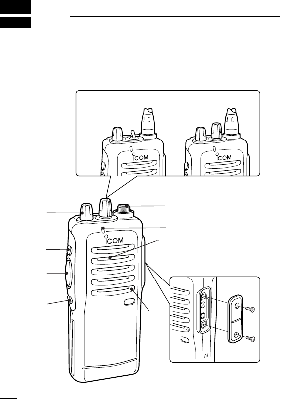
2CH version
CH1↔CH2
16CH version
CH1 to CH16
q
SP
MIC
‘‘
PANEL DESCRIPTION
Switches, controls, keys and
connectors
1

PANEL DESCRIPTION
q CHANNEL SELECTOR/SW [CH]
• 2CH version: Toggle the CH switch to select CH1 or CH2.
• 16CH version: Turn the selector knob to select the pro-
grammed operating channel.
w VOLUME CONTROL [OFF/VOL]
Turns power ON and adjusts the audio level.
e DEALER-PROGRAMMABLE KEY [Upper]
Can be programmed for one of several functions by your Icom
dealer.
r PTT SWITCH [PTT]
Push and hold to transmit; release to receive.
t DEALER-PROGRAMMABLE KEY [Lower]
Can be programmed for one of several functions by your Icom
dealer.
y ANTENNA CONNECTOR
Connects the supplied antenna.
u TX/RX INDICATOR LED (see p. 3)
• Lights red while transmitting.
• Lights green while receiving a signal, or squelch is open.
i [SP]/[MIC] JACK
Connects optional speaker-microphone.
NOTE: Above functions depend on pre-setting.
DD
Programmable key reference ([Red] depends on version.)
Red
Upper
Lower
*These functions are available when the optional Speaker/Mic. is con-
nected.
Mic Up*
Mic Down*
Mic A*
Mic B*
1
2
1
R R R R
R R
O O
O O
R R R R
R R
G
G G
R
PANEL DESCRIPTION
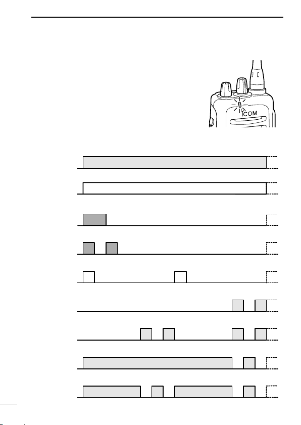
‘‘
LED indicator
The TX/RX indicator LED indicates several
more information as follows;
(Ref.; R=Red, G=Green, O=Orange)
• TX: Turns Red while transmitting a signal.
• RX: Turns Green while receiving a signal.
• Call LED (ON): When receiving a matched 2/5TONE.
• Call LED (Blink): When receiving a matched 2/5TONE.
• Fast/Slow scan: Blinks while Fast/Slow scan is activated.
•Low BATT1: You should charge the battery. (blinks slowly)
•Low BATT2: You must charge the battery. (blinks fast)
•TX low BATT1: Low BATT1 was detected during TX mode.
•TX low BATT2: Low BATT2 was detected during TX mode.
3
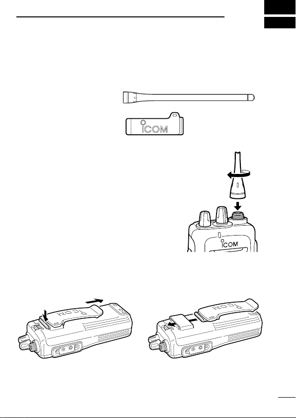
ACCESSORIES
q
w
‘‘
Accessory attachment
D Supplied accessories
The transceiver comes supplied with the following accessories.
q Flexible antenna
w Belt clip
D Antenna
The antenna screws onto the transceiver as
illustrated right.
D Belt clip
Attach the belt clip to the transceiver as illustrated below.
2
4
 Loading...