


LaserJet Pro M402
Table of contents
 Loading...
HP LaserJet Pro M402, LaserJet Pro M403, MFP M426, MFP M427 Troubleshooting Manual and Repair Manual
Troubleshooting Manual
www.hp.com/support/ljM402
www.hp.com/support/ljM403
www.hp.com/support/ljM426MFP
www.hp.com/support/ljM427MFP
For printer theory and troubleshooting
information, see the Repair Manual.
HEWLETT-PAC
KARD
2
1
M402d
M402n
M402dn
M402dw
M403n
M403d
M403dn
M403dw
2
1
M426dw
M426fdn
M426fdw
M427dw
M427fdn
M427fdw
LaserJet Pro MFP M426, M427
LaserJet Pro M402, M403


HP LaserJet Pro M402, M403 and
HP LaserJet Pro MFP M426, M427
Troubleshooting Manual

Copyright and License
Trademark Credits
© Copyright 2015 HP Development Company,
L.P.
Reproduction, adaptation, or translation
without prior written permission is prohibited,
except as allowed under the copyright laws.
The information contained herein is subject to
change without notice.
The only warranties for HP products and
services are set forth in the express warranty
statements accompanying such products and
services. Nothing herein should be construed
as constituting an additional warranty. HP shall
not be liable for technical or editorial errors or
omissions contained herein.
Edition 1, 9/2015
Microsoft®, Windows®, Windows® XP, and
Windows Vista® are U.S. registered trademarks
of Microsoft Corporation.

Conventions used in this guide
TIP: Helpful hints or shortcuts.
Reinstallation tip: Reinstallation helpful hints, shortcuts, or considerations.
NOTE: Information that explains a concept or how to complete a task.
IMPORTANT: Information that help the user to avoid potential printer error conditions.
CAUTION: Procedures that the user must follow to avoid losing data or damaging the printer.
WARNING! Procedures that the user must follow to avoid personal injury, catastrophic loss of data, or
extensive damage to the printer.
ENWW iii

iv Conventions used in this guide ENWW

For additional service and support information
HP service personnel, go to the Service Access Work Bench (SAW) at http://h41302.www4.hp.com/km/saw/
home.do.
Channel partners, go to HP Channel Services Network (CNS) at https://h30125.www3.hp.com/hpcsn.
At these locations, nd information on the following topics:
●
Install and congure
●
Printer specications
●
Up-to-date control panel message (CPMD) troubleshooting
●
Solutions for printer issues and emerging issues
●
Remove and replace part instructions and videos
●
Service advisories
●
Warranty and regulatory information
To access HP PartSurfer information from any mobile device, go to http://partsurfermobile.hp.com/ or scan
the Quick Response (QR) code below.
ENWW v

vi For additional service and support information ENWW

Table of contents
1 Theory of operation ....................................................................................................................................... 1
Related documentation and software ................................................................................................................... 2
Basic operation ...................................................................................................................................................... 3
Sequence of operation ........................................................................................................................ 4
Engine-control system .......................................................................................................................................... 5
DC controller ........................................................................................................................................ 6
Motor control ..................................................................................................................... 8
Fan control ........................................................................................................................ 8
Low-voltage power supply .................................................................................................................. 9
Over-current/over-voltage protection ........................................................................... 10
Safety ............................................................................................................ 10
Low-voltage power supply functions ........................................................... 10
High-voltage power supply ............................................................................................................... 11
High-voltage power supply circuits ................................................................................ 12
Fuser bias ........................................................................................................................ 12
Fuser control ..................................................................................................................................... 12
Fuser circuits ................................................................................................................... 13
Fuser control functions ................................................................................................... 14
Fuser heater protection .................................................................................................. 15
Engine laser/scanner system .............................................................................................................................. 16
Laser/scanner failure detection ........................................................................................................ 17
Safety ................................................................................................................................................ 17
Image-formation process ................................................................................................................. 18
Step 1: Primary charging ................................................................................................ 21
Step 2: Laser-beam exposure ......................................................................................... 22
Step 3: Development ...................................................................................................... 22
Step 4: Transfer ............................................................................................................... 23
Step 5: Separation ........................................................................................................... 24
Step 6: Fusing .................................................................................................................. 24
Step 7: Drum cleaning ..................................................................................................... 24
Toner cartridges ................................................................................................................................ 25
Design ............................................................................................................................. 25
ENWW vii

Memory chip .................................................................................................................... 27
Toner level and cartridge life detection .......................................................................... 27
Pickup, feed, and delivery system ....................................................................................................................... 27
Sensors and switches ........................................................................................................................ 29
Motors, clutches, and solenoids ........................................................................................................ 31
Jam detection/prevention ................................................................................................................. 31
Paper feeder (optional Tray 3) ............................................................................................................................. 35
Basic operation .................................................................................................................................. 35
Paper path ....................................................................................................................... 35
Paper feeder controller ................................................................................................... 35
Motor control .................................................................................................................. 36
Pickup and feed operation ................................................................................................................ 36
Electrical components, pickup and feed ......................................................................... 36
Other functions ............................................................................................................... 37
Jam detection .................................................................................................................. 38
2 Solve problems ............................................................................................................................................ 39
For additional service and support ..................................................................................................................... 40
Solve problems checklist ..................................................................................................................................... 41
Solve problems checklist ................................................................................................................... 41
Print the menu map ........................................................................................................ 42
Print a conguration page .............................................................................................. 42
Print the service page (includes the event log) .............................................................. 43
Print the demo page ....................................................................................................... 43
Troubleshooting process ..................................................................................................................................... 44
Determine the problem source ......................................................................................................... 44
Pre-troubleshooting checklist ........................................................................................ 44
Determine the problem source ....................................................................................... 46
Power subsystem .............................................................................................................................. 47
Power-on checks ............................................................................................................. 47
Control panel checks ......................................................................................................................... 47
Tools for troubleshooting .................................................................................................................................... 49
Component diagnostics .................................................................................................................... 49
LED diagnostics ............................................................................................................... 49
Network LEDs (network models only) ......................................................... 49
Control panel LEDs ....................................................................................... 49
Engine diagnostics .......................................................................................................... 50
Engine test .................................................................................................... 50
Diagrams ........................................................................................................................................... 51
Diagrams: Block diagrams .............................................................................................. 51
Cross-sectional view of printer .................................................................... 51
viii ENWW

Cross-sectional view of 550–sheet paper feeder ........................................ 52
Diagrams: Printed circuit assembly (PCA) connector locations ..................................... 53
Diagrams: DC controller connections ........................................................... 53
Paper feeder controller PCA ......................................................................... 54
Diagrams: External plug and port locations ................................................................... 54
Diagrams: Locations of major components ................................................................... 56
Major components (printer base) ................................................................. 56
Motor and fan ............................................................................................... 57
Rollers and pads (printer base) .................................................................... 58
PCAs (printer base) ....................................................................................... 59
Diagrams: Timing chart .................................................................................................. 60
Diagrams: Circuit diagrams ............................................................................................. 61
Advanced conguration with HP Embedded Web Server (EWS) and HP Device Toolbox
(Windows 7) ....................................................................................................................................... 62
Internal print-quality test pages ....................................................................................................... 64
Clean the paper path ....................................................................................................... 64
Clean the paper path (LCD control panel) .................................................... 64
Clean the paper path (touchscreen control panel) ...................................... 65
Print the conguration page ........................................................................................... 65
Print the conguration page from an LCD control panel ............................. 65
Print the conguration page from a touchscreen control panel ................. 65
Print-quality troubleshooting tools .................................................................................................. 66
Repetitive image defect ruler ......................................................................................... 66
Use a ruler to measure between repetitive defects ..................................... 66
Control panel menus ......................................................................................................................... 70
HP Web Services menu ................................................................................................... 70
Reports menu ................................................................................................................. 70
Quick Forms menu .......................................................................................................... 71
USB Flash Drive menu ..................................................................................................... 71
System Setup menu ........................................................................................................ 72
Service menu ................................................................................................................... 74
Network Setup menu ...................................................................................................... 77
Control panel message document (CPMD) ....................................................................................... 79
Control-panel message types ........................................................................................ 79
Control-panel messages and event log entries ............................................................. 79
30.XX Error Messages ................................................................................... 79
49.XX.YY Error Messages ............................................................................. 80
50.XX fuser errors ........................................................................................ 80
51.XX and 52 Laser/Scanner Errors ............................................................. 81
55.XXXX Error Messages .............................................................................. 82
57.XX Error Messages ................................................................................... 83
ENWW ix

58.XX Error Messages ................................................................................... 83
59.XX Error Messages ................................................................................... 84
79 Errors ....................................................................................................... 85
Alpha Error Messages ................................................................................... 85
Event-log messages .......................................................................................................................... 96
Print the event log .......................................................................................................... 96
Print the event log (LCD control panel) ........................................................ 96
Print the event log (touchscreen control panel) .......................................... 97
Show an event log ........................................................................................................... 97
Event-log messages ....................................................................................................... 97
Clear paper jams ................................................................................................................................................ 101
Clear paper jams (M402, M403) ...................................................................................................... 101
Introduction .................................................................................................................. 101
Experiencing frequent or recurring paper jams? ......................................................... 101
Jam locations ................................................................................................................ 102
Clear paper jams in Tray 1 ............................................................................................ 103
Clear paper jams in Tray 2 ............................................................................................ 104
Clear paper jams in optional Tray 3 .............................................................................. 108
Clear paper jams in the fuser ........................................................................................ 111
Clear paper jams in the output bin ............................................................................... 115
Clear paper jams in the duplexer .................................................................................. 117
Clear paper jams (M426, M427) ...................................................................................................... 119
Introduction .................................................................................................................. 119
Experiencing frequent or recurring paper jams? ......................................................... 119
Jam locations ................................................................................................................ 120
Clear paper jams in the document feeder .................................................................... 122
Clear paper jams in Tray 1 ............................................................................................ 125
Clear paper jams in Tray 2 ............................................................................................ 126
Clear paper jams in optional Tray 3 .............................................................................. 130
Clear paper jams in the fuser ........................................................................................ 134
Clear paper jams in the output bin ............................................................................... 137
Clear paper jams in the duplexer .................................................................................. 140
Solve paper-handling problems ........................................................................................................................ 142
The printer picks up multiple sheets of paper ................................................................................ 142
The printer does not pick up paper ................................................................................................. 142
Solve image quality problems ........................................................................................................................... 143
Print quality examples .................................................................................................................... 143
Clean the printer ................................................................................................................................................ 150
Clean the pickup and separation rollers ......................................................................................... 150
Clean the paper path ....................................................................................................................... 150
Clean the paper path (LCD control panel) ..................................................................... 150
x ENWW

Clean the paper path (touchscreen control panel) ....................................................... 150
Clean the touchscreen ..................................................................................................................... 150
Solve performance problems ............................................................................................................................ 152
Factors aecting print performance ............................................................................................... 152
Print speeds .................................................................................................................. 152
The product does not print or it prints slowly ................................................................................ 153
The product does not print ........................................................................................... 153
The product prints slowly ............................................................................................. 154
Solve connectivity problems ............................................................................................................................. 155
Solve direct-connect problems ....................................................................................................... 155
Solve network problems ................................................................................................................. 155
Poor physical connection .............................................................................................. 155
The computer is using the incorrect IP address for the product .................................. 155
The computer is unable to communicate with the product ......................................... 156
The product is using incorrect link and duplex settings for the network .................... 156
New software programs might be causing compatibility problems ........................... 156
The computer or workstation might be set up incorrectly .......................................... 156
The product is disabled, or other network settings are incorrect ............................... 156
Solve wireless network problems ................................................................................................... 157
Wireless connectivity checklist ..................................................................................... 157
The control panel displays the message: The wireless feature on this product has
been turned o ............................................................................................................. 157
The product does not print after the wireless conguration completes ..................... 158
The product does not print, and the computer has a third-party rewall installed ... 158
The wireless connection does not work after moving the wireless router or
product .......................................................................................................................... 158
Cannot connect more computers to the wireless product ........................................... 158
The wireless product loses communication when connected to a VPN ...................... 159
The network does not appear in the wireless networks list ........................................ 159
The wireless network is not functioning ...................................................................... 159
Service mode functions ..................................................................................................................................... 160
Service menu ................................................................................................................................... 160
Service menu settings .................................................................................................. 160
Restore the factory-set defaults .................................................................................. 160
Restore the factory-set defaults (LCD control panel) ................................ 160
Restore the factory-set defaults (touchscreen control panel) .................. 161
Secondary service menu ................................................................................................................. 161
Open the secondary service menu ............................................................................... 161
Open the secondary service menu (LCD control panel) ............................. 161
Open the secondary service menu (touchscreen control panel) ............... 161
Secondary service menu structure ............................................................................... 162
ENWW xi

Developer's menu ............................................................................................................................ 162
Open the Developer's menu (LCD control panel) ......................................................... 162
Open the Developer's menu (touchscreen control panel) ........................................... 163
Product resets ................................................................................................................................. 164
NVRAM initialization ..................................................................................................... 164
Solve fax problems (fax models only) ............................................................................................................... 165
Introduction ..................................................................................................................................... 165
Fax troubleshooting checklist ......................................................................................................... 165
Solve general fax problems ............................................................................................................ 166
Faxes are sending slowly .............................................................................................. 166
Fax quality is poor ......................................................................................................... 167
Fax cuts o or prints on two pages .............................................................................. 168
Solve email problems (M426, M427 printes) .................................................................................................... 169
Cannot connect to the email server ................................................................................................ 169
Validate the SMTP gateway (Windows) .......................................................................................... 169
Validate the LDAP gateway (Windows) ........................................................................................... 169
Manually update the rmware .......................................................................................................................... 170
Manually update the rmware (LCD control panel) ........................................................................ 170
Manually update the rmware (touchscreen control panel) .......................................................... 170
Appendix A Printer specications .................................................................................................................. 171
Printer dimensions M426 and M427 ................................................................................................................. 172
Printer dimensions M402 and M403 ................................................................................................................. 174
Printer space requirements ............................................................................................................................... 176
Power consumption, electrical specications, and acoustic emissions ........................................................... 176
Operating-environment range .......................................................................................................................... 176
Certicate of Volatility ....................................................................................................................................... 177
Index ........................................................................................................................................................... 181
xii ENWW

List of tables
Table 1-1 Sequence of operation .......................................................................................................................................... 4
Table 1-2 Motors ................................................................................................................................................................... 8
Table 1-3 Fans ....................................................................................................................................................................... 8
Table 1-4 List of DC voltages ................................................................................................................................................ 9
Table 1-5 Low-voltage power supply functions ................................................................................................................. 10
Table 1-6 High-voltage power supply circuits .................................................................................................................... 12
Table 1-7 Fuser components .............................................................................................................................................. 13
Table 1-8 Fuser control functions ...................................................................................................................................... 14
Table 1-9 Sensors ............................................................................................................................................................... 20
Table 1-10 Image formation process ................................................................................................................................. 21
Table 1-11 Toner cartridge functions ................................................................................................................................. 26
Table 1-12 Pickup, feed, and delivery system functions ................................................................................................... 28
Table 1-13 Photo sensors and switches ............................................................................................................................. 30
Table 1-14 Motors, solenoids, and clutches ....................................................................................................................... 31
Table 1-15 Jams that the printer detects ........................................................................................................................... 32
Table 1-16 Electrical component list, paper feeder ........................................................................................................... 36
Table 1-17 Motors, paper feeder ........................................................................................................................................ 36
Table 1-18 Electrical components, pickup and feed .......................................................................................................... 37
Table 1-19 Other functions, paper feeder .......................................................................................................................... 37
Table 2-1 DC controller connectors .................................................................................................................................... 53
Table 2-2 Paper feeder controller PCA connectors ............................................................................................................ 54
Table 2-3 M402, M403 external plugs and ports ............................................................................................................... 54
Table 2-4 M426, M427 external plugs and ports ............................................................................................................... 55
Table 2-5 Major components (printer base) ....................................................................................................................... 56
Table 2-6 Motor and fan (printer base) .............................................................................................................................. 57
Table 2-7 Rollers and pads (printer base) .......................................................................................................................... 58
Table 2-8 Main PCAs (printer base) ..................................................................................................................................... 59
Table 2-9 Repetitive defects ............................................................................................................................................... 66
Table 2-10 Event-log messages (X=0: black cartridge) ..................................................................................................... 97
Table 2-11 Fax event log codes ........................................................................................................................................ 100
Table 2-12 Print quality examples ................................................................................................................................... 143
Table 2-13 Secondary Service menu ................................................................................................................................ 162
ENWW xiii

Table A-1 Operating-environment specications ............................................................................................................ 176
xiv ENWW

List of gures
Figure 1-1 Relationship between the main printer systems ............................................................................................... 3
Figure 1-2 Engine-control system ........................................................................................................................................ 5
Figure 1-3 DC controller block diagram ................................................................................................................................ 6
Figure 1-4 Low-voltage power-supply circuit ...................................................................................................................... 9
Figure 1-5 High-voltage power supply circuits .................................................................................................................. 12
Figure 1-6 Fuser components ............................................................................................................................................ 13
Figure 1-7 Fuser control ..................................................................................................................................................... 14
Figure 1-8 Laser/scanner system ....................................................................................................................................... 16
Figure 1-9 Image-formation system .................................................................................................................................. 18
Figure 1-10 Fuser motor (M1) and image formation components .................................................................................... 19
Figure 1-11 Toner-level sensor .......................................................................................................................................... 20
Figure 1-12 Image-formation process ............................................................................................................................... 20
Figure 1-13 Primary charging ............................................................................................................................................. 21
Figure 1-14 Laser-beam exposure ..................................................................................................................................... 22
Figure 1-15 Development ................................................................................................................................................... 22
Figure 1-16 Primary transfer .............................................................................................................................................. 23
Figure 1-17 Separation ....................................................................................................................................................... 24
Figure 1-18 Fusing .............................................................................................................................................................. 24
Figure 1-19 Drum cleaning ................................................................................................................................................. 25
Figure 1-20 Toner cartridge system ................................................................................................................................... 26
Figure 1-21 Pickup, feed, and delivery system .................................................................................................................. 28
Figure 1-22 Sensors and switches for the pickup, feed, and delivery system .................................................................. 29
Figure 1-23 Motors, solenoids, and clutches ..................................................................................................................... 31
Figure 1-24 Jam detection sensors .................................................................................................................................... 32
Figure 1-25 Optional Tray 3 paper path ............................................................................................................................. 35
Figure 1-26 Paper feeder controller ................................................................................................................................... 36
Figure 1-27 Electrical components, pickup and feed ......................................................................................................... 37
Figure 2-1 Cross-sectional view of printer ......................................................................................................................... 51
Figure 2-2 Cross-sectional view of 500–sheet paper feeder ............................................................................................ 52
Figure 2-3 DC controller PCA connectors ........................................................................................................................... 53
Figure 2-4 Paper feeder controller PCA connectors ........................................................................................................... 54
Figure 2-5 M402, M403 external plugs and ports locations .............................................................................................. 54
ENWW xv

Figure 2-6 M426, M427 external plug and port locations ................................................................................................. 55
Figure 2-7 Major components (printer base) ..................................................................................................................... 56
Figure 2-8 Motor and fan .................................................................................................................................................... 57
Figure 2-9 Rollers and pads (printer base) ......................................................................................................................... 58
Figure 2-10 Main PCAs (printer base) ................................................................................................................................. 59
Figure 2-11 General timing chart ....................................................................................................................................... 60
Figure 2-12 General circuit diagram (printer base) ............................................................................................................ 61
Figure 2-13 Examples of repetitive defects ....................................................................................................................... 67
Figure 2-14 Place the ruler on the page ............................................................................................................................. 68
Figure 2-15 Locate the next repetitive defect ................................................................................................................... 68
Figure 2-16 Determine the defective assembly ................................................................................................................. 69
Figure A-1 Dimensions for the M426 and M427 models ................................................................................................. 172
Figure A-2 Dimensions for the optional 550-sheet tray .................................................................................................. 172
Figure A-3 Dimensions for the printer with the optional 550-sheet tray ....................................................................... 173
Figure A-4 Dimensions for the M402 and M403 models ................................................................................................. 174
Figure A-5 Dimensions for the optional 550-sheet tray .................................................................................................. 174
Figure A-6 Dimensions for the printer with the optional 550-sheet tray ....................................................................... 175
Figure A-7 Certicate of Volatility M402/M403 (1 of 2) ................................................................................................... 177
Figure A-8 Certicate of Volatility M402/M403 (2 of 2) ................................................................................................... 178
Figure A-9 Certicate of Volatility M426/M427 (1 of 2) ................................................................................................... 179
Figure A-10 Certicate of Volatility M426/M427 (2 of 2) ................................................................................................ 180
xvi ENWW

1 Theory of operation
●
Related documentation and software
●
Basic operation
●
Engine-control system
●
Engine laser/scanner system
●
Pickup, feed, and delivery system
●
Paper feeder (optional Tray 3)
ENWW 1

Related documentation and software
HP service personnel, go to the Service Access Work Bench (SAW) at http://h41302.www4.hp.com/km/saw/
home.do.
Channel partners, go to HP Channel Services Network (CSN) at https://h30125.www3.hp.com/hpcsn.
2 Chapter 1 Theory of operation ENWW
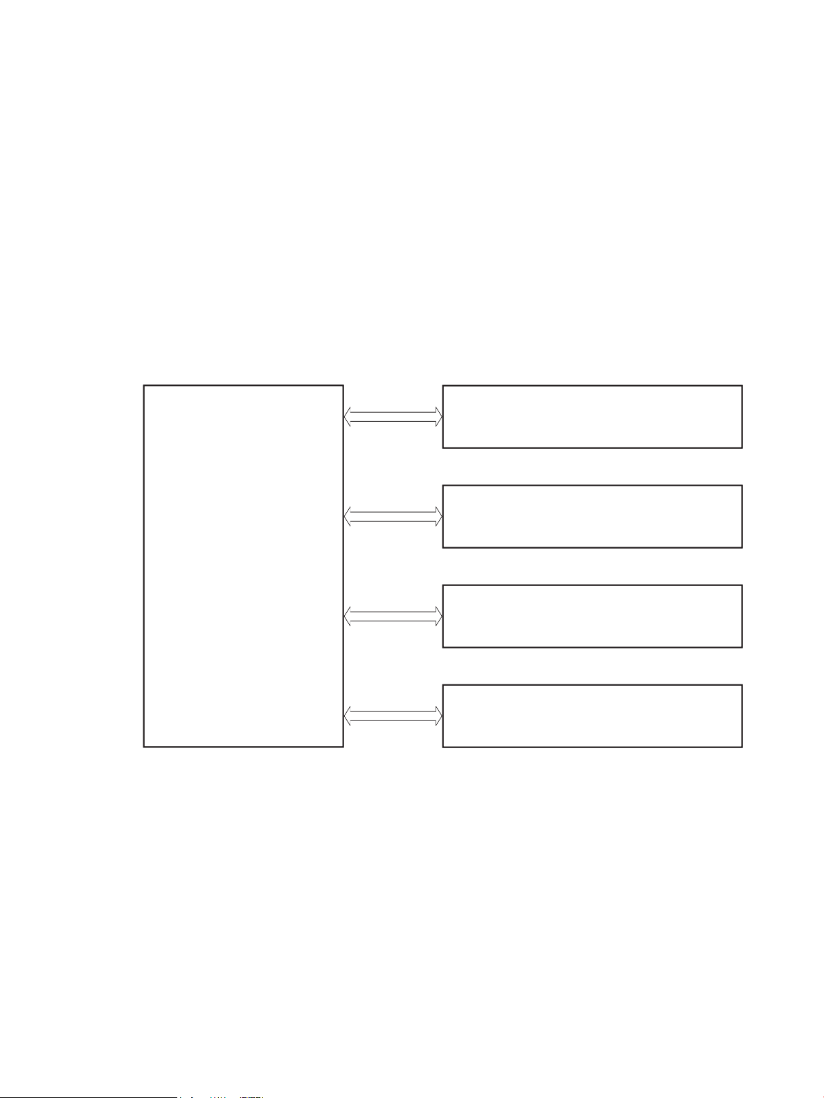
Basic operation
Engine-control system
Laser scanner system
Image-formation system
Pickup, feed, and delivery system
Accessory
Engine-control system
Laser scanner system
Image-formation system
Pickup, feed, and delivery system
Accessor
y
The printer routes all high-level processes through the formatter, which stores font information, processes
the print image, and communicates with the host computer.
The basic printer operation comprises the following systems:
●
Engine-control system
●
Laser/scanner system
●
Image-formation system
●
Pickup, feed, and delivery system
●
Accessory (optional paper feeder)
Figure 1-1 Relationship between the main printer systems
ENWW Basic operation 3

Sequence of operation
The DC controller PCA controls the operating sequence, as described in the following table.
Table 1-1 Sequence of operation
Period Duration Description
Waiting From the time the power is turned on, the door is
closed, or when the printer exits Sleep mode until the
printer is ready for printing.
Standby From the end of the waiting sequence or the last
rotation until the formatter receives a print command,
or until the printer is turned o.
Initial rotation From the time the formatter receives a print command
until the paper enters the paper path.
Printing From the time the rst sheet of paper enters the paper
path until the last sheet passes through the fuser.
●
Heats the fuser lm in the fuser
●
Detects the toner cartridge
●
Rotates and stops each motor
●
Rotates and stops each fan
●
Cleans the transfer roller
●
Is in the Ready state
●
Enters Sleep mode if the formatter sends the
sleep command
●
Rotates and stops each fan
●
Rotates each motor
●
Rotates each fan
●
Activates the high-voltage power supply (highvoltage bias)
●
Prepares the laser/scanner unit
●
Warms the fuser to the correct temperature
●
Forms the image on the photosensitive drums
●
Transfers the toner to the paper
Last rotation From the time the last sheet of paper exits the fuser
until the motors stop rotating.
●
Fuses the toner image onto the paper
●
Stops each motor
●
Stops each fan
●
Stops the high-voltage power supply (highvoltage bias)
●
Stops the laser/scanner unit
●
Turns the fuser heater o
●
If another print command is received, the printer
enters the initial rotation period when the last
rotation is complete.
4 Chapter 1 Theory of operation ENWW
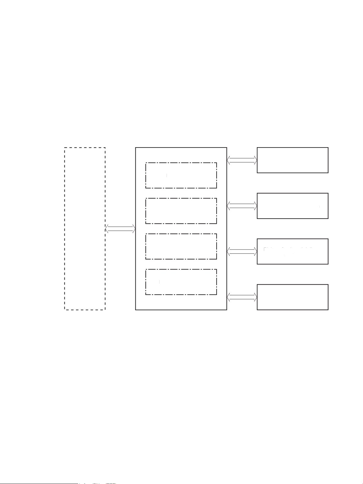
Engine-control system
Formatter
Engine-control system
DC controller
Low-voltage power supply
Laser scanner system
Image-formation system
Pickup, feed, and delivery
system
Accessory
High-voltage power supplies
Fuser power supply
Formatter
Engine-control system
DC controller
Low-voltage power suppl
y
Laser scanner system
Image-formation system
Pickup, feed, and delivery
sy
stem
Accessor
y
igh-voltage power supplies
Fuser power suppl
y
The engine-control system receives commands from the formatter and interacts with the other main systems
to coordinate all printer functions. The engine-control system consists of the following components:
●
DC controller
●
Low-voltage power supply
●
High-voltage power supplies
●
Fuser power supply
Figure 1-2 Engine-control system
ENWW Engine-control system 5
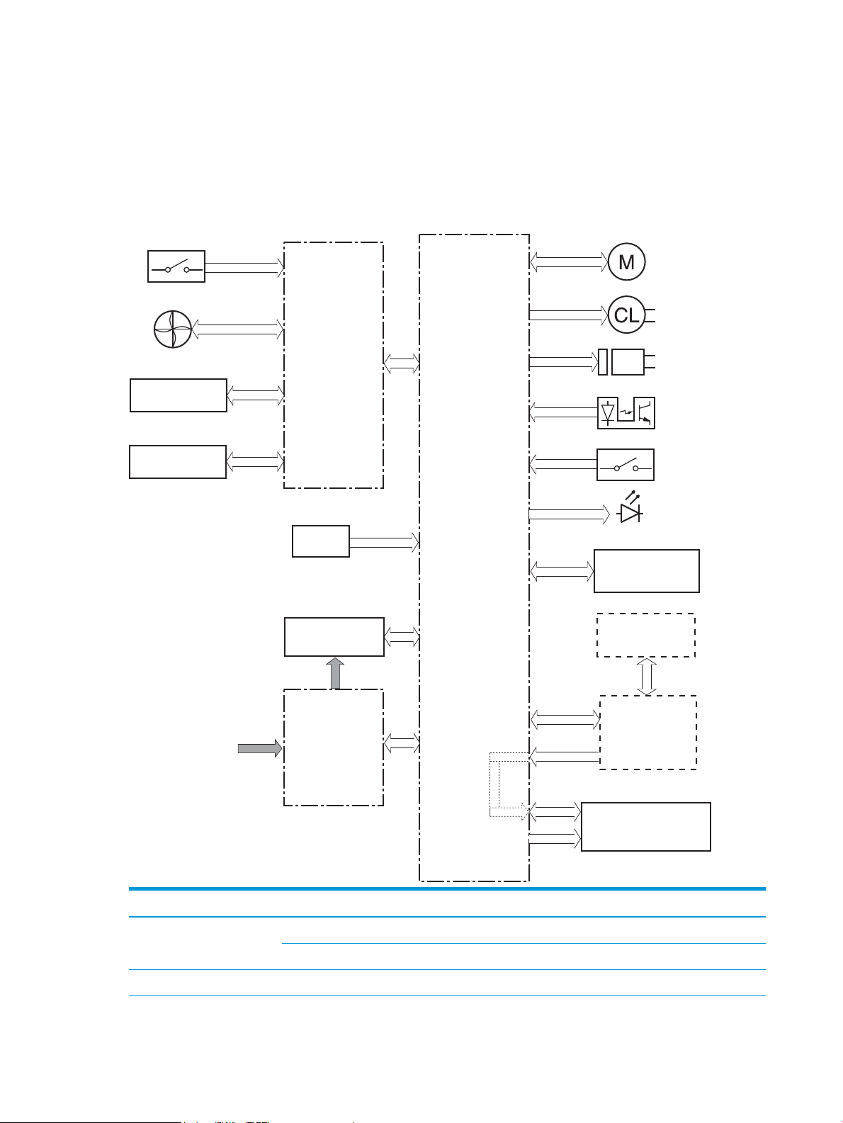
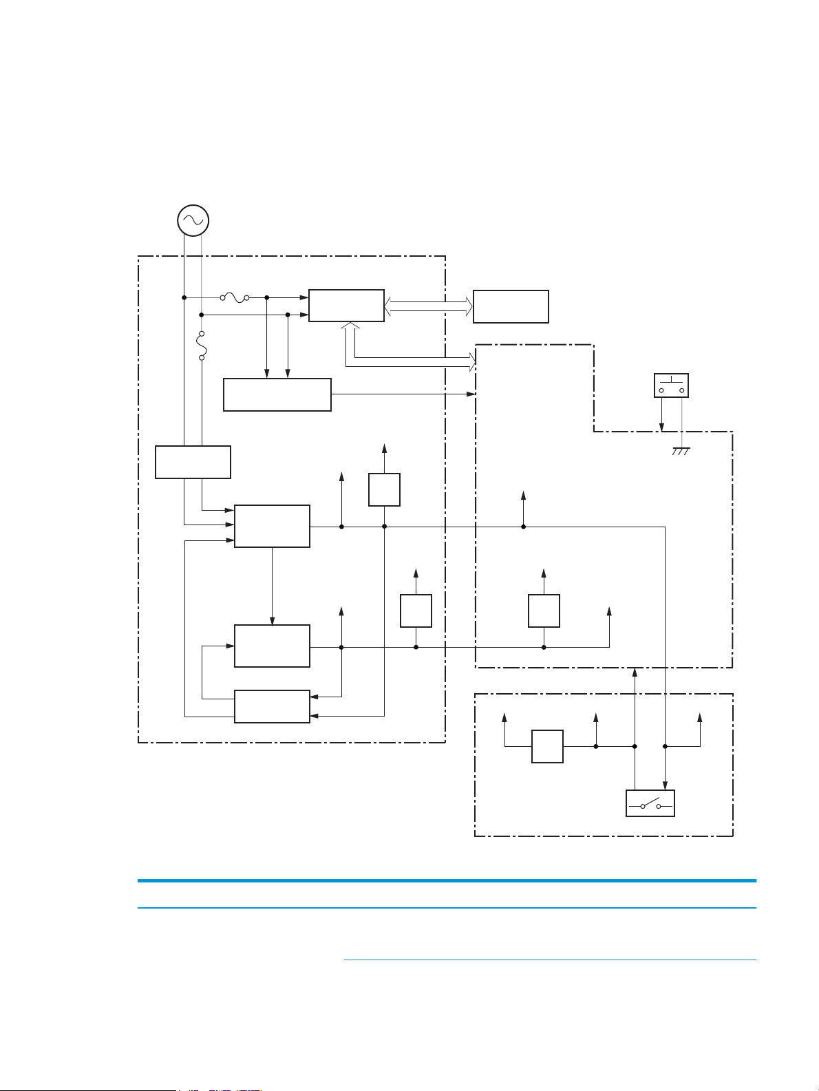
DC controller
Transfer roller
High-voltage
power supply
Fan
Cartridge
LED
Motor
Clutch
Solenoid
Switch
Photointerrupter
Formatter
Control panel
Accessory
Laser scanner ass’y
Fuser
AC input
Low-voltage
power supply
DC controller
Switch
Sensor
The DC controller controls the operation of the printer and its components. The DC controller starts the
printer operation when the printer power is turned on and the power supply sends DC voltage to the DC
controller. After the printer enters the standby period, the DC controller sends out various signals to operate
motors, solenoids, and other printer components based on the print command and image data that the host
computer sends.
Figure 1-3 DC controller block diagram
Component type Abbreviation Description
Motor M1 Fuse motor
M3 Scanner motor
Fan Fm1 Main fan
6 Chapter 1 Theory of operation ENWW

Component type Abbreviation Description
Solenoid SL1 Cassette pickup solenoid
SL2 MP tray pickup solenoid
SL3 Duplex switchback solenoid
Clutch CL1 Duplex re-pickup clutch
Switch SW1 Power switch
SW101 Cartridge door switch
Photointerrupter PS1a Media width sensor
PS2b Duplex feed sensor
PS1 Cassette media out sensor
PS2 Top sensor
PS3 MP tray media out sensor
PS4 Output bin media-full sensor
PS13 Fuser output sensor
Sensor TH1 Environment sensor
LED LED1 Power supply LED
1
Duplex models only.
ENWW Engine-control system 7

Motor control
The printer has two motors. The motors drive the components in the paper-feed and image-formation
systems.
The DC controller monitors the fuser motor and the scanner motor to determine if a motor has failed. It
noties the formatter when it encounters the following conditions:
●
●
Table 1-2 Motors
Abbreviation Name Purpose Failure detection
Startup failure: the motor does not reach a specied speed within a specied time from when the motor
starts.
Rotational failure: the rotational speed of the motor is not in the specied range for a specied time
after the motor reaches a specied speed.
Fan control
The printer has one fan for preventing the temperature from rising in the printer and for cooling the printed
pages.
The DC controller determines if there is a fan failure and noties the formatter if the fan locks for a specied
time from when the fan starts.
Table
M1 Fuser motor Drives the pressure roller and delivery roller;
the pressurization and release of the pressure
roller; and the engagement and
disengagement of the primary and secondary
transfer rollers
M3 Scanner motor Drives the scanner mirror Yes
1-3 Fans
Abbreviation Name Cooling area Type Speed
FM1 Main fan Inside of printer Intake Full
Yes
8 Chapter 1 Theory of operation ENWW
Low-voltage power supply
AC input
+24VA
FET
FET
+24VB
+24VC
+24VD
+24VBSNS
+24VA
FET
PWRSW
+3.3VA
FET
+3.3VC
+3.3VB
+3.3VA
+24VA
Low-voltage power supply
Rectifying
circuit
Protection
circuit
+24V
generation
circuit
Fuse
FU101
Fuse
FU102
+3.3V
generation
circuit
Fuser
Power switch
SW1
DC controller
High-voltage power supply
Interlock switch
SW101
Fuser control
circuit
FREQSNS_LVT
Frequency
detection circuit
The low-voltage power-supply (LVPS) circuit converts the AC power from the wall receptacle into the DC
voltage that the printer components use.
Figure 1-4 Low-voltage power-supply circuit
Table 1-4 List of DC voltages
DC power supply Description
+24V +24VA Constantly supplied
Becomes 4.5V during active OFF or inactive OFF
ENWW Engine-control system 9

Table 1-4 List of DC voltages (continued)
DC power supply Description
+3.3V +3.3VA Constantly supplied
Over-current/over-voltage protection
The low-voltage power supply has a protective function against overcurrent and overvoltage conditions to
prevent failures in the power supply circuit. If an overcurrent or overvoltage event occurs, the system
automatically cuts o the output voltage.
+24VB Stopped when cartridge door is opened. (SW101)
Stopped during active OFF or inactive OFF
+24VC Stopped when cartridge door is opened. (SW101)
Stopped during active OFF or inactive OFF
+24VD Constantly supplied
Stopped during active OFF or inactive OFF
+3.3VB Constantly supplied
Stopped during active OFF or inactive OFF
+3.3VC Constantly supplied
Stopped during inactive OFF
If the DC power is not being supplied from the low-voltage power supply, the protective function might have
activated. In this case, turn o the power switch, and then unplug the power cord. Do not plug in the power
cord or turn the power switch on again until the root cause is found.
In addition, two fuses in the low-voltage power supply protect against an overcurrent event. If an overcurrent
event occurs in the AC line, the fuse blows and cuts o the power distribution.
Safety
For personal safety, the printer interrupts +24VB and +24VC power when the cartridge door detection switch
is turned o. This stops DC power supply to the high-voltage power supply (HVPS).
The remote switch control circuit turns on or o the printer power so that the AC power ows even the power
switch is turned o. Unplug the printer power cord before disassembling the printer.
Low-voltage power supply functions
The printer has the following low-voltage power supply functions.
1-5 Low-voltage power supply functions
Table
Failure detective function Applied
Sleep mode NA
Power supply voltage detection NA
Automatic power OFF NA
Automatic power ON/OFF NA
10 Chapter 1 Theory of operation ENWW

Table 1-5 Low-voltage power supply functions (continued)
Failure detective function Applied
Active OFF Yes
Inactive OFF Yes
Network mode NA
Power switch illumination Yes
Low-voltage power supply failure detection Yes
Power save mode NA
High-voltage power supply
The DC controller controls the high-voltage power supply (HVPS) to generate biases. The high-voltage power
supply delivers the high-voltage biases to the following components used to transfer toner during the imageformation process:
●
Primary charging roller (in the toner cartridge)
●
Developing roller (in the toner cartridge)
●
Transfer roller
●
Pressure roller
ENWW Engine-control system 11
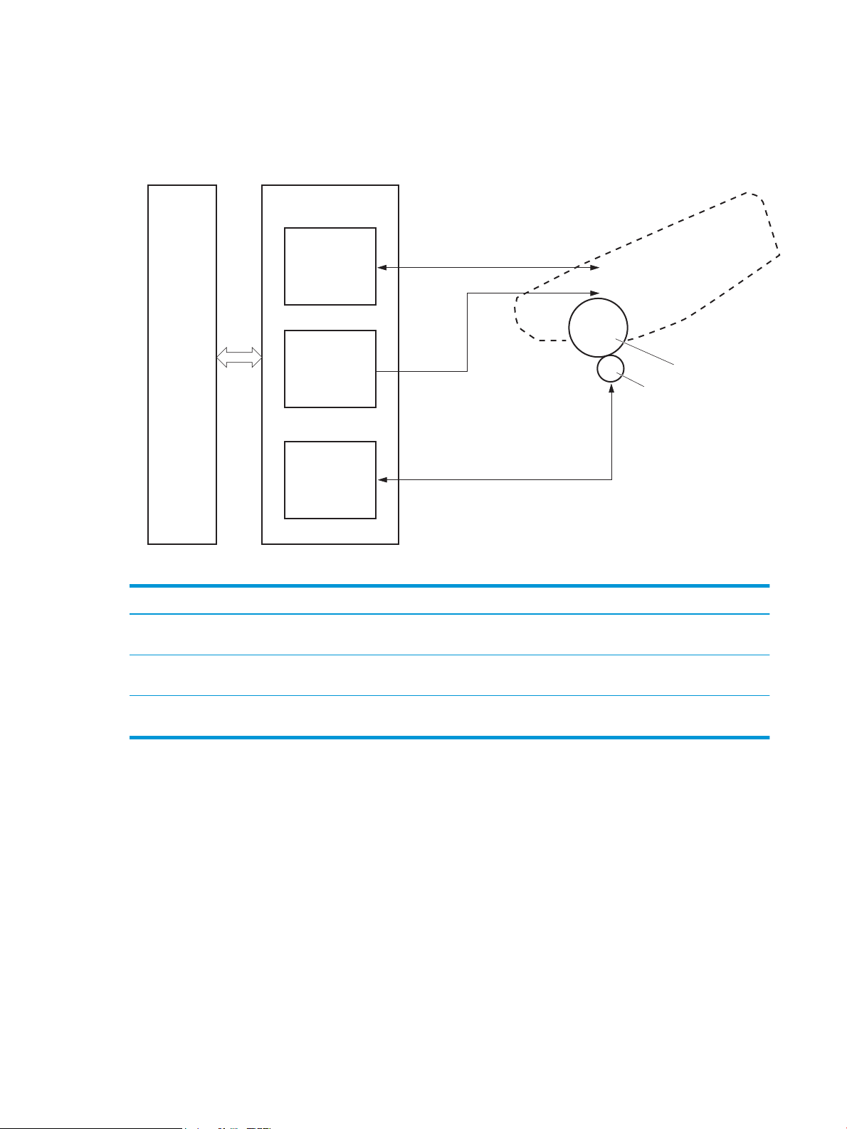
High-voltage power supply circuits
PRI
DEV
TR
DC controller
High-voltage power supply
To primary charge roller
To developing roller
Cartridge
Photosensitive drum
Transfer roller
Primary
charging bias
circuit
Developing
bias circuit
Transfer bias
circuit
The high-voltage power supply contains the following separate circuits.
Figure 1-5 High-voltage power supply circuits
Fuser bias
Fuser control
Table 1-6 High-voltage power supply circuits
Circuit Description
Primary-charging-bias generation The primary charging bias negatively charges the surface of the photosensitive drum to
prepare for image formation.
Developing-bias generation The developing bias adheres toner to an electrostatic latent image formed on the
photosensitive drums.
Transfer-bias generation The primary transfer bias transfers the toner from each photosensitive drum onto the
page.
The printer uses on-demand fusing. The fuser bias is DC positive for improved print quality. The fuser bias
circuit is located in the high-voltage power supply, HVPS (T).
The DC controller and components in the fuser perform the following functions related to fuser operation:
●
Control fuser temperature
●
Detect fuser failures
●
Prevent excessive temperature rise
12 Chapter 1 Theory of operation ENWW
Loading...