


 Loading...
LASERJET PRO 400 MFP
Repair Manual
M425

HP LaserJet Pro 400 MFP M425 Series
Repair Manual
Copyright and License
© 2012 Copyright Hewlett-Packard
Development Company, L.P.
Reproduction, adaptation, or translation without prior written permission is prohibited, except as allowed under the copyright laws.
The information contained herein is subject to change without notice.
The only warranties for HP products and services are set forth in the express warranty statements accompanying such products and services. Nothing herein should be construed as constituting an additional warranty. HP shall not be liable for technical or editorial errors or omissions contained herein.
Part number: CF286-90979
Edition 1, 4/2012
Trademark Credits
Microsoft®, Windows®, Windows® XP, and Windows Vista® are U.S. registered trademarks of Microsoft Corporation.

Conventions used in this guide

 TIP: Tips provide helpful hints or shortcuts.
 NOTE: Notes provide important information to explain a concept or to complete a task.
CAUTION: Cautions indicate procedures that you should follow to avoid losing data or damaging the product.
WARNING! Warnings alert you to specific procedures that you should follow to avoid personal injury, catastrophic loss of data, or extensive damage to the product.
ENWW |
iii |

Table of contents
1 Removal and replacement ................................................................................................ |
1 |
Removal and replacement strategy ............................................................................................. |
2 |
Electrostatic discharge ............................................................................................... |
2 |
Required tools ........................................................................................................... |
3 |
Types of screws ........................................................................................................ |
3 |
Service approach ..................................................................................................................... |
3 |
Before performing service .......................................................................................... |
3 |
After performing service ............................................................................................. |
4 |
Post-service test ......................................................................................................... |
4 |
Print-quality test .......................................................................................... |
4 |
Parts removal order ................................................................................................... |
5 |
Removal and replacement procedures ........................................................................................ |
6 |
Rollers ..................................................................................................................... |
6 |
Multipurpose (MP) tray pickup roller ............................................................. |
6 |
Multipurpose (MP) tray separation pad ......................................................... |
6 |
Tray 2 and optional Tray 3 pickup roller ....................................................... |
9 |
Tray 2 and optional Tray 3 separation pad ................................................. |
10 |
Document feeder rollers ............................................................................ |
11 |
Document feeder separation pad ............................................................... |
12 |
Covers, scanner assembly, and control panel ............................................................. |
13 |
Left cover ................................................................................................ |
13 |
Scanner assembly .................................................................................... |
13 |
Control panel .......................................................................................... |
15 |
Right cover .............................................................................................. |
17 |
Top cover ................................................................................................ |
18 |
Rear cover, rear door, and feed assembly ................................................... |
20 |
Cartridge door and front cover assembly .................................................... |
22 |
Main assemblies ..................................................................................................... |
25 |
Laser scanner assembly ............................................................................. |
25 |
Registration assembly ............................................................................... |
26 |
Fuser assembly and paper feed guide ......................................................... |
28 |
Duplex drive assembly .............................................................................. |
31 |
ENWW |
v |
Solenoids ............................................................................................................... |
34 |
Tray 1 solenoid ........................................................................................ |
34 |
Duplex solenoid ....................................................................................... |
35 |
Motors and fans ...................................................................................................... |
37 |
Main motor ............................................................................................. |
37 |
Fan ........................................................................................................ |
39 |
Printed circuit-board assemblies (PCAs) ...................................................................... |
41 |
Engine controller assembly (DC controller) PCA ............................................ |
41 |
Universal serial bus (USB) PCA .................................................................. |
46 |
Formatter PCA ......................................................................................... |
48 |
Wireless PCA .......................................................................................... |
48 |
Fax PCA ................................................................................................. |
49 |
Power switch PCA .................................................................................... |
50 |
Connecting PCA ...................................................................................... |
51 |
Miscellaneous parts ................................................................................................. |
52 |
Transfer roller .......................................................................................... |
52 |
Multipurpose (MP) tray pickup gear assembly .............................................. |
53 |
Document feeder assembly ........................................................................ |
54 |
Optional paper feeder (Tray 3) ................................................................................. |
55 |
Optional paper feeder right cover .............................................................. |
56 |
Optional paper feeder driver PCA .............................................................. |
56 |
Optional paper feeder paper sensor PCA ................................................... |
57 |
2 Parts and diagrams ........................................................................................................ |
61 |
Order parts by authorized service providers .............................................................................. |
62 |
Order replacement parts .......................................................................................... |
62 |
Related documentation and software ......................................................................... |
62 |
Supplies part numbers ............................................................................................. |
62 |
Whole-unit replacement part numbers ........................................................................ |
62 |
How to use the parts lists and diagrams .................................................................................... |
64 |
Assembly locations ................................................................................................................. |
65 |
Main unit ............................................................................................................... |
65 |
Optional paper feeder ............................................................................................. |
66 |
Covers, panels, and doors ...................................................................................................... |
68 |
Internal assemblies ................................................................................................................. |
70 |
Scanner and document feeder ................................................................................................. |
82 |
Input devices ......................................................................................................................... |
84 |
500-sheet paper feeder ........................................................................................... |
84 |
Paper feeder covers .................................................................................. |
84 |
Paper feeder main body (1 of 2) ................................................................ |
86 |
Paper feeder main body (2 of 2) ................................................................ |
88 |
vi |
ENWW |
Alphabetical parts list ............................................................................................................. |
90 |
Numerical parts list ................................................................................................................ |
94 |
Index ................................................................................................................................. |
99 |
ENWW |
vii |

List of tables
Table 2-1 Order parts, accessories, and supplies .................................................................................... |
62 |
Table 2-2 Related documentation and software ...................................................................................... |
62 |
Table 2-3 Supplies part numbers ........................................................................................................... |
62 |
Table 2-4 Whole-unit replacement part numbers ..................................................................................... |
63 |
Table 2-5 Assembly locations: main unit ................................................................................................ |
65 |
Table 2-6 Assembly locations: optional paper feeder .............................................................................. |
66 |
Table 2-7 Covers, panels, and doors ..................................................................................................... |
69 |
Table 2-8 Internal components (1 of 5) .................................................................................................. |
71 |
Table 2-9 Internal components (2 of 5) .................................................................................................. |
73 |
Table 2-10 Internal components (3 of 5) ................................................................................................ |
75 |
Table 2-11 Internal components (4 of 5) ................................................................................................ |
77 |
Table 2-12 Internal components (5 of 5) ................................................................................................ |
79 |
Table 2-13 PCA locations .................................................................................................................... |
81 |
Table 2-14 Scanner and document feeder ............................................................................................. |
83 |
Table 2-15 Paper feeder covers ............................................................................................................ |
85 |
Table 2-16 Paper feeder main body (1 of 2) .......................................................................................... |
87 |
Table 2-17 Paper feeder main body (2 of 2) .......................................................................................... |
89 |
Table 2-18 Alphabetical parts list ......................................................................................................... |
90 |
Table 2-19 Numerical parts list ............................................................................................................. |
94 |
ENWW |
ix |

List of figures
Figure 1-1 Phillips and Pozidriv screwdriver comparison ............................................................................ |
3 |
Figure 1-2 Parts-removal order ................................................................................................................ |
5 |
Figure 1-3 Remove the MP tray roller ....................................................................................................... |
6 |
Figure 1-4 Remove the MP tray separation pad (1 of 5) ............................................................................. |
7 |
Figure 1-5 Remove the MP tray separation pad (2 of 5) ............................................................................. |
7 |
Figure 1-6 Remove the MP tray separation pad (3 of 5) ............................................................................. |
8 |
Figure 1-7 Remove the MP tray separation pad (4 of 5) ............................................................................. |
8 |
Figure 1-8 Remove the MP tray separation pad (5 of 5) ............................................................................. |
9 |
Figure 1-9 Remove the Tray 2 or Tray 3 pickup roller (1 of 2) .................................................................... |
9 |
Figure 1-10 Remove the Tray 2 or Tray 3 pickup roller (2 of 2) ................................................................ |
10 |
Figure 1-11 Remove the Tray 2 or Tray 3 separation pad ........................................................................ |
10 |
Figure 1-12 Remove the document feeder rollers (1 of 2) ......................................................................... |
11 |
Figure 1-13 Remove the document feeder rollers (2 of 2) ......................................................................... |
11 |
Figure 1-14 Remove the document feeder separation pad (1 of 2) ............................................................ |
12 |
Figure 1-15 Remove the document feeder separation pad (2 of 2) ............................................................ |
12 |
Figure 1-16 Remove the left cover ......................................................................................................... |
13 |
Figure 1-17 Remove the scanner assembly (1 of 2) ................................................................................. |
14 |
Figure 1-18 Remove the scanner assembly (2 of 2) ................................................................................. |
14 |
Figure 1-19 Remove the control panel (1 of 3) ........................................................................................ |
15 |
Figure 1-20 Remove the control panel (2 of 3) ........................................................................................ |
16 |
Figure 1-21 Remove the control panel (3 of 3) ........................................................................................ |
16 |
Figure 1-22 Remove the right cover ....................................................................................................... |
17 |
Figure 1-23 Remove the top-cover assembly (1 of 3) ............................................................................... |
18 |
Figure 1-24 Remove the top-cover assembly (2 of 3) ............................................................................... |
19 |
Figure 1-25 Remove the top-cover assembly (3 of 3) ............................................................................... |
19 |
Figure 1-26 Remove the rear cover, rear door, and feed assembly (1 of 3) ................................................ |
20 |
Figure 1-27 Remove the rear cover, rear door, and feed assembly (2 of 3) ................................................ |
21 |
Figure 1-28 Remove the rear cover, rear door, and feed assembly (3 of 3) ................................................ |
21 |
Figure 1-29 Remove the cartridge door assembly and front cover (1 of 4) .................................................. |
22 |
Figure 1-30 Remove the cartridge door assembly and front cover (2 of 4) .................................................. |
23 |
Figure 1-31 Remove the cartridge door assembly and front cover (3 of 4) .................................................. |
23 |
Figure 1-32 Remove the cartridge door assembly and front cover (4 of 4) .................................................. |
24 |
ENWW |
xi |
Figure 1-33 Remove the laser scanner assembly (1 of 2) .......................................................................... |
25 |
Figure 1-34 Remove the laser scanner assembly (2 of 2) .......................................................................... |
26 |
Figure 1-35 Remove the registration assembly (1 of 3) ............................................................................ |
27 |
Figure 1-36 Remove the registration assembly (2 of 3) ............................................................................ |
27 |
Figure 1-37 Remove the registration assembly (3 of 3) ............................................................................ |
28 |
Figure 1-38 Remove the fuser (1 of 5) ................................................................................................... |
29 |
Figure 1-39 Remove the fuser (2 of 5) ................................................................................................... |
29 |
Figure 1-40 Remove the fuser (3 of 5) ................................................................................................... |
30 |
Figure 1-41 Remove the fuser (4 of 5) ................................................................................................... |
30 |
Figure 1-42 Remove the fuser (5 of 5) ................................................................................................... |
31 |
Figure 1-43 Remove the duplex drive assembly (1 of 4) ........................................................................... |
32 |
Figure 1-44 Remove the duplex drive assembly (2 of 4) ........................................................................... |
32 |
Figure 1-45 Remove the duplex drive assembly (3 of 4) ........................................................................... |
33 |
Figure 1-46 Remove the duplex drive assembly (4 of 4) ........................................................................... |
33 |
Figure 1-47 Remove the Tray 1 pickup solenoid (1 of 2) .......................................................................... |
34 |
Figure 1-48 Remove the Tray 1 pickup solenoid (2 of 2) .......................................................................... |
35 |
Figure 1-49 Remove the duplex solenoid ............................................................................................... |
36 |
Figure 1-50 Remove the main motor (1 of 4) .......................................................................................... |
37 |
Figure 1-51 Remove the main motor (2 of 4) .......................................................................................... |
38 |
Figure 1-52 Remove the main motor (3 of 4) .......................................................................................... |
38 |
Figure 1-53 Remove the main motor (4 of 4) .......................................................................................... |
39 |
Figure 1-54 Remove the fan (1 of 2) ...................................................................................................... |
40 |
Figure 1-55 Remove the fan (2 of 2) ...................................................................................................... |
40 |
Figure 1-56 Allow the engine controller assembly to cool ......................................................................... |
41 |
Figure 1-57 Remove the engine controller assembly (1 of 9) ..................................................................... |
42 |
Figure 1-58 Remove the engine controller assembly (2 of 9) ..................................................................... |
42 |
Figure 1-59 Remove the engine controller assembly (3 of 9) ..................................................................... |
43 |
Figure 1-60 Remove the engine controller assembly (4 of 9) ..................................................................... |
43 |
Figure 1-61 Remove the engine controller assembly (5 of 9) ..................................................................... |
44 |
Figure 1-62 Remove the engine controller assembly (6 of 9) ..................................................................... |
44 |
Figure 1-63 Remove the engine controller assembly (7 of 9) ..................................................................... |
45 |
Figure 1-64 Remove the engine controller assembly (8 of 9) ..................................................................... |
45 |
Figure 1-65 Remove the engine controller assembly (9 of 9) ..................................................................... |
46 |
Figure 1-66 Remove the USB PCA (1 of 2) ............................................................................................. |
47 |
Figure 1-67 Remove the USB PCA (2 of 2) ............................................................................................. |
47 |
Figure 1-68 Remove the formatter ......................................................................................................... |
48 |
Figure 1-69 Remove the wireless PCA ................................................................................................... |
49 |
Figure 1-70 Remove the fax PCA .......................................................................................................... |
49 |
Figure 1-71 Remove the power-switch PCA (1 of 3) ................................................................................. |
50 |
Figure 1-72 Remove the power-switch PCA (2 of 3) ................................................................................. |
51 |
Figure 1-73 Remove the power-switch PCA (3 of 3) ................................................................................. |
51 |
xii |
ENWW |
Figure 1-74 Remove the connecting PCA ............................................................................................... |
52 |
Figure 1-75 Remove the transfer roller ................................................................................................... |
53 |
Figure 1-76 Remove the paper-pickup-gear assembly .............................................................................. |
54 |
Figure 1-77 Remove the document feeder (1 of 2) ................................................................................... |
55 |
Figure 1-78 Remove the document feeder (2 of 2) ................................................................................... |
55 |
Figure 1-79 Remove the optional paper feeder right cover ....................................................................... |
56 |
Figure 1-80 Remove the optional paper feeder driver PCA (1 of 2) ........................................................... |
57 |
Figure 1-81 Remove the optional paper feeder driver PCA (2 of 2) ........................................................... |
57 |
Figure 1-82 Remove the optional paper feeder paper sensor PCA (1 of 3) ................................................. |
58 |
Figure 1-83 Remove the optional paper feeder paper sensor PCA (2 of 4) ................................................. |
58 |
Figure 1-84 Remove the optional paper feeder paper sensor PCA (3 of 4) ................................................. |
59 |
Figure 1-85 Remove the optional paper feeder paper sensor PCA (4 of 4) ................................................. |
59 |
Figure 2-1 Assembly locations: main unit ............................................................................................... |
65 |
Figure 2-2 Assembly locations: optional paper feeder ............................................................................. |
66 |
Figure 2-3 Covers, panels, and doors ................................................................................................... |
68 |
Figure 2-4 Internal components (1 of 5) ................................................................................................. |
70 |
Figure 2-5 Internal components (2 of 5) ................................................................................................. |
72 |
Figure 2-6 Internal components (3 of 5) ................................................................................................. |
74 |
Figure 2-7 Internal components (4 of 5) ................................................................................................. |
76 |
Figure 2-8 Internal components (5 of 5) ................................................................................................. |
78 |
Figure 2-9 PCA locations ..................................................................................................................... |
80 |
Figure 2-10 Scanner and document feeder ............................................................................................ |
82 |
Figure 2-11 Paper feeder covers ........................................................................................................... |
84 |
Figure 2-12 Paper feeder main body (1 of 2) ......................................................................................... |
86 |
Figure 2-13 Paper feeder main body (2 of 2) ......................................................................................... |
88 |
ENWW |
xiii |

1 Removal and replacement
●Removal and replacement strategy
●Service approach
●Removal and replacement procedures
ENWW |
1 |

Removal and replacement strategy
WARNING! Turn the product off, wait 5 seconds, and then remove the power cord before attempting to service the product. If this warning is not followed, severe injury can result, in addition to damage to the product. The power must be on for certain functional checks during problem solving. However, the power supply should be disconnected during parts removal.
Never operate or service the product with the protective cover removed from the laser/scanner assembly. The reflected beam, although invisible, can damage your eyes.
The sheet-metal parts can have sharp edges. Be careful when handling sheet-metal parts.
CAUTION: Do not bend or fold the flat flexible cables (FFCs) during removal or installation. Also, do not straighten pre-folds in the FFCs. You must Make sure that all FFCs are fully seated in their connectors. Failure to fully seat an FFC into a connector can cause a short circuit in a PCA.


 NOTE: To install a self-tapping screw, first turn it counterclockwise to align it with the existing thread pattern, and then carefully turn it clockwise to tighten. Do not overtighten. If a self-tapping screw-hole becomes stripped, repair the screw-hole or replace the affected assembly.
Electrostatic discharge
 CAUTION:

 Some parts are sensitive to electrostatic discharge (ESD). Look for the ESD reminder
when removing product parts. Always perform service work at an ESD-protected workstation or mat. If an ESD workstation or mat is not available, ground yourself by touching the sheet-metal chassis before touching an ESD-sensitive part.
Protect the ESD-sensitive parts by placing them in ESD pouches when they are out of the product.
2 |
Chapter 1 Removal and replacement |
ENWW |
Required tools
●#2 Phillips screwdriver with a magnetic tip and a 152 mm (6 in) shaft length
●Small flatblade screwdriver
●Needle-nose pliers
●ESD mat (if one is available) or ESD strap
●Penlight (optional)
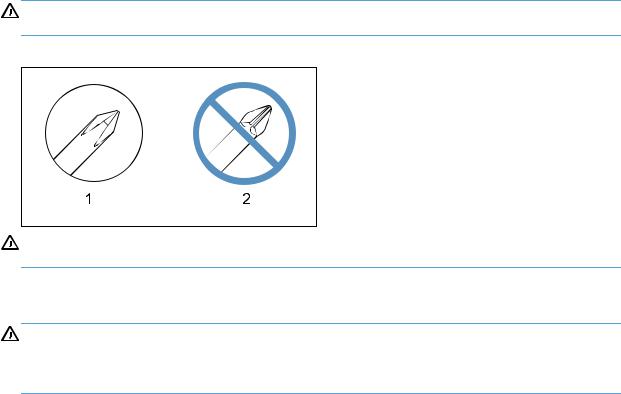
CAUTION: Always use a Phillips screwdriver (callout 1). Do not use a Pozidriv® screwdriver (callout 2) or any motorized screwdriver. These can damage screws or screw threads.
Figure 1-1 Phillips and Pozidriv screwdriver comparison
CAUTION: Avoid pulling directly on wires to disconnect wire-harness connectors. Pull on the plastic body of a connector to avoid damaging the connector wires.
Types of screws
WARNING! Make sure that components are replaced with the correct screw type. Using the incorrect screw (for example, substituting a long screw for the correct shorter screw) can cause damage to the product or interfere with product operation. Do not intermix screws that are removed from one component with the screws that are removed from another component.
For a complete list of screw types and part numbers, see the Parts chapter.
Service approach
Before performing service
●Remove all paper from the product.
●Turn off the power using the power switch.
●Unplug the power cable and interface cable or cables.
●Place the product on an ESD workstation or mat, or use an ESD strap (if one is available). If an ESD workstation, mat, or strap is not available, ground yourself by touching the sheet-metal chassis before touching an ESD-sensitive part.
ENWW |
Service approach |
3 |
●Remove the toner cartridge.
●Remove the Tray 2 cassette.
After performing service
●Plug in the power cable.
●Reinstall the toner cartridge.
●Reinstall the Tray 2 cassette.
●Load paper in the product.
Post-service test
Perform the following test to verify that the repair or replacement was successful.
Print-quality test
1.Verify that you have completed the necessary reassembly steps.
2.Make sure that the tray contains clean, unmarked paper.
3.Attach the power cord and interface cable or interface cables, and then turn on the product.
4.Verify that the expected startup sounds occur.
5.Print a configuration page, and then verify that the expected printing sounds occur.
6.Print a demo page, and then verify that the print quality is as expected.
7.Send a print job from the host computer, and then verify that the output meets expectations.
8.Clean the outside of the product with a damp cloth.
4 |
Chapter 1 Removal and replacement |
ENWW |
Parts removal order
Use the following diagram to determine which parts must be removed before removing other parts.
Figure 1-2 Parts-removal order
Component |
Remove |
Remove |
Remove |
Remove |
Remove |
Remove |
Remove |
Remove |
Toner cartridge |
|
|
|
|
|
|
|
|
|
|
|
|
|
|
|
|
|
Tray 2 cassette |
|
|
|
|
|
|
|
|
Tray 1 pickup roller |
|
|
|
|
|
|
|
|
|
|
|
|
|
|
|
|
|
Tray 1 separation pad |
Left cover |
|
|
|
|
|
|
|
Tray 1 pickup gear assembly |
Left cover |
|
|
|
|
|
|
|
|
|
|
|
|
|
|
|
|
Tray 2/3 pickup roller |
Tray 2/3 cassette |
|
|
|
|
|
|
|
Tray 2/3 separation roller |
Tray 2/3 cassette |
|
|
|
|
|
|
|
|
|
|
|
|
|
|
|
|
Document feeder pickup rollers |
|
|
|
|
|
|
|
|
Document feeder separation pad |
|
|
|
|
|
|
|
|
|
|
|
|
|
|
|
|
|
Transfer roller |
Toner cartridge |
|
|
|
|
|
|
|
Left cover |
Tray 2 cassette |
|
|
|
|
|
|
|
|
|
|
|
|
|
|
|
|
Scanner assembly |
Left cover |
|
|
|
|
|
|
|
Control panel |
Left cover |
Scanner assembly |
|
|
|
|
|
|
|
|
|
|
|
|
|
|
|
Right cover |
Left cover |
Scanner assembly |
Control panel |
|
|
|
|
|
|
|
|
|
|
|
|
|
|
Top cover |
Left cover |
Scanner assembly |
Control panel |
Right cover |
|
|
|
|
|
|
|
|
|
|
|
|
|
Rear cover and feed assembly |
Left cover |
Scanner assembly |
Control panel |
Right cover |
|
|
|
|
|
|
|
|
|
|
|
|
|
Cartridge door and |
Left cover |
Scanner assembly |
Control panel |
Right cover |
|
|
|
|
front cover assembly |
|
|
|
|
|
|
|
|
Document feeder assembly |
Left cover |
Scanner assembly |
|
|
|
|
|
|
|
|
|
|
|
|
|
|
|
Laser scanner assembly |
Left cover |
Scanner assembly |
Control panel |
Right cover |
Top cover |
|
|
|
|
|
|
|
|
|
|
|
|
Registration roller assembly |
Left cover |
Scanner assembly |
Control panel |
Right cover |
Rear cover |
Top cover |
|
|
|
|
|
|
|
and feed |
|
|
|
|
|
|
|
|
assembly |
|
|
|
Fuser assembly |
Left cover |
Scanner assembly |
Control panel |
Right cover |
Rear cover |
|
|
|
and paper feed guide |
|
|
|
|
and feed |
|
|
|
|
|
|
|
|
assembly |
|
|
|
Duplex drive assembly |
Left cover |
Scanner assembly |
Control panel |
Right cover |
Top cover |
|
|
|
|
|
|
|
|
|
|
|
|
Tray 1 solenoid |
Left cover |
|
|
|
|
|
|
|
|
|
|
|
|
|
|
|
|
Tray 2 solenoid |
Left cover |
Scanner assembly |
Control panel |
Right cover |
|
|
|
|
|
|
|
|
|
|
|
|
|
Duplex solenoid |
Left cover |
Scanner assembly |
Control panel |
Right cover |
Rear cover |
Top cover |
Fan |
Duplex drive |
|
|
|
|
|
and feed |
|
|
assembly |
|
|
|
|
|
assembly |
|
|
|
|
|
|
|
|
|
|
|
|
Main motor |
Left cover |
Scanner assembly |
Control panel |
Right cover |
Rear cover |
Top cover |
Fuser |
ECU |
|
|
|
|
|
and feed |
|
|
|
|
|
|
|
|
assembly |
|
|
|
Fan |
Left cover |
Scanner assembly |
Control panel |
Right cover |
Top cover |
|
|
|
|
|
|
|
|
|
|
|
|
Engine controller unit (ECU) PCA |
Left cover |
Scanner assembly |
Control panel |
Right cover |
Rear cover |
Top cover |
|
|
|
|
|
|
|
and feed |
|
|
|
|
|
|
|
|
assembly |
|
|
|
Formatter PCA |
Left cover |
Wireless PCA |
|
|
|
|
|
|
|
|
(wireless models) |
|
|
|
|
|
|
USB PCA |
Left cover |
|
|
|
|
|
|
|
Wireless PCA (wireless models) |
Left cover |
|
|
|
|
|
|
|
|
|
|
|
|
|
|
|
|
Fax PCA |
Left cover |
|
|
|
|
|
|
|
Power switch PCA |
Left cover |
Scanner assembly |
Control panel |
Right cover |
Front cover |
|
|
|
|
|
|
|
|
assembly |
|
|
|
Connecting PCA |
Left cover |
Scanner assembly |
Control panel |
Right cover |
|
|
|
|
|
|
|
|
|
|
|
|
|
Optional paper feeder right cover |
|
|
|
|
|
|
|
|
|
|
|
|
|
|
|
|
|
Optional paper feeder driver PCA |
Tray 3 right cover |
|
|
|
|
|
|
|
Optional paper feeder |
Tray 3 right cover |
|
|
|
|
|
|
|
paper sensor PCA |
|
|
|
|
|
|
|
|
ENWW |
Service approach |
5 |
Removal and replacement procedures
Rollers
Multipurpose (MP) tray pickup roller
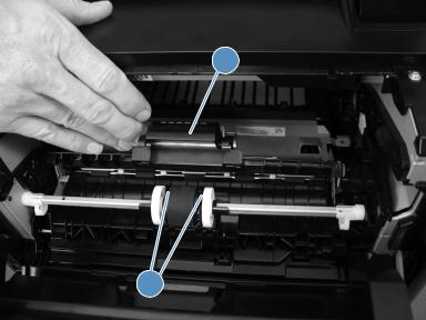
1.Open the toner cartridge door, and then remove the toner cartridge.
2.Pull back and hold the pickup roller cover (callout 1), press the tabs (callout 2) on both ends of the pickup roller away from the roller — which should cause the roller to move up — and then remove the roller.
Figure 1-3 Remove the MP tray roller
1
2
Multipurpose (MP) tray separation pad
To remove the separation pad, you must first remove the pickup roller assembly.
1.Remove the following components:
●Tray 2 cassette
●Left cover. See Left cover on page 13.
2.Open the toner cartridge door, and then remove the toner cartridge.
6 |
Chapter 1 Removal and replacement |
ENWW |
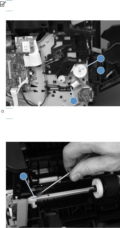
3.On the left side of the product, release the tab (callout 1) at the center of the gear, and then remove the gear (callout 2).


 NOTE: The gear is composed of two pieces. Releasing the outer tab does not remove the entire gear assembly and exposes an internal spring in the gear.
Figure 1-4 Remove the MP tray separation pad (1 of 5)
1
 2
2
3


 Reinstallation tip Press and hold back the gear arm (callout 3) when reinstalling the pickup


 gear.
gear.
4.In the toner cartridge cavity, pull back the pickup roller cover, and then use a small flat-blade screwdriver to release the tab (callout 1) on the pickup roller shaft.
Figure 1-5 Remove the MP tray separation pad (2 of 5)
1
ENWW |
Removal and replacement procedures |
7 |

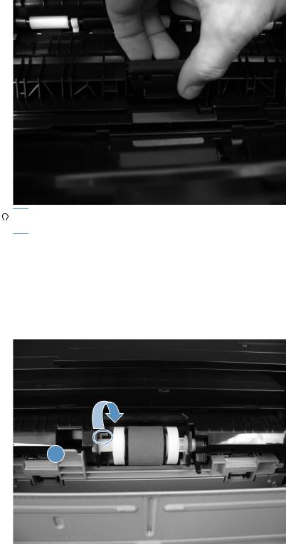
5.Move the pickup roller shaft to the left to free the right end of the shaft from the holder, and then remove the pickup roller shaft assembly to expose the separation pad.
Figure 1-6 Remove the MP tray separation pad (3 of 5)


 Reinstallation tip The spring at the right end of the shaft is not captive and might fall off


 during this process. Make sure that the spring is positioned correctly when reinstalling, as shown in the following figure.
Figure 1-7 Remove the MP tray separation pad (4 of 5)
8 |
Chapter 1 Removal and replacement |
ENWW |
6.Pull up on the top edge of the separation pad to release it from the product.
Figure 1-8 Remove the MP tray separation pad (5 of 5)


 Reinstallation tip When reinstalling the pickup roller shaft assembly, make sure that the flat


 part of the pickup roller is directly over the separation pad.
Tray 2 and optional Tray 3 pickup roller
1.Remove the tray cassette from the product.
2.Locate the pickup roller at the top of the cassette cavity. On the left roller holder, release the tab (callout 1), and then turn the holder away from you.
Figure 1-9 Remove the Tray 2 or Tray 3 pickup roller (1 of 2)
1
ENWW |
Removal and replacement procedures |
9 |
3.Push the pickup roller to the left to release the right side roller, and then pull the roller out of the product.
Figure 1-10 Remove the Tray 2 or Tray 3 pickup roller (2 of 2)
Tray 2 and optional Tray 3 separation pad
1.Remove the tray cassette from the product.
2.Locate the separation pad at the front of the cassette. On the separation pad, remove two screws (callout 1), and then remove the pad from the tray cassette.
Figure 1-11 Remove the Tray 2 or Tray 3 separation pad
1
10 Chapter 1 Removal and replacement |
ENWW |

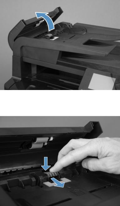
Document feeder rollers
1.Open the document feeder cover.
Figure 1-12 Remove the document feeder rollers (1 of 2)
2.On the underside of the document feeder cover, use a small flat-blade screwdriver to release the tabs (callout 1) on the left side of each roller, and then pull the rollers out of the cover.
Figure 1-13 Remove the document feeder rollers (2 of 2)
1
ENWW |
Removal and replacement procedures 11 |
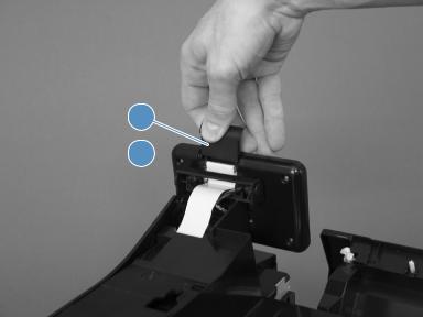
Document feeder separation pad
1.Open the document feeder cover.
Figure 1-14 Remove the document feeder separation pad (1 of 2)
2.Locate the separation pad at the end of the document feeder input tray, press down on the pad, and then slide the pad toward the input tray to remove it from the assembly.
Figure 1-15 Remove the document feeder separation pad (2 of 2)
12 Chapter 1 Removal and replacement |
ENWW |

Covers, scanner assembly, and control panel
Left cover


 NOTE: No tools are necessary to remove this cover. However, a small flat-blade screwdriver might be helpful in releasing some of the tabs that hold the cover to the product chassis.
1.Remove the Tray 2 cassette.
2.Open the toner cartridge door and the rear jam access door.
3.Grasp the front edge of the cover, and then pull the cover toward the front to release four of the seven tabs (callout 1), and then release the two tabs at the top of the cover.
Figure 1-16 Remove the left cover
1 
4.With the top and front edges loose, tip the top of the cover away from the product and then carefully slide the cover toward the back of the product to remove it.
Scanner assembly
1.Remove the following components:
●Tray 2 cassette
●Left cover. See Left cover on page 13.
2.Open the toner cartridge door and the rear jam access door.
ENWW |
Removal and replacement procedures 13 |

3.On the left side of the product, remove the ground-wire screw (callout 1), disconnect one wire connector (callout 2) on the formatter, and disconnect two flat, flexible cables (callout 3) on the formatter.
Figure 1-17 Remove the scanner assembly (1 of 2)
1
2 
3


 Reinstallation tip Do not lose the two protective guides installed on the flat, flexible cables.


 Be sure to reinstall them when you reinstall the scanner assembly.
4.At the rear of the product, remove four screws (callout 1), and then slide the scanner toward the rear of the product to remove the assembly.
Figure 1-18 Remove the scanner assembly (2 of 2)
1


 NOTE: The four scanner assembly screws removed in this step are a different size than the other screws used on the product. Set these screws aside to use when you reinstall the scanner assembly.
14 Chapter 1 Removal and replacement |
ENWW |
Control panel
1.Remove the following components:
●Tray 2 cassette
●Left cover. See Left cover on page 13.
●Scanner assembly. See Scanner assembly on page 13.
2.Open the toner cartridge door and the rear jam access door.
3.On the rear of the control panel, remove the cable cover (callout 1), disconnect one flat, flexible cable (callout 2), and then pull back the flat, flexible cable.
Figure 1-19 Remove the control panel (1 of 3)
1
2 
ENWW |
Removal and replacement procedures 15 |

4.In the cavity behind the control panel, remove two screws (callout 1)
Figure 1-20 Remove the control panel (2 of 3)
1
5.Pull the top of the control panel assembly away from the product to release the tab (callout 1) at the back of the assembly, and then pull the control panel away from the product.
Figure 1-21 Remove the control panel (3 of 3)
1
16 Chapter 1 Removal and replacement |
ENWW |

Right cover
1.Remove the following components:
●Tray 2 cassette
●Left cover. See Left cover on page 13.
●Scanner assembly. See Scanner assembly on page 13.
●Control panel. See Control panel on page 15.
2.Open the toner cartridge door and the rear jam access door.
3.Grasp the rear edge of the cover and pull that edge toward the rear to release the four tabs (callout 1) on the rear edge of the cover, and then use a small flat-blade screwdriver to release the tab (callout 2) at the top edge of the cover.
Figure 1-22 Remove the right cover
2
1 
4.With the back and top edges loose, carefully slide the cover toward the front of the product, and then remove it.
ENWW |
Removal and replacement procedures 17 |

Top cover
1.Remove the following components:
●Tray 2 cassette
●Left cover. See Left cover on page 13.
●Scanner assembly. See Scanner assembly on page 13.
●Control panel. See Control panel on page 15.
●Right cover. See Right cover on page 17.
2.Open the toner cartridge door and the rear jam access door.
3.On the left side of the product, disconnect one flat, flexible cable (callout 1) from the formatter.
Figure 1-23 Remove the top-cover assembly (1 of 3)
1
18 Chapter 1 Removal and replacement |
ENWW |

4.On the right side and the rear of the product, remove three screws (callout 1).
Figure 1-24 Remove the top-cover assembly (2 of 3)
1
5.On the top-cover assembly, remove four screws (callout 1).
Figure 1-25 Remove the top-cover assembly (3 of 3)
1
6.Lift the top-cover assembly off of the product to remove it.
ENWW |
Removal and replacement procedures 19 |
Loading...