


 Loading...
LASERJET PRO MFP
Troubleshooting Manual
M435nw
Copyright and License
© 2013 Copyright Hewlett-Packard
Development Company, L.P.
Reproduction, adaptation, or translation without prior written permission is prohibited, except as allowed under the copyright laws.
The information contained herein is subject to change without notice.
The only warranties for HP products and services are set forth in the express warranty statements accompanying such products and services. Nothing herein should be construed as constituting an additional warranty. HP shall not be liable for technical or editorial errors or omissions contained herein.
Edition 1, 5/2013
Part number: A3E42-90980
Trademark Credits
Adobe®, Acrobat®, and PostScript® are trademarks of Adobe Systems Incorporated.
Microsoft®, Windows®, Windows® XP, and Windows Vista® are U.S. registered trademarks of Microsoft Corporation.
ENERGY STAR and the ENERGY STAR mark are registered U.S. marks.

Conventions used in this guide

 TIP: Tips provide helpful hints or shortcuts.
 NOTE: Notes provide important information to explain a concept or to complete a task.
CAUTION: Cautions indicate procedures that you should follow to avoid losing data or damaging the product.
WARNING! Warnings alert you to specific procedures that you should follow to avoid personal injury, catastrophic loss of data, or extensive damage to the product.
ENWW |
iii |

Table of contents
1 Theory of operation ....................................................................................................................................... |
1 |
Basic operation ...................................................................................................................................................... |
2 |
Major systems ..................................................................................................................................... |
2 |
Product block diagram ........................................................................................................................ |
2 |
Engine control system ........................................................................................................................................... |
3 |
DC controller ........................................................................................................................................ |
4 |
Low-voltage power supply (LVPS) ...................................................................................................... |
5 |
Overcurrent/overvoltage protection ................................................................................ |
7 |
Fuser control ....................................................................................................................................... |
9 |
Fuser-heater protective function ................................................................................... |
12 |
Fuser control functions ................................................................................................... |
13 |
2 Solve problems ........................................................................................................................................... |
15 |
Solve problems checklist ..................................................................................................................................... |
16 |
Menu map ............................................................................................................................................................ |
17 |
Troubleshooting process .................................................................................................................................... |
18 |
Pre-troubleshooting checklist .......................................................................................................... |
18 |
Determine the problem source ......................................................................................................... |
19 |
Troubleshooting flowchart ............................................................................................. |
19 |
Power subsystem .............................................................................................................................. |
20 |
Power-on checks ............................................................................................................ |
20 |
Power-on troubleshooting overview ........................................................... |
20 |
Control panel checks ......................................................................................................................... |
21 |
Tools for troubleshooting ................................................................................................................................... |
23 |
Engine self-test ................................................................................................................................. |
23 |
Troubleshooting process for product not turning on ...................................................................... |
23 |
Diagrams ........................................................................................................................................... |
24 |
Block diagrams ............................................................................................................... |
24 |
Location of connectors ................................................................................................... |
25 |
DC controller connections ............................................................................ |
25 |
Paper feed driver PCA connections .............................................................. |
26 |
Duplex driver PCA connections ....................................................................................... |
27 |
ENWW |
v |
Plug and port locations ................................................................................................... |
28 |
Locations of major assemblies ....................................................................................... |
29 |
Switch locations .............................................................................................................. |
32 |
Sensor locations ............................................................................................................. |
33 |
500-sheet paper feeder accessory ................................................................................ |
34 |
Duplex unit ...................................................................................................................... |
35 |
General timing chart ....................................................................................................... |
37 |
Circuit diagrams .............................................................................................................. |
38 |
Use HP Device Toolbox (Windows) ................................................................................................... |
40 |
Internal print-quality test pages ...................................................................................................... |
41 |
Clean the paper path ....................................................................................................... |
41 |
Print the configuration page .......................................................................................... |
41 |
Print quality troubleshooting tools .................................................................................................. |
42 |
Repetitive defects ruler .................................................................................................. |
42 |
Control panel menus ......................................................................................................................... |
43 |
Setup Menu ..................................................................................................................... |
43 |
HP Web Services ........................................................................................... |
43 |
Reports menu ............................................................................................... |
44 |
Self Diagnostics menu .................................................................................. |
45 |
System Setup menu ..................................................................................... |
46 |
Service menu ................................................................................................ |
49 |
Network Setup menu .................................................................................... |
51 |
Quick Forms menu ........................................................................................ |
52 |
Function specific menus ................................................................................................. |
53 |
USB Flash Drive ............................................................................................. |
53 |
Copy Menu .................................................................................................... |
54 |
Scan Menu ..................................................................................................... |
55 |
Apps .............................................................................................................. |
55 |
Interpret control panel messages .................................................................................................... |
56 |
Control panel message types ......................................................................................... |
56 |
Control panel messages ................................................................................................. |
56 |
Rear door open ............................................................................................. |
56 |
49 Error, Turn off then on ............................................................................ |
56 |
50.x Fuser Error ............................................................................................ |
56 |
51.XX Error ................................................................................................... |
57 |
54.XX Error ................................................................................................... |
57 |
55.X Error ...................................................................................................... |
57 |
57 Fan Error, Turn off then on ..................................................................... |
57 |
59.X Error ...................................................................................................... |
58 |
79 Error Turn off then on ............................................................................. |
58 |
Black Cartridge Low ...................................................................................... |
58 |
vi |
ENWW |
Black Very Low ............................................................................................. |
58 |
Cleaning ........................................................................................................ |
59 |
Device error, press OK .................................................................................. |
59 |
Front door open ............................................................................................ |
59 |
Genuine HP supply installed ........................................................................ |
59 |
Invalid driver Press OK ................................................................................. |
59 |
Jam in Tray 1, Clear jam and then press OK ................................................. |
59 |
Load Tray 1 Press OK for available media ................................................... |
60 |
Load Tray 1 <TYPE> <SIZE>, Press OK to use available media ................... |
60 |
Load Tray 1, <PLAIN> <SIZE> / Cleaning mode, OK to start ........................ |
60 |
Manual Duplex Load Tray 1, Press OK ......................................................... |
60 |
Manual feed <SIZE> <TYPE>, Press OK to use available media .................. |
60 |
Memory is low. Press OK. ............................................................................. |
61 |
Misprint, Press OK ........................................................................................ |
61 |
Print failure, press OK. If error repeats, turn off then on. ........................... |
61 |
Tray 1 <size> To change the tray paper size, press [Modify] To accept |
|
the current value,press [OK] ........................................................................ |
61 |
Unexpected size in Tray 1 Load <size> Press OK ......................................... |
61 |
Event-log messages .......................................................................................................................... |
62 |
Print the event log .......................................................................................................... |
62 |
Show an event log ........................................................................................................... |
62 |
Event log messages ........................................................................................................ |
62 |
Clear jams ............................................................................................................................................................ |
64 |
Solve paper feed or jam problems .................................................................................................... |
64 |
The product does not pick up paper ............................................................................... |
64 |
The product picks up multiple sheets of paper .............................................................. |
64 |
Frequent or recurring paper jams .................................................................................. |
65 |
Prevent paper jams ......................................................................................................... |
65 |
Clear jams in Tray 1 ........................................................................................................................... |
66 |
Clear jams in Tray 2 ........................................................................................................................... |
68 |
Clear jams in Tray 3 (accessory) ....................................................................................................... |
72 |
Clear jams in the toner-cartridge area ............................................................................................. |
75 |
Clear jams in the rear door and fuser area ....................................................................................... |
77 |
Clear jams in the output bin .............................................................................................................. |
78 |
Clear jams in the optional duplexer .................................................................................................. |
80 |
Paper feeds incorrectly or becomes jammed ..................................................................................................... |
81 |
The product does not pick up paper ................................................................................................. |
81 |
The product picks up multiple sheets of paper ................................................................................ |
81 |
Prevent paper jams from the paper trays ........................................................................................ |
81 |
Solve image-quality problems ............................................................................................................................ |
83 |
Image defect examples ..................................................................................................................... |
83 |
ENWW |
vii |
Clean the product ................................................................................................................................................ |
90 |
Clean the pickup and separation rollers ........................................................................................... |
90 |
Clean the paper path ......................................................................................................................... |
90 |
Clean the scanner glass strip and platen .......................................................................................... |
90 |
Clean the touchscreen ....................................................................................................................... |
91 |
Solve performance problems .............................................................................................................................. |
92 |
Solve connectivity problems ............................................................................................................................... |
93 |
Solve USB connection problems ....................................................................................................... |
93 |
Solve wired network problems ......................................................................................................... |
93 |
Poor physical connection ................................................................................................ |
93 |
The computer is using the incorrect IP address for the product ................................... |
93 |
The computer is unable to communicate with the product ........................................... |
94 |
The product is using incorrect link and duplex settings for the network ...................... |
94 |
New software programs might be causing compatibility problems ............................. |
94 |
The computer or workstation might be set up incorrectly ............................................ |
94 |
The product is disabled, or other network settings are incorrect ................................. |
94 |
Solve wireless network problems .................................................................................................... |
94 |
Wireless connectivity checklist ...................................................................................... |
95 |
The product does not print after the wireless configuration completes ...................... |
95 |
The product does not print, and the computer has a third-party firewall installed ..... |
96 |
The wireless connection does not work after moving the wireless router or |
|
product ............................................................................................................................ |
96 |
Cannot connect more computers to the wireless product ............................................ |
96 |
The wireless product loses communication when connected to a VPN ........................ |
96 |
The network does not appear in the wireless networks list .......................................... |
96 |
The wireless network is not functioning ........................................................................ |
96 |
Perform a wireless network diagnostic test .................................................................. |
97 |
Reduce interference on a wireless network ................................................................... |
97 |
Service mode functions ....................................................................................................................................... |
98 |
Service menu ..................................................................................................................................... |
98 |
Service menu settings .................................................................................................... |
98 |
Restore the factory-set defaults .................................................................................... |
98 |
Secondary service menu ................................................................................................................... |
98 |
Open the secondary service menu ................................................................................. |
99 |
Secondary service menu structure ................................................................................. |
99 |
Product resets ................................................................................................................................. |
100 |
NVRAM initialization ..................................................................................................... |
100 |
Super NVRAM initialization ........................................................................................... |
101 |
Product updates ................................................................................................................................................ |
102 |
Manually update the firmware ....................................................................................................... |
102 |
Set the product to automatically update the firmware ................................................................. |
102 |
viii |
ENWW |
Appendix A Service and support .................................................................................................................... |
103 |
Hewlett-Packard limited warranty statement ................................................................................................. |
104 |
HP's Premium Protection Warranty: LaserJet toner cartridge limited warranty statement ........................... |
105 |
HP policy on non-HP supplies ........................................................................................................................... |
106 |
HP anticounterfeit Web site .............................................................................................................................. |
107 |
Data stored on the toner cartridge ................................................................................................................... |
108 |
End User License Agreement ............................................................................................................................ |
109 |
OpenSSL ............................................................................................................................................................. |
111 |
Customer self-repair warranty service ............................................................................................................. |
112 |
Customer support .............................................................................................................................................. |
113 |
Appendix B Product specifications ................................................................................................................. |
115 |
Physical specifications ...................................................................................................................................... |
116 |
Power consumption, electrical specifications, and acoustic emissions .......................................................... |
116 |
Environmental specifications ............................................................................................................................ |
116 |
Appendix C Regulatory information ............................................................................................................... |
117 |
FCC regulations .................................................................................................................................................. |
118 |
Environmental product stewardship program ................................................................................................. |
119 |
Protecting the environment ........................................................................................................... |
119 |
Ozone production ............................................................................................................................ |
119 |
Power consumption ........................................................................................................................ |
119 |
Toner consumption ......................................................................................................................... |
119 |
Paper use ......................................................................................................................................... |
119 |
Plastics ............................................................................................................................................ |
119 |
HP LaserJet print supplies .............................................................................................................. |
119 |
Return and recycling instructions ................................................................................................... |
120 |
United States and Puerto Rico ...................................................................................... |
120 |
Multiple returns (more than one cartridge) ............................................... |
120 |
Single returns ............................................................................................. |
120 |
Shipping ...................................................................................................... |
120 |
Non-U.S. returns ........................................................................................................... |
121 |
Paper ............................................................................................................................................... |
121 |
Material restrictions ........................................................................................................................ |
121 |
Disposal of waste equipment by users ........................................................................................... |
122 |
Electronic hardware recycling ........................................................................................................ |
122 |
Chemical substances ....................................................................................................................... |
122 |
Material Safety Data Sheet (MSDS) ................................................................................................ |
122 |
For more information ...................................................................................................................... |
122 |
Declaration of conformity ................................................................................................................................. |
123 |
ENWW |
ix |
Certificate of Volatility ...................................................................................................................................... |
125 |
Safety statements ............................................................................................................................................. |
127 |
Laser safety ..................................................................................................................................... |
127 |
Canadian DOC regulations .............................................................................................................. |
127 |
VCCI statement (Japan) ................................................................................................................... |
127 |
Power cord instructions .................................................................................................................. |
127 |
EMC statement (China) .................................................................................................................... |
127 |
Power cord statement (Japan) ....................................................................................................... |
128 |
EMC statement (Korea) ................................................................................................................... |
128 |
EMI statement (Taiwan) .................................................................................................................. |
128 |
Laser statement for Finland ........................................................................................................... |
128 |
GS statement (Germany) ................................................................................................................ |
130 |
Substances Table (China) ................................................................................................................ |
130 |
Restriction on Hazardous Substances statement (Turkey) ........................................................... |
130 |
Restriction on Hazardous Substances statement (Ukraine) .......................................................... |
130 |
Eurasian Conformity (Belarus, Kazakhstan, Russia) ...................................................................... |
131 |
Additional statements for wireless products ................................................................................................... |
132 |
FCC compliance statement—United States ................................................................................... |
132 |
Australia statement ........................................................................................................................ |
132 |
Brazil ANATEL statement ................................................................................................................ |
132 |
Canadian statements ...................................................................................................................... |
132 |
Products with 5 GHz Operation Industry of Canada ....................................................................... |
132 |
Exposure to Radio Frequency Radiation (Canada) ......................................................................... |
132 |
European Union regulatory notice .................................................................................................. |
133 |
Notice for use in France .................................................................................................................. |
133 |
Notice for use in Russia ................................................................................................................... |
133 |
Mexico statement ........................................................................................................................... |
133 |
Taiwan statement ........................................................................................................................... |
134 |
Korean statement ........................................................................................................................... |
134 |
Vietnam Telecom wired/wireless marking for ICTQC Type approved products ............................ |
134 |
Index ........................................................................................................................................................... |
135 |
x |
ENWW |

1 Theory of operation
This chapter presents an overview of the major components of the HP LaserJet Pro M435 Series, and includes a detailed discussion of the image-formation system.
ENWW |
1 |
Basic operation
Major systems
The product contains the following systems:
●Engine-control system
●Laser/scanner system
●Image-formation system
●Paper feed system
●Accessories
Product block diagram
Figure 1-1 Product block diagram
Laser scanner system
Image-formation system
Engine-control system
Pickup, feed and delivery system
Accessory
2 Chapter 1 Theory of operation |
ENWW |

Engine control system
The engine control system coordinates all product functions and drives the other four systems. The engine control system contains these components:
●DC controller PCA
●High-voltage power supply PCA
●Low-voltage power supply unit
●Fuser control
Figure 1-2 Engine control system
Engine-control system
Laser scanner system
DC controller
Image-formation system
Low-voltage power supply
Formatter
High-voltage power supply
Pickup, feed and delivery system
Fuser control
Accessory
Table 1-1 Sequence of operation
Period |
Duration |
Purpose |
Remarks |
WAIT period |
From the time the power is |
|
turned on until the initial drive |
|
for the main motor is complete |
Removes the charge that |
Detects cartridge presence |
creates a potential difference |
|
from the drum surface, and |
|
adjusts the drum phase |
|
STBY (Standby period) |
From end of the WAIT or LSTR |
Maintains the product in |
|
period until either the print |
readiness for a print command |
|
command is received from the |
and maintains the heater at a |
|
formatter or the power is |
targeted temperature |
|
turned off |
|
|
|
|
INTR (Initial rotation) |
From the time the print |
Prepares the photosensitive |
|
command is received until the |
drum for printing and cleans |
|
pickup solenoid is turned on |
the transfer charging roller |
|
|
|
ENWW |
Engine control system 3 |
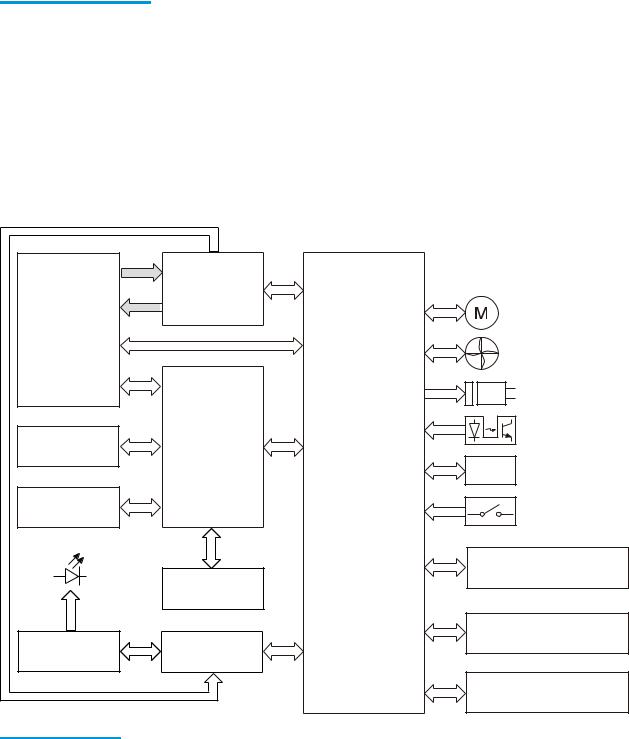
Table 1-1 Sequence of operation (continued)
Period |
Duration |
Purpose |
Remarks |
|
|
|
|
From the end of INTR period |
Forms the images on the |
|
|
|
until the fuser paper sensor |
photosensitive drum and |
|
|
detects the trailing edge of |
transfers the toner image to |
|
|
paper |
the print media |
|
|
|
|
|
LSTR (Last rotation) |
From the end of the PRINT |
Moves the last printed sheet |
The product enters the INTR |
|
period until the fuser motor |
out of the product |
period as soon as the formatter |
|
stops rotating |
|
sends another print command |
|
|
|
|
DC controller
Figure 1-3 DC controller |
|
|
AC |
|
|
input |
|
|
|
Low-voltage |
|
|
power supply |
|
|
Motor |
|
Fuser |
|
|
|
Fan |
|
|
Solenoid |
|
|
Photointerrupter |
|
Transfer roller |
High-voltage |
|
power supply |
||
|
||
|
Sensor |
|
Cartridge |
DC controller |
|
Switch |
||
LED |
Duplex unit |
|
Static charge |
||
|
||
|
eliminator |
|
|
Input accessory |
|
Control panel |
Formatter |
|
|
Laser scanner ass’y |
Table 1-2 DC controller components
Component type |
Abbreviation |
Component name |
|
|
|
Motor |
M1 |
Drum motor |
|
|
|
|
M2 |
Fuser motor |
|
|
|
|
M3 |
Scanner motor |
|
|
|
4 Chapter 1 Theory of operation |
ENWW |

Table 1-2 DC controller components (continued)
Component type |
Abbreviation |
Component name |
|
|
|
Fan |
FM1 |
Main fan |
|
|
|
|
FM2 |
Sub fan |
|
|
|
Solenoid |
SL1 |
Cassette pickup solenoid |
|
|
|
|
SL2 |
MP tray pickup solenoid |
|
|
|
Switch |
SW1 |
Front interlock switch |
|
|
|
|
SW2 |
Rear interlock switch |
|
|
|
|
SW3 |
Cassette-presence switch |
|
|
|
|
SW4 |
Cartridge door open detection switch |
|
|
|
Photointerruptor |
PS1 |
TOP sensor |
|
|
|
|
PS2 |
Loop sensor |
|
|
|
|
PS3 |
Fuser delivery sensor |
|
|
|
|
PS4 |
Delivery tray paper-full sensor |
|
|
|
|
PS5 |
Cassette paper-presence sensor |
|
|
|
|
PS6 |
MP tray paper-presence sensor |
|
|
|
Sensor |
|
Environment sensor |
|
|
|
Low-voltage power supply (LVPS)
The low-voltage power supply (LVPS) converts AC input voltage to DCvoltage. The LVPS has two fuses on the PCA. The LVPS 24 V output is interrupted to the fuser and the high-voltage power supply if the cartridge-door interlock switch (SW501) is in the off position (cover open).
WARNING! The product power switch only interrupts DC voltage from the LVPS. The AC voltage is present in the product when the power cable is plugged into a power receptacle and the power switch is in the off position. You must disconnect the product power cable before servicing the product.
ENWW |
Engine control system 5 |
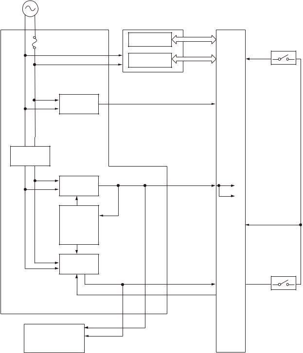
Figure 1-4 Low voltage power supply
AC input
Low-voltage power supply |
High-voltage power supply |
DC controller |
|
Fuse |
High-voltage |
Interlock switch |
|
circuit |
|||
FU1 |
SW2 |
||
|
|||
|
Fuser circuit |
+24VC |
|
|
|
||
Zerocross |
/ZEROX |
|
|
circuit |
|
|
|
Rectifying |
|
|
|
circuit |
|
|
|
+3.3V |
+3.3VA |
+3.3VA |
|
generation |
|
+3.3VC |
|
circuit |
|
||
Protection |
|
+24VB |
|
|
|
||
circuit |
|
|
|
+24V |
|
|
|
generation |
|
+24VB |
|
circuit |
|
|
|
|
+24VA |
+24VA |
|
|
RMT_24V |
Interlock switch |
|
|
|
||
|
|
SW1 |
|
+3.3VA |
|
|
|
+24VA |
|
|
|
Formatter |
|
|
6 Chapter 1 Theory of operation |
ENWW |

Table 1-3 Low-voltage power supply
Main DC voltage |
Sub- |
Behavior |
|
|
voltage |
|
|
|
|
|
|
+24V |
+24VA |
● |
Constantly supplied |
|
|
● Stopped during Sleep mode |
|
|
|
|
|
|
+24VB |
● Interrupted when the rear door open |
|
|
|
● Stopped during Sleep mode |
|
|
|
|
|
|
+24VC |
● Interrupted when the cartridge door open |
|
|
|
● Stopped during Sleep mode |
|
|
|
|
|
+3.3V |
+3.3VA |
● |
Constantly supplied |
|
|
|
|
|
+3.3VB |
● |
Constantly supplied |
|
|
|
|
|
+3.3VC |
● |
Constantly supplied |
|
● Stopped during Sleep mode |
|
|
|
|
|
Table 1-4 Low-voltage power supply functions. |
|
|
|
|
|
Function |
Applied |
|
|
|
|
Sleep mode |
V |
|
|
|
|
Power supply voltage detection |
N/A |
|
|
|
|
Automatic power OFF |
V |
|
|
|
|
Automatic power ON/OFF |
N/A |
|
|
|
|
Active OFF |
V |
|
|
|
|
Inactive OFF |
V |
|
|
|
|
Network mode |
N/A |
|
|
|
|
Power switch illumination |
V |
|
|
|
|
Low-voltage power supply failure detection |
V |
|
|
|
|
Power save mode |
N/A |
|
|
|
Overcurrent/overvoltage protection |
|
|
The low-voltage power supply has a protective function against overcurrent and overvoltage to prevent failures in the power supply circuit. If the DC power is not being supplied from the low-voltage power supply, the protective function might be running. In such case, turn off the power switch and disconnect the power cable. Do not connect the power cable or turn on the power switch again until the cause is found.
If the DC power is not being supplied from the low-voltage power supply, the protective function might be running. In such case, turn off the power switch and disconnect the power cable. Do not connect the power cable or turn on the power switch again until the cause is found.
ENWW |
Engine control system 7 |

WARNING! If you believe the overcurrent or overvoltage protection circuits have been activated, do not connect the product power cable or turn on the product power until the cause of the failure is found and corrected.
In addition, two fuses in the low-voltage power supply protect against overcurrent. If overcurrent flows into the AC line, the fuses melt and cut off the power distribution.
For safety reasons, the product interrupts power (24 V) to the main motor and high-voltage power supply. The interloct switch is turned off to interrupt power when the cartidge door opens (SW260 is turned off). The AC voltage remains present in the product when the power switch is in the off position. Disconnect the power cable when disassembling the product.


 NOTE: An accidental electrical short while servicing the product can result in a loss of power to the product causing the control panel to shut down (blank out). Turn the product power off, and then unplug the power cable. Wait at least 15 minutes before plugging the power cable in and turning the product power on.
8 Chapter 1 Theory of operation |
ENWW |
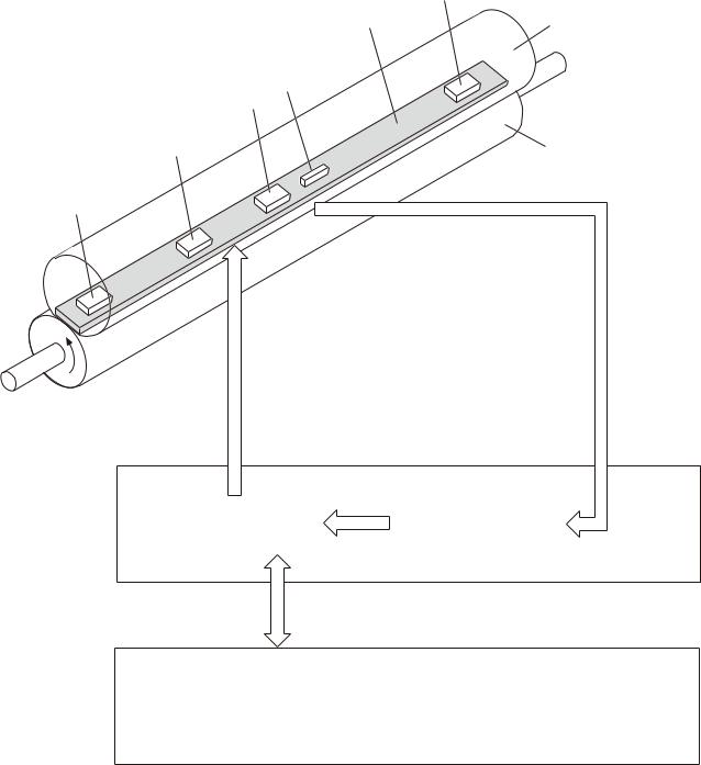
Fuser control
The fuser-heater control circuit and the fuser-heater safety circuit control the fuser temperature according to commands from the DC controller. The product uses an on-demand fusing method.
Figure 1-5 Fuser components
TH4
H1/H2 |
Fuser film |
FU1
TH1
TH2
Pressure roller
TH3
FUSER TEMPERATURE signal
FUSER HEATER CONTROL signal
Fuser heater control circuit |
|
Fuser heater safety circuit |
|
|
|
High-voltage power supply
DC controller
ENWW |
Engine control system 9 |

Table 1-5 Fuser control components
Component name |
|
Function |
|
|
|
H1 |
Fuser main heater |
Heats the center area of the fuser film |
|
|
|
H2 |
Fuser sub heater |
Heats the edge of the fuser film |
|
|
|
TH1 |
Main thermistor |
Detects the center temperature of the fuser heater (contact type) |
|
|
|
TH2 |
Sub thermistor 1 |
Detects the temperature at one end of the fuser heater (contact type) |
|
|
|
TH3 |
Sub thermistor 2 |
|
|
|
|
TH4 |
Sub thermistor 3 |
|
|
|
|
FU1 |
Thermal fuse |
Prevents an abnormal temperature rise of the fuser heater (non-contact |
|
|
type) |
|
|
|
10 Chapter 1 Theory of operation |
ENWW |

Figure 1-6 Fuser control system |
|
|
||
|
|
AC input |
|
|
|
|
|
Low-voltage power supply |
DC controller |
|
|
|
Zerocross |
ZEROX |
|
|
|
circuit |
|
|
|
|
|
|
|
|
|
High-voltage power supply |
|
|
|
RL101 |
|
RLD |
|
|
|
Relay drive circuit |
|
|
|
RL102 |
|
|
|
|
|
|
|
|
|
Fuser heater |
|
FSRD1 |
|
|
|
FSRD2 |
|
|
|
control circuit |
|
|
|
|
|
|
|
|
Fuser heater safety circuit |
Current |
|
|
|
detection |
FSRCUR |
||
|
|
|
circuit |
|
|
|
|
Fuser control circuit |
|
|
|
|
|
MFSRTH |
|
|
|
|
S1FSRTH |
|
|
|
|
S2FSRTH |
|
|
|
|
S3FSRTH |
|
Fuser |
|
|
|
Fuser film ass’y |
|
|
||
|
TH2 |
TH1 |
|
|
FU1 |
TH3 |
TH4 |
|
|
|
|
|
|
|
|
H1/H2 |
|
|
|
Pressure roller
ENWW |
Engine control system 11 |
Fuser-heater protective function
The fuser-heater protective function detects an abnormal temperature rise of the fuser and interrupts the power supply to the fuser heater. The following protective components prevent an abnormal temperature rise of the fuser-heater:
●DC controller
The DC controller monitors the detected temperature of the thermistor. The DC controller deactivates the FUSER HEATER CONTROL signal and releases the relay (RL1001) to interrupt the power supply to the fuser heater when it detects an abnormal temperature.
●Fuser-heater safety circuit
The fuser-heater safety circuit monitors the detected temperature of the thermistor. The fuser-heater safety circuit releases the relays (RL1001 and RL1002) or deactivates the fuser-heater control circuit to interrupt the power supply to the fuser-heater, when it detects an abnormal temperature.
●Thermoswitch
The contact of the thermoswitch is broken to interrupt the power supply to the fuser heater when the temperature of the fuser heater is abnormally high.
●Current detection circuit
The current detection circuit monitors the current flowing through the fuser heater control circuit. The current detection circuit releases the relays (RL101, RL102) to interrupt power supply to the fuser heater when it detects an abnormal current value.
The DC controller deactivates the FUSER HEATER CONTROL signal to interrupt power supply to the fuser heater when the current of the CURRENT DETECTION signal is higher than a specified value.
12 Chapter 1 Theory of operation |
ENWW |

Fuser control functions
The product has the following fuser control functions.
Table 1-6 Fuser control functions
Function |
Applied |
|
|
Fuser temperature control |
V |
|
|
Fuser failure detection |
V |
|
|
Frequency detection circuit failure detection |
V |
|
|
Fuser depressurization mechanism failure detection |
N/A |
|
|
Fuser type discrepancy detection |
N/A |
|
|
Fuser type identification detection |
N/A |
|
|
Fuser presence detection |
V |
|
|
Fuser life detection |
N/A |
|
|
Relay failure detection |
N/A |
|
|
Pressure roller cleaning |
V |
|
|
ENWW |
Engine control system 13 |

2 Solve problems


 NOTE: To perform diagnostic and configuration procedures (for example, resetting page counts) for the product, you must install the CP1210 Service Config Tool (available at your HP authorized repair center).
●Solve problems checklist
●Menu map
●Troubleshooting process
●Tools for troubleshooting
●Clear jams
●Paper feeds incorrectly or becomes jammed
●Solve image-quality problems
●Clean the product
●Solve performance problems
●Solve connectivity problems
●Service mode functions
●Product updates
ENWW |
15 |
Solve problems checklist
1.Ensure that the product is set up correctly.
a.Press the power button to turn on the product or to deactivate the Auto-Off mode.
b.Check the power-cable connections.
c.Ensure that the line voltage is correct for the product power configuration. (See the label in the cartridge door for voltage requirements.) If you are using a power strip and its voltage is not within specifications, plug the product directly into the wall. If it is already plugged into the wall, try a different outlet.
2.Check the cable connections.
a.Check the cable connection between the product and the computer. Ensure that the connection is secure.
b.Ensure that the cable itself is not faulty by using a different cable, if possible.
c.Check the network connection. Ensure the network light is lit. The network light is next to the network port on the back of the product.
If the product remains unable to connect to the network, uninstall and then reinstall the product. If the error persists, contact a network administrator.
3.Check to see if any messages appear on the control panel.
4.Ensure that the paper you are using meets specifications.
5.Ensure that the paper is loaded correctly in the input tray.
6.Ensure that the product software is installed correctly.
7.Verify that you have installed the printer driver for this product, and that you are selecting this product from the list of available printers.
8.Print a configuration page.
a.If the page does not print, verify that the input tray contains paper and that the paper is properly loaded.
b.Ensure that the toner cartridge is installed correctly.
c.If the paper jams in the product, clear the jam.
d.If the print quality is unacceptable, complete the following steps:
●Verify that the print settings are correct for the paper you are using.
●Solve the print-quality problems.
9.Print a small document from a different program that has printed in the past. If this solution works, then the problem is with the program you are using. If this solution does not work (the document does not print), complete these steps:
a.Try printing the job from another computer that has the product software installed.
b.Check the cable connection. Direct the product to the correct port, or reinstall the software, selecting the connection type you are using.
16 Chapter 2 Solve problems |
ENWW |
Menu map
Use the following procedure to print a control panel menu layout map.
1.From the Home screen, touch the Setup button.
2.Touch the Reports button.
3.Touch the Menu Structure button.
ENWW |
Menu map 17 |

Troubleshooting process
When the product malfunctions or encounters an unexpected situation, the product control panel alerts you to the situation. This chapter contains information to help diagnose and solve problems.
●Use the pre-troubleshooting checklist to evaluate the source of the problem and to reduce the number of steps that are required to fix the problem.
●Use the troubleshooting flowchart to pinpoint the root cause of hardware malfunctions. The flowchart guides you to the section of this chapter that contains steps for correcting the malfunction.
Before beginning any troubleshooting procedure, check the following issues:
●Are supply items within their rated life?
●Does the configuration page reveal any configuration errors?
 NOTE: The customer is responsible for checking supplies and for using supplies that are in good condition.
Pre-troubleshooting checklist
The following table includes basic questions to ask the customer to quickly help define the problem(s).
General topic |
Questions |
|
|
|
|
Environment |
● |
Is the product installed on a solid, level surface (± 1°)? |
|
● |
Is the power-supply voltage within ± 10 volts of the specified power source? |
|
● |
Is the power-supply plug inserted in the product and the outlet? |
|
● |
Is the operating environment within the specified parameters? |
|
● |
Is the product exposed to ammonia gas, such as that produced by diazo copiers or |
|
|
office cleaning materials? |
|
|
NOTE: Diazo copiers produce ammonia gas as part of the copying processes. |
|
|
Ammonia gas (from cleaning supplies or a diazo copier) can have an adverse effect |
|
|
on some product components (for example, the toner cartridge OPC). |
|
● |
Is the product exposed to direct sunlight? |
|
|
|
Paper |
● |
Does the customer use only supported paper? |
|
● |
Is the paper in good condition (no curls, folds, or distortion)? |
|
● |
Is the paper stored correctly and within environmental limits? |
|
|
|
Input trays |
● |
Is the amount of paper in the tray within specifications? |
|
● |
Is the paper correctly placed in the tray? |
|
● |
Are the paper guides aligned with the stack? |
|
● |
Is the tray correctly installed in the product? |
|
|
|
Toner cartridge |
● |
Is the toner cartridge installed correctly? |
|
|
|
Transfer unit and fuser |
● |
Are the transfer unit and fuser installed correctly? |
|
|
|
Covers |
● |
Is the front cover closed? |
|
|
|
18 Chapter 2 Solve problems |
ENWW |

General topic |
Questions |
|
|
|
|
Condensation |
● |
Does condensation occur following a temperature change (particularly in winter |
|
|
following cold storage)? If so, wipe affected parts dry or leave the product on for |
|
|
10 to 20 minutes. |
|
● |
Was a toner cartridge opened soon after being moved from a cold to a warm room? |
|
|
If so, allow the toner cartridge to sit at room temperature for 1 to 2 hours. |
|
|
|
Miscellaneous |
● |
Check for and remove any non-HP components (toner cartridges, for example) |
|
|
from the product. |
|
● |
Remove the product from the network to ensure that the failure is associated with |
|
|
the product before beginning troubleshooting. |
|
● |
For any print-quality issues, calibrate the product. |
|
|
|
Determine the problem source
When the product malfunctions or encounters an unexpected situation, the product control panel alerts you to the situation. The troubleshooting flowchart helps you diagnose the root cause of the problem. The remainder of this chapter provides steps for correcting problems.
Troubleshooting flowchart
This flowchart highlights the general processes that you can follow to quickly isolate and solve product hardware problems.
Each row depicts a major troubleshooting step. A “yes” answer to a question allows you to proceed to the next major step. A “no” answer indicates that more testing is needed. Go to the appropriate section in this chapter, and follow the instructions there. After completing the instructions, go to the next major step in this troubleshooting flowchart.
Table 2-1 Troubleshooting flowchart
1 |
Is the product on and does a readable message |
Follow the power-on troubleshooting checks. See Power subsystem |
|||||||
Power on |
display? |
|
|
|
|
|
on page 20. |
||
|
|
|
|
|
|
|
|
|
|
Yes |
|
|
No |
|
|
|
After the control panel display is functional, see step 2. |
||
|
|
|
|
|
|
||||
|
|
|
|
|
|||||
|
|
|
|
||||||
2 |
Does the message Ready display on the control |
1. Follow the control panel message to resolve the problem. Touch |
|||||||
Control panel |
panel? |
|
|
|
|
|
the button to get more information. |
||
|
|
|
|
|
|
|
|
|
|
|
|
|
No |
|
|
|
|
|
|
messages |
Yes |
|
|
|
|
2. If more information is required to troubleshoot the problem, |
|||
|
|||||||||
|
|
|
|||||||
|
|
|
|
|
|
|
|
|
refer to the troubleshooting section of the product user guide. |
|
|
|
|
|
|
|
|
|
After the errors have been corrected, go to step 3. |
|
|
|
|
||||||
3 |
Open the Troubleshooting menu and print an |
If the event log does not print, check for error messages. |
|||||||
Event log |
event log to see the history of errors with this |
If paper jams inside the product, see the jams section of the product |
|||||||
product. |
|
|
|
|
|
||||
|
Does the event log print? |
|
|
|
|
|
service manual. |
||
|
|
|
|
|
|
If error messages display on the control panel when you try to print an |
|||
|
|
|
|
|
|
|
|
|
|
|
|
|
|
No |
|
|
|
|
|
|
Yes |
|
|
|
|
event log, see the control panel message section of the service |
|||
|
|
||||||||
|
|
|
|
||||||
|
|
|
|
|
|
|
|
|
manual. |
|
|
|
|
|
|
|
|
|
After successfully printing and evaluating the event log, see step 4. |
|
|
|
|
|
|
|
|
|
|
ENWW |
Troubleshooting process 19 |

Table 2-1 Troubleshooting flowchart (continued)
|
4 |
|
Open the Reports menu and print the |
|
If accessories that are installed are not listed on the configuration |
|
|||||||
|
|
|
|
||||||||||
|
Information pages |
|
configuration pages to verify that all the |
|
page, remove the accessory and reinstall it. |
|
|||||||
|
|
accessories are installed. |
|
|
|
|
|
|
After evaluating the configuration pages, see step 5. |
|
|||
|
|
|
Are all the accessories installed? |
|
|
||||||||
|
|
|
|
|
|
||||||||
|
|
|
|
|
|
|
|
|
|
|
|
|
|
|
|
|
Yes |
|
|
No |
|
|
|
|
|
|
|
|
|
|
|
|
|
|
|||||||
|
|
|
|
|
|
|
|
|
|
||||
|
|
|
|
|
|
|
|
||||||
|
5 |
|
Does the print quality meet the customer's |
|
Compare the images with the sample defects in the image defect |
|
|||||||
|
Image quality |
|
requirements? |
|
|
|
|
|
|
tables. See the images defects table in the product service manual. |
|
||
|
|
|
|
|
|
|
|
|
|
|
|
|
|
|
|
Yes |
|
|
No |
|
|
|
|
|
After the print quality is acceptable, see step 6. |
|
|
|
|
|
|
|
|
|
|
|
|||||
|
|
|
|
|
|
||||||||
|
|
|
|
|
|
|
|
||||||
|
6 |
|
Can the customer print successfully from the |
|
Verify that all I/O cables are connected correctly and that a valid |
|
|||||||
|
Interface |
|
host computer? |
|
|
|
|
|
|
IP address is listed on the Jetdirect configuration page. |
|
||
|
|
|
|
|
|
|
|
|
|
|
|
|
|
|
|
Yes. This is the end of |
No |
|
|
|
|
If error messages display on the control panel when you try to print an |
|
||||
|
|
|
|
|
|
|
|||||||
|
|
|
|
||||||||||
|
|
|
the troubleshooting |
|
|
|
|
|
|
event log, see the control panel message section of the service |
|
||
|
|
|
process. |
|
|
|
|
|
|
manual. |
|
||
|
|
|
|
|
|
|
|
|
|
|
|
When the customer can print from the host computer, this is the end of |
|
|
|
|
|
|
|
|
|
|
|
|
|
the troubleshooting process. |
|
|
|
|
|
|
|
|
|
|
|
|
|
|
|
Power subsystem
Power-on checks
The basic product functions should start up when the product is connected into an electrical outlet and the power switch is pushed to the on position. If the product does not start, use the information in this section to isolate and solve the problem.
Power-on troubleshooting overview
Turn on the product power. If the control panel display remains blank, random patterns display, or asterisks remain on the control panel display, perform power-on checks to find the cause of the problem.
During normal operation, the main cooling fan begins to spin briefly after the product power is turned on. Place your hand over the holes in the right-side cover, near the formatter. If the fan is operating, you will feel air passing out of the product. You can also lean close to the product and hear the fan operating. Place your hand over the hole in the right-rear upper corner. When this fan is operational, the DC side of the power supply is functioning correctly.
After the fan is operating, the main motor turns on (unless the rear or front cover is open, a jam condition is sensed, or the paper-path sensors are damaged). You might be able to visually and audibly determine if the main motor is turned on.
If the fan and main motor are operating correctly, the next troubleshooting step is to isolate print engine, formatter, and control panel problems. Perform an engine test and if the formatter is damaged, it might interfere with the engine test. If the engine test is then successful, the problem is almost certainly with the formatter, the control panel, or the cable that connects them.
See Engine self-test on page 23 for instructions on performing an engine self test.
If the control panel is blank when you turn on the product, check the following items.
20 Chapter 2 Solve problems |
ENWW |
1.Make sure that the product is connected directly into an active electrical outlet (not a power strip) that delivers the correct voltage.
2.Make sure that the power switch is in the on position.
3.Make sure that the fan runs briefly, which indicates that the power supply is operational.
4.Make sure that the control panel display wire harness is connected.
5.Make sure that the formatter is seated and operating correctly. Turn off the product and remove the formatter. Reinstall the formatter, and then verify that the formatter LED is blinking.
6.Remove any external solutions, and then try to turn the product on again.


 NOTE: If the control panel display is blank, but the main cooling fan runs briefly after the product power is turned on, try printing an engine-test page to determine whether the problem is with the control panel display, formatter, or other product assemblies. See Troubleshooting process for product not turning on on page 23.
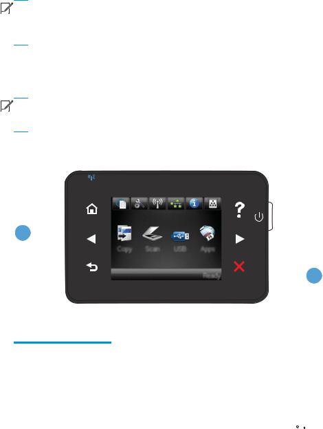
Control panel checks
Use the product control panel to conduct tests on the control panel LEDs, display, or buttons.


 NOTE: When the menus are accessed, some of the touchscreen buttons located along the sides of the control panel display are not illuminated. Use the figure below to locate the Cancel
  button and the left arrow button to access the control panel tests.
Figure 2-1 Control panel 2ndary Service test access buttons
1
 2
2
Table 2-2 Control panel 2ndary Service test access buttons
Item |
Description |
|
|
1 |
Left arrow button |
|
|
2 |
Cancel button |
|
|
1.From the Home screen on the product control panel, touch the Setup  button.
2.Touch the left arrow button, and then quickly touch the Cancel button. The display should return to Ready status.
ENWW |
Troubleshooting process 21 |
3.Touch the Setup button again to open the menus. The first menu should be the 2ndary Service menu.
4.Touch the 2ndary Service menu, and then scroll to one of the following menu items.
●LED Test
●Display Test
●Button Test
5.Touch the menu item to begin the test.
6.After completing the test, return the product to the Ready state, and then touch the Cancel  button to remove the 2ndary Service menu from the menu list.
22 Chapter 2 Solve problems |
ENWW |
Loading...