


 Loading...
Latex 300 Printer Series
Service Manual
Publication Date: April 2014
Edition: Edition 1
© 2014 Hewlett-Packard Development |
Legal notices |
Company, L.P. |
This document contains proprietary |
|
|
|
information that is protected by copyright. All |
|
rights are reserved. No part of this document |
|
may be photocopied, reproduced, or translated |
|
to another language without the prior written |
|
consent of Hewlett-Packard Company. |
Warranty
The information contained in this document is subject to change without notice.
Hewlett-Packard makes no warranty of any kind with regard to this material, including, but not limited to, the implied warranties of merchantability and fitness for a particular purpose.
Hewlett-Packard shall not be liable for errors contained herein or for incidental or consequential damages in connection with the furnishing, performance, or use of this material.
Safety
The procedures described in this manual are to be performed by HP-qualified service personnel only.
Electrical shock hazard
•Ensure that the AC power outlet (mains) has a protective earth (ground) terminal.
•Disconnect the printer (both power cords) from the power source performing any maintenance or servicing operation. The rear switch is not the disconnecting device, unplug all power cords before servicing the printer.
•Prevent water or any other liquids from running onto electrical components or circuits, or through openings in the enclosure.
Electrostatic discharge
See the beginning of Chapter 4 of this manual for precautions you should take to prevent damage to the printer circuits from electrostatic discharge.
Safety symbols
Serious hazards leading to death, injury, or damage may result if you do not take the following precautions:
•The Warning symbol calls attention to a procedure, practice, or the like, which, if not correctly performed or adhered to, could result in personal injury. Do not proceed beyond a Warning symbol until the indicated conditions are fully understood and met.
•The Caution symbol calls attention to an operating procedure, practice, or the like, which, if not correctly performed or adhered to, could result in damage to or destruction of part or all of the printer. Do not proceed beyond a Caution symbol until the indicated conditions are fully understood and met.
Using this manual
Purpose
This service manual contains information necessary to test, calibrate, and service the HP Latex 300 printer series.
For information about using the printer, see the user’s guide.
Chapters
1 Printer systems
Use this chapter as a reference for technical information about the subsystems, components, and how they work together.
Of particular importance are the diagrams included for each subsystem of the printer. They can be useful for both troubleshooting and disassembly.
2 Troubleshooting
Whenever a printer is not functioning correctly due to a fault, use this chapter for step-by-step diagnosis until you arrive at the solution, which may include replacing a part.
Troubleshooting always begins with a problem; so, when you enter the chapter, navigate to the proper section and find the troubleshooting steps for your problem.
This chapter does not cover the procedures for the diagnostic tests you must perform while troubleshooting, nor the replacement procedures you must complete to fix the problem.
3 System error codes
This chapter contains the system error codes which are displayed on the front panel and by the Embedded Web Server. Each system error code shown in the chapter has a brief description and the steps required to solve the error.
Most of the troubleshooting steps involve performing a test or a calibration, which can be found in the following chapter. Before replacing any part that you suspect of causing the system error code, always perform the test or calibration.
4 Tests, utilities, and calibrations
Use this chapter whenever you need to perform a diagnostic test, service utility, or service calibration. This chapter is meant to provide procedures and relevant information, not troubleshooting information. For troubleshooting information, see the Troubleshooting chapter.
These procedures are described in full, so that you know any relevant values for the test, as well as information about what the printer is actually doing during the test.
The goal of diagnostic tests is to locate the root cause of the problem and the corresponding system error code or message that will provide you with logical steps to resolution.
Some diagnostic tests or calibrations must be performed after removing a component.
5 Print quality
This chapter describes the print-quality diagnostic procedures. Further troubleshooting advice can be found in the user’s guide.
6 Ink supplies
This chapter describes and discusses the components of the ink supply system.
ENWW |
v |
7 Parts and diagrams
The purpose of this chapter is to detail all of the available service parts of the printer. This information is presented in tables, organized by subsystem, and includes the following:
●Official service part names
●Part numbers
●Illustrations of the service parts
Use this chapter whenever you need to order a service part.
8 Removal and installation
The purpose of this chapter is to provide procedures for removing and installing service parts. Each service part has a removal procedure detailed in this chapter, and installation procedures and notes are included as needed.
Useful information such as access notes and screw types (head sizes) are provided to help you work efficiently.
9 Preventive maintenance
Maintenance alerts are displayed by the front panel and Embedded Web Server whenever maintenance is required. While most of these alerts can be resolved by the customer, some require a service engineer.
Use the preventive maintenance chapter whenever you need to perform a preventive maintenance procedure due to an alert the customer receives from the front panel or Embedded Web Server, or to get reference information on life counters and maintenance that must be performed by the customer.
10 Move, store, or repack the printer
This chapter gives advice on moving, storing, and repacking the printer.
11 Safety precautions
This is an industrial printer that uses high voltages: service operations can be hazardous. The safety chapter covers all the guidelines and checks you need to perform in order to service the printer.
You are expected to have appropriate technical training and experience necessary to be aware of hazards to which you may be exposed in performing a task, and take appropriate measures to minimize the risks to yourself and to other people.
Readership
The primary readers of this service manual are HP service engineers, although secondary readership may include resellers. All procedures must be performed by HP service engineers or authorized service-delivery partners, except for those procedures clearly marked otherwise.
vi |
Using this manual |
ENWW |

Table of contents
1 Printer systems ............................................................................................................................................. |
1 |
Electrical system .................................................................................................................................................... |
2 |
Substrate path ..................................................................................................................................................... |
22 |
Ink Delivery System (IDS) .................................................................................................................................... |
29 |
Scan axis and carriage ......................................................................................................................................... |
32 |
Service station and waste management ............................................................................................................ |
36 |
Heating system .................................................................................................................................................... |
39 |
Front panel ........................................................................................................................................................... |
42 |
2 Troubleshooting .......................................................................................................................................... |
43 |
Troubleshooting the printer ................................................................................................................................ |
44 |
Troubleshooting system error codes .................................................................................................................. |
44 |
Performing a service test on a failed assembly .................................................................................................. |
45 |
Performing the necessary service calibrations .................................................................................................. |
45 |
The printer does not power on ............................................................................................................................ |
45 |
How to read the power switch LEDs .................................................................................................................... |
46 |
How to read the Formatter LEDs ......................................................................................................................... |
46 |
How to read other LEDs ....................................................................................................................................... |
48 |
Voltage check at installation ............................................................................................................................... |
50 |
Troubleshooting substrate jams or printhead crashes ...................................................................................... |
50 |
The printer continuously rejects printheads ...................................................................................................... |
51 |
The cutter does not function (Latex 360 only) ................................................................................................... |
52 |
Troubleshooting the printer heaters .................................................................................................................. |
52 |
How to interpret the service information pages ................................................................................................. |
55 |
How to obtain the printer log and the diagnostics package ............................................................................... |
63 |
3 System error codes ...................................................................................................................................... |
65 |
Introduction ......................................................................................................................................................... |
66 |
System error codes and warnings—explanation ............................................................................................... |
67 |
Continuable and non-continuable error codes ................................................................................................... |
70 |
4 Service Tests, Utilities, and Calibrations ...................................................................................................... |
142 |
Introduction ....................................................................................................................................................... |
143 |
Initialization Self Test ....................................................................................................................................... |
143 |
ENWW |
vii |
Diagnostic Menu ................................................................................................................................................ |
143 |
Service Menu ...................................................................................................................................................... |
164 |
5 Print quality .............................................................................................................................................. |
188 |
Initial print-quality troubleshooting actions .................................................................................................... |
189 |
RIP and front panel settings .............................................................................................................................. |
189 |
How to use the print-quality plots .................................................................................................................... |
189 |
Printhead alignment status plot ....................................................................................................................... |
190 |
Printhead health test plot ................................................................................................................................. |
190 |
Optimizer health test plot ................................................................................................................................. |
191 |
Substrate-advance test plot ............................................................................................................................. |
191 |
Advanced printhead health test plot ................................................................................................................ |
193 |
Advanced alignment diagnostic print ............................................................................................................... |
194 |
Plot for escalation only ..................................................................................................................................... |
196 |
Geometry check ................................................................................................................................................. |
196 |
Scan-axis check ................................................................................................................................................. |
197 |
Misregistration check ........................................................................................................................................ |
198 |
Force drop detection ......................................................................................................................................... |
199 |
Troubleshooting non-uniform curing ............................................................................................................... |
199 |
Substrate advance issues .................................................................................................................................. |
201 |
6 Ink supplies ............................................................................................................................................... |
203 |
What are ink supplies? ...................................................................................................................................... |
204 |
Waste management system ............................................................................................................................. |
206 |
General information about the ink supplies ..................................................................................................... |
207 |
General precautions when handling ink supplies ............................................................................................. |
207 |
Priming the ink system ...................................................................................................................................... |
207 |
When should you replace the ink supplies? ...................................................................................................... |
208 |
Obtaining ink cartridge and printhead information .......................................................................................... |
208 |
Troubleshoot ink cartridge and printhead issues ............................................................................................. |
208 |
The front panel recommends replacing or reseating a printhead ................................................................... |
209 |
Warranty information for ink supplies .............................................................................................................. |
210 |
7 Parts and Diagrams .................................................................................................................................... |
212 |
Printer Support .................................................................................................................................................. |
213 |
Left Cover .......................................................................................................................................................... |
214 |
Right cover ......................................................................................................................................................... |
215 |
Front Covers ...................................................................................................................................................... |
216 |
Top and Rear Covers .......................................................................................................................................... |
217 |
Left Side Assemblies ......................................................................................................................................... |
218 |
Right Side Assemblies ....................................................................................................................................... |
219 |
Scan Axis Assemblies ........................................................................................................................................ |
220 |
Carriage Assemblies .......................................................................................................................................... |
221 |
viii |
ENWW |
Electronics ......................................................................................................................................................... |
222 |
Drive Roller and Substrate Axis motor ............................................................................................................. |
223 |
Substrate path ................................................................................................................................................... |
224 |
Center Guide and Pinchwheels .......................................................................................................................... |
225 |
Substrate Input Assemblies .............................................................................................................................. |
226 |
Curing Assemblies ............................................................................................................................................. |
227 |
Curing Fans Assemblies ..................................................................................................................................... |
228 |
Printzone and Ink Collector ............................................................................................................................... |
229 |
Take-Up Reel ..................................................................................................................................................... |
230 |
Miscellaneous Parts .......................................................................................................................................... |
231 |
8 Removal and installation ........................................................................................................................... |
232 |
Introduction ....................................................................................................................................................... |
236 |
Customer Self Repair parts ............................................................................................................................... |
237 |
Service calibration guide to removal and installation ...................................................................................... |
238 |
Drive roller ......................................................................................................................................................... |
240 |
Front panel ........................................................................................................................................................ |
244 |
Right cover ......................................................................................................................................................... |
246 |
Left cover ........................................................................................................................................................... |
249 |
Left impinging module cover ............................................................................................................................ |
251 |
Right impinging module cover .......................................................................................................................... |
252 |
Rear cover .......................................................................................................................................................... |
253 |
Top cover ........................................................................................................................................................... |
254 |
Right connector cover ....................................................................................................................................... |
258 |
E-box extension ................................................................................................................................................. |
260 |
Window sensor .................................................................................................................................................. |
261 |
Belt assembly .................................................................................................................................................... |
262 |
E-box .................................................................................................................................................................. |
262 |
Impinging pressure sensor ................................................................................................................................ |
264 |
Impinging recirculation cover ........................................................................................................................... |
266 |
Impinging heater module .................................................................................................................................. |
268 |
Impinging air curtain ......................................................................................................................................... |
270 |
Impinging air curtain thermal switch ................................................................................................................ |
272 |
Impinging air curtain resistors .......................................................................................................................... |
273 |
Impinging air curtain fans ................................................................................................................................. |
276 |
Room-temperature sensor ............................................................................................................................... |
277 |
Impinging holding brackets ............................................................................................................................... |
280 |
Impinging heater-controller enclosure ............................................................................................................ |
284 |
Window trims ..................................................................................................................................................... |
285 |
Output platen .................................................................................................................................................... |
288 |
Input roller ......................................................................................................................................................... |
290 |
Maintenance-cartridge door ............................................................................................................................. |
291 |
Maintenance-cartridge door sensor ................................................................................................................. |
292 |
Substrate sensor ............................................................................................................................................... |
293 |
ENWW |
ix |
Right rollfeed module assembly ....................................................................................................................... |
294 |
Left rollfeed module assembly ......................................................................................................................... |
295 |
Take-up reel motor ........................................................................................................................................... |
296 |
Take-up reel left module .................................................................................................................................. |
298 |
Take-up reel deflector supports ....................................................................................................................... |
299 |
Tension bar ........................................................................................................................................................ |
301 |
Take-up reel sensors ......................................................................................................................................... |
303 |
Line sensor assembly ........................................................................................................................................ |
304 |
Color sensor assembly ...................................................................................................................................... |
307 |
Color sensor actuator assembly ....................................................................................................................... |
310 |
Cartridge tray ..................................................................................................................................................... |
312 |
Opening the window .......................................................................................................................................... |
313 |
Window .............................................................................................................................................................. |
314 |
Top cover fans ................................................................................................................................................... |
316 |
Rear fans ............................................................................................................................................................ |
317 |
Scan-axis motor ................................................................................................................................................ |
319 |
Oiler assembly ................................................................................................................................................... |
322 |
Lubrication felts ................................................................................................................................................ |
325 |
Floater and PIP assembly .................................................................................................................................. |
326 |
Under-carriage protector assembly ................................................................................................................. |
330 |
Front tube shelf ................................................................................................................................................. |
331 |
Rear tube shelf .................................................................................................................................................. |
332 |
Aerosol fan assembly ........................................................................................................................................ |
334 |
Spit roller motor ................................................................................................................................................ |
335 |
Cleaning roll motor assembly ........................................................................................................................... |
336 |
Rewinder ............................................................................................................................................................ |
337 |
Primer assembly ................................................................................................................................................ |
341 |
Primer valves ..................................................................................................................................................... |
343 |
Primer valves cable ........................................................................................................................................... |
346 |
Service station ................................................................................................................................................... |
348 |
Drop detector .................................................................................................................................................... |
352 |
Cutter assembly ................................................................................................................................................ |
354 |
Ink Supply Station (ISS) ..................................................................................................................................... |
355 |
APS assembly .................................................................................................................................................... |
359 |
Encoder strip and encoder sensor .................................................................................................................... |
362 |
Carriage PCA ...................................................................................................................................................... |
365 |
Carriage flex cables ........................................................................................................................................... |
368 |
Carriage assembly ............................................................................................................................................. |
370 |
Ink supply tubes and trailing cable ................................................................................................................... |
375 |
Static front platens (360) .................................................................................................................................. |
380 |
Static front platens (330) .................................................................................................................................. |
381 |
Static front platens (310) .................................................................................................................................. |
382 |
Substrate-axis motor ........................................................................................................................................ |
383 |
Encoder disc and sensor .................................................................................................................................... |
385 |
x |
ENWW |
Substrate lever assembly ................................................................................................................................. |
387 |
Substrate lever sensor ...................................................................................................................................... |
390 |
Ink Collector sensor ........................................................................................................................................... |
391 |
Ink Collector sensor cable ................................................................................................................................. |
393 |
Vacuum rubbers ................................................................................................................................................ |
394 |
Roller gear protector ......................................................................................................................................... |
396 |
Print-zone lockers ............................................................................................................................................. |
397 |
OMAS .................................................................................................................................................................. |
399 |
OMAS cable ........................................................................................................................................................ |
401 |
Pinchwheel assembly ........................................................................................................................................ |
403 |
Individual pinchwheel rollers ............................................................................................................................ |
411 |
Vacuum fan ........................................................................................................................................................ |
415 |
Vacuum fan cable .............................................................................................................................................. |
417 |
Carriage bushings .............................................................................................................................................. |
419 |
Formatter battery .............................................................................................................................................. |
419 |
Solid State Drive (SSD) ...................................................................................................................................... |
420 |
Heater control assembly fan ............................................................................................................................. |
422 |
Heater control assembly ................................................................................................................................... |
424 |
Ink supply station PCAs ..................................................................................................................................... |
427 |
Interconnect PCA ............................................................................................................................................... |
429 |
Formatter PCA ................................................................................................................................................... |
430 |
OMAS controller PCA ......................................................................................................................................... |
431 |
Power Supply Unit (PSU) ................................................................................................................................... |
432 |
PrintMech PCA ................................................................................................................................................... |
433 |
Engine PCA ......................................................................................................................................................... |
433 |
Printer ID PCA ..................................................................................................................................................... |
434 |
Air curtain and print-zone heater control PCA .................................................................................................. |
435 |
Curing Control PCA ............................................................................................................................................. |
435 |
Curing power interconnect PCA ......................................................................................................................... |
437 |
LAN PCA .............................................................................................................................................................. |
439 |
Inner light PCA ................................................................................................................................................... |
439 |
Entry Mylar ........................................................................................................................................................ |
441 |
Heater Control ................................................................................................................................................... |
442 |
9 Preventive maintenance ............................................................................................................................ |
444 |
Moisture on the printer ..................................................................................................................................... |
445 |
Belt swelling ...................................................................................................................................................... |
445 |
Clean the printer ................................................................................................................................................ |
445 |
Clean and lubricate the carriage rail ................................................................................................................. |
445 |
Clean the encoder strip ..................................................................................................................................... |
445 |
Scheduled maintenance .................................................................................................................................... |
446 |
Level of printer usage ....................................................................................................................................... |
446 |
ENWW |
xi |
10 Repackaging instructions ......................................................................................................................... |
448 |
Reuse packaging material ................................................................................................................................. |
448 |
Removing consumables .................................................................................................................................... |
448 |
Reinstalling retention parts .............................................................................................................................. |
450 |
Securing with adhesive tape ............................................................................................................................. |
452 |
Covering the printer .......................................................................................................................................... |
454 |
Special checks before turning on the printer .................................................................................................... |
459 |
11 Safety precautions ................................................................................................................................... |
460 |
General safety guidelines .................................................................................................................................. |
461 |
Electrical shock hazard ..................................................................................................................................... |
461 |
Heat hazard ....................................................................................................................................................... |
461 |
Fire hazard ......................................................................................................................................................... |
461 |
Mechanical hazard ............................................................................................................................................. |
462 |
Scan-axis encoder strip hazard ......................................................................................................................... |
462 |
Lifting and handling ........................................................................................................................................... |
462 |
Warning labels ................................................................................................................................................... |
462 |
Index ........................................................................................................................................................... |
465 |
xii |
ENWW |

1 Printer systems
●Electrical system
●Substrate path
●Ink Delivery System (IDS)
●Scan axis and carriage
●Service station and waste management
●Heating system
●Front panel
ENWW |
1 |
Electrical system
Description
The electrical system controls all the printing systems and the heating systems inside the printer. Most parts of the control electronics are placed inside the ’E-box’.
Components
The electronics can be divided into different functional subsystems and will be described accordingly.
●Front Panel: The Front Panel includes a display, touchscreen, magic frame buttons, a power button, and a speaker. It is connected to the Formatter PCA.
◦HP Latex 310/330: The front panel has a 4.3” LCD display.
◦HP Latex 360: front panel has a 8” LCD display.
●Substrate Path: Controls the substrate movement; Drive Roller and Rewinder motors, Take-Up Reel, two Vacuum Fans (controlled by an Eola PCA), Pinch Lever Sensor, Media Sensor.
◦In the HP Latex 360 it also controls the OMAS sensor and Ink Collector/Platen Sensors.
●Scan Axis: Printhead firing control and sensors for color and substrate detection (Carriage PCA, encoder, Tetris and SOL (in HP Latex 360) sensors, and Carriage movement control using the scan motor).
●Service Station: Printhead maintenance. It controls the monocassette, web wipe, and spit on roll motors, a drop detector, the primer system, an aerosol fan and some sensors.
●Ink Supply: Control of ink through two ISS PCAs.
●Curing Impinging System: Control of the impinging fans, pressure sensor, ambient temperature sensor (310/330 only), and heater control that supplies the power to the impinging resistors.
●Air Curtain and print-zone heaters: Provides the power and control for the air curtain resistors and fans, and print zone resistors and fans. Also supplies the Air Curtain and Printzone Heaters Control box cooling fan and ambient temperature sensor (HP360 only).
●Inner Lights: Composed of three equal boards that illuminate the print zone.
2 Chapter 1 Printer systems |
ENWW |

Block diagrams
HP Latex 360
ENWW |
Electrical system 3 |
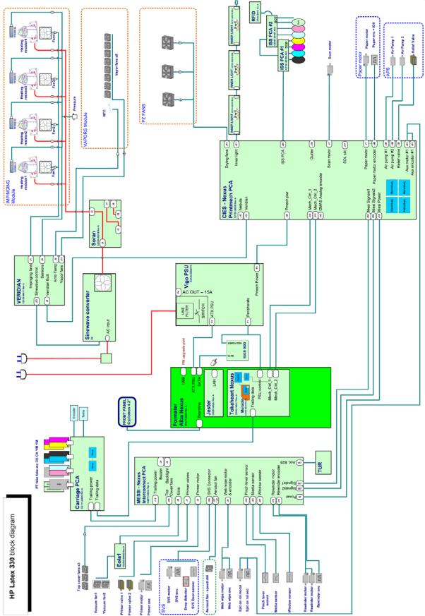
HP Latex 330
4 Chapter 1 Printer systems |
ENWW |
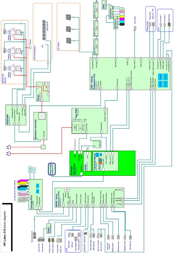
HP Latex 310
ENWW |
Electrical system 5 |
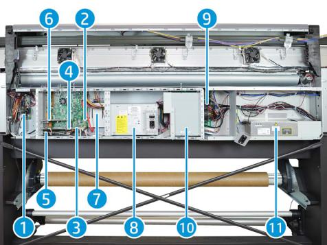
E-Box Components
Description
The E-box contains most of the electronics of the printer.
Components
1.Interconnect PCA
2.Formatter PCA
3.Engine PCA
4.Printer ID PCA
5.OMAS PCA
6.LAN PCA
7.Solid State Disk Drive (SSD)
8.Power Supply Unit (Main PSU)
9.Printmech PCA
10.Air Curtain and Printzone Heaters control PCA
11.Heater Control
Functionality
Interconnect PCA
The Interconnect PCA is an interconnect board with connectors that helps distribute power, and control signals from the Printmech board, to all the elements connected to the right side of the machine, including the following:
6 Chapter 1 Printer systems |
ENWW |

●Take-Up Reel
●Vacuum Fans (passes through; the actual control is inside Eola)
●Valves and Motors for Primer, Rack Engage, SVS, and Aerosol Fan
●Top Cover Fans
●Rewinder Motor
●Pinch Lever, Media and Window Sensors
Formatter PCA
The motherboard of the printer. It is the same type of board as found in a standard computer.
Engine PCA
The main controller of the printer. It is responsible for all the processes performed in real-time, and is the ultimate controller of all electromechanical systems. The Engine PCA controls all substrate path components (Drive Roller, Spindle Motors, OMAS, etc.), and all non-substrate path components (Carriage, Scan Axis Motor, Print Head Cleaning Assembly, Service Station, etc). Attached to this board, is the Printer ID PCA.
Printer ID PCA
Contains printer identification. When replacing the Engine PCA, take care not to lose it.
OMAS PCA (360 only)
Controls the Optical Media Advance Sensor, used to measure substrate advance.
LAN Communication Card
Provides LAN communication.
Solid State Disk Drive (SSD)
Contains:
●The printer firmware
●The operating system
●All calibration values, product number, serial number, and so on. In order to avoid loss in the case of SSD failure, a backup is made in the ISS top board.


 IMPORTANT: In order to prevent any loss of calibration values, do not replace the following at the same time:
●The Hard Disk Drive and the ISS Top Board.
Power Supply Unit (Main PSU)
This PSU delivers power to all the parts of the printer except heater elements. The internal rails are: 5V_sb; 3V3, 5V, 12V, 24V, and 42V.
PrintMech PCA
The PrintMech PCA is mainly used to control the mechatronics of the printer. For routing reasons, only the parts connected to the left side of the printer are connected to this board:
●Scan-Axis Motor
●Substrate-Axis Motor
●Ink Pressurizing Pumps and Valve
ENWW |
Electrical system 7 |

●Ink Collector Sensors
●Ink Supply PCAs Connection
●Inner Light PCAs Connection
●Spit-on-Roll Motor (routed to the right side of the printer)
The remaining functionality implemented in the PrintMech PCA is sent to the right side of the printer through the Mini Interconnect PCA and its three cables (power + data).
Heater Control
Converts the input voltage from the mains to a voltage in the output that is controlled by the Curing Control PCA, and depends on the quantity of power required for impinging.
The converter has three cables: one power cable for the input, one for output, and finally the control cable. The control part of the converter that interfaces with the Curing Control PCA is powered at 24 V.
There are three LEDs: Status (off or fault), PWM (if power is being delivered to the output), and ACOK (if Vin is in range).
Air Curtain and Printzone Heaters control PCA
Controls the Air curtain and Printzone Heaters. For further details refer to: Heating-System Electronics on page 11.
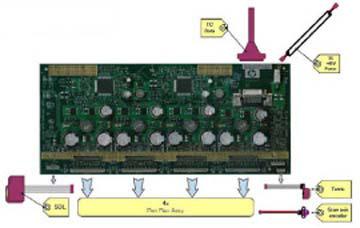
Carriage Electronics
Description
The carriage contains electronics for controlling and firing printheads. It also contains electronics for controlling the external sensors (SOL and Tetris) and the scan-axis encoder.
The electronics of the carriage receive power and data from the trailing cables, which include both power (+42V) and data (LVDS) cables. The power cable connects the carriage with the Mini interconnect board, and the data cable connects the carriage with the engine PCA.
Components
Carriage PCA
The carriage PCA contains electronics that control how and when the ink is dropped from each printhead. It receives information from the sensors.
8 Chapter 1 Printer systems |
ENWW |
SOL Spectrophotometer (HP Latex 360)
The SOL is a color sensor located on the left side of the carriage. The main function of the SOL is to measure color samples printed on the loaded substrate, and then placed in the print platen zone.
Before taking any color measurement, the SOL must be initialized. The SOL initialization process takes approximately 7 minutes. This process consists of three steps:
●Sensor switch on
●Sensor warm up
●Sensor calibration
When the initialization process has finished, the shutter opens automatically and the carriage is moved along the scan axis to place the SOL on top of each sample and take a color measurement. After the measurements, the shutter is closed, and the sensor is switched off.
Tetris
The Tetris is used to align the printheads, and to locate the edges of the substrate and measure its size. The alignment procedure consists of a series of patterns first printed, then scanned using the Tetris, and finally an internal process is used to correct the timing of when and where the nozzles of the printheads fire, and detect any possible nozzle-out issues.
Scan-axis encoder
The line encoder is located on the carriage; it measures and counts the movements of the scan axis. An optical, infrared wavelength encoder is used: the same type of encoder used in most of the HP large-format printers. The encoder signal is converted to LVDS logic levels, and directly routed through the data TC.
Printhead flex
To connect the carriage to the printheads, a delicate flexible circuit with small golden dimples is used. Printheads are inserted into unique slots and a spring-loaded mechanism pushes the electrical contacts of the printheads into the printhead flex, which subsequently connects the printhead to the carriage electronics. Printhead flexes are the most delicate and sensitive part of the carriage. If the printheads are inserted with too much force, or they are misaligned, they can easily be damaged.
Ink Supply Station (ISS) Electronics
Description
There are two ISS PCAs (as in the DJ L25500/L26500 printers).
ENWW |
Electrical system 9 |
Components
Top and bottom ISS PCAs
The ISS electronics are powered from a +12 V line coming from the PrintMech, and a linear regulator on the ISS PCAs generates the +5 V used to power all the devices on the board.
The ISS PCAs are two electronic PCAs located at the rear of the Ink Supply Station. The ISS PCAs provide the following:
●Ink-Supply presence detection
●Ink-Cartridge broken-bag detection
●Ink-Supply smart-chip interface
●Air-Pressure measurement and air-pump shutdown
●Humidity and temperature measurements
●System back-up EEPROM
Below is a picture showing the connections and components located at the rear of the ISS.
Marking |
Description |
|
|
A |
ISS Top PCA |
|
|
B |
ISS Lower PCA |
|
|
C |
Cable: ISS Top PCA to ISS Lower PCA |
|
|
D |
Cable: ISS Top PCA to PrintMech PCA (blue) |
|
|
E |
Cables (6): ISS PCAs (Top and Lower) to Ink Cartridge and PIP |
|
|
F |
ISS grounding cable |
|
|
G |
PIP sensor (6) |
|
|
10 Chapter 1 Printer systems |
ENWW |
Both top and bottom ISS PCAs share the same PCB; the only difference between them is that the bottom PCA is a simplification of the top PCA. The top PCA contains these additional parts:
●EEPROM
●Connection from the PrintMech PCA
●Air pressure sensor
●Temperature and humidity sensors
Both PCAs are connected through an 8-pin connector. The second ISS connector is connected to the PrintMech PCA in a daisy-chained connection, the first ISS board by means of this 8-pin connector.
Vacuum-Fan Electronics
Description
There is one EOLA PCA to control two different brushless blowers generating the required vacuum to hold the substrate. This PCA is connected to the Mini interconnect PCA (right side).
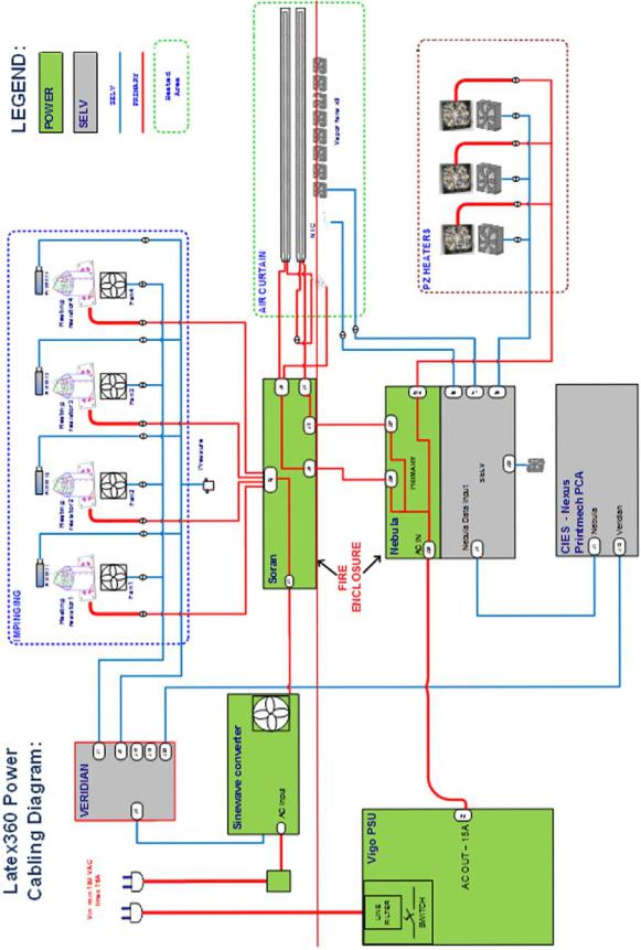
Heating-System Electronics
Description
In the Latex 360 Power, power is delivered to 3 subsystems:
●Impinging (Drying and curing): Controlled through Curing Control PCA
●Air curtain: Controlled through Air Curtain and Printzone Heaters Control PCA
●Print zone heating: Controlled through Air Curtain and Printzone Heaters Control PCA
WARNING! The PRI (POWER) area is not isolated, and there is an electrical shock hazard. The PCA is connected directly to the AC mains input. The power cords should be disconnected before manipulating the power elements.
The following diagrams show configuration, the Primary area, and its connection:
ENWW |
Electrical system 11 |
Components
Air Curtain and Printzone Heaters Control PCA:
12 Chapter 1 Printer systems |
ENWW |
The Air Curtain and Printzone Heaters Control PCA is only present in Latex 360 printers, and is placed inside the EEbox. The Air Curtain and Printzone Heaters Control is the PCA that controls the power delivered to the air curtain resistors and the printzone heaters. The AC power input comes from the Main PSU, but there is a pass through from the input power plug to the PCA AC input. The PCA has a primary non-isolated area, and a SELV isolated area. The power available is balanced between both subsystems based on burst control, the control is provided from the same PCA. The Air Curtain and Printzone Heaters Control also controls both subsystems' fans; the ambient temperature sensor, and the box fan installed for cooling the PCA.
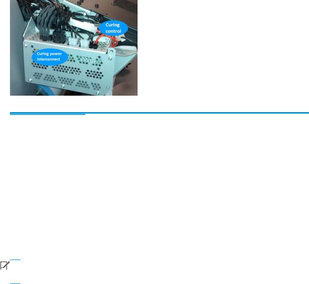
Curing Control PCA:
The Curing Control PCA is placed at the impinging bracket on its left side and executes the servo that applies the power to the impinging module. The Curing Control PCA is present in all three SKUs; In the Latex 360 printer it controls the impinging sensors (Temperature and pressure) and the Heater Control, and in the Latex 330 & Latex 310 printers, it controls the air curtain fans, and reads the ambient temperature sensor. The Curing Control PCA has no power (PRI) lines.
Curing Power Interconnect:
The Curing Power Interconnect PCA is placed just above the Curing Control PCA. Both PCAs are housed in the same fire proof box. The Curing Power Interconnect PCA is connected to power lines and provides the interconnection interface for the curing module, and for the air curtain resistors (Latex 360 only). The Curing Power Interconnect PCA is present in all three SKUs.
Table 1-1 Connection differences between SKUs in the Heating System:
|
HP Latex 360 |
HP Latex 330 |
HP Latex 310 |
|
|
|
|
Ambient temp. sensor |
Air Curtain and Printzone |
Curing Control |
Curing Control |
|
Heaters Control |
|
|
|
|
|
|
Printzone fans |
Air Curtain and Printzone |
Printmech |
Printmech |
|
Heaters Control |
|
|
|
|
|
|
Air curtain fans |
Air Curtain and Printzone |
Curing Control |
Curing Control |
|
Heaters Control |
|
|
|
|
|
|
Air curtain resistors |
Air Curtain and Printzone |
x |
x |
|
Heaters Control/Curing Power |
|
|
|
Interconnect |
|
|
|
|
|
|
Printzone resistors |
Air Curtain and Printzone |
x |
x |
|
Heaters Control |
|
|
|
|
|
|
Electrical configuration


 NOTE: An electrician is required for the setup and configuration of the electrical system used to power the printer. Make sure that your electrician is appropriately certified according to local regulations, and supplied with all the information regarding the electrical configuration.
ENWW |
Electrical system 13 |

Your printer requires the following electrical components to be supplied and installed by the customer, according to the Electrical Code requirements of the local jurisdiction of the country where the equipment is installed.
Single-phase power
Table 1-2 Single-phase line specifications:
|
HP Latex 360 |
HP Latex 330 |
HP Latex 310 |
|||
|
|
|
|
|
|
|
|
Printer |
Curing |
Printer |
Curing |
Printer |
Curing |
|
|
|
|
|
|
|
Number of |
|
2 |
|
2 |
|
2 |
power cords |
|
|
|
|
|
|
|
|
|
|
|
||
Input voltage |
|
|
~200-240 V +-10% (two wires and protective earth) |
|
||
|
|
|
|
|
|
|
Input frequency |
|
|
|
50 / 60 Hz |
|
|
|
|
|
|
|
|
|
Maximum load |
16 A |
16 A |
3 A |
16 A |
3 A |
13 A |
current (per |
|
|
|
|
|
|
power cord) |
|
|
|
|
|
|
|
|
|
|
|
|
|
Power |
2.5 kW |
2.1 kW |
200 W |
2.4 kW |
200 W |
2.0 kW |
consumption per |
|
|
|
|
|
|
power cord in |
|
|
|
|
|
|
printing mode |
|
|
|
|
|
|
|
|
|
|
|
|
|
Power |
|
85 W |
|
72 W |
|
70 W |
consumption in |
|
|
|
|
|
|
ready mode |
|
|
|
|
|
|
|
|
|
|
|
|
|
Circuit breakers


 NOTE: The circuit breakers must meet the requirements of the printer and be in accordance with the Electrical Code requirements of the local jurisdiction of the country where the equipment is installed.
The printer requires two power cords that meet the following requirements.
Table 1-3 Dedicated lines per SKU:
|
HP Latex 360 |
HP Latex 330 |
HP Latex 310 |
|||
|
|
|
|
|
|
|
|
Printer |
Curing |
Printer |
Curing |
Printer |
Curing |
|
|
|
|
|
|
|
Dedicated line |
Yes |
Yes |
Not required. Do |
Yes |
Not required. Do |
Not required. Do |
|
|
|
not overload |
|
not overload |
not overload |
|
|
|
lines. See Table |
|
lines. See Table |
lines. See Table |
|
|
|
2-3 |
|
2-3 |
2-3 |
|
|
|
|
|||
Branch circuit |
|
2 poles, 16 A/20 A according to local laws and printer maximum load current |
|
|||
breaker |
|
|
|
|
|
|
|
|
|
|
|
||
Residual current |
|
Required |
Recommended |
Recommended |
||
circuit breaker |
|
|
|
|
|
|
|
|
2 poles, 30 mA residual, at least 20 A capacity |
|
|||
(1) |
|
|
|
|||
|
|
|
|
|
|
|
(1) Also known as Ground Fault Circuit Interrupter (GFCI)
14 Chapter 1 Printer systems |
ENWW |
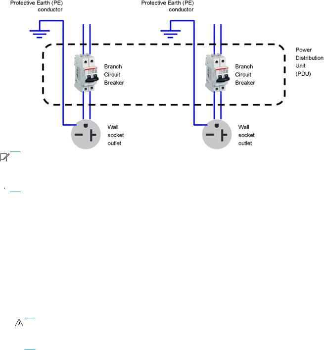
Figure 1-1 Electrical configuration diagram (for reference only)


 NOTE: The Power Distribution Unit (PDU) must be rated to meet the power requirements of the printer, and be in accordance with the Electrical Code requirements of the local jurisdiction of the country where the equipment is installed.
 WARNING! Do not use a power strip (relocatable power tap) to connect both power cords.
Wall receptacles and power cords
Two power cords are provided with your printer, according to the printer's electrical specifications. If those cords do not reach your PDU and/or UPS, a certified electrician must install suitable extension cables on the day of installation.
To make sure you have the right wall socket outlets (wall receptacles) ready for installation, check the following:
1.The wall socket outlets must be suitable for printer input ratings. See Single-phase power on page 14.
2.The wall socket outlets must be suitable for the power cord plug type used in the country of installation. The list shows examples of the power cords and the plugs provided with the printer according to the country. To make sure you have the right wall receptacle, find your country in the appropriate table and check the plug type.
WARNING! Only use the power cord supplied by HP with the printer. Do not use a power strip (relocatable power tap) to connect both power cords. Do not damage, cut, or repair the power cord. With a damaged power cord, there is risk of fire and electric shock. Always replace a damaged power cord with an HP-approved power cord.
Table 1-4 HP Latex 330/360 Printers— Printer power cord specifications:
ENWW |
Electrical system 15 |
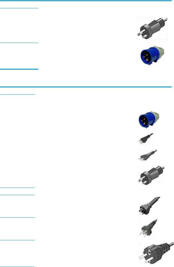
NOTE: For HP Latex 330/360 Printers— Use two power cords from below
Country |
HP Part Number * |
Length |
Plug type |
Plug |
|
|
|
|
|
USA, Canada, Mexico, |
8120-6893 |
4.5 m |
NEMA 6-20P, 240 V, 20 A, |
|
Japan, Philippines, Thailand |
|
|
non-locking |
|
International |
8120-6897 |
4.5 m |
IEC 60309, 240 V, 16 A, 2L |
|
|
|
+PE |
Table 1-5 HP Latex 310 Pinter — Power cord specifications per region:
NOTE: For HP Latex 310 Printers — Use two power cords from below
Country |
HP Part Number * |
Length |
Plug type |
Plug |
|
|
|
|
|
America Region |
|
|
|
|
|
|
|
|
|
Argentina |
8120-6897 |
4.5 m |
IEC 60309, 240V, 16A, |
|
|
|
|
2L+PE |
|
|
|
|
|
|
Brazil |
8121-110 |
2.5 m |
NBR 14136 |
|
|
|
|
|
|
Chile, Uruguay |
8121-0923 |
2.5 m |
CEI 23-50 |
|
|
|
|
|
|
USA, Canada, Mexico |
8120-6360 |
2.5 m |
NEMA 6-20P, 240 V, 20 |
|
|
|
|
A, non-locking |
|
Asia Pacific and Japan Region
Australia/New Zealand |
8120-6351 |
2.5 m |
AS/NZS 3112-3 (15A) |
China |
8121-0924 |
2.5 m |
GB 1002 (16A) |
Korea, Indonesia |
8120-6352 |
2.5 m |
CEE 7-VII |
16 Chapter 1 Printer systems |
ENWW |

NOTE: For HP Latex 310 Printers — Use two power cords from below
Country |
HP Part Number * |
Length |
Plug type |
Plug |
|
|
|
|
|
India |
8121-1074 |
2.5 m |
IS 1293 |
|
|
|
|
|
|
Taiwan |
8121-1033 |
4.5 m |
CNS 690 |
|
|
|
|
|
|
Hong Kong, Singapore |
8120-6898 |
4.5 m |
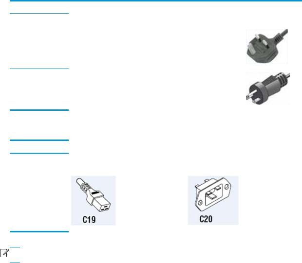
BS 1363/A (13A fused) |
|
|
|
|
|
|
Japan, Philippines, |
8120-6360 |
2.5 m |
NEMA 6-20P, 240 V, 20 |
|
Thailand |
|
|
A, non-locking |
|
|
|
|
|
|
Europe, Middle East and Africa Region |
|
|
|
|
|
|
|
|
|
Europe Russia |
8120-6352 |
2.5 m |
CEE 7-VII |
|
|
|
|
|
|
Denmark |
8121-1077 |
2.5 m |
DK 2-5A |
|
|
|
|
|
|
Israel |
8121-1010 |
2.5 m |
SI 32 |
|
|
|
|
|
|
South Africa |
8121-0915 |
2.5 m |
SABS 164 |
|
|
|
|
|
|
Switzerland, |
8120-6897 |
4.5 m |
IEC 60309, 240 V, 16 A, |
|
Liechtenstein |
|
|
2L+PE |
|
|
|
|
|
|
ENWW |
Electrical system 17 |
NOTE: For HP Latex 310 Printers — Use two power cords from below
Country |
HP Part Number * |
Length |
Plug type |
Plug |
|
|
|
|
|
U.K. |
8120-6898 |
4.5 m |
BS 1363/A (13A fused) |
|
Middle East |
8120-6360 |
2.5 m |
NEMA 6-20P, 240 V, 20 |
|
|
|
A, non-locking |
Table 1-6 Appliance coupler (printer connection):
Country |
Appliance coupler (power cable) |
Appliance coupler inlet (printer) |
All |
Detachable terminal as per IEC60320-1 C19 |
|
(squared type) |
Detachable inlet as per IEC60320-1 C20 (squared type)


 NOTE: Place the wall receptacle close enough to the printer so the plug can be plugged and unplugged easily.
Electronic Cables Routing
This section can be used as a reference section, to check the original routing of the cables
18 Chapter 1 Printer systems |
ENWW |

Rear Service Station Cables Routing
Interconnect PCA Cables Routing
ENWW |
Electrical system 19 |
Loading...