


HPWT-DL00
Table of contents
 Loading...
HP HPWT-DL00, HPWT-MH00, HPWT-ML00, HPWA-DH00, HPWA-DL00 Datasheet
...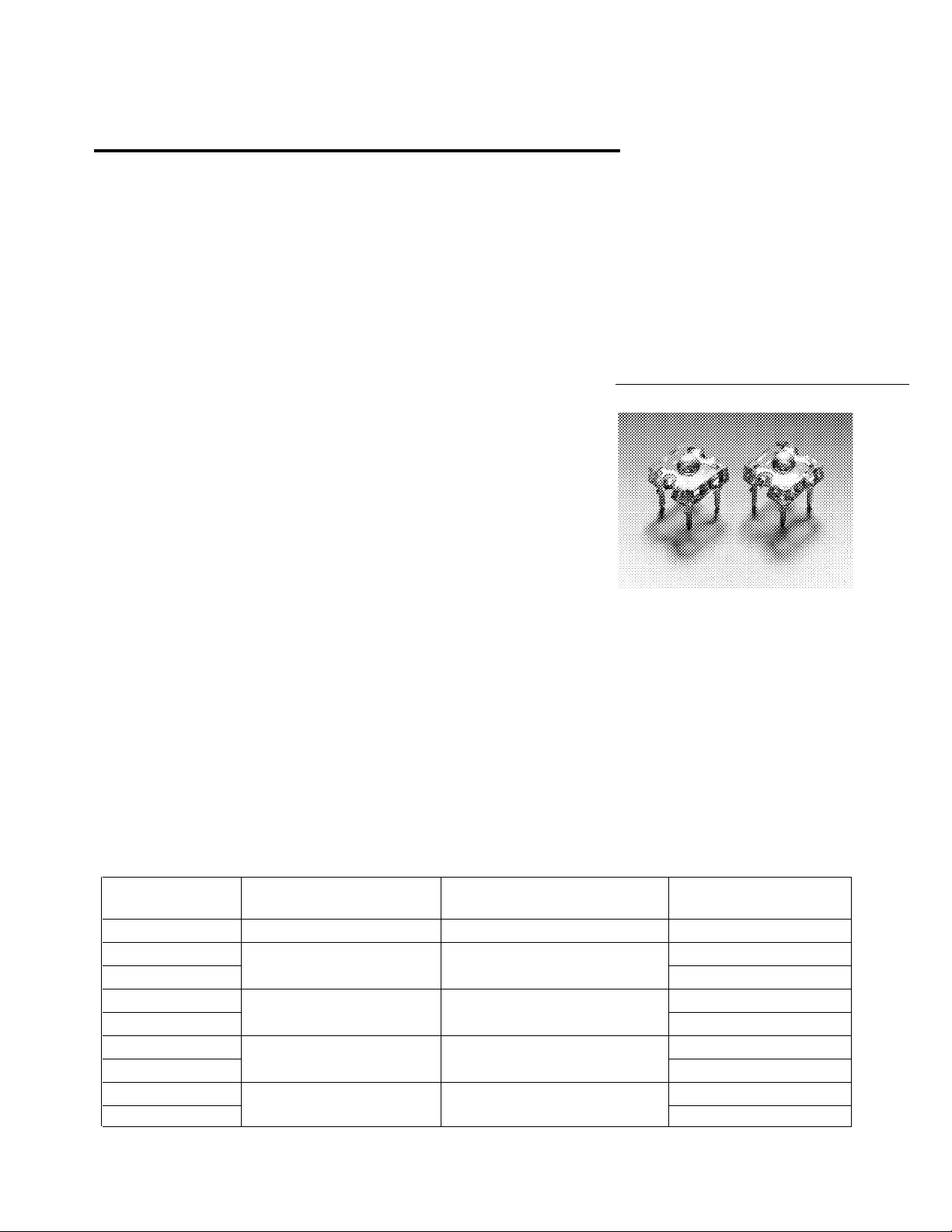
Super Flux LEDs
Technical Data
H
SunPower Series
HPWA-MH00
HPWA-DH00
HPWA-ML00
HPWA-DL00
HPWR-M300
HPWT-MH00
HPWT-DH00
HPWT-ML00
HPWT-DL00
Benefits
• Fewer LEDs Required
• Lowers Total System Cost
Features
• High Flux Output
• Designed for High Current
Operation
• Low Thermal Resistance
• Low Profile
• Meets SAE/ECE/JIS
Automotive Color
Requirements
• Packaged in Tubes for Use
with Automatic Pick and
Place Equipment
Applications
• Automotive Exterior
Lighting
• Moving Message Panels
• Small and Large Area
Displays
• Backlighting
Description
This revolutionary package design
allows the lighting designer to
reduce the number of LEDs
required and provide a more
uniform and unique illuminated
appearance than with existing
LED solutions. This is possible
through the package’s efficient
optical design and high-current
capabilities. The low profile
package can be easily coupled to
reflectors or lenses to efficiently
distribute light and provide the
desired illuminated appearance.
This product family employs red,
red-orange, and amber LED
materials, which allow designers
to match the color of popular
lighting applications, such as
automotive tail, stop, and turn
signal lamps, and area displays.
Included in this family is the
world’s brightest amber LED
material, which is ideal for area
displays and general backlighting
applications.
Device Selection Guide
Total Flux Viewing Angle
Part Number LED Color φv (mlm) @ 70 mA
HPWR-M300 TS AlGaAs Red 800 90
HPWA-MH00 AS AlInGaP Red-Orange 1250 90
HPWA-DH00 60
HPWA-ML00 AS AlInGaP Amber 1250 90
HPWA-DL00 60
HPWT-MH00 TS AlInGaP Red-Orange 2500 70
HPWT-DH00 40
HPWT-ML00 TS AlInGaP Amber 2500 70
HPWT-DL00 40
Notes:
1. φV is the total luminous flux output as measured with an integrating sphere.
2. θ1/2 is the off axis angle from optical centerline where the luminous intensity is 1/2 the on-axis value.
5964-2064E
[1]
Typ. 2θ1/2 (Degrees) Typ.
1-25
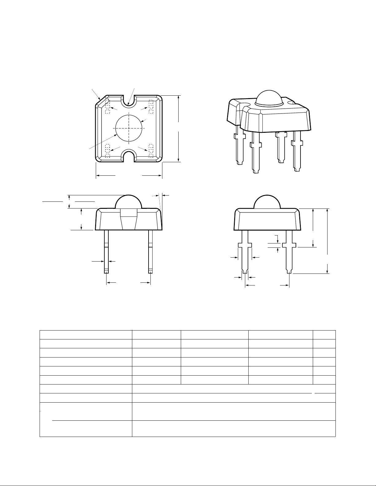
Outline Drawing
CHAMFER 1.25 x 1.25
(0.049 x 0.049)
2 x R
(0.027 ± 0.008)
C C
CATHODE
0.69 ± 0.20
7.62 ± 0.50
(0.300 ± 0.020)
MX00
1.50 (0.059)
(0.016 ± 0.008)
3.00 ± 0.20
φ
(0.118 ± 0.008)
OR
1.90 (0.075)
2.50 ± 0.50
(0.098 ± 0.020)
0.40 ± 0.20
ANODE
A A
7.62 ± 0.50
(0.300 ± 0.020)
DX00
TYP.
5.08 ± 0.30
NOTES:
1. DIMENSIONS ARE IN MILLIMETERS (INCHES).
2. DIMENSIONS WITHOUT TOLERANCES ARE NOMINAL.
3. CATHODE LEADS ARE INDICATED WITH A "C" AND
ANODE LEADS ARE INDICATED WITH AN "A".
(0.200 ± 0.012)
5.0° TYP.
1.55 ± 0.20
(0.061 ± 0.008)
0.76 ± 0.10
(0.030 ± 0.004)
TYP.
TYP.
0.50 (0.020)
TYP.
5.08 ± 0.20
(0.200 ± 0.008)
4.40 ± 0.20
(0.173 ± 0.008)
7.50 ± 0.20
(0.295 ± 0.008)
Absolute Maximum Ratings at T
= 25°C
A
Parameter HPWR-M300 HPWA-MX00/DX00 HPWT-MX00/DX00 Units
DC Forward Current
[1]
70 70
[2,3]
70
[2,3]
Power Dissipation 161 147 193 mW
Reverse Voltage (IR = 100 µA) 10 10 10 V
Operating Temperature Range -40 to +100 -40 to +100 -40 to +100 °C
Storage Temperature -55 to +100 -55 to +100 -55 to +100 °C
High Temperature Chamber 125°C, 2 hrs. max.
LED Junction Temperature 125°C
Solder Conditions
Preheat Temperature 100° C
Solder Temperature 260°C for 5 seconds
[1.5 mm (0.06 in.) below seating plane]
Notes:
1. Derate linearly as shown in Figure 4a and 4b.
2. Drive Currents between 10 mA and 30 mA are recommended for best long term performance.
3. Operation at currents below 10 mA is not recommended, please contact your Hewlett-Packard sales representative.
1-26
mA
Loading...