HP INA-52063-TR1, INA-52063-BLK Datasheet

1.5 GHz Low Noise Silicon
MMIC Amplifier
Technical Data
INA-52063
Features
•Ultra-Miniature Package
•Single 5 V Supply (30 mA)
•22 dB Gain
•8 dBm P1dB
•Unconditionally Stable
Applications
•Amplifier for Cellular, Cordless, Special Mobile Radio, PCS, ISM, Wireless LAN, DBS, TVRO, and TV Tuner Applications
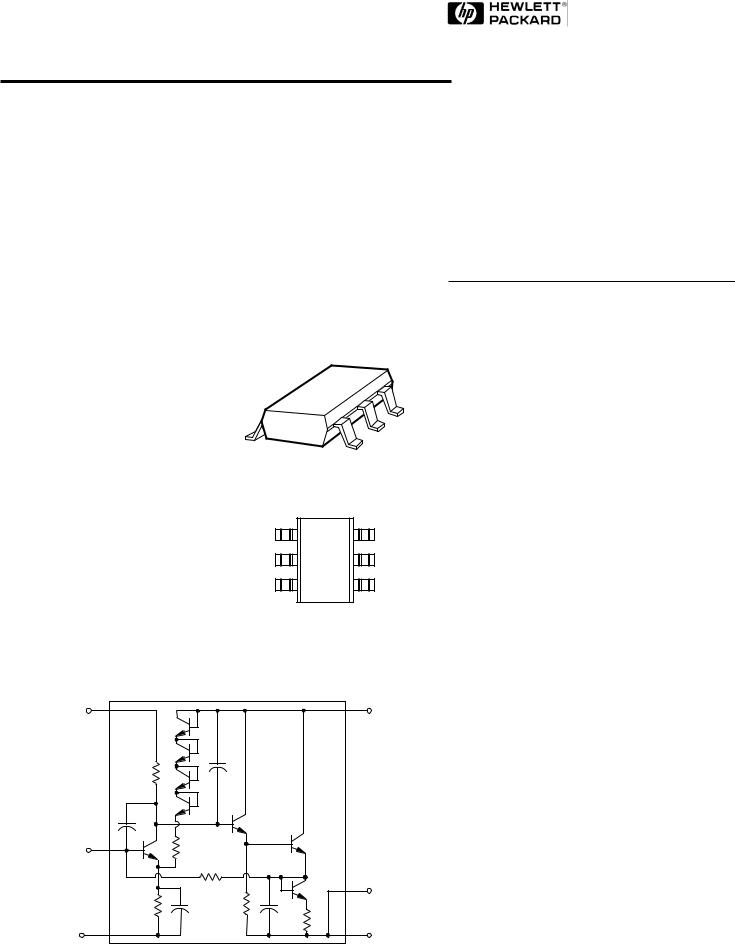
Surface Mount SOT-363
(SC-70) Package
Pin Connections and
Package Marking
GND 2 |
52 |
6 |
OUTPUT |
|
and VCC |
||||
GND |
1 |
5 |
GND 3 |
|
INPUT |
3 |
|
4 |
VCC |
Note: Package marking provides orientation and identification.
Equivalent Circuit
(Simplified) |
|
VCC |
RF |
|
OUTPUT |
|
& VCC |
RF |
|
INPUT |
|
|
GROUND 1 |
GROUND 2 |
GROUND 3 |
5965-9681E |
6-156 |
Description
Hewlett-Packard’s INA-52063 is a Silicon monolithic amplifier that offers excellent gain and power output for applications to
1.5 GHz. Packaged in an ultraminiature SOT-363 package, it requires half the board space of a SOT-143 package.
The INA-52063 is fabricated using
HP’s 30 GHz fMAX ISOSATTM Silicon bipolar process which
uses nitride self-alignment submicrometer lithography, trench isolation, ion implantation, gold metallization, and polyimide intermetal dielectric and scratch protection to achieve superior performance, uniformity, and reliability.

Absolute Maximum Ratings
|
|
|
Absolute |
Symbol |
Parameter |
Units |
Maximum[1] |
VCC |
Supply Voltage, to Ground |
V |
12 |
Pin |
CW RF Input Power |
dBm |
+13 |
Tj |
Junction Temperature |
°C |
150 |
TSTG |
Storage Temperature |
°C |
-65 to 150 |
Thermal Resistance[2]:
θj-c =170°C/W
Notes:
1.Operation of this device above any one of these limits may cause permanent damage.
2.TC = 25°C (TC is defined to be the temperature at the package pins where
contact is made to the circuit board)
INA-52063 Electrical Specifications, TC = 25°C, ZO = 50 Ω, VCC = 5 V, unless noted
Symbol |
Parameters and Test Conditions |
|
Units |
Min. |
Typ. |
Max. |
|
|
|
|
|
|
|
G |
PowerGain(|S |2) |
f = 900 MHz |
dB |
20 |
22 |
|
p |
21 |
|
|
|
|
|
NF |
Noise Figure |
f = 900 MHz |
dB |
|
4.0 |
|
|
|
|
|
|
|
|
P1dB |
Output Power at 1 dB Gain Compression |
f = 900 MHz |
dBm |
|
+8 |
|
IP3 |
Third Order Intercept Point |
f = 900 MHz |
dBm |
|
+20 |
|
IP3 |
Third Order Intercept Point |
f=2100MHz |
dBm |
|
+15 |
|
VSWR |
Input VSWR |
f = 900 MHz |
|
|
1.4 |
|
|
|
|
|
|
|
|
|
Output VSWR |
f = 900 MHz |
|
|
1.3 |
|
|
|
|
|
|||
|
|
|
|
|
|
|
ICC |
Device Current |
|
mA |
|
30 |
38 |
ιd |
Group Delay |
f = 900 MHz |
ps |
|
238 |
|
6-157

INA-52063 Typical Performance, TC = 25°C, ZO = 50 Ω, VCC = 5 V, unless noted
|
24.0 |
|
|
|
|
|
|
|
|
|
|
|
|
|
|
|
23.0 |
|
|
|
|
|
|
|
|
|
|
5.5 V |
|
|
|
|
|
|
|
|
|
|
|
|
|
|
5.0 V |
|
|
||
|
|
|
|
|
|
|
|
|
|
|
|
|
|||
|
22.0 |
|
|
|
|
|
|
|
|
|
|
4.5 V |
|
|
|
(dB) |
21.0 |
|
|
|
|
|
|
|
|
|
|
|
|
|
|
|
|
|
|
|
|
|
|
|
|
|
|
|
|
||
20.0 |
|
|
|
|
|
|
|
|
|
|
|
|
|
|
|
GAIN |
|
|
|
|
|
|
|
|
|
|
|
|
|
|
|
19.0 |
|
|
|
|
|
|
|
|
|
|
|
|
|
|
|
|
|
|
|
|
|
|
|
|
|
|
|
|
|
|
|
|
18.0 |
|
|
|
|
|
|
|
|
|
|
|
|
|
|
|
|
|
|
|
|
|
|
|
|
|
|
|
|
|
|
|
17.0 |
|
|
|
|
|
|
|
|
|
|
|
|
|
|
|
|
|
|
|
|
|
|
|
|
|
|
|
|
|
|
|
16.0 |
|
|
|
|
|
|
|
|
|
|
|
|
|
|
|
|
|
|
|
|
|
|
|
|
|
|
|
|
|
|
|
15.0 |
|
|
|
|
|
|
|
|
|
|
|
|
|
|
|
0.05 |
0.65 |
1.25 |
1.85 |
2.45 |
||||||||||
FREQUENCY (GHz)
NOISE FIGURE (dB)
6.0
 5.5 V 5.5
 5.0 V
5.0 V  4.5 V
4.5 V
5.0
4.5
4.0
3.5
0.09 0.2 0.5 0.8 1.1 1.4 1.7 2.0 2.3 2.6
FREQUENCY (GHz)
P1dB (dBm)
12.0
11.0
10.0
9.0
8.0
7.0
6.0
5.0
4.0
 5.5 V 5.0 V
3.0 
 4.5 V
4.5 V
2.0
0.050.30 0.60 1.20 1.80 2.40
FREQUENCY (GHz)
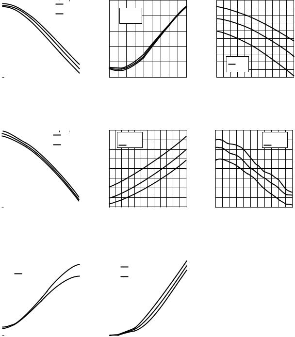
Figure 1. Gain vs. Frequency and Voltage.
Figure 2. Noise Figure vs. Frequency and Voltage.
Figure 3. Output Power for 1 dB Gain Compression vs. Frequency and Voltage.
|
24.0 |
|
|
|
|
|
|
|
|
|
|
|
|
|
|
23.0 |
|
|
|
|
|
|
|
|
-40 °C |
|
|
|
|
|
|
|
|
|
|
|
|
|
+25 °C |
|
|
|||
|
|
|
|
|
|
|
|
|
|
|
||||
|
22.0 |
|
|
|
|
|
|
|
|
+85 °C |
|
|
||
(dB) |
21.0 |
|
|
|
|
|
|
|
|
|
|
|
|
|
|
|
|
|
|
|
|
|
|
|
|
|
|
||
20.0 |
|
|
|
|
|
|
|
|
|
|
|
|
|
|
GAIN |
|
|
|
|
|
|
|
|
|
|
|
|
|
|
19.0 |
|
|
|
|
|
|
|
|
|
|
|
|
|
|
|
|
|
|
|
|
|
|
|
|
|
|
|
|
|
|
18.0 |
|
|
|
|
|
|
|
|
|
|
|
|
|
|
|
|
|
|
|
|
|
|
|
|
|
|
|
|
|
17.0 |
|
|
|
|
|
|
|
|
|
|
|
|
|
|
|
|
|
|
|
|
|
|
|
|
|
|
|
|
|
16.0 |
|
|
|
|
|
|
|
|
|
|
|
|
|
|
|
|
|
|
|
|
|
|
|
|
|
|
|
|
|
15.0 |
|
|
|
|
|
|
|
|
|
|
|
|
|
|
0.05 |
0.60 |
1.20 |
1.80 |
|
2.40 |
||||||||
FREQUENCY (GHz)
NOISE FIGURE (dB)
7.0
 -40 °C 6.5
 +25 °C +85 °C
6.0
5.5
5.0
4.5
4.0
3.5
3.0
0.05 0.40 0.80 1.20 1.60 2.00 2.40
FREQUENCY (GHz)
P1dB (dBm)
12
 -40 °C 11
 +25 °C +85 °C
10
9
8
7
6
5
4
0.050.30 0.60 1.20 1.80 2.40
FREQUENCY (GHz)
Figure 4. Gain vs. Frequency and Temperature.
|
2.2 |
|
|
|
|
|
|
|
|
|
|
|
|
|
|
|
|
|
|
|
|
|
|
|
|
|
|
|
|
|
2.0 |
|
|
VSWR IN |
|
|
|
||
|
|
|
|
|
|
||||
|
|
|
VSWR OUT |
|
|
|
|||
|
|
|
|
|
|
|
|||
(dB) |
1.8 |
|
|
|
|
|
|
|
|
|
|
|
|
|
|
|
|
||
1.6 |
|
|
|
|
|
|
|
|
|
VSWR |
|
|
|
|
|
|
|
|
|
|
|
|
|
|
|
|
|
||
1.4 |
|
|
|
|
|
|
|
|
|
|
|
|
|
|
|
|
|
|
|
|
1.2 |
|
|
|
|
|
|
|
|
|
|
|
|
|
|
|
|
|
|
|
1.0 |
|
|
|
|
|
|
|
|
|
|
|
|
|
|
|
|
|
|
0.0 |
0.4 |
0.7 |
1.1 |
1.4 |
1.8 |
2.1 |
2.5 |
5 |
0 |
5 |
0 |
5 |
0 |
5 |
0 |
FREQUENCY (GHz)
Figure 7. Input and Output VSWR vs. Frequency.
Figure 5. Noise Figure vs. Frequency and Temperature.
|
60 |
|
|
|
|
|
|
|
|
|
|
|
|
|
|
|
|
|
|
|
|
|
|
|
|
|
|
|
|
|
|
|
|
|
|
|
|
|
|
|
|
|
|
|
|
|
|
|
|
|
|
|
|
|
|
|
|
50 |
|
|
|
|
-40 °C |
|
|
|
|
|
|
|
|
|
|||
|
|
|
|
|
+25 °C |
|
|
|
|
|
|
|
|
|
||||
|
|
|
|
|
|
|
|
|
|
|
|
|
|
|||||
|
|
|
|
|
|
+85 °C |
|
|
|
|
|
|
|
|
|
|||
(mA) |
40 |
|
|
|
|
|
|
|
|
|
|
|
|
|
|
|
|
|
|
|
|
|
|
|
|
|
|
|
|
|
|
|
|
|
|
||
30 |
|
|
|
|
|
|
|
|
|
|
|
|
|
|
|
|
|
|
|
|
|
|
|
|
|
|
|
|
|
|
|
|
|
|
|
||
CC |
|
|
|
|
|
|
|
|
|
|
|
|
|
|
|
|
|
|
I |
20 |
|
|
|
|
|
|
|
|
|
|
|
|
|
|
|
|
|
|
|
|
|
|
|
|
|
|
|
|
|
|
|
|
|
|
|
|
|
|
|
|
|
|
|
|
|
|
|
|
|
|
|
|
|
|
|
|
10 |
|
|
|
|
|
|
|
|
|
|
|
|
|
|
|
|
|
|
|
|
|
|
|
|
|
|
|
|
|
|
|
|
|
|
|
|
|
0 |
|
|
|
|
|
|
|
|
|
|
|
|
|
|
|
|
|
|
0.0 |
1.0 |
2.0 |
3.0 |
4.0 |
5.0 |
6.0 |
7.0 |
||||||||||
VCC (V)
Figure 8. Supply Current vs. Voltage and Temperature.
Figure 6. Output Power for 1 dB Gain Compression vs. Frequency and Temperature.
6-158
 Loading...