


DMX™ 400/430
Operator’s Manual

HP PCL-4, and HP Laser Jet II are Trademarks of Hewlett Packard Corporation. CG Triumvirate is a trademark of Agfa Corporation.
CG Times, based upon Times New Roman under license from The Monotype Corporation.
plc, is a product of Agfa Corporation.
DMX, SEAQ, and PC Batch are trademarks of Datamax Barcode Products Corporation.
As an Energy Star Partner, Datamax Corporation has determined that this product meets the Energy Star guidelines for energy efficiency.
Firmware (Software) Agreement: The enclosed Firmware (Software) resident in the EPROM’s is owned by Licensor or its suppliers and is licensed for used only on a single printer in the user’s Trade or Business. The User agrees not to, and not to authorize or permit any other person or party to, duplicate or copy the EPROM’s or the information contained in the EPROM’s.
The firmware (Software) is protected by applicable copyright laws and Licensor retains all rights not expressly granted. In no event will Licensor or its suppliers be liable for any damages or loss, including direct, incidental, economic, special, or consequential damages, arising out of the use or inability to use the Firmware (Software).
Information in this document is subject to change without notice and does not represent a commitment on the part of Datamax Barcode Products Corporation. No part of this manual may be reproduced or transmitted in any form or by any means, for any purpose other than the purchaser's personal use, without the expressed written permission of Datamax Corporation.
© Copyright 1997 by Datamax Corporation
7500 Flying Cloud Drive • Suite 655 • Eden Prairie, Minnesota 55344 (612) 946-0026
All rights reserved. Printed in the United States of America.
Part Number: 88-2190-01
Revision: A2
Agency Compliance and Approvals:
UL: UL1950 Information Technology Equipment
CSA: C22.2 No. 950-M89
TUV: EN60950
VDE: Class B Vfg. 243/1991
1.Nur für Gebrauch innerhalb eines Gebäudes geeignet.
2.Bei Gefahr, Kabel aus der Steckdose herausziehen
3.Falls kein Kabel mitgeliefert wurde, bitte Folgendes bei der Anschaffung eines Kabels beachten:
Für 230 Volt (Europa): Benützen Sie ein Kabel, das mit "HAR" markiert ist, bestehend mindestens aus einem H05VV-F Kabel, das mindestens 0,75 Quadratmillimeter Drahtdurchmesser hat; sowie eine IEC320 Steckdose und einen für das Land geeigneten Stecker, 6A, 250 Volt.
1.This unit is intended for indoor use only.
2.Disconnect power supply cord in case of emergency.
3.When power supply cord is not provided; for proper power supply cord selection please see below:
For 230 Volt Operation (Europe): Use a cord set, marked "HAR," consisting of a min H05VV-F cord which has a minimum 0.75 square mm diameter conductors, provided with an IEC 320 receptacle and a male plug for the country of installation rated 6A, 250V
FCC: This device complies with Part 15 of FCC rules.
Note: This equipment has been tested and found to comply with the limits for a Class A digital device, pursuant to Part 15 of the FCC Rules. These limits are designed to provide reasonable protection against harmful interference when the equipment is operated in a commercial environment. This equipment generates, uses, and can radiate radio frequency energy, and if not installed and used in accordance with the instructions in this manual, may cause interference to radio communications. Operation of this equipment in a residential area is likely to cause harmful interference in which case the user will be required to correct the interference at his own expense.
Important Safety Instructions
Your Barcode Printer has been designed to give you many years of safe, reliable service. As with all electrical equipment, there are a few basic precautions you should take to avoid getting hurt or damaging the Printer.
∙Carefully read the installation and operating instructions provided with your Printer.
∙Read and follow all warning instruction labels on the Printer itself.
∙Place the Printer on a flat, firm, solid surface.
∙To protect your Printer from overheating, make sure all openings on the Printer are not blocked.
∙Do not place the Printer on or near a heat source, (i.e., a radiator or heat register).
∙Do not use your Printer near water, or spill liquid of any kind into it.
∙Be certain that your power source matches the rating listed on the back of the Printer. If you are unsure, check with your dealer or with your local power company.
∙Do not place the power cord where it will be walked on. If the power cord becomes damaged or frayed replace it immediately.
∙Do not insert anything into the ventilation slots or openings on the Printer.
∙Only qualified, trained service technicians should attempt to repair your Printer.
♦Contents
♦Getting Started
1.0 |
Introduction ......................................................... |
1 |
|
1.1 |
Unpacking and Inspection .................................... |
1 |
|
1.2 |
Supplies Necessary to Print .................................. |
2 |
|
1.3 |
Location of Parts on your Printer ......................... |
2 |
|
1.4 |
Tear-off Assembly Installation ............................. |
4 |
|
1.5 |
Using the Printer’s Control Panel.......................... |
5 |
|
1.6 |
Using Print Media................................................. |
8 |
|
|
1.6.1 |
Label Loading Instructions ...................... |
9 |
|
1.6.2 |
Adjusting Printhead Pressure ................ |
10 |
1.7 |
Ribbon Loading ................................................. |
12 |
|
|
1.7.1 Ribbon Loading Instructions ................ |
12 |
|
1.8 |
Using the Printer’s Options................................. |
13 |
|
|
1.8.1 |
Available Modules ................................ |
13 |
|
1.8.2 |
Cutter .................................................... |
14 |
|
1.8.3 |
Peel and Present Mechanism ................. |
14 |
♦ Printing Labels |
|
|
|
2.0 |
Checking Voltage Selection................................ |
15 |
|
2.1 |
Power-up Self-Test ............................................ |
15 |
|
2.2 |
Interfacing to the Printer..................................... |
18 |
|
2.3 |
Sample Installation............................................. |
19 |
|
2.4 |
Switch Settings................................................... |
21 |
|
|
2.4.1 |
Setting the Baud Rate ............................ |
22 |
|
2.4.1 |
Other Switches ...................................... |
23 |
♦ Creating Labels Using Internal Batch Software |
|
||
3.0 |
Introduction ....................................................... |
25 |
|
3.1 |
The Printer used with a LINK CRT .................... |
26 |
|
3.2 |
Formatting and Printing Labels........................... |
29 |
|
3.3 |
Create/Modify Label Screen .............................. |
34 |
|
3.4 |
Print Label Screen ............................................ |
47 |
|
|
3.4.1 |
Printing a Label from Print Label Screen 47 |
|
3.5 |
System Maintenance Screen .............................. |
49 |
|
(Continued)
i
3.6 |
Quick Reference Listing ..................................... |
51 |
|
|
3.6.1 |
Create/Modify Label Commands .......... |
51 |
|
3.6.2 |
Print Parameters (ALT-P)...................... |
52 |
|
3.6.3 |
Special Keys ......................................... |
52 |
♦ Printing Labels |
|
|
|
4.0 |
Introduction ........................................................ |
53 |
|
4.1 |
Programming Commands.................................... |
53 |
|
4.2 |
Programming Examples....................................... |
59 |
|
♦ Troubleshooting |
|
|
|
5.0 |
Introduction ........................................................ |
61 |
|
5.1 |
Controlling Print Quality ..................................... |
62 |
|
5.2 |
Aligning the Printhead......................................... |
63 |
|
|
5.2.1 Direct-Thermal Stock .......................... |
63 |
|
|
5.2.2 Tag Stock or Stiff Media ...................... |
63 |
|
|
5.2.3 Mechanical Adjustments....................... |
64 |
|
5.3 |
Printhead Alignment Procedure........................... |
65 |
|
|
5.3.1 Label Stock Tracking Adjustment ......... |
65 |
|
|
5.3.2 Ribbon Feed and Tracking Adjustments65 |
||
|
5.3.3 Fine Printhead Adjustment.................... |
67 |
|
5.4 |
Adjusting Printhead Pressure and Support .......... |
67 |
|
5.5 |
Troubleshooting.................................................. |
68 |
|
♦ Maintenance |
|
|
|
6.0 |
Cleaning the Printer............................................. |
73 |
|
6.1 |
Cleaning the Printhead ........................................ |
74 |
|
(Continued)
ii
♦ Appendix A |
|
ASCII Control Code Chart........................................ |
A-1 |
♦ Appendix B |
|
Switch Settings and Cable Interfacing....................... |
B-1 |
♦ Appendix C |
|
Available Fonts and Barcodes ................................... |
C-1 |
♦ Appendix D |
|
Error Codes .............................................................. |
D-1 |
♦ Appendix E |
|
Cable Listings ........................................................... |
E-1 |
♦ Appendix F |
|
Specifications............................................................ |
F-1 |
♦ Appendix G |
|
Warranty Information ............................................... |
G-1 |
iii
iv
♦ Getting Started
1.0 Introduction
The DMX™ 400/430 Label Printer, hereafter referred to as the "Printer", incorporates high-performance/low cost direct thermal and optional thermal-transfer label printing capabilities. The combination of powerful capabilities, easy-to-use features, a contemporary look, and affordable pricing set a new standard for direct-thermal and thermal-transfer label printers in retail, office and industrial applications.This manual provides all the information necessary for the daily operation of your printer.
To create and print labels refer to the instructions included with the software you have chosen or if you wish to write a custom program, visit our website at http//www.datamaxcorp.com for a copy of the Programmer’s Manual (part number 88-2051-01).
1.1Unpacking and Inspection
Inspect the shipping container(s) for damage, if damage is evident contact the carrier to specify the nature and extent of the damage.
Remove the Printer from the packaging material and check the contents of the package. In addition to this manual, the following items should be included:
∙label printer
∙front tear bar assembly
∙special or additional items purchased.
DMX 400/430 Operator’s Manual |
1 |

Getting Started
2 |
DMX 400/430 Operator’s Manual |
Getting Started
1.2Supplies Necessary to Print Labels
In order for the Printer to generate labels you will need the necessary software and media. There are many different types of media and software packages available, therefore it is a good idea to contact your local reseller on which software and media is best suited for your needs.
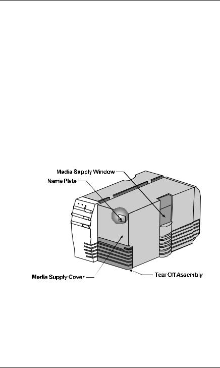
1.3 Location of Parts on your Printer
The following illustrations show the major components of your Printer. Figure 1-1 is the front view of the Printer, Figure 1-2 is the rear view of the Printer, and Figure 1-3 shows the mechanism detail.
In this manual we will refer to the components and connectors depicted in these illustrations.
Figure 1-1 Front View
DMX 400/430 Operator’s Manual |
3 |
 DMX 400, DMX 430 User Manual")
Getting Started
Figure 1-2 Rear View
Figure 1-3 Mechanism Detail
4 |
DMX 400/430 Operator’s Manual |
Getting Started
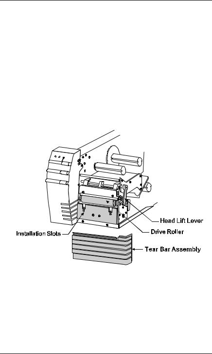
1.4Tear-off Assembly Installation
1.Open the cover.
2.Disengage the Printhead by rotating the Head-Lift Lever counter-clockwise to the ‘up’ position.
3.Fit the Tear-off Assembly to the slots below the drive roller and push it down until it snaps into place.
4.Engage the Printhead by rotating the Head-Lift Lever clockwise, locking into the ‘down’ position.
Figure 1-4 Tear-off Assembly Installation
DMX 400/430 Operator’s Manual |
5 |
Getting Started
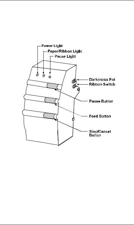
1.5Using the Printer’s Control Panel
The Printer has three operator-accessible buttons, three indicator lights (LEDs), one switch and one POT, (see Figure 1-5). A brief description of the buttons, lights, switch and POT are listed in this section.
Figure 1-5 Buttons and Lights
Power Light: The power light is turned on after the power button on the rear of the Printer is activated.
6 |
DMX 400/430 Operator’s Manual |

Getting Started
Pause Button: This button allows the operator to stop printing a run of labels and then complete the job by pressing the button again. Activation of the button will:
∙Stop the print mechanism when the label printing is complete.
∙Turn on the pause light.
∙Stop the label counter, but maintain the
count balance.
∙ Hold all data in memory.
Pressing the button a second time will:
∙Restart the Printer.
∙Print the balance of labels on the counter unless interrupted.
∙Turn ‘off’ the pause light.
Pause Light: The pause light will turn on if any of the following occurs:
∙The pause button is pressed
∙A print job is canceled with the stop/cancel button.
∙A fault occurs with the cutter or rewind option.
Stop/Cancel Button:This button allows the operator to stop and cancel a run of labels in the process of being produced and continue on to the next run in the Printer’s buffer.
Feed Button: Pressing this button causes the paper to automatically advance to the first print position of the next label. On a new size label, 0 - 2 labels may feed before registration occurs.
DMX 400/430 Operator’s Manual |
7 |

Getting Started
Paper/Ribbon |
This light is activated when: |
|
Light: |
∙ |
No label and/or ribbon is detected. |
|
∙ |
The Internal Rewinder (if installed) is not |
|
|
rotating, (i.e., maximum rewind capacity has |
|
|
been reached). |
Ribbon |
For direct-thermal printing, (no ribbon), slide the |
|
Switch: |
switch to the ‘off’ position. For thermal-transfer |
|
|
printing, (ribbon installed), slide the switch to the |
|
|
‘on’ position. |
|
Darkness POT: |
This POT is used to fine adjust the print darkness |
|
|
due to variations in different medias and |
|
|
printheads. |
|
8 |
DMX 400/430 Operator’s Manual |
Getting Started
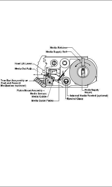
1.6 Using Print Media
Installation
The Printer is designed for easy label stock and ribbon installation. A diagram located under the cover of the Printer shows the feed path for print media. Simply lift the cover of the Printer from the right-hand side for installation instructions.
Figure 1-6 Label Loading Diagram
Labels
The Printer uses labels up to 4.65" (118 mm) wide. The maximum diameter of a roll of labels used in the Printer is 8" (203 mm). If a label is narrower than 3.5" (89 mm) then the Printhead must be adjusted. Please refer to Section 5.4, “Adjusting Printhead Pressure and Support,” for more information.
DMX 400/430 Operator’s Manual |
9 |

Getting Started
1.6.1Label Loading Instructions
1.Disengage the Printhead by rotating the Head-Lift Lever counter-clockwise to the ‘up’ position.
2.Slide the Media Guide to the outer edge and rotate it to the ‘down’ position.
3.Slide the Retainer to the outer edge of the Supply Mount.
4.Place the label roll on the Supply Mount and slide the Retainer firmly against it.
5.Insert the label stock as shown in Figure 1-6.
6.Rotate the Media Guide ‘up’ and slide it to the edge of the media.
7.Engage the Printhead by rotating the Head-Lift Lever clockwise and locking in the ‘down’ position.
8.Set the Media Width Adjustment Cam according to the media width, (see Table 1-1).
Cam Setting |
Media Width |
1 |
Up to 1 " |
2 |
Greater than 1", Up to 2" |
3 |
Greater than 2", Up to 3" |
4 |
Greater than 3", Up to 4.1" |
Table 1-1 Media Width Cam Settings
10 |
DMX 400/430 Operator’s Manual |
Getting Started
1.6.2Adjusting Printhead Pressure
1.Disengage the printhead by rotating the Head-Lift Lever counter-clockwise to the ‘up’ position.
2.Extend the Media Width Adjustment Cam outward from its mounting bracket until the notch on the cam clears the notch on the mounting bracket.
3.With the cam in the extended position, rotate it counterclockwise or clockwise to the desired width setting. The numbered notch on the top right corner of the cam identifies the media width setting. (Figure 1-7 shows the cam being changed from the four position to the one position).
4.When the cam is set to the desired media width setting, return it to its rest position. Make sure that the bracket détente is fully seated in the cams notch.
5.Engage the Printhead by rotating the Head-Lift Lever clockwise to the down position.
Figure 1-7 Adjusting Printhead Pressure
DMX 400/430 Operator’s Manual |
11 |

Getting Started
If the media is not being sensed, try adjusting the label sensor position by turning the adjustment knob for the movable sensor. The gauge behind and below the Printhead can be viewed for making this adjustment. If the label’s edge is not detected within 12" (305 mm) of feeding, the Printer will stop and the paper/ribbon light will remain on. In this case, check the threading of the media around the bottom of the upper and lower Media Guides.
If the paper only feeds forward about 1-inch (26 mm) each time you press the feed button, and does not seem to be stopping on a label edge, the ribbon switch, (shown in Figure 1-5) was probably turned on without thermal-transfer ribbon being installed. Slide this switch toward the front of the Printer for direct-thermal printing. In addition this condition can occur if the media is improperly routed.
12 |
DMX 400/430 Operator’s Manual |
Getting Started
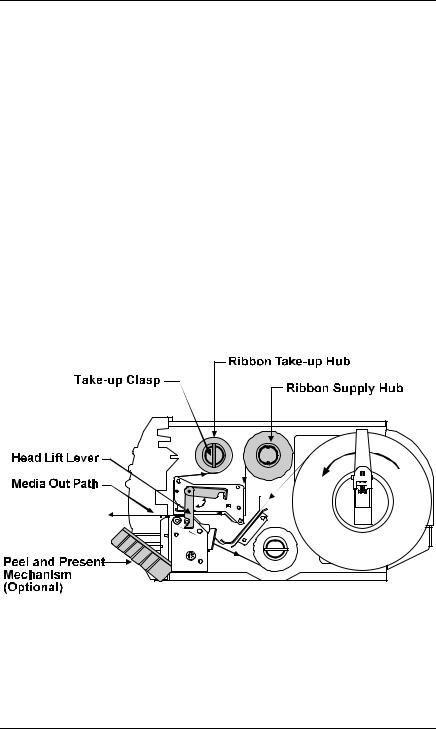
1.7Ribbon Loading
In thermal-transfer mode, ribbons must be attached to the Take-up Hub. The ribbon can be wound directly on to the hub and held with a clasp, or a used ribbon core can be placed on the hub.
1.7.1 Ribbon Loading Instructions
1.Disengage the Printhead by rotating the Head-Lift Lever counterclockwise to the ‘up’ position.
2.Slide the Ribbon on to the Ribbon Supply Hub. Route the ribbon, (see Figure 1-8), and attach the ribbon to the Ribbon Take-up Hub.
3.Engage the Printhead by rotating the Head-Lift Lever clockwise and locking it in the ‘down’ position.
Figure 1-8 Ribbon Loading
DMX 400/430 Operator’s Manual |
13 |

Getting Started
1.8 Using the Printer’s Options
1.8.1Available Modules
The Printer uses Memory modules to expand its built-in capabilities, primarily for the use of storing graphic images and bitmaps of smooth fonts. The Printer has one module slot located on the left side for use with memory module memory cartridges.
Font ROM Modules
Font ROM modules contain additional fonts that extend the capabilities of the internal fonts. Each font ROM module comes with documentation detailing the type and sizes available on the module and the font number of each size used in label formatting. Font ROM modules are programmed at the factory and cannot be modified later for any other purpose.
256K and 512K RAM Modules
RAM modules are the most flexible module option for the Printer. They provide temporary storage of data used in label-format printing. Each module contains 256K of data storage for fonts, graphic images, or label formats.
An additional feature of the 512K RAM module is that the Printer will use a part of its memory to extend the Printer’s bit-mapped label area from: 400: 16" (406 mm) to 28" (711 mm),
430: 16" (406mm) to 22" (558mm).
14 |
DMX 400/430 Operator’s Manual |

Getting Started
256K Flash EEPROM Module
Flash EEPROM modules provide the same features of RAM modules with the added benefit of virtually permanent storage. A write protect button on the Flash EEPROM module can protect data stored on the cartridge from being overwritten or erased.
1.8.2Cutter
The Printer can be ordered with an optional cutter and tray for cutting tags and labels, or the option can be installed at a later date. This option can be easily attached to the Printer and once installed can be enabled by turning ‘on’ switch 8 located on the back of your Printer.
1.8.3Peel and Present Mechanism
The Present Sensor allows the Printer to be configured for ‘one up’ printing. With the sensor installed and enabled, the Printer will not print the next label in its internal buffer until the last label has been removed from the Printer.
DMX 400/430 Operator’s Manual |
15 |

♦ Setting Up Your Printer
2.0 Checking Voltage Selection
The standard Printer is configured for 115 VAC ± 10% singlephase 50/60 Hz with a properly-grounded outlet. A small sticker next to the power cord connection indicates the power requirements.
For international markets, there is a 230 VAC version available. If you are uncertain about the configuration of your Printer, or the outlet you are connecting to, check with a qualified service technician to verify the installation before connecting power.
2.1 Power Up Self-Test
Once labels are installed in the Printer as described in Section 1.6, a Self-Test should be performed. The Printer will power up in the Self-Test Mode when the feed button is pressed as the Printer is being turned on. Initial power up will take approximately 7 seconds. The Printer should be loaded with 4.25" (108 mm) wide stock whenever this test is conducted. The Self-Test prints across the entire width of the Printhead. Expect a brief hesitation of up to 15 seconds before the Self-Test begins to print.
DMX 400/430 Operator’s Manual |
16 |

Setting Up Your Printer
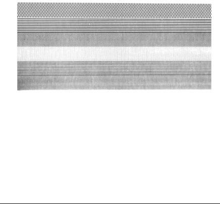
If a label’s edge is not detected within 12" (305 mm) of stock, the Printer will stop feeding labels, (if this occurs, refer to Section 1.6 and reload the media). If a label edge is detected, the Printer will begin to print the Self-Test pattern, see Figure 2-1 or 2-2 (depending on the Printer model) for an example of the Self-Test Label). After the test pattern has successfully printed, the Printer must be turned ‘off’ and then turned ‘on’ again to reset the Printer.
TUE JANUARY 25, 1997 Ø9:29 Ø25 VER: DAØ1 - Ø1.Ø1 12/25/93
ROM CHECKSUM U15 FFFF 47-2014-01A ROM CHECKSUM U19 FFFF 47-2015-01A MCU CHECKSUM U32 GOOD 46-22ØØ-Ø1C SERIAL PORT BAUD IS 96ØØ
MCU INT RAM CHECKS GOOD MCU EXT RAM CHECKS GOOD SYSTEM RAM CHECKS GOOD MODULE CHECKSUM: 7E8B
TRANSFER SWITCH IS OFF |
|
|
|
|
|
|
||
SETUP SW-A |
1 |
2 |
3 |
4 |
5 6 7 |
8 |
|
|
|
|
OFF OFF OFF OFF OFF OFF OFF OFF |
||||||
SETUP SW-B |
1 |
2 |
3 |
4 |
|
|
|
|
|
|
OFF OFF OFF OFF |
|
|
|
|||
ANALOG INPUT VALUES: |
|
|
|
|
|
|
||
PAPER :229 |
EDGE: 173 |
REFL : 195 |
TEMP : Ø62 |
24VOLT : 198 |
||||
POT |
:133 |
TOFA: 153 |
RIBN : Ø27 RWND : 013 |
|
|
|||
INCH COUNTER |
DATE SET: |
|
|
ØØ/ØØ/ØØ |
|
|
||
TOTAL LABEL LENGTH IN INCHES: |
|
44 |
|
|
||||
|
|
|
|
|
|
|
|
|
|
|
|
|
|
|
|
|
|
Figure 2-1 DMX 400 Test Label
DMX 400/430 Operator’s Manual |
17 |
|
|
|
|
|
|
Setting Up Your Printer |
|
|
|||
|
|
|
|
|
|
|
|
||||
|
|
TUE JANUARY |
25, 1997 Ø9:29 Ø25 |
|
|
|
|
||||
|
|
VER: DCØ1 - Ø1.Ø1 12/25/93 |
|
|
|
|
|
||||
|
|
ROM CHECKSUM U12 56B2 47-2Ø25-Ø1A |
|
|
|
||||||
|
|
ROM CHECKSUM U8 1Ø26 47-2Ø26-Ø1A |
|
|
|
||||||
|
|
SYSTEM RAM CHECKS GOOD |
|
|
|
|
|
||||
|
|
SERIAL |
PORT BAUD RATE IS |
96ØØ |
|
|
|
|
|||
|
|
TRANSFER SWITCH I S ON |
|
|
|
|
|
||||
|
|
SETUP SW-A |
1 |
2 |
3 4 |
5 6 |
7 |
8 |
|
|
|
|
|
|
|
OFF OFF OFF OFF OFF OFF OFF OFF |
|
|
|||||
|
|
SETUP SW-B |
1 |
2 |
3 |
4 |
|
|
|
|
|
|
|
|
|
OFF OFF |
OFF |
OFF |
|
|
|
|
|
|
|
ANALOG INPUT |
VALUES: |
|
|
|
|
|
|||
|
|
PAPER :241 |
EDGE: 178 |
REFL : 194 |
TEMP: Ø61 |
24VLT: ØØØ |
|||||
|
|
POT |
:Ø78 |
|
TOFA: 151 |
RIBN : ØØ8 |
RWND: Ø1Ø |
||||
|
|
INCH COUNTER |
DATE SET: |
|
ØØ/ØØ/ØØ |
|
|
||||
|
|
TOTAL LABEL LENGTH IN INCHES: |
674144 |
|
|
||||||
|
|
|
|
|
|
|
|
|
|
|
|
|
|
|
|
|
|
|
|
|
|
|
|
|
|
|
|
|
|
|
|
|
|
|
|
Figure 2-2 DMX 430 Test Label
18 |
DMX 400/430 Operator’s Manual |

Setting Up Your Printer
2.2 Interfacing to the Printer
Depending on your application, the Printer can be set up in different ways. Table 2-1 lists the interface cables that should be used for each situation. If your application is not listed below, refer to Appendix E which contains interface cable information necessary to connect the Printer to virtually any ASCII device.
Part Number |
Description |
556000 |
Printer to CRT Terminal (DB25P) |
|
RS-232C |
556001 |
Printer to PC 9 Pin (DB9S) RS- |
|
232C |
556002 |
Printer to PC 25 Pin (DB25S) RS- |
|
232C |
899516 |
Printer to PC Parallel Port |
|
(DB25P) |
Table 2-1 Interface Cables
For most applications, the interface between the Printer and host device will be RS-232C. The cable necessary to connect the Printer to the host will be either a straight cable or a null-modem cable. This cable connects the DB-25 connector labeled ‘Serial Port’ on the back of the Printer to the serial data connector on the host device.
The pin configuration of the Printer for most descriptions of the RS232C interface on a DB-25 connector is DTE (Data Terminal Equipment). Pin 2 is transmit, pin 3 is receive and pin 7 is ground.
The Printer supports both Xon/Xoff and CTS/DTR handshaking. Whenever the Printer is interfaced in a mode that does not use the CTS/DTR pins, a jumper should be placed on the PC side of the cable between pins 4 and 5 (CTS/RTS) to bypass the operation of those control lines. A custom cable must be obtained for this purpose.
DMX 400/430 Operator’s Manual |
19 |

Setting Up Your Printer
For connection to most host systems, Xon/Xoff handshaking reduces the number of wires necessary in the interface cable. For interfacing RS-422 devices, the Xon/Xoff handshake is the only appropriate method.
2.3 Sample Installations
In this section, four typical installations are reviewed, CRT terminal, PC, minicomputer, and mainframe computer. Interface cable listings for similar installations are listed in Appendix E.
CRT Connection
A typical application for a CRT-based system is generating and printing labels that are stored on an optional Flash Module. First, connect the Printer to the CRT with the cable number 556000 and turn on switch 7 at the rear of the Printer. Next, plug the Module into the slot on the side of the Printer to store label formats on the Module. For a detailed explanation of the operation of this configuration, refer to Chapter 3, ‘Creating Labels Using Internal Batch Software’.
PC Connection
A cable should be selected (refer to Table 2-1), and connected to a PC via a RS-232C port. It is recommended that you use a RS232C port to allow for two-way communication with the Printer. The RS-232C communications port can be connected with one of two possible configurations: a 9 pin cable (part number 556001) or a 25 pin cable (part number 556002).
Note: DB25S (socket/female) connectors on most PCs are normally parallel ports; DB25P and DB9P (pin/male) are normally serial ports.
20 |
DMX 400/430 Operator’s Manual |
 Loading...