


 Loading...
Hotpoint Ariston PH 941MS, PH 940MST, PH 941MSTB GH, PH 941MSTB, PC 930 T X Manual [ar]
...PH 930MST
PH 940MST
PH 941MS
PH 941MSTB
PH 941MSTB GH
PH 941MSTV
PH 941MSTV GH
PH 960MST
PH 960MST GH
PC 930 T X
 English
Operating Instructions
HOB
Contents
Operating Instructions,1 Warnings,3 Assistance,6
Description of the appliance,7 Installation,10
Start-up and use,14 Precautions and tips,15 Maintenance and care,16 Troubleshooting,17
Français
Mode d’emploi
TABLE DE CUISSON
Sommaire
Mode d’emploi,1 Avertissements,3 Assistance,6
Description de l’appareil,7 Installation,18
Mise en marche et utilisation,23 Précautions et conseils,24 Nettoyage et entretien,25 Anomalies et remèdes,26
 Español
Manual de instrucciones
ENCIMERA
Sumario
Manual de instrucciones,1 Advertencias,4 Asistencia,6
Descripción del aparato,8 Instalación,27
Puesta en funcionamiento y uso,31 Precauciones y consejos,32 Mantenimiento y cuidados,33 Anomalías y soluciones,34
 Portuges
Instruções para a utilização
PLANO
Índice
Instruções para a utilização,1 Advertências,4 Assistência,6
Descrição do aparelho,8 Instalação,35
Início e utilização,39 Precauções e conselhos,41 Manutenção e cuidados,41 Anomalias e soluções,42

Contents
,1,5,6 ,9
,43
,47 ,48,49,49

یبرع
ليغشتلاتاميلعت
نيخستفر
تايوتحم
2،ليغشتلاتاميلعت
5،تاريذحت
6،ةدعاسملا
9،زاهجلافصو
50،بيكرتلا
54،مادختسلااوليغشتلا
56،حئاصنوريذحتلئاسو
56،ةيانعلاوةنايصلا
57،اهلحولكاشملافاشكتسا

|
|
|
|
|
|
|
|
|
|
|
|
Warnings |
Avertissements |
||
WARNING: The appliance and its accessible parts become hot during use. Care should be taken to avoid touching heating elements. Children less than8 years of age shall be kept away unless continuously supervised. This appliance can be used by children aged from 8 years and above and persons with reduced physical, sensory or mental capabilities or lack of experience and knowledge if they have been given supervision or instruction concerning use of the appliance in a safe way and understand the hazards involved. Children shall not play with the appliance. Cleaning and user maintenance shall not be made by children without supervision.
WARNING: Unattended cooking on a hob with fat or oilcanbedangerousandmayresultinfire.NEVER try to extinguish a fire with water, but switch off the appliance and then cover flame e.g. with a lid or a fire blanket.
WARNING:Dangeroffire:donotstoreitemsonthe cooking surfaces.
WARNING: If the surface in glass-ceramic is cracked, switch off the appliance to avoid the possibility of electric shock.
Never use steam cleaners or pressure cleaners on the appliance.
Remove any liquid from the lid before opening it. Do not close the glass cover (if present) when the gas burners or electric hotplates are still hot.
The appliance is not intended to be operated by means of an external timer or separate remote control system.
CAUTION: the use of inappropriate hob guards can cause accidents.
ATTENTION : Cet appareil ainsi que ses parties accessibles deviennent très chauds pendant leur fonctionnement.Ilfaut faire attention à ne pastoucher les éléments chauffants. Ne pas faire approcher les enfants de moins de 8 ans à moins qu’ils ne soient sous surveillance constante. Le présent appareil peut être utilisé par des enfants de plus de 8 ans et par des personnes présentant des capacités physiques, sensorielles ou mentales réduites ou n’ayant pas l’expérience ou les connaissances indispensables, à condition qu’ils soient sous bonne surveillance ou qu’ils aient reçu les instructions nécessaires pour une utilisation de l’appareil en toute sécurité et à condition qu’ils se rendent compte des dangers encourus. Les enfants ne doivent pas jouer avec l’appareil. Les opérations de nettoyage et d’entretien ne doivent pas être effectuées par des enfants non surveillés.
ATTENTION : Laisser un récipient de cuisson avec de l’huile ou de la graisse sur un foyer est dangereux et risque d’entraîner un incendie. Il ne faut JAMAIS essayer d’éteindre une flamme ou un incendie avec de l’eau ! Il faut éteindre l’appareil et couvrir la flamme avec un couvercle, par exemple, ou avec une couverture anti-feu.
ATTENTION : Risque d’incendie : ne pas laisser d’objets sur les surfaces de cuisson.
ATTENTION : si la surface vitrocéramique est fêlée, éteindre l’appareil afin d’éviter tout risque d’électrocution.
Ne jamais nettoyer l’appareil avec des nettoyeurs vapeur ou haute pression.
Essuyer tout liquide pouvant se trouver sur le couvercle avant de l’ouvrir. Ne pas abaisser le couvercle en verre (s’il y en a un) tant que les brûleurs gaz ou la plaque électrique sont chauds.
3

Cet appareil ne peut pas être allumé au moyen d’un temporisateur extérieur ou d’un système de commande à distance séparé.
ATTENTION : l’utilisation de protections de table inappropriées peut causer des incendies.
El aparato no se debe poner en funcionamiento a través de un temporizador externo o de un sistema de mando a distancia.
ATENCIÓN: el uso de protecciones inapropiadas de la placa de cocción puede provocar accidentes.
|
|
|
|
Advertencias |
Advertências |
||
ATENCIÓN:Esteaparatoysuspartesaccesiblesse vuelven muy calientes durante el uso. Por lo tanto, es importante evitar tocar los elementos calentadores. Mantenga alejados a los niños menores de 8 años si nosoncontinuamentevigilados. Elpresenteaparato puede ser utilizado por niños mayores de 8 años y por personas con capacidades físicas, sensoriales o mentales disminuidas o sin experiencia ni conocimientos, si se encuentran bajo una adecuada vigilancia o si han sido instruidos sobre el uso del aparato de modo seguro y comprenden los peligros relacionados con el mismo. Los niños no deben jugar con el aparato. Las operaciones de limpieza y de mantenimiento no deben ser realizadas por niños sin vigilancia.
ATENCIÓN:Dejarunquemadorcongrasasoaceites sin vigilancia puede ser peligroso y provocar un incendio. NUNCAintente apagar una llama/incendio con agua, se debe apagar el aparato y cubrir la llama, por ejemplo, con una tapa o con una manta ignífuga.
ATENCIÓN: Riesgo de incendio: no deje objetos sobre las superficies de cocción.
ATENCIÓN: Si la superficie de vitrocerámica está agrietada, apague el aparato para evitar sacudidas eléctricas.
No utilice nunca limpiadores a vapor o de alta presión para la limpieza del aparato.
Elimineeventualeslíquidospresentessobrelatapa antes de abrirla. No cierre la tapa de vidrio (si existe) cuando los quemadores o la placa eléctrica todavía están calientes.
ATENÇÃO: Este aparelho e as suas partes acessíveis aquecem muito durante a utilização. É preciso ter atenção e evitar tocar os elementos que aquecem. Manter afastadas as crianças com menos de 8 anos, caso não estejam a ser vigiadas. O presente aparelho pode ser utilizado por crianças com mais de 8 anos e por pessoas com capacidades físicas, sensoriais ou mentais reduzidas ou com pouca experiência e conhecimentos, caso sejam adequadamente vigiadas ou caso tenham recebido instruções em relação ao uso do aparelho de forma segura e tenham conhecimento dos perigos associados. As crianças não devem brincar com o aparelho. As operações de limpeza e manutenção não devem ser efectuadas por crianças sem vigilância.
ATENÇÃO:Deixarumfogãocomgorduraeóleosem vigilância pode ser perigoso e provocar um incêndio.
NUNCA tente apagar as chamas com água. É necessário desligar o aparelho e cobrir as chamas com uma tampa ou com uma manta ignífuga.
ATENÇÃO: Risco de incêndio: não deixe objectos sobre as superfícies de cozedura.
ATENÇÃO: Se a superfície vitrocerâmica estiver rachada, desligue o aparelho para evitar a possibilidade de choques eléctricos.
Nunca utilize equipamento de limpeza a vapor ou de alta pressão para limpar o aparelho.
Elimine os líquidos presentes na tampa antes de abri-la. Não feche a tampa de vidro (se presente) se
4
os queimadores ou achapa eléctrica ainda estiverem quentes.
O aparelho não é destinado a ser colocado em funcionamento por meio de um temporizador externo ouporumsistemadecomandoàdistânciaseparado.
ATENÇÃO: O uso de protecções do plano inadequadas pode causar incidentes.
8 8
盖住火焰。
免可能触电的情况。
تاريذحت
.مادختسلاا ءانثأ ةنخاس ةفوشكملا ءازجلأاو زاهجلا حبصي :ريذحت نأ بجي .نيخستلا رصانعلا ةسملام بنجتل صرحلا مازتلا بجي ةظحلام كانه نكت مل ام نيديعب ماوعأ 8 نم لقلأا لافطلأا لظي 8 رمعنملافطلأاةطسوبزاهجلااذهمادختسانكمي.مهلةرمتسم تاردقلاوأ،ةيدسجلاتاقاعلإايوذةطساوبكلذكو،رثكأفتاونس ةفرعمو ةليلق ةبرجت مهيدل نمم وأ ،ةدودحملا ةيلقعلاو ةيسحلا زاهجلامادختسابقلعتياميفمهبيردتوأمهداشرإمتاذإلاإ،ةدودحم ثبعي لاأ بجي .اهيلع يوطني يتل رطاخملا اومهفو ةنمآ ةقيرطب ةطساوب زاهجلا ةنايصو فيظنت متي لاأ بجي .زاهجلاب لافطلأا
.مهيلع فارشإ نودب لافطلأا
تويزلا وأ نوهدلا مادختساب ماعطلا يهط يدؤي نأ نكمي :ريذحت لا.قيرحبوشنليدؤيدقوًارطخفارشإنودبنيخستلافرىلع زاهجلاءافطإبمقنكلو،ءاملامادختسابنارينلادامخإًاقلطملواحت
.لاثمً ةيناطب وأ ءاطغ مادختساب بهللا ةيطغت مث
حطسأ ىلع ءايشأ نيزختب مقت لا :قيرحلا بوشن رطخ :ريذحت
.يهطلا
زاهجلاقلاغإبمق،ًاققشتميجاجزلاكيماريسلاحطسناكاذإ:ريذحت
.ةيئابرهك تامدص ثودح نود ةلوليحلل
.زاهجلا عم طغضلاب تافظنملا وأ راخبلاب تافظنملا ادبأ مدختست لا
امنيب )دجو نإ( ءاطغلا قلغت لا .هحنف لبق ءاطغلا نم لئاسلا جرخأ
.ةنخاس تلاز ام وأ ةلعتشم قراحملا نوكت
ماظنوأتقولليجراخدادعةطساوبليغشتللدعمُريغزاهجلااذه
.دعب نع مكحتلل يجراخ
ىلإ نيخستلا ففرلأ ةبسانم ريغ ةيطغأ مادختسا يدؤي دق :ريذحت
.ثداوح عوقو
5
Assistance
Communicating:
•the type of problem
•appliance model (Mod.)
•serial number (S/N)
This information is found on the data plate located on the appliance and/or on the packaging.
Assistência
Comunique:
•o tipo de falha
•o modelo da máquina (Mod.)
•o número de série (S/N)
Estas últimas informações encontram-se na placa de identificação situada no aparelho e/ou na embalagem.
Assistance |
|
|
Indiquez-lui: |
|
|
• le type de défaut |
• |
|
• le modèle de votre appareil (Mod.) |
• |
(Mod.) |
• son numéro de série (S/N) |
• |
(S/N) |
Ces informations figurent sur la plaquette signalétique apposée sur votre |
/ |
|
appareil et/ou sur son emballage. |
|
|
Asistencia
Comunique:
•el tipo de fallo
•el modelo de la máquina (Mod.)
•el número de serie (S/N)
Esta información se encuentra en la placa de características ubicada en el aparato y/o en el embalaje.
La siguiente información es válida solo para España. Para otros países de habla hispana consulte a su vendedor.
Ampliación de garantía
Llame al 902.363.539 yleinformaremossobreelfantásticoplandeampliación de garantía hasta 5 años.
Consiga una cobertura total adicional de
•Piezas y componentes
•Mano de obra de los técnicos
•Desplazamiento a su domicilio de los técnicos
Y NO PAGUE AVERIAS NUNCA MAS
Servicio de asistencia técnica (SAT)
Llame al 902.133.133 y nuestros técnicos intervendrán con rapidez y eficacia, devolviendo el electrodoméstico a sus condiciones óptimas de funcionamiento.
En el SAT encontrará recambios, accesorios y productos específicos para la limpieza y mantenimiento de su electrodoméstico a precios competitivos.
ESTAMOS A SU SERVICIO
ةدعاسملا
:لاصتلاا
.)Mod.(زاهجلازارط |
• |
.)S/N(يلسلستلامقرلا |
• |
.ةوبعلاىلعوأ/وزاهجلاىلعةدوجوملاتانايبلاةحولىلعاهدجتنأنكميتامولعملاهذه
6
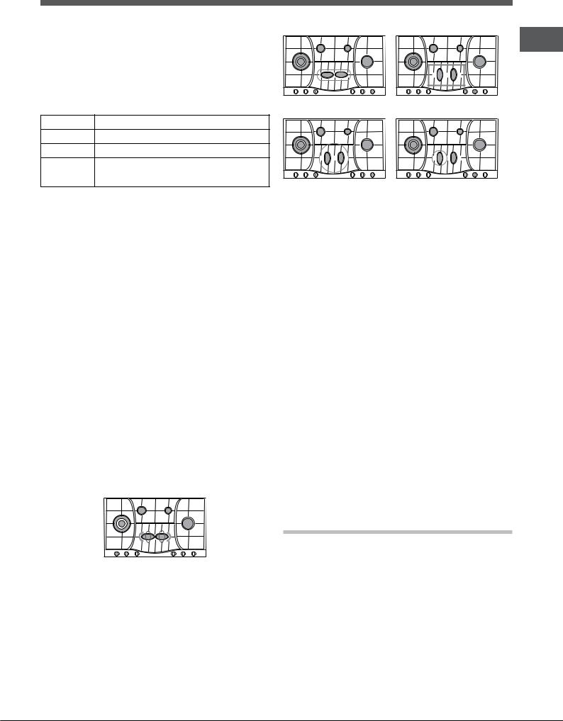
Description of the appliance
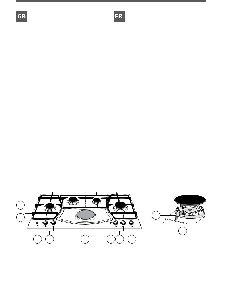
Overall view
1.Support Grid for Cookware
2.Gas burners
3.Control Knobs for electric hotplates*/COOKTOP BROILER*/
CERAMIC GLASS MODULE*
4.Control Knobs for gas burners
5.Indicator light for electric hotplates*/COOKTOP BROILER*/
CERAMIC GLASS MODULE*
6.electric hotplates*/COOKTOP BROILER*/CERAMIC GLASS MODULE*
7.Ignition button for Gas burners*
8.Ignition for Gas burners*
9.Safety devices*
•TheindicatorlightforELECTRIC HOTPLATES*/COOKTOP BROILER*/ CERAMIC GLASS MODULE * switches on whenever the selector knob is moved from the ‘off’ position.
•Control Knobs for gas burners and ELECTRIC HOTPLATES*/ COOKTOP BROILER*/CERAMIC GLASS MODULE * adjust the power or the size of the flame.
•Gasburnersdiffer in size and power. Use the diameter of the cookware to choose the most appropriate burner to cook with.
•Gasburnerignition* enablesaspecificburnertobelitautomatically.
•Safety device* stops the gas flow if the flame is accidentally extinguished.
* Only available on certain models.
Description de l’appareil
Vue d’ensemble
1.Grilles support de casseroles
2.Brûleurs à gaz
3.Manette de commande de laplaqueélectrique*/PLAQUE-GRILL*/
TABLE DE CUISSON VITROCÉRAMIQUE*
4.Manettes de commande des brûleurs gaz
5.Voyantfonctionnementdesplaque électrique*/PLAQUE-GRILL*/
TABLE DE CUISSON VITROCÉRAMIQUE*
6.plaque électrique*/PLAQUE-GRILL*/TABLE DE CUISSON VITROCÉRAMIQUE*
7.Bouton d’allumage des brûleurs gaz*
8.Bougie d’allumage des brûleurs gaz*
9.Dispositif de sécurité*
•Voyant fonctionnement des Table de cuisson Vitrocéramique*/PLAQUE GRILL*/plaque électrique* il s’allume dès que la manette n’est plus sur la position éteint.
•ManettesdecommandedesbrûleursgazetdelaVitrocéramique */PLAQUEGRILL*/plaqueélectrique*pourleréglagedelaflamme ou de la puissance.
•Brûleurs gaz ils ont plusieurs dimensions et puissances. Choisissez celui qui correspond le mieux au diamètre de votre casserole.
•La bougie d’allumage des brûleurs gaz* permet l’allumage automatique du brûleur sélectionné.
•Dispositifdesécurité* encasd’extinctionaccidentelledelaflamme, coupez immédiatement l’arrivée du gaz.
* N’existe que sur certains modèles.
2
1 |
|
|
|
|
9 |
|
|
|
|
|
|
|
|
|
|
6 |
1 |
|
|
|
|
5 |
2 |
|
|
|
|
|
|
|
|
|
|
4 |
3 |
|
|
|
|
|
8 |
7 |
4 |
6 |
5 |
4 |
3 |
7
Descripción del aparato
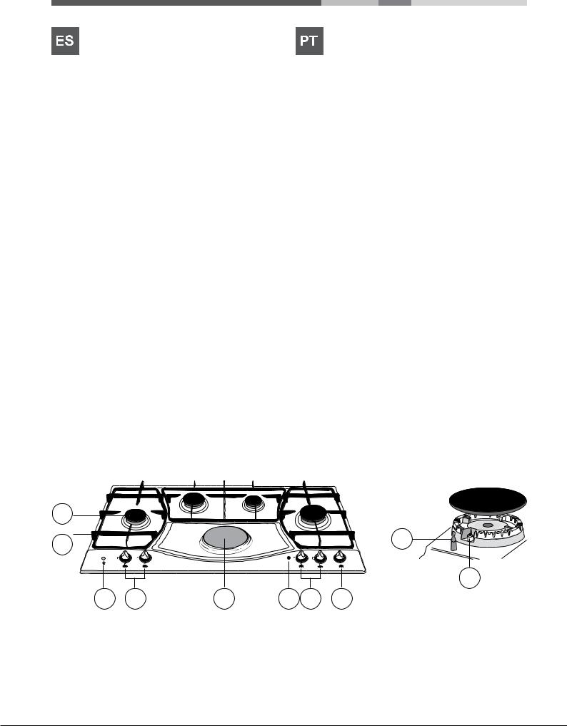
Vista en conjunto
1.Parrillas de apoyo para recipientes de cocción
2.Quemadores a gas
3.Mandos de la placa eléctrica*/PLACA VITROCERÁMICA*/
ASADERA*
4.Mandos de los quemadores a gas
5.Piloto de funcionamiento de la placa eléctrica*/PLACA
VITROCERÁMICA*ASADERA*/
6.placa eléctrica*/PLACA VITROCERÁMICA*/ASADERA*
7.Pulsador de encendido de los quemadores a gas*
8.Bujía de encendido de los quemadores a gas*
9.Dispositivo de seguridad*
•Piloto de funcionamiento de la PLACA ELÉCTRICA*/placa VitrocerámicA*/ASADERA*: se enciende cuando el mando está en cualquier otra posición que no sea la de apagado.
•Quemadores a gas: sondedistintasdimensionesypotencias.Elija siempreelmásadecuadoparaeldiámetrodelrecipientequevaautilizar.
•Mandos de los quemadores a gas y de la PLACA ELÉCTRICA*/ placa VitrocerámicA*/ASADERA* para la regulación de la llama o de la potencia.
•Bujíadeencendidodelosquemadoresagas*: permite el encendido automático del quemador.
•Dispositivo de seguridad*: si se apaga accidentalmente la llama, interrumpe la salida de gas.
* Presente sólo en algunos modelos.
Descrição do aparelho
Vista de conjunto
1.Grades de suporte para recipientes de cozedura
2.Queimadores a gás
3.Selectores de comando da chapaeléctrica*/CHAPAPARABIFE*/
Chapas para cozer de VIDRO CERÂMICA*
4.Selectores de comando dos queimadores a gás
5.Indicador luminoso chapaeléctrica*/CHAPAPARABIFE*/Chapas para cozer de VIDRO CERÂMICA*
6.chapa eléctrica*/CHAPA PARA BIFE*/Chapas para cozer de VIDRO CERÂMICA*
7.Dispositivo para acender os queimadores a gás*
8.Vela para acender os queimadores agás*
9.Dispositivo de segurança*
•Indicador luminoso funcionamento chapa para cozer de
Vidro Cerâmica*/chapa eléctricA*/CHAPA PARA BIFE* acende-se se o selector estiver em qualquer posição diferente daquela de desligado.
•Osqueimadores sãodediferentestamanhosepotências.Escolhao mais adequado ao diâmetro do recipiente a ser utilizado.
•Selectoresdecomandodosqueimadoresagás e da chapapara cozer de Vidro Cerâmica*/chapa eléctricA*/CHAPA PARA BIFE* para a regulação da chama ou da potência.
•Velaparaacenderosqueimadores a gás*: permite o acendimento automático do queimador escolhido.
•Dispositivo de segurança*: no caso em que a chama se apague acidentalmente, interrompe a saída do gás.
* Há somente em alguns modelos.
2
1 |
|
|
|
|
9 |
|
|
|
|
|
|
|
|
|
|
6 |
1 |
|
|
|
|
5 |
2 |
|
|
|
|
|
|
|
|
|
|
4 |
3 |
|
|
|
|
|
8 |
7 |
4 |
6 |
5 |
4 |
3 |
8

|
زاهجلافصو |
|||
|
ةماعةرظن |
|||
|
|
|||
1. |
|
يهطلايناوأةكبشمعدي1 .1 |
||
2. |
|
|||
3. |
*/ */ * |
زاغلاقراحم2 .2 |
||
4. |
|
*يجاجزلاكيماريسلاةدحو/*يهطلاحطسةاوشم/*يئابرهكلانيخستلاحاولأيفمكحتلاحيتافم3 .3 |
||
5. |
*/ */ */ * |
|||
زاغلاقراحميفمكحتلاحيتافم4 .4 |
||||
6. |
*/ */ * |
|||
*يجاجزلاكيماريسلاةدحو/*يهطلاحطسةاوشم/*يئابرهكلانيخستلاحاولأءوضرشؤم5 .5 |
||||
7. |
|
|||
|
* |
|
|
|
8. |
* |
*يجاجزلاكيماريسلاةدحو/*يهطلاحطسةاوشم/*يئابرهكلانيخستلاحاولأ6 .6 |
||
9. |
* |
*زاغلاقراحملاعشإرز7 .7 |
||
• |
“ ” */ */ |
*زاغلاقراحملاعشإ8 .8 |
||
*ناملأاةزهجأ9 .9 |
||||
|
|
|||
|
* |
|
|
|
• |
*/ */ * |
|
|
|
|
|
كيرحتدنعئضي*يجاجزلا كيماريسلا ةدحو / يهطلا حطس ةاوشم/يئابرهكلا نيخستلا حاولأ رشؤم |
• |
|
• |
|
|||
|
|
.ليغشتلافاقيإعضونمرايتخلااحاتفم |
|
|
|
كيماريسلاةدحو/يهطلاةاوشم/يئابرهكلانيخستلاحاولأوزاغلاقراحميفمكحتلاحيتافم |
• |
||
• |
* |
|||
• |
* |
.بهللامجحوأةقاطلاطبضت*يجاجزلا |
|
|
* |
|
يهطللقرحملضفأرايتخلايهطلاءانإرطقمدختسا.ةوقلاومجحلاةيحاننمزاغلا قراحمفلتخت |
• |
|
|
.هيلع |
|
||
|
|
.ايكيتاموتوأنيعمقرحملاعشإحيتي*زاغلاقرحم |
• |
|
|
|
.ةأجفبهللاأفطنالاحيفزاغلاقفدتفقوي**ناملأازاهج |
• |
|
.طقفةنيعمتازارطيفرفوتم*
2
1 |
|
|
|
|
9 |
|
|
|
|
|
|
|
|
|
|
6 |
1 |
|
|
|
|
5 |
2 |
|
|
|
|
|
|
|
|
|
|
4 |
3 |
|
|
|
|
|
8 |
7 |
4 |
6 |
5 |
4 |
3 |
9
GB Installation
!Before operating your new appliance please read this instruction booklet carefully. It contains important information for safe use, installation and care of the appliance.
!Please keep these operating instructions for future reference. Pass them on to possible new owners of the appliance.
Positioning
!Keep packaging material out of the reach of children. It can become a choking or suffocation hazard (see Precautions and tips).
!Theappliancemustbeinstalledbyaqualifiedprofessionalaccordingtothe instructions provided. Incorrect installation may cause harm to people and animals or may damage property.
!This unit may be installed and used only in permanently ventilated rooms in accordance with current national regulations). The following requirements must be observed:
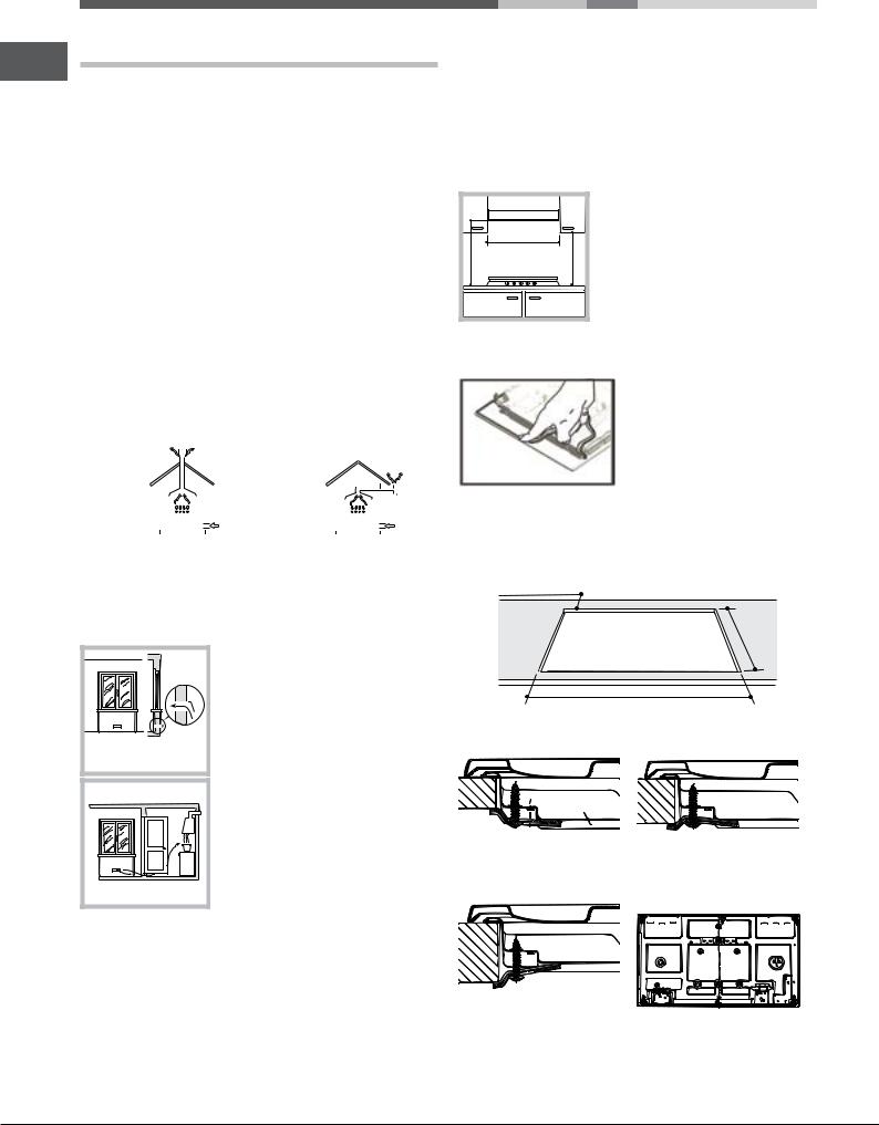
• The room must be equipped with an air extraction system that expels any combustion fumes. This may consist of a hood or an electric fan that automatically starts each time the appliance is switched on.
|
|
|
|
|
|
|
|
|
|
|
|
|
|
|
|
|
|
|
|
|
|
|
|
|
|
|
|
|
|
|
|
|
|
|
|
|
|
|
|
|
|
|
|
|
|
|
|
|
|
|
|
|
|
|
|
|
|
|
|
|
|
|
|
|
|
|
|
|
|
|
|
|
|
|
|
|
|
|
|
|
|
|
|
|
|
|
|
|
|
|
|
|
|
|
|
|
|
|
|
|
|
|
|
|
|
|
|
|
|
|
|
|
|
|
|
|
|
|
|
|
|
|
|
|
|
|
|
|
|
|
|
In a chimney stack or branched flue. |
Directly to |
|
|
|
|
|
|||||||||||||||
(exclusively for cooking appliances) |
the Outside |
|
|
|
|
|
|||||||||||||||
|
|
|
|
|
|
|
|
|
|
|
|
|
|
|
|
|
|
|
|
|
|
•The room must also allow proper air circulation, as air is needed for combustiontooccurnormally.Theflowofairmustnotbelessthan2m3/h per kW of installed power.
A |
Examples of ventilation holes for comburant air.
Adjacent |
Room to be |
Room |
Vented |
Enlarging the ventilation slot |
|
between window and floor. |
|
The air circulation system may take air directly from the outside by means of a pipe with an inner cross section of at least 100 cm2; the opening must not be vulnerable to any type of blockages.
The system can also provide the air needed for combustion indirectly, i.e. from adjacent rooms fitted with air circulation tubes as described above. However, these rooms must not be communal rooms, bedrooms or rooms that may present a fire hazard.
•Liquidpetroleumgassinkstothefloorasitisheavierthanair.Therefore, rooms containing LPG cylinders must also be equipped with vents to allow gas to escape in the event of a leak. As a result LPG cylinders, whether partially or completely full, must not be installed or stored in rooms or storage areas that are below ground level (cellars, etc.). It is advisable to keep only the cylinder being used in the room, positioned so that it is not subject to heat produced by external sources(ovens, fireplaces, stoves, etc. ) which could raise the temperature of the cylinder above 50°C.
Fitting the appliance
The following precautions must be taken when installing the hob:
•Kitchen cabinets adjacent to the appliance and taller than the top of the hob must be at least 600 mm from the edge of the hob.
•Hoods must be installed according to their relative installation instruction manualsandataminimumdistanceof650mmfromthehob(seefigure).
•Place the wall cabinets adjacent to the hood at a minimum height of 420 mm from the hob (see figure).
|
600mm min. |
650mmmin. |
420mmmin. |
If the hob is installed beneath a wall cabinet, the latter must be situated at a minimum of 700 mm above the hob.
Before the installation remove the grids and burners from the hob and turn it upside down, making sure you don’t damage the thermocouples and spark plugs.
Apply the seals that come with the appliance along the outer edges of the hob to prevent any passage of air, humidity and water (see Figure).
For proper application make sure the surfaces to be sealed are clean, dry and free of any grease/oil.
•Theinstallationcavityshouldhavethedimensionsindicatedinthefigure.
Fastening hooks are provided, allowing you to fasten the hob to tops that are between 20 and 40 mm thick. To ensure the hob is securely fastened to the top, we recommend you use all the hooks provided.
min. 55 mm.
475
mm .
835 mm.
Hook fastening diagram
Hooking position for top H=20mm Hooking position for top H=30mm
Front
Hooking position for top H=40mm Back
! Use the hooks contained in the “accessory pack”.
10
•Where the hob is not installed over a built-in oven, a wooden panel must be installed as insulation. This must be placed at a minimum distance of 20 mm from the lower part of the hob.
Ventilation
To ensure adequate ventilation, the back panel of the cabinet must be removed. It is advisable to install the oven so that it rests on two strips of wood, or on a completely flat surface with an opening of at least 45 x 560 mm (see diagrams).
. |
45 |
mm. |
mm |
|
|
560 |
|
|
Where a hob is installed above an oven without a forced ventilation cooling system, adequate ventilation must be provided inside the cabinet by means of air holes through which air can pass (see figure).
Electrical connection
Hobs equipped with a three-pole power supply cable are designed to operate with alternating current at the voltage and frequency indicated on the data plate (this is located on the lower part of the appliance). The earth wire in the cable has a green and yellow cover. If the appliance is to be installed above a built-in electric oven, the electrical connection of the hob and the oven must be carried out separately, both for electrical safety purposes and to make extracting the oven easier.
Connecting the supply cable to the mains
Install a standardised plug corresponding to the load indicated on the data plate.
The appliance must be directly connected to the mains using an omnipolar circuit-breaker with a minimum contact opening of 3 mm installed between the appliance and the mains. The circuit-breaker must be suitable for the charge indicated and must comply with current electrical regulations (the earthing wire must not be interrupted by the circuit-breaker). The supply cable must not come into contact with surfaces with temperatures higher than 50°C.
! The installer must ensure that the correct electrical connection has been made and that it is compliant with safety regulations.
Before connecting to the power supply, make sure that:
•The appliance is earthed and the plug is compliant with the law.
•Thesocketcanwithstandthemaximumpoweroftheappliance,whichis indicated on the data plate.
•Thevoltageisintherangebetweenthevaluesindicatedonthedataplate.
•The socket is compatible with the plug of the appliance. If the socket is incompatible with the plug, ask an authorised technician to replace it. Do not use extension cords or multiple sockets.
! Once the appliance has been installed, the power supply cable and the |
GB |
electrical socket must be easily accessible. |
!The cable must not be bent or compressed.
!The cable must be checked regularly and replaced by authorised technicians only (see Assistance).
!The manufacturer declines any liability should these safety measures not be observed.
Gas connection
The appliance should be connected to the main gas supply or to a gas cylinder in compliance with current national regulations. Before carrying out the connection, make sure the cooker is compatible with the gas supply you wish to use. If this is not the case, follow the instructions indicated in the paragraph “Adapting to different types of gas.”
When using liquid gas from a cylinder, install a pressure regulator which complies with current national regulations.
!Checkthatthepressureofthegassupplyisconsistentwiththevaluesindicated inTable1(“Burnerandnozzlespecifications”).Thiswillensurethesafeoperation andlongevityofyourappliancewhilemaintainingefficientenergyconsumption.
Connection with a rigid pipe (copper or steel)
! Connection to the gas system must be carried out in such a way as not to place any strain of any kind on the appliance.
There is an adjustable L-shaped pipe fitting on the appliance supply ramp and this is fitted with a seal in order to prevent leaks. The seal must always be replaced after rotating the pipe fitting(seal provided with appliance).The gas supply pipe fitting is a threaded 1/2 gas cylindrical male attachment.
Connecting a flexible jointless stainless steel pipe to a threaded attachment
Thegassupplypipefittingisathreaded1/2gascylindricalmaleattachment.
These pipes must be installed so that they are never longer than 2000 mm when fully extended. Once connection has been carried out, make sure that theflexiblemetalpipedoesnottouchanymovingpartsandisnotcompressed.
! Only use pipes and seals that comply with current national regulations.
Checking the tightness of the connection
! When the installation process is complete, check the pipe fittings for leaks using a soapy solution. Never use a flame.
Adapting to different types of gas
To adapt the hob to a different type of gas other than default type (indicated on the rating plate at the base of the hob or on the packaging), the burner nozzles should be replaced as follows:
1.Remove the hob grids and slide the burners off their seats.
2.Unscrew the nozzles using a 7 mm socket spanner, and replace them with nozzles for the new type of gas (see table 1 “Burner and nozzle characteristics”).
3.Reassemble the parts following the above procedure in the reverse order.
4.Once this procedure is finished, replace the old rating sticker with one indicating the new type of gas used. Sticker are available from any of our Service Centres.
11
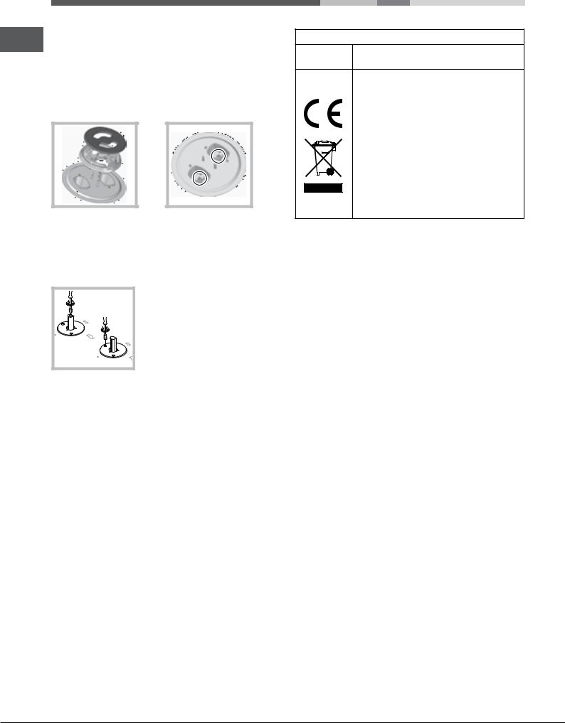
Replacing the Triple ring burner nozzles*
GB 1. Remove the pan supports and lift the burners out of their housing. The burner consists of two separate parts (see pictures).
2.Unscrew the nozzles using a 7 mm socket spanner. Replace the nozzles withmodelsthatareconfiguredforusewiththenewtypeofgas(seeTable
1). The two nozzles have the same hole diameter.
3.Replace all the components by completing the above operations in reverse order.
•Adjusting the burners’primary air
Does not require adjusting.
•Setting the burners to minimum
1. Turn the tap to the low flame position;
2. Removetheknobandadjusttheadjustment screw, which is positioned in or next to the tap pin, until the flame is small but steady.
3.Having adjusted the flame to the required low setting, while the burner is alight, quickly change the position of the knob from minimum to maximum and vice versa several times, checking that the flame does not go out.
4.Someapplianceshaveasafetydevice(thermocouple)fitted.Ifthedevice fails to work when the burners are set to the low flame setting, increase this low flame setting using the adjusting screw.
5.Once the adjustment has been made, replace the seals on the by-passes using sealing wax or a similar substance.
!If the appliance is connected to liquid gas, the regulation screw must be fastened as tightly as possible.
!Once this procedure is finished, replace the old rating sticker with one indicating the new type of gas used. Stickers are available from any of our Service Centres.
!Should the gas pressure used be different (or vary slightly) from the recommended pressure, a suitable pressure regulator must be fitted to the inlet pipe (in order to comply with current national regulations).
* Only available on certain models.
DATA PLATE
Electrical |
see data plate |
connections |
This appliance conforms to the following
European Economic Community directives:
-2006/95/EEC dated 12/12/06 (Low Voltage) and subsequent amendments
-2004/108/EEC dated 15/12/04 (Electromagnetic Compatibility) and
subsequent amendments
- 93/68/EEC dated 22/07/93 and subsequent amendments.
- 2009/142/EEC dated 30/11/09 (Gas) and subsequent amendments.
- 2012/19/EC and subsequent amendments.
12
|
|
|
|
|
|
|
|
|
|
|
|
|
|
|
Burner and nozzle specifications |
|
|
|
|
|
|
|
|
|
|
||||
|
|
|
|
|
|
|
|
|
GB |
|||||
Table 1 |
|
|
|
|
|
|
|
|
|
|
|
|
|
|
|
|
|
|
|
|
|
|
|
|
|
|
|
|
|
|
|
|
|
|
Liquid Gas |
|
Natural Gas |
|
|
|||||
|
|
|
|
|
|
|
|
|||||||
Burner |
Diameter |
Thermal Power |
By-pass |
Nozzle |
Flow* |
|
Nozzle |
|
Flow* |
|
||||
|
(mm) |
kW (p.c.s.*) |
1/100 |
1/100 |
g/h |
|
1/100 |
|
l/h |
|
||||
|
|
Nominal |
|
Reduced |
(mm) |
(mm) |
*** |
|
** |
(mm) |
|
|
|
|
|
|
|
|
|
|
|
||||||||
|
|
|
|
|
|
|
|
|
|
|
||||
Rapid (R) |
100 |
3.00 |
|
0.70 |
39 |
86 |
218 |
|
214 |
116 (Y) |
|
286 |
|
|
|
|
|
|
|
|
|
|
|
|
|
|
|
|
|
Reduced Rapid (RR) |
100 |
2.60 |
|
0.70 |
39 |
80 |
189 |
|
186 |
110 (Y) |
|
248 |
|
|
|
|
|
|
|
|
|
|
|
|
|
|
|
|
|
Semi Rapid (S) |
75 |
1.65 |
|
0.40 |
28 |
64 |
120 |
|
118 |
96 (Z) |
|
157 |
|
|
|
|
|
|
|
|
|
|
|
|
|
|
|
|
|
Auxiliary (A) |
55 |
1.00 |
|
0.40 |
28 |
50 |
73 |
|
71 |
71 (X) |
|
95 |
|
|
|
|
|
|
|
|
|
|
|
|
|
|
|
|
|
Triple Crown (TC) |
130 |
3.25 |
|
1.50 |
61 |
91 |
236 |
|
232 |
133 (Z) |
|
309 |
|
|
|
|
|
|
|
|
|
|
|
|
|
|
|
|
|
Semi-Fish burner (SP) |
- |
1.50 |
|
0.70 |
39 |
60 |
109 |
|
107 |
88 |
|
143 |
|
|
|
|
|
|
|
|
|
|
|
|
|
|
|
|
|
Supply |
|
Nominal (mbar) |
|
|
28-30 |
|
37 |
20 |
|
|
|
|||
pressures |
|
Minimum (mbar) |
|
|
20 |
|
25 |
17 |
|
|
|
|||
|
|
Maximum (mbar) |
|
|
35 |
|
45 |
25 |
|
|
|
|||
|
|
|
|
|
|
|
|
|
|
|
|
|
|
|
*A 15°C e 1013,25 mbar-dry gas
** |
Propane |
P.C.S. = 50.37 MJ/Kg |
*** |
Butane |
P.C.S. = 49.47 MJ/Kg |
|
Natural |
P.C.S. = 37.78 MJ/m3 |
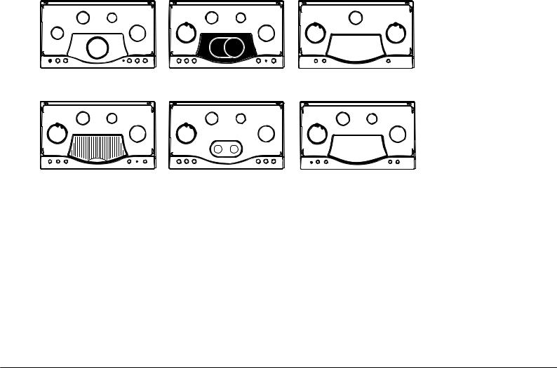
S |
A |
|
S |
A |
|
S |
S |
|
R |
TC |
RR |
TC |
TC |
PH 941 MS |
|
|
PH 941 MSTV |
|
|
PH 930 MST |
|
|
|
|
PH 941 MSTV GH |
|
PC 930 T X |
|
|
S |
A |
|
S |
A |
|
S |
A |
TC |
|
RR |
TC |
|
RR |
TC |
RR |
|
|
|
SP |
|
|
|
|
PH 941 MSTB |
|
|
PH 960 MST |
|
|
PH 940 MST |
|
PH 941 MSTB GH |
|
PH 960 MST GH |
|
|
|
||
13
GB Start-up and use
! The position of the corresponding gas burner or electric hotplate* is shown on every knob.
Gas burners
Each burner can be adjusted to one of the following settings using the corresponding control knob:
●Off
Maximum
Minimum
To light one of the burners, hold a lit match or lighter near the burner and, at the same time, press down and turn the corresponding knob anti-clockwise to the maximum setting.
Since the burner is fitted with a safety device, the knob should be pressed for approximately 2-3 seconds to allow the automatic device keeping the flame alight to heat up.
When using models with an ignition button, light the desired burner pressing down the corresponding knob as far as possible and turning it anticlockwise towards the maximum setting.
! If a flame is accidentally extinguished, turn off the control knob and wait for at least 1 minute before trying to relight it.
To switch off the burner, turn the knob in a clockwise direction until it stops
(when reaches the “●” position).
Practical advice on using the burners
To ensure the burners operate efficiently:
•Use appropriate cookware for each burner(see table) so that the flames do not extend beyond the bottom of the cookware.
•Always use cookware with a flat base and a cover.
•Whenthecontentsofthepanreachboilingpoint,turntheknobtominimum.
Burner |
Ø Cookware Diameter (cm) |
|
|
Rapid (R) |
24 - 26 |
|
|
Reduced Rapid (RR) |
24 - 26 |
|
|
Semi Rapid (S) |
16 - 20 |
|
|
Auxiliary (A) |
10 - 14 |
|
|
Semi-FishBurner (SP) |
16 - 20 |
|
|
Triple Crown (TC) |
24 - 26 |
|
|
To identify the type of burner, refer to the designs in the section entitled, “Burner and Nozzle Specifications”.
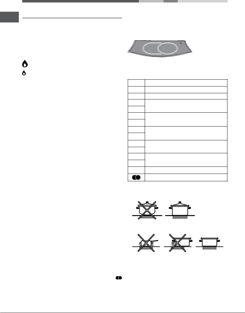
Ceramic Glass Module*
Thiscooktopisfittedwithdual-ringradiantheatingelementslocatedbeneath the glass. It is possible to turn on only the circular part of the elemement (identifiedbytheletter“A”) or the cooking surface can be enlarged by turning on both “A” and “B”. To turn only the circular “A” element, simply turn the knob in the clockwise direction to any one of the 12 available settings. To add the “B” section, turn the knob to setting 12 and then click it into the setting. Then proceed by turning the knob in the counter-clockwise direction to one of the 12 settings.
* Only available on certain models.
The figure shows the heating zones, which become red when the element is turned on.
A.Circular heating zone;
B.Extended heating zone;
C.Indicator light to show when the cooking zone is above 60°C, even after the heating element has been turned off.
B A
When the knob is on any of the settings other than “Off”, the Indicator Light for Ceramic Glass Module comes on.
Practical Advise on Using the Ceramic Glass Module*
Set. Radiant Burner
0Off.
1To melt butter and chocolate.
2
3
To heat liquids.
4
5
For creams and sauces.
6
7
For cooking at the boiling point.
8
9
For Roasts.
10
11
For boiling large pieces of meat.
12 For frying.
For utilising both cooking areas.
To obtain the best results from your hob:
•Use flat-bottomed pans to ensure that they adhere to the cooking zone perfectly.
•Alwaysusepanswithadiameterthatislargeenoughtocoverthehotplate fully, in order to use all the available heat.
•Make sure that the bottom of the cookware is always dry and clean to guarantee correct adherence and long life, not only for the cooking zones but also for the cookware itself.
•Avoid using the same cookware that is used on gas burners: the heat concentration on gas burners may deform the base of the pan, causing it not to adhere correctly.
•Never leave a cooking zone on without cookware on it because as it heats up and rapidly reaches the maximum level, which could damage the heating elements.
14
! There might be traces of grease left by the glue used to seal the glass which should be removed before using the appliance with a mild cleaning product. During the first few hours of use you might smell rubber but this will disappear quickly.
Electric hotplates*
The corresponding knob may be turned clockwise or anti-clockwise and set to six different positions:
Setting |
Normal or Fast Plate |
0Off
1Minimum power
2-5 |
Intermediate powers |
|
|
6 |
Maximum power |
When the selector knob is in any position other than the off position, the ‘on’ light comes on.
Practical advice on using the electric hotplates*
To avoid heat loss and damage to the hotplates, use pans with a flat base, whose diameter is no less than that of the hotplate itself.
Setting |
Normal or Fast Plate |
|
|
0 |
Off |
|
|
1 |
Cooking vegetables, fish |
|
|
2 |
Cooking patatoes (using steam) soups, |
|
chickpeas, beans. |
3 |
Continuing the cooking of large quantities of |
|
food, minestrone. |
4 |
For roasting (average) |
|
|
5 |
For roasting (above average) |
|
|
6 |
For browning and reaching a boil in a short time |
|
|
!Beforeusingthehotplatesforthefirsttime,youshouldheatthematmaximum temperature for approximately 4 minutes, without placing any pans on them. During this initial stage, their protective coating hardens and reaches its maximum resistance.
Practical Advice on Using the Half Fish-Kettle Burner*
The two “Half Fish-Kettle” burners, are eliptic in form and can be turned up to 90°.This makes the cooktop more flexible in terms of how it can be used.
GB
Fig. A |
Fig. B |
Fig. C |
Fig. D |
Practical Advise on Using the Broiler*
Preheat the broiler by turning the knob to 12. Settings 1-8 are recommended for reheating food or for keeping it warm after it has been cooked. In general, cooking vegetables can cause stains which are difficult to remove.
Food |
Weight |
Knob |
Preheating |
Cooking |
|
|
(Kg) |
Setting |
(min.) |
time |
|
|
|
|
|
(min.) |
|
|
|
|
|
|
|
Pork |
0,50 |
12 |
5 |
15 |
|
chops |
10 |
20 |
|||
|
|
||||
|
|
|
|||
Steak |
0,60 |
12 |
5 |
10 |
|
|
|
|
|
|
|
Sausages |
0,45 |
10 |
5 |
20 |
|
|
|
|
|
|
|
Shish Kabobs |
0,40 |
12 |
5 |
14 |
|
(Meat) |
|||||
|
|
|
|
||
|
|
|
|
|
|
Hamburger |
0,40 |
10 |
5 |
15 |
|
|
|
|
|
|
|
Toasted |
N° 3 |
11 |
5 |
2 |
|
Sandwiches |
|||||
|
|
|
|
||
|
|
|
|
|
|
Bread |
3 Slices |
11 |
5 |
3 |
|
|
|
|
|
|
|
Aubergines |
3 Slices |
12 |
5 |
5 - 7 |
|
|
|
|
|
|
|
Oven-roasted |
N° 4 |
12 |
5 |
10 - 15 |
|
Tomatoes |
|||||
|
|
|
|
||
|
|
|
|
|
To turn the two burners 90°, proceed as follows:
•Make sure that the burners are cool;
•Lift the burner completely out of its housing;
•Replace it in its housing in the position desired;
•Make sure that the burners are positioned correctly before use.
In addition, the two burners can be used in tandem or speartely with cookware of different shapes and sizes:
•Double burner for a fish-kettle or oval cookware (Fig.A).
•Doubleburnerforagriddleorrectangular/squarecookwarewithminimum dimensions of 28x28 cm (Fig. B)
•Double burner for large cookware (diameter of 26-28 cm) (Fig.C).
•Single burner for medium size cookware(diameter of 16-20 cm)(Fig.D).
Precautions and tips
! This appliance has been designed and manufactured in compliance with international safety standards. The following warnings are provided for safety reasons and must be read carefully.
General safety
•This is a class 3 built-in appliance.
•Gas appliances require regular air exchange to maintain efficient operation. When installing the hob, follow the instructions provided in the paragraph on “Positioning” the appliance.
•These instructions are only valid for the countries whose symbols appear in the manual and on the serial number plate.
•Theappliancewasdesignedfordomesticuseinsidethehomeandisnot intended for commercial or industrial use.
*Only available on certain models.
15
|
• Theappliancemustnotbeinstalledoutdoors,evenincoveredareas.Itis |
|
GB |
||
extremely dangerous to leave the appliance exposed to rain and storms. |
||
|
• Donottouchtheappliancewithbarefeetorwithwetordamphandsand |
|
|
||
|
feet. |
|
|
• Theappliancemustbeusedbyadultsonlyforthepreparationoffood, |
|
|
inaccordancewiththeinstructionsoutlinedinthisbooklet.Anyother |
|
|
use of the appliance (e.g. for heating the room) constitutes improper |
|
|
use and is dangerous. The manufacturer may not be held liable for |
|
|
any damage resulting from improper, incorrect and unreasonable |
|
|
use of the appliance. |
|
|
• Ensurethatthepowersupplycablesofotherelectricalappliancesdonot |
|
|
come into contact with the hot parts of the oven. |
|
|
• The openings used for ventilation and dispersion of heat must never be |
|
|
covered. |
|
|
• Alwaysmakesuretheknobsareinthe“●”/“○” position when the appliance |
|
|
is not in use. |
|
|
• Whenunpluggingtheappliancealwayspulltheplugfromthemainssocket, |
|
|
do not pull on the cable. |
|
|
• Nevercarryoutanycleaningormaintenanceworkwithouthavingdetached |
|
|
the plug from the mains. |
|
|
• Incaseofmalfunction,undernocircumstancesshouldyouattempttorepair |
|
|
the appliance yourself. Repairs carried out by inexperienced persons may |
|
|
cause injury or further malfunctioning of the appliance. Contact a Service |
|
|
Centre (see Assistance). |
|
|
• Always make sure that pan handles are turned towards the centre of the |
|
|
hob in order to avoid accidental burns. |
|
|
• Donotclosetheglasscover(ifpresent)whenthegasburnersorelectric |
|
|
hotplates are still hot. |
|
|
• Do not leave the electric hotplate switched on without a pan placed on it. |
|
|
• Do not use unstable or deformed pans. |
|
|
• The appliance should not be operated by people (including children) |
|
|
with reduced physical, sensory or mental capacities, by inexperienced |
|
|
individuals or by anyone who is not familiar with the product. These |
|
|
individuals should, at the very least, be supervised by someone who |
|
|
assumes responsibility for their safety or receive preliminary instructions |
|
|
relating to the operation of the appliance. |
|
|
• Do not let children play with the appliance. |
|
|
• Theapplianceisnotintendedtobeoperatedbymeansofanexternal |
|
|
timer or separate remote-control system. |
Disposal
•When disposing of packaging material: observe local legislation so that the packaging may be reused.
•The European Directive 2012/19/EC on Waste Electrical and Electronic Equipment (WEEE), requires that old household electrical appliances must not be disposed of in the normal unsorted municipal waste stream. Old appliances must be collected separately in order to optimise the recovery and recycling of the materials they contain and reduce the impact on human health and the environment. The crossed out “wheeled bin” symbol on the product reminds you of your obligation, that when you dispose of the appliance it must be separately collected.
Consumers should contact their local authority or retailer for information concerning the correct disposal of their old appliance.
Maintenance and care
Switching the appliance off
Disconnect your appliance from the electricity supply before carrying out any work on it.
Cleaning the appliance
!Do not use abrasive or corrosive detergents such as stain removers, anti-rust products, powder detergents or sponges with abrasive surfaces: these may scratch the surface beyond repair.
!Never use steam cleaners or pressure cleaners on the appliance.
•It is usually enough to wash the hob with a damp sponge and dry it with absorbent kitchen roll.
•The removable parts of the burners should be washed frequently with warm water and soap and any burnt-on substances removed.
•Forhobswhichligthautomatically,theterminalpartoftheelectronicinstant lighting devices should be cleaned frequently and the gas outlet holes should be checked for blockages.
•Theelectrichotplatesshouldbecleanedwithadampclothandlubricated with a little oil while still warm.
•Before using the ceramic glass module, the surface must be cleaned, using a damp cloth to remove dust or food residues. The ceramic glass surface should be cleaned regularly with a soultion of warm water and a non-abrasive detergent.
•Stainless steel can be marked by hard water that has been left on the surface for a long time, or by aggressive detergents containing phosphorus. After cleaning, rinse and dry any remaining drops of water.
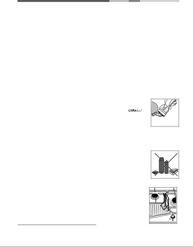
Periodically, special products will need to be used to clean the surface. First, remove all food buildup or grease with a
cleaning scraper, e.g |
(not |
supplied). |
|
Clean the cooking surface when it is still warm with a suitable cleaning product (such as the one in the Solutions product line available from anyAfter-Sales Service
Centre) and paper towels. Then rub with a damp cloth and dry.Aluminum foil, plastic items, objects made of synthetic material, sugar or foods with a high sugar content that have melted onto the surface must be removed immediatley with a scraper while the cooking surface is still hot.
Specialcleaningproductsforceramicglass surfaces form a transparent protective layer which fights diry buildup. This also protects the surface from damage caused by food with a high sugar content. Do not use abrasive sponges or cleaning products under any circumstances. This holds true for chemically aggressive cleaners, like oven sprays and stain removers.
• When cleaning the grill, it is recommeded that you do so while it is still hot, using the handles provided to move it from the cooktop to the sink. To remove the pan beneath the grill, it is a good idea to wait until the heating element has cooled (roughly after 15 minutes).
16
|
|
|
|
|
|
|
|
|
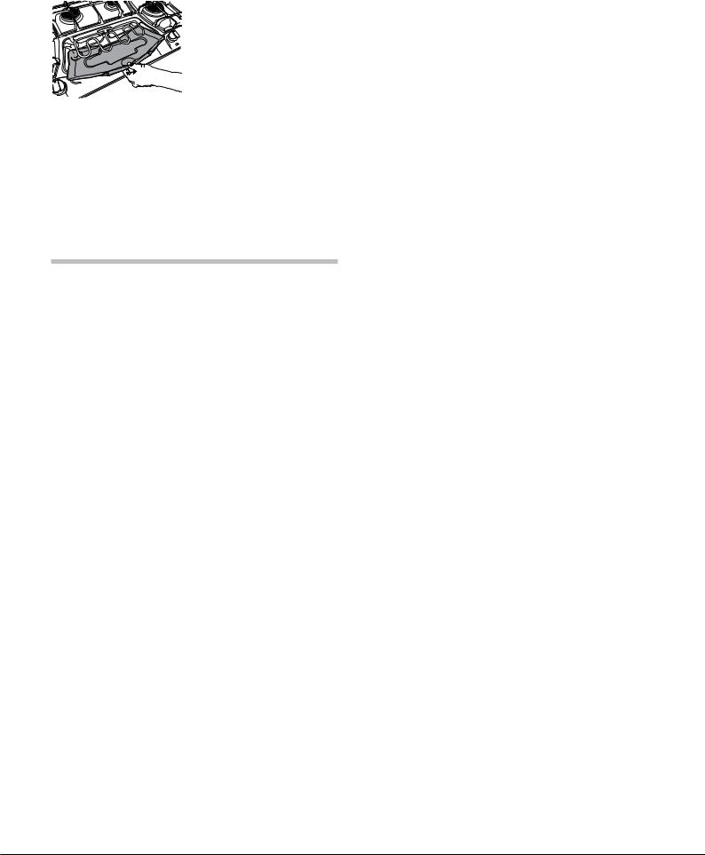
The packaging includes the cast-iron |
GB |
|
|
|||
|
steak grill and the stainless-steel |
|
|
|
|||
|
grease-collection tray together with |
|
|
|
grids and burners. |
|
|
|
Place the tray under the heating |
|
|
|
element (see Figure) and the streak |
|
|
|
grill over it so as to enclose the heating |
|
|
|
element in between. |
|
|
|
|
||
Gas tap maintenance
Over time, the taps may become jammed or difficult to turn. If this happens, the tap must be replaced.
!Thisproceduremustbeperformedbyaqualifiedtechnicianauthorised by the manufacturer.
Troubleshooting
It may happen that the appliance does not function properly or at all. Before calling the service centre for assistance, check if anything can be done. First, check to see that there are no interruptions in the gas and electrical supplies, and, in particular, that the gas valves for the mains are open.
The burner does not light or the flame is not even around the burner.
Check whether:
• The gas holes on the burner are clogged.
• All the movable parts that make up the burner are mounted correctly.
• There are draughts near the appliance.
The flame dies in models with a safety device.
Check to make sure that:
• You pressed the knob all the way in.
• You keep the knob pressed in long enough to activate the safety device.
• The gas holes are not blocked in the area corresponding to the safety device.
The burner does not remain lit when set to minimum.
Check to make sure that:
• The gas holes are not blocked.
• There are no draughts near the appliance.
• The minimum setting has been adjusted properly.
The cookware is unstable.
Check to make sure that:
• The bottom of the cookware is perfectly flat.
• The cookware is positioned correctly at the centre of the burner.
• The pan support grids have been positioned correctly.
17

FR Installation
! Conservez ce mode d’emploi pour pouvoir le consulter à tout moment.
BE En cas de vente, de cession ou de déménagement, veillez à ce qu’il suive l’appareil pour informer le nouveau propriétaire sur son fonctionnement et lui
fournir les conseils correspondants.
LU
! Lisez attentivement les instructions : elles contiennent des conseils NL importants sur l’installation, l’utilisation et la sécurité de votre appareil
Les appareils réglés en usine pour (voir la plaquette d’immatriculation et la plaquette prédisposition gaz de l’appareil):
•gaz Naturel Catégorie II2E+3+ pour la France et la Belgique;
•gaz Naturel Catégorie I2E pour le Luxembourg;
•gaz Naturel Catégorie I2Lpour la Hollande.
Un ultérieur réglage n’est donc pas nécessaire.
Conditions réglementaires d’installation (Pour la France)
Le raccordement gaz devra être fait par un technicien qui assurera la bonne alimentation en gaz et le meilleur réglage de la combustion des brûleurs. Ces opérations d’installation, quoique simples, sont délicates et primordiales pour que votre table de cuisson vous rende le meilleur service. L’installation doit être effectuée conformément aux textes réglementaires et règles de l’art en vigueur, notamment:
•Arrêté du 2 août 1977. Règles techniques et de sécurité applicables aux installations de gaz combustibles et d’hydro-carbures liquéfiés situées à l’intérieur des bâtiments d’habitation et de leurs dépendances.
•Norme DTU P45-204. Installations de gaz (anciennement DTU n° 61-1-installations de gaz -Avril 1982 + additif n°1 Juillet 1984).
•Règlement sanitaire départemental.
Positionnement
!Les emballages ne sont pas des jouets pour enfants, il faut les mettre au rebut en respectant la réglementation sur le tri sélectif des déchets (voir Précautions et conseils).
!L’installation doit être effectuée par un professionnel du secteur conformément aux instructions du fabricant. Une mauvaise installation peut causer des dommages à des personnes, des animaux ou des biens.
!Cet appareil peut être installé et fonctionner seulement dans des locaux qui sont aérés en permanence, selon les prescriptions des Normes:
• Pour la France selon les Normes Nationales en vigueur.
• Pour la Belgique NBN D51-003 et NBN D51-001 en vigueur.
• Pour le Luxembourg selon les Normes Nationales en vigueur.
• Pour la Hollande NEN-1078 en vigueur.
Il faut observer les conditions suivantes:
•Lapiècedoitprévoirunsystèmed’évacuationversl’extérieurdesfumées de combustion, réalisé au moyen d’une hotte ou par ventilateur électrique qui entre automatiquement en fonction dès que l’on allume l’appareil.
En cas de cheminée ou conduit de fumée ramifié |
Directement |
(réservé aux appareils de cuisson) |
à l'externe |
•La pièce doit prévoir un système qui consent un apport d’air nécessaire à une régulière combustion. Le flux d’air nécessaire à la combustion ne doit pas être inférieur à 2 m3/h par kW de puissance installée.
A |
Exemples d'ouverture de ventilation
pour l'air comburant
Local |
Local à |
adjacent |
ventiler |
Agrandissement de la fissure |
|
entre la porte et le sol |
|
Le système peut être réalisé en prélevant l’air directement de l’extérieur du bâtiment au moyen d’un conduit d’au moins100 cm2 de section utile qui ne risque pas d’être bouché accidentellement.
Ou, de manière indirecte depuis des locaux adjacents et équipés d’un conduit de ventilation avec l’extérieur comme susmentionné; ces locaux ne doivent pas être des parties communes du bâtiment, des chambres à coucher ou des locaux à risque d’incendie.
•(Pour la France et la Belgique) Les gaz de pétrole liquéfiés, plus lourds que l’air, se déposent et stagnent vers le bas. Les locaux qui contiennent donc des bouteilles de G.P.L doivent prévoir des ouvertures vers l’extérieur afin de permettre l’évacuation du gaz par le bas en cas de fuites accidentelles. Les bouteilles de GPL, qu’elles soient vides ou partiellement pleines, ne devront donc pas être installées ou entreposées dans des locaux qui se trouvent au dessous du niveau du sol (caves etc.). Il est opportun de n’entreposer dans le local que la bouteille que vous êtes en train d’utiliser, placée de façon à ne pas être sujette à l’action directe de sources de chaleur (fours, feux de bois, poêles etc.) qui peuvent atteindre des températures dépassant 50°C.
Encastrement
Pour une installation correcte de la table de cuisson, il faut se conformer aux instructions suivantes :
•Les meubles jouxtant la table, dont la hauteur dépasse celle du plan de cuisson, doivent être placés à au moins 600 mm du bord du plan.
•Leshottesdoiventêtreinstalléesconformémentauxinstructionsreportées dans leur notice d’installation et à au moins 650 mm de distance.
•Les éléments hauts jouxtant la hotte doivent être placés à au moins 420 mm de distance du plan de travail (voir figure).
|
600mm min. |
650mmmin. |
420mmmin. |
En cas d’installation de la table de cuisson sous un élément haut, ce dernier devra être monté à au moins 700 mm de distance du plan (voir figure).
Avant de procéder à l’installation, enlever les grilles et les brûleurs du plan de cuisson et renverser celui-ci en veillant à ce que les thermocouples et les bougies ne soient pas endommagés.
Appliquer les joints fournis avec l’appareil sur les bords extérieurs du plan de cuisson pour empêcher le passage de l’air, de l’humidité et de l’eau
(voir figure).
Pour une application correcte, s’assurer que les surfaces à sceller sont propres,
sèches et sans traces de graisses/huiles.
•La découpe du meuble doit avoir les dimensions indiquées par la figure. Des crochets de fixation sont prévus pour fixer la table sur des plans de 20à40mmd’épaisseur.Pourbienfixerlatable,utiliseztouslescrochets fournis.
18
Loading...