


 Loading...
T775A/B/M Series 2000 Electronic
Stand-Alone Controllers
INSTALLATION INSTRUCTIONS
|
|
|
|
PRODUCT DESCRIPTION |
|
||||
|
|
|
|
The T775 electronic stand-alone controllers are the next |
|||||
|
|
|
|
generation of commercial and agricultural controls |
|||||
|
|
|
|
capable of remote sensing of temperature and providing |
|||||
|
|
|
|
switched and/or proportional outputs to various types of |
|||||
|
|
|
|
loads. |
|
|
|
|
|
|
|
|
|
Five models have analog (modulating) outputs for |
|||||
|
|
|
|
actuator and motor control, and NEMA-4 weatherproof |
|||||
|
|
|
|
enclosures are available for wet environments. |
|||||
|
|
|
|
IMPORTANT |
|
|
|
|
|
|
|
|
|
|
Each T775A/B/M controller is an operating |
||||
|
|
|
|
|
control, not a limit or safety control. If used in |
||||
|
|
|
|
|
applications requiring safety or limit controls, a |
||||
|
|
|
|
|
separate safety or limit control device is |
||||
|
|
|
|
|
required. |
|
|
|
|
|
|
Table 1. T775A/B/M Controller Configurations. |
|
|
|
||||
|
|
|
|
|
|
|
|
|
|
Controller |
|
|
|
SPDT |
Analog |
Floating |
|
Nbr of |
|
|
|
|
Relay |
(Mod) |
Sensor |
Sensors |
|
||
a |
Description |
Replaces |
Outputs |
b |
c |
Inputs |
Included |
Enclosure |
|
Model |
Outputs |
Outputs |
|||||||
T775A2009 |
Standard |
T775A1001 |
|
1 |
None |
None |
1 |
1 |
NEMA 1 |
T775B2016 |
Standard |
N/A |
|
2 |
None |
1 |
2 |
1 |
NEMA 4X |
|
|
|
|
|
|
|
|
|
|
T775B2024 |
Standard |
T775C1009 |
T775D1008 |
4 |
None |
2 |
2 |
1 |
NEMA 4X |
|
|
|
|
|
|
|
|
|
|
T775B2032 |
Standard |
T775A1019 |
T775B1000 |
2 |
None |
1 |
2 |
1 |
NEMA 1 |
|
|
|
|
|
|
|
|
|
|
T775B2040 |
Standard |
T775A1027 |
T775A1035 |
4 |
None |
2 |
2 |
1 |
NEMA 1 |
|
|
T775B1018 |
T775B1026 |
|
|
|
|
|
|
|
|
T775B1042 |
|
|
|
|
|
|
|
T775M2006 |
Modulating |
N/A |
|
None |
2 |
N/A |
2 |
1 |
NEMA 1 |
|
|
|
|
|
|
|
|
|
|
T775M2014 |
Modulating |
T775G1005 |
T775G1013 |
4 |
2 |
N/A |
2d |
1 |
NEMA 4X |
|
|
T775G1021 |
T775G1039 |
|
|
|
|
|
|
T775M2022 |
Modulating |
N/A |
|
2 |
2 |
N/A |
2d |
1 |
NEMA 4X |
T775M2030 |
Modulating |
T775E1114 |
T775F1022 |
4 |
2 |
N/A |
2d |
1 |
NEMA 1 |
|
|
T775F1055 |
T775F1089 |
|
|
|
|
|
|
T775M2048 |
Modulating |
T775E1015 |
T775E1023 |
2 |
2 |
N/A |
2d |
1 |
NEMA 1 |
|
|
T775E1056 |
T775E1064 |
|
|
|
|
|
|
|
|
T775E1098 |
|
|
|
|
|
|
|
aAll models include a digital input for use with the disable or setback option.
bThe modulating (analog) outputs are 4-20 mA, 0-10 Vdc, 2-10 Vdc, or Series 90 selectable.
cEach floating output eliminates two SPDT relays.
dThese models can support a high/low modulating limit at Sensor B for temperature control at Sensor A.
62-0254-05

T775A/B/M SERIES 2000 ELECTRONIC STAND-ALONE CONTROLLERS
Temperature Sensorsa
The controller accepts 1,097 Ohms PTC at 77° F (25° C):
•50021579-001 – Standard sensor (included with all models except NEMA 4X models)
•T775-SENS-STRAP– Strap on sensor withwiring box
•T775-SENS-WR – Water resistant with 5 foot leads (included with NEMA 4X models)
•T775-SENS-WT – Watertight with 6 foot lead
•T775-SENS-OAT – Outdoor air temperature sensor
•C7031B2005 – 6 inch duct mount with wiring box
•C7031D2003 – 5 inch immersion sensor with wiring box (use immersion well; P/N 50001774-001)
•C7031J2009 – 12 foot duct averaging sensor with wiring box
•C7046D1008 – 8 inch duct probe with mounting flange
•C7100D1001 – 12 inch fast response, duct averaging sensor with flange
•C7130B1009 – Room mount sensor
aSee form 62-0265 - Temperature Sensors for the T775 Series 2000 Stand-alone Controller
Controller Dimensions
Accessories
•107324A – Bulb Holder, duct insertion
•107408 – Heat Conductive Compound, 4 ounce
•50001774-001 – Immersion Well, stainless steel 304, 1/2 in. threading.
TOP
1 (25.5)
7/8 (22.5)
2 15/16 (74)
LEFT
4 1/16 (103.4)
1/64 (3.8)
4 1/16 (103.4)
2 11/16 (68.1)
7/8 (22.5)
4 13/32 (112.1) |
1/2 (12.4) |
3 31/32 (101) |
|
8 5/32
(207.1)
7 23/32
(196)
FRONT VIEW
7/8 (22.5)
1 (25.5)
BOTTOM
Fig. 1. T775A/B/M Dimensions in in. (mm).
RIGHT
2 13/16 (71.8)

 7/8 (22.5)
M24279
62-0254—05 |
2 |
T775A/B/M SERIES 2000 ELECTRONIC STAND-ALONE CONTROLLERS
BEFORE INSTALLATION
Review the “Specifications” on page 35 before installing the controller.
When Installing This Product
1.Read these instructions carefully. Failure to follow them could damage the product or cause a hazardous condition.
2.Check ratings given in instructions and on the product to ensure the product is suitable for your application.
3.Installer must be a trained, experienced service technician.
4.After installation is complete, check out product operation as provided in these instructions.
INSTALLATION AND SETUP
The following installation procedures are typically performed in the order listed:
1.Mounting — See “Mounting” below.
2.Wiring — See “Wiring” on this page.
3.Checkout — See page 10.
4.Programming — See page 13.
5.Scheduling (optional) — See page 30.
Additional topics are:
•Temperature sensor calibration begins on page 10.
•Interface overview begins on page 11.
•Setup (for advanced options) begins on page 17.
•Summary menu begins on page 34.
•Troubleshooting begins on page 34.
MOUNTING
This section describes the mounting procedures for the controller and temperature sensor(s).
Mount the controller on any convenient interior location using the four mounting holes provided on the back of the enclosure using #6 or #8 screws (screws are not provided and must be obtained separately). Use controller dimensions in Fig. 1 on page 2 as a guide.
The controller may be mounted in any orientation. However, mounting in the orientation shown in Fig. 1 permits proper viewing of the LCD display and use of the keypad.
NEMA 4 Enclosure Mounting
For models with NEMA 4 enclosures, ensure that waterproof wire/conduit fittings are used at the knockouts for all wiring attachments. Refer to Fig. 7 on page 6 for knockout locations.
IMPORTANT
For NEMA 4 enclosures, be sure to cover and seal all unused open knockouts.
Temperature Sensor(s) Mounting and Location
Temperature sensors may be located up to 1,000 feet (304 m) from the T775A/B/M controller. Refer to Table 3 on page 10 for calibration guidelines.
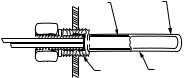
The sensors may be mounted on a wall or panel for sensing space temperature, strapped to a pipe or inserted in an immersion well (see Fig. 2) for hot or cold water sensing, or taped to a standard cap or bulb holder for duct air sensing. To prevent moisture or condensation entering the sensor through the lead wire holes, mount the sensor with the lead wires exiting the bottom of the sensor.
NOTES:
1.The included sensor is not designed for very wet applications. For immersion applications, an immersion well is used.
2.Heat conductive compound must be used in immersion wells.
3.Refer to “Temperature Sensors” on page 2 for this type of installation.
Controller Mounting
IMPORTANT
Avoid mounting in areas where acid fumes or other deteriorating vapors can attack the metal parts of the controller circuit board, or in areas where escaping gas or other explosive vapors are present.
IMPORTANT
The controller must be mounted in a position that allows clearance for wiring, servicing, and removal.
Use a screwdriver to pry out only the knockouts that you will use.
If mounting on DIN rail, be sure to remove the knockouts before mounting. See “Controller Wiring” on page 5 and Fig. 7 on page 6 for recommended knockout usage and locations. If you do not use an opened knockout be sure to cover it.
SENSOR |
USE HEAT |
PLACED |
CONDUCTIVE |
IN WELL |
COMPOUND |
1/2 NPT |
IMMERSION |
|
WELL |
|
M24470 |
Fig. 2. Sensor Inserted in Immersion Well.
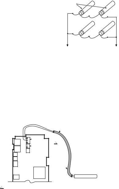
NOTE: Multiple sensors may be parallel-series wired to sense average temperatures in large spaces. Refer to Fig. 3 on page 4.
WIRING
All wiring must comply with applicable electrical codes and ordinances, or as specified on installation wiring diagrams. Controller wiring is terminated to the screw terminal blocks located inside the device.
The remainder of this section describes the temperature sensor wiring and the T775A/B/M controller wiring.
3 |
62-0254—05 |
T775A/B/M SERIES 2000 ELECTRONIC STAND-ALONE CONTROLLERS
Wiring Connections Access
To access the wiring connections, remove the two screws on the left side of the enclosure and gently swing open the top. Be careful to not stress the ribbon cables that connect the keypad and LCD display to the controller circuit board.
Multiple Parallel Sensors
Multiple sensors can be parallel-series wired to sense average temperatures in large spaces. To maintain control accuracy, the number of sensors to be parallelseries wired must be of the n2 power (for example, 4, 9, 16, etc.) (See Fig. 3).
Temperature Sensor Wiring
 CAUTION
Electrical Shock Hazard.
Can short equipment circuitry.
Make sure that metal tube of sensor does not short against T terminals in wall-mounted case.
IMPORTANT
Poor wiring practices can cause erratic readings from the sensor. Avoid the following to ensure proper operation:
•Do not route the temperature sensor wiring with building power wiring.
•Do not locate the temperature sensor wiring next to control contactors.
•Do not locate the temperature sensor wiring near electrical motors.
•Do not locate the temperature sensor wiring near welding equipment.
•Make sure good mechanical connections are made to both the sensor and the controller.
•Do not mount the sensor with the lead wire end pointing up in an area where condensation can occur.
If any of the above conditions cannot be avoided, use shielded cable.
NOTE: Each T775 controller must be wired to its own sensor(s). However, a benefit of the T775 controller’s accuracy is that there is no more than a 2° F (-7° C) differential between any two T775 controllers.
SENSORS
TO T775 CONNECTIONS (SENSOR A) OR (SENSOR B).
M24471
Fig. 3. Parallel-Series Wiring of Sensors.
Temperature Sensor Wire Type and Size
Temperature sensors use standard AWG 18/2 unshielded wire. For cable runs greater than 25 feet or where electrical interference may be a problem, shielded cable is recommended (See Fig. 4).
Refer to “Temperature Sensor Calibration” on page 10 for wire size selection where cable runs are longer than 25 feet.
 SHIELDED
CABLE
T
 SENSOR A
 T
T
1
 T
T  SENSOR B
 T
T
SHIELDED
CABLE 
1 SENSOR A AND SENSOR B TERMINAL WIRING IS POLARITY INSENSITIVE.
NOTE: SHIELDED CABLE MUST BE CONNECTED TO AN EARTH GROUND.
HOWEVER, DO NOT GROUND SHIELDED CABLE AT SENSOR END.
SENSOR
NOTE: TO MINIMIZE NOISE PICKUP,
MAKE SENSOR CONNECTION FROM SHIELDED CABLE AS CLOSE AS POSSIBLE TO SENSOR BODY.
M24472
Fig. 4. Sensor Wiring — Showing Shielded Cable Connection to Sensor A.
62-0254—05 |
4 |
T775A/B/M SERIES 2000 ELECTRONIC STAND-ALONE CONTROLLERS
Controller Wiring
 WARNING
Electrical Shock Hazard.
Can cause severe injury, death or property damage.
Disconnect power supply before beginning wiring, or making wiring connections, to prevent electrical shock or equipment damage.
See Fig. 7 on page 6 for locating the appropriate power input, remote sensors input, low voltage, contact closure, and load output terminals.
Access to the terminals can be gained through standard conduit knockouts (A through E in Fig. 7 on page 6) located around the perimeter of the enclosure:
•Knockouts A and B should be used only for sensor and low-voltage wiring.
•Knockouts C, D, and E can be used to gain access to the load relay output terminals and 120/240 Vac power wiring.
 CAUTION
Do not use 24 Vac power to power any external loads if 120 Vac or 240 Vac is used to power the T775A/B/M controller.
 CAUTION
A separate earth ground is required.
Equipment damage can result if the earth ground is not connected. See Fig. 5 and Table 2 on page 6.
 CAUTION
Equipment Damage Hazard.
Electrostatic discharge can short equipment circuitry.
Ensure that you are properly grounded before handling the unit.
|
1 |
W |
C + |
|
2 |
1NO HIGH VOLTAGE. CLASS 2 WIRING ONLY.
2EARTH GROUND TERMINAL MUST BE CONNECTED TO CONDUIT CLAMP LOCALLY.
M24296
Fig. 5. Earth Ground.
IMPORTANT
Poor wiring practices can cause erratic readings from the sensor. To ensure proper operation, ensure that good mechanical connections are made to both the sensor and the controller.
IMPORTANT
When wiring the input power, only one source of power can be applied to the T775A/B/M controller (24 Vac or 120 Vac or 240 Vac).
Controller Wiring Method
Wire the sensors and outputs, then wire the power connection.
Each terminal can accommodate the following gauges of wire:
•Single wire – from 14 AWG to 22 AWG solid or stranded
•Multiple wires – up to two 22 AWG stranded
For 24, 120, or 240 Vac power connections:
• Single wire – from 14 to 18 AWG solid or stranded
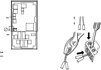
Prepare wiring for the terminal blocks, as follows:
1.Strip 1/2 in. (13 mm) insulation from the conductor.
2.Cut a single wire to 3/16 in. (5 mm). Insert the wire in the required terminal location and tighten the screw.
3.If two or more wires are being inserted into one terminal location, twist the wires together a minimum of three turns before inserting them to ensure proper electrical contact.
4.Cut the twisted end of the wires to 3/16 in. (5 mm) before inserting them into the terminal and tightening the screw.
5.Pull on each wire in all terminals to check for good mechanical connection.
1. STRIP 1/2 IN. (13 MM) |
|
|
|
FROM WIRES TO |
|
|
|
BE ATTACHED AT |
1/2 (13) |
|
|
ONE TERMINAL. |
|
|
|
|
|
|
|
2. TWIST WIRES TOGETHER WITH PLIERS (A MINIMUM OF THREE TURNS).
3.CUT TWISTED END OF WIRES
TO 3/16 IN. (5 MM) BEFORE INSERTING
INTO TERMINAL AND TIGHTENING SCREW.
THEN PULL ON EACH WIRE IN ALL
TERMINALS TO CHECK FOR
GOOD MECHANICAL CONNECTION.
M24473
Fig. 6. Attaching Two or More Wires at Terminal Blocks.
5 |
62-0254—05 |
T775A/B/M SERIES 2000 ELECTRONIC STAND-ALONE CONTROLLERS
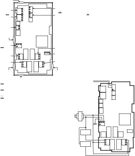
Controller Wiring Details
The wiring connection terminals are shown in Fig. 7 and are described in Table 2.
See Fig. 8 – Fig. 20 beginning on page 6 for typical T775A/B/M wiring applications.
KNOCKOUT A |
|
|
|
|
|
|
|
|
B |
T |
|
|
SENSOR A |
|
MOD 1 |
T |
|
|
||
|
|
|
|
|||
|
R – |
|
|
|
1 |
|
|
2 |
W + |
T |
|
|
|
|
|
|
SENSOR B |
|||
|
MOD 2 |
B |
T |
|
|
|
|
|
|
|
|||
|
R – |
|
|
|
|
|
|
|
|
|
|
|
|
|
|
W + |
|
|
|
|
|
DIGITAL |
– |
|
|
|
|
|
+ |
|
|
|
|
|
|
INPUT |
|
|
|
|
|
KNOCKOUT B |
|
|
|
|
|
|
3 |
POWER |
C + |
|
|
|
|
|
24 VAC |
|
|
|
|
OUTPUT |
|
|
|
|
|
|
RELAY 3 |
|
OUTPUT |
NC |
NC |
|
|
POWER |
|
RELAY 4 |
<![if ! IE]> <![endif]>120 |
<![if ! IE]> <![endif]>COM 240 |
120/240 VAC |
||
|
C |
C |
||||
|
|
|
||||
|
|
NO |
NO |
|
||
|
OUTPUT |
NO |
|
NO |
|
OUTPUT |
|
|
|
RELAY 2 |
|||
|
RELAY 1 |
C |
|
C |
|
|
|
|
|
|
|||
|
|
NC |
|
NC |
|
|
KNOCKOUT C |
|
|
|
|
KNOCKOUT D |
|
 KNOCKOUT E
1SENSORS A AND B USE THE TWO TT CONNECTIONS AND ARE POLARITY INSENSITIVE.
2FOR MOD 1 AND MOD 2 CURRENT (mA) OR VOLTAGE (VDC) OUTPUT, USE SIGNAL (+) & COMMON (-).
FOR MOD 1 AND MOD 2 SERIES 90 OUTPUT, USE W, R, & B.
3A SEPARATE EARTH GROUND IS REQUIRED FOR ANY POWER
SOURCE (24, 120, OR 240 VAC). |
M24474 |
Table 2. Description of Wiring
Terminal Connections. (Continued)
Connection |
Terminal Label |
Description |
|
Input |
|
DI |
+ - |
Digital Input (dry |
|
|
contact) |
|
24 Vac Power |
|
24V + |
+ |
24 Vac Hot |
|
|
|
Common |
C |
24 Vac Common |
|
|
|
Ground |
|
Earth Groundb |
|
120 or 240 Vac |
Power |
120 Vac |
120 |
120 Vac Power |
|
|
|
Common |
COM |
Common |
|
|
|
240 Vac |
240 |
240 Vac Power |
|
|
|
aFor Series 90 connections, you must insert a 340 Ohm resistor across terminals R and W. Refer to Fig. 17 on page 8. The resistor is included with the controller.
bA separate earth ground is required for all installations regardless of the power source (24, 120, or 240 Vac). Refer to Fig. 5 on page 5.
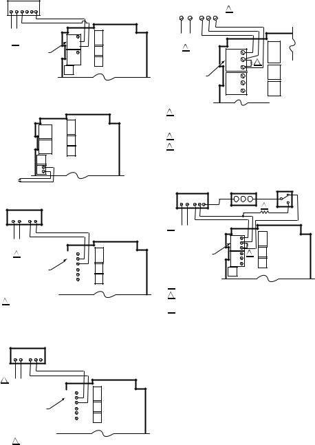
WIRING APPLICATIONS (EXAMPLES)
Fig. 8 – 20 illustrate typical controller wiring for various applications.
SENSOR A
 T
T
 T
T
Fig. 7. T775A/B/M Terminal and Feature Locations.
NOTE: Refer to Table 1 on page 1 for the specific configuration of sensors and outputs supported by the model you are installing.
NOTE: For NEMA 4 enclosures, use waterproof fittings for wiring/conduit connections at knockouts.
Table 2. Description of Wiring
Terminal Connections.
Connection |
Terminal Label |
Description |
|
Sensors |
|
Sensor A |
T T |
Temperature Sensor; |
|
|
polarity insensitive |
Sensor B |
|
|
|
|
|
|
|
|
|
Outputs |
|
Relay 1 |
|
|
Relay 2 |
NO |
120-240 Vac Relay |
Relay 3 |
COM |
Output |
Relay 4 |
NC |
|
Mod 1 |
+ - (Vdc or mA) |
Modulating Output |
|
W R B (Series 90)a |
|
Mod 2 |
L1 |
|
|
|
(HOT) |
|
|
|
24 VAC |
|
|
|
L2 |
|
|
|
|
|
C + |
|
LOAD 1 |
|
|
|
|
NO |
NO |
NO |
|
COM |
||
|
C |
C |
|
LOAD 2 |
|
||
|
NC |
NC |
|
|
|
|
COM |
|
|
|
NO |
M24475A
Fig. 8. Wiring for Two-Stage Control – 24 Vac Input and 24 Vac Load.
62-0254—05 |
6 |

T775A/B/M SERIES 2000 ELECTRONIC STAND-ALONE CONTROLLERS
SENSOR A
 T
T
 T
T
L1 |
|
|
|
|
(HOT) |
|
|
|
|
24 VAC |
|
|
|
|
L2 |
|
|
|
|
|
|
C + |
|
|
LOAD |
COM |
NC |
NC |
|
4 |
||||
C |
C |
|||
|
NO |
|||
|
NO |
NO |
||
|
|
|||
LOAD |
NO |
NO |
NO |
|
1 |
COM |
|||
C |
C |
|||
|
|
|||
|
|
NC |
NC |
|
LOAD |
COM |
|
|
|
2 |
NO |
|
|
|
LOAD |
COM |
|
|
|
NO |
|
|
||
3 |
|
|
||
|
|
|
M24476A
Fig. 9. Wiring for Four-Stage Control – 24 Vac Input and 24 Vac Load.
SENSOR A
 T
T
 T
T
|
C + |
|
|
|
120V |
|
|
|
|
|
COM |
|
NC |
|
NC |
|
1 |
COM |
|
<![if ! IE]> <![endif]>120 COM 240 |
LOAD |
||
C |
|
C |
|||
NO |
NO |
|
NO |
3 |
|
|
NO |
NO |
|
NO |
LOAD |
|
COM |
|
|||
|
C |
|
C |
2 |
|
|
|
|
|||
|
|
NC |
|
NC |
|
LOAD 1
LOAD 4
1 FOR 240 VAC LOAD, CONNECT TO 240 TERMINAL.
M24478A
Fig. 11. Wiring for Four-Stage Control with 120 or 240 Vac (120 Vac Input and 120 Vac Load Shown).
SENSOR A
 T
T
 T
T
C + |
|
|
|
|
120V |
|
|
|
|
|
|
|
|
|
1 |
|
COM |
|
|
|
|
|
|
|
|
|
|
|
L1 (HOT) |
|
|
|
|
<![if ! IE]> <![endif]>120 COM 240 |
POWER SUPPLY |
|
|
|
|
L2 |
|
|
|
|
|
|
|
NO |
NO |
NO |
|
|
|
COM |
|
NO |
|
||
C |
C |
|
LOAD 2 |
||
|
|
||||
|
NC |
NC |
|
COM |
|
|
|
|
|
|
LOAD 1 |
|
|
|
|
|
1 |
FOR 240 VAC LOAD, CONNECT TO 240 TERMINAL. |
M24477A |
|
|
|
|
|
Fig. 10. Wiring for Two-Stage Control with 120 or 240 Vac (120 Vac Input and 120 Vac Load Shown).
|
|
|
120/240 VAC LINE |
|
1 |
|
2 |
DEVICE |
|
NO |
NO |
NO |
|
|
COM |
OPEN |
|||
C |
C |
|||
NC |
NC |
|
COM |
|
|
|
|
BARCODE
 CLOSE
CLOSE
COM
NO
1CLOSE RELAY TO DRIVE DEVICE OPEN. RELAY 1 SHOWN. (RELAYS 1 AND 3 ARE USED FOR OPEN).
2CLOSE RELAY TO DRIVE DEVICE CLOSED. RELAY 2 SHOWN. (RELAYS 2 AND 4 ARE USED FOR CLOSE).
THE RELAYS MUST BE WIRED IN PAIRS WITH RELAYS 1 AND 2
BEING THE FIRST PAIR, AND RELAYS 3 AND 4 BEING THE SECOND PAIR.
M24479
Fig. 12. Wiring for Floating Output (Relay 1 and Relay 2 Pair Shown).
7 |
62-0254—05 |
T775A/B/M SERIES 2000 ELECTRONIC STAND-ALONE CONTROLLERS
ML7984 ACTUATOR
T1 T2 C B R W
POWER
OUTPUT
1
MODULATING OUTPUT TERMINAL (MOD 1)
B
R –
W +
B
R –
W +
M27228
Fig. 13. Wiring for ML7984 Valve Actuator (Using 4 to 20 mA Signal).
DIGITAL |
– |
INPUT |
+ |
|
M24482
Fig. 14. Wiring for Digital Input (Dry Contact).
HONEYWELL MODUTROL MOTOR WITH 4-20 mA MODULATING INPUT
T1 T2 – +
POWER
OUTPUT
1 |
|
|
|
B |
||
|
|
|
|
R – |
||
MODULATING OUTPUT |
|
|
|
W + |
||
|
|
|
B |
|||
TERMINAL (MOD 1) |
|
|
|
R – |
||
|
|
|
|
W + |
||
|
|
|
|
|
|
|
|
|
|
|
|
|
|
1 USE SEPARATE TRANSFORMER FOR T775R WHEN USING 24 VAC.
M24481
Fig. 15. Wiring for Mod Motor or Direct Coupled Actuator with 4 to 20 mA Control Input.
HONEYWELL MODUTROL MOTOR WITH
VOLTAGE CONTROL INPUT
T1 T2 C R F
1 POWER OUTPUT
|
|
|
|
B |
||
|
|
|
|
R – |
||
MODULATING OUTPUT |
|
|
|
W + |
||
|
|
|
B |
|||
TERMINAL (MOD 1) |
|
|
|
R – |
||
|
|
|
|
W + |
||
|
|
|
|
|
|
|
|
|
|
|
|
|
|
1 USE SEPARATE TRANSFORMER FOR T775R WHEN USING 24 VAC.
M24483
Fig. 16. Wiring for Mod Motor or Direct Coupled Actuator with 0 to 10 Vdc Control Input.
HONEYWELL ELECTRONIC
SERIES 90 MODUTROL MOTOR
T1 T2 B R W |
1 |
|
|
|
|
POWER |
|
|
OUTPUT |
|
|
2 |
B |
|
|
|
|
|
R – |
3 |
|
W + |
|
|
|
|
MODULATING |
B |
|
OUTPUT |
R – |
|
TERMINAL |
|
|
(MOD 1) |
W + |
|
1TO VERIFY OUTPUT, TEST OPEN CIRCUIT VOLTAGE BETWEEN THE MOD 1 TERMINALS W AND R.
-MINIMUM (DRIVE CLOSED) SIGNAL LESS THAN 0.17 VDC
-MAXIMUM (DRIVE OPEN) SIGNAL IS GREATER THAN 1.7 VDC
2USE SEPARATE TRANSFORMER FOR T775R WHEN USING 24 VAC.
3INSERT 340 OHM RESISTOR (INCLUDED) ACROSS TERMINALS R AND W.
M24484
Fig. 17. Wiring for Series 90 Modutrol Motor Control.
HONEYWELL |
MINIMUM POSITION |
|
ELECTRONIC SERIES 90 |
POTENTIOMETER |
|
MODUTROL MOTOR |
(Q209) |
|
T1 T2 B R W |
W R |
B |
|
|
|
|
|
2 |
1 POWER |
|
|
OUTPUT |
B |
|
|
|
|
|
R – |
|
|
W + |
|
MODULATING OUTPUT |
B |
3 |
TERMINAL (MOD 1) |
R – |
|
|
W + |
|
SPDT CHANGEOVER (H205 OR H705)
1USE SEPARATE TRANSFORMER FOR T775R WHEN USING 24 VAC.
2A 250 OHM RESISTOR PROVIDES 40% AUTHORITY WHEN USING A 150 OHM MINIMUM POSITION POTENTIOMETER.
3INSERT 340 OHM RESISTOR (INCLUDED) ACROSS TERMINALS R AND W.
M24485
Fig. 18. Wiring for Changeover Relay and Minimum Position Potentiometer Used with Series 90 Modutrol Motors.
62-0254—05 |
8 |
T775A/B/M SERIES 2000 ELECTRONIC STAND-ALONE CONTROLLERS
M9184 OR M9185 |
L1 |
1 |
|
L2 |
|||
MODUTROL MOTOR |
(HOT) |
||
|
|
|
R |
|
|
|
TR |
|
|
|
W |
|
|
|
TR |
|
B |
|
B |
|
|
2 |
||
R – |
|
||
3 |
M9184 OR M9185 |
||
W + |
MODUTROL MOTOR |
||
|
|||
B |
|
R |
|
R – |
|
TR |
|
W + |
|
||
|
W |
||
|
|
TR |
|
|
|
B |
|
|
|
M9184 OR M9185 |
|
MODULATING OUTPUT |
MODUTROL MOTOR |
||
|
|||
TERMINAL (MOD 1) |
R |
||
TR
W
TR
B
1POWER SUPPLY. PROVIDE DISCONNECT MEANS AND OVERLOAD PROTECTION AS REQUIRED.
2USE A 1300 OHM RESISTOR FOR TWO MOTORS, 910 OHM RESISTOR FOR THREE MOTORS. THE 407EAU RESISTOR KIT, WHICH IS SHIPPED WITH THE M9184 AND M9185 MOTORS, INCLUDES BOTH RESISTORS.
3 INSERT 340 OHM RESISTOR (INCLUDED) ACROSS TERMINALS R AND W. |
M24486 |
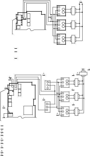
Fig. 19. Wiring for Three Series 90 Modutrol Motors.
3
B  9
9  R –
R – W +
W +
B
R –
W +
 –
–  +
+
8 POWER 24 VAC
 C +
C +
MODULATING OUTPUT TERMINAL (MOD 1)
|
|
L1 (HOT) |
L2 1 |
6 MINIMUM |
|
4 |
|
POSITION |
|
M9184 OR M9185 2 |
|
|
MODUTROL MOTOR |
|
|
POTENTIOMETER |
|
|
|
|
|
|
|
(Q209/S963) |
|
R |
|
W |
|
TR |
|
|
W |
|
|
R |
|
TR |
|
|
B |
|
|
|
|
|
|
B |
|
M9184 OR M9185 2 |
|
|
|
|
|
|
|
MODUTROL MOTOR |
|
|
|
R |
|
|
|
TR |
|
|
|
W |
|
5 CHANGEOVER |
|
TR |
|
|
B |
|
|
CONTROLLER |
|
|
|
1 W |
|
M9184 OR M9185 2 |
|
2 R |
|
MODUTROL MOTOR |
|
|
R |
|
|
3 B |
|
TR |
|
|
|
W |
|
|
7 |
TR |
|
|
B |
|
|
|
|
|
1POWER SUPPLY. PROVIDE DISCONNECT MEANS AND OVERLOAD PROTECTION AS REQUIRED.
2UP TO SIX SIMILAR MOTORS CAN BE CONNECTED IN UNISON.
3USE RESISTOR BETWEEN R AND B ON THE MOD 1 TERMINAL: 1300 OHMS FOR TWO MOTORS; 910 OHMS FOR THREE MOTORS (4074EAU KIT).
4IF COMMON TRANSFORMER IS USED, ALL MOTORS MUST BE IN PHASE. CONNECT THE SAME TRANSFORMER LEAD TO T1 ON EACH MOTOR, CONNECT THE OTHER TRANSFORMER LEAD TO T2 ON EACH MOTOR.
5USE TEMPERATURE CONTROLLER SUCH AS H205 OR H705, OR T675A FOR CHANGEOVER CONTROL.
6AUTHORITY OF MINIMUM POSITION POTENTIOMETER, IF USED, INCREASES WITH THE NUMBER OF MOTORS IN PARALLEL. WITH ONE MOTOR, 50% STROKE; WITH TWO MOTORS, 100% STROKE; WITH THREE MOTORS, 100% STROKE WITH 1/3 OF FULL POTENTIOMETER ROTATION.
7REVERSING THE B AND W TERMINALS ON ONE OR MORE MOTORS WILL NOT AFFECT CONTROL PERFORMANCE ON THE OTHER MOTORS. THE SYSTEM CAN BE CONFIGURED TO HAVE SOME MOTORS BE REVERSE ACTING AND OTHER MOTORS BE DIRECT ACTING.
8USE SEPARATE TRANSFORMER FOR T775 WHEN POWERING FROM 24 VAC.
9THE SYSTEM IS SHOWN CONNECTED FOR COOLING. FOR HEATING, REVERSE THE W AND B LEADS OF THE MODULATING OUTPUT ON THE T775 CONTROLLER.
M24487
Fig. 20. Wiring for Unison Control of M9184 or M9185 Modutrol IV Motor Using One Minimum Position Potentiometer for All Motors.
9 |
62-0254—05 |
T775A/B/M SERIES 2000 ELECTRONIC STAND-ALONE CONTROLLERS
CHECKOUT
Inspect all wiring connections at the controller terminals, and verify compliance with the installation wiring diagrams.
 WARNING
Electrical Shock Hazard.
Can cause severe injury, death or property damage.
Disconnect power supply before beginning wiring or making wiring connections, to prevent electrical shock or equipment damage.
If any wiring changes are required, first be sure to remove power from the controller before starting work. Pay particular attention to verifying the power connection (24, 120, or 240 Vac).
After the controller is installed and wired, apply power.
Power Loss
The date and time settings are retained for 24 hours after a power outage. After a power loss of more than 24 hours, the date and time settings may need to be reentered. All other settings are stored permanently.
Temperature Sensor Calibration
As wire length increases, resistance increases and thus the temperature reading increases. If necessary, calibrate the sensor input by reducing the value by the amount shown in the Table 3. For example, a wire run with 18 gauge wire of 1,000 feet, requires a calibration offset of -6.0° F (-21° C).
IMPORTANT
If the calibration value in the table exceeds the controller’s calibration limits of +/-10° F (+/-6° C), you must use a heavier gauge wire.
For example, with a wire run of 1,000 feet you must use 20 AWG wire or heavier in order to calibrate for wire loss within the limits of the controller.
See “2.2.2.2. CALIBRATE (the sensor)” on page 18 for the instructions to enter the calibration value.
Table 3. Temperature Sensor Calibration for Resistance Loss Due to Wire Length.
|
|
Temperature Offset in |
||
AWG |
|
|
°F (Foot)a |
|
Rating |
mΩ/ft |
200 ft |
500 ft |
1,000 ft |
14 |
2.5 |
0.46 |
1.14 |
2.28 |
16 |
4.0 |
0.72 |
1.82 |
3.64 |
|
|
|
|
|
18 |
6.4 |
1.16 |
2.90 |
5.82 |
|
|
|
|
|
20 |
10.2 |
1.86 |
4.64 |
9.28 |
|
|
|
|
|
22 |
16.1 |
2.92 |
7.32 |
14.64 |
|
|
|
|
|
|
|
|
|
|
|
|
Temperature Offset in |
||
AWG |
|
|
°C (Meter)a |
|
Rating |
mΩ/m |
100 m |
200 m |
300 m |
14 |
8.3 |
0.44 |
0.86 |
1.30 |
|
|
|
|
|
16 |
13.2 |
0.68 |
1.38 |
2.06 |
|
|
|
|
|
18 |
21.0 |
1.10 |
2.18 |
3.28 |
|
|
|
|
|
20 |
33.5 |
1.74 |
3.48 |
5.22 |
|
|
|
|
|
22 |
52.8 |
2.74 |
5.48 |
8.22 |
|
|
|
|
|
aThis is the distance from the controller to the sensor (already accounts for round trip distance).
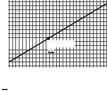
Fig. 21 shows how sensor resistance varies with temperature for a sensor having a positive temperature coefficient (PTC) of 2.1 Ohms per degree F (3.85 Ohms per degree C).
RESISTANCE (OHMS)
1489
1403
1317
1231
1145
1059 |
|
1097 ± 0.08 OHMS |
|
||
|
|
AT 77°F (25°C) |
|
|
|
|
|
|
973 |
1 |
|
|
887 |
|
801
-40 |
-20 |
0 |
20 |
40 |
60 |
80 |
|
100 |
120 |
140 |
160 |
180 |
200 |
220 |
|
250 °F |
||||||||||||||||
|
|
|
|
|
|
|
|
|
|
|
|
|
|
|
|
|
|
|
|
|
|
|
|
|
|
|
|
|
|
|
|
|
-40 |
-30 |
-20 |
-10 |
0 |
10 |
20 30 |
40 |
50 |
60 |
70 |
80 |
90 |
100 110 |
120 °C |
||||||||||||||||||
TEMPERATURE (DEGREES)
1 POSITIVE TEMPERATURE COEFFICIENT (PTC) OF 2.1 OHMS PER °F
M24304
Fig. 21. Sensor Resistance vs. Temperature.
62-0254—05 |
10 |
T775A/B/M SERIES 2000 ELECTRONIC STAND-ALONE CONTROLLERS
INTERFACE OVERVIEW
The T775A/B/M controllers use an LCD panel and 6-button keypad to provide status information and permit user input of the programming, setup, and scheduling parameters.
The following figure describes the display areas of the LCD and the keypad.
HOME
RELAYS 1 2 3 4 MENU AREA
ON
SENSORS |
|
|
SENSOR A |
|
|
78 |
oF |
|
|
|
|
SENSOR B |
|
|
84 |
oF |
|
|
DATA AREA |
|
|
|
|
MOD1 |
40% |
|
MOD2 |
60% |
LOCK ICON |
DI ON |
|
|
|
|
|
home |
menu |
|
|
|
6 BUTTON KEYPAD |
|
|
M24488 |
Fig. 22. LCD Display - Home Screen And Keypad.
Menu Area – On the home screen, the LCD displays the configured relays and whether they are active. In Program, Setup or Schedule mode, the LCD displays the current menu selection and its order within the menu hierarchy.
Data Area – On the home screen, the LCD displays the sensors and outputs status. In Setup or Program mode, the LCD displays menu choices, parameter selections, and data values.
Lock Icon – The icon indicates the MENU button is locked and prevents access to the Setup and Program menus.
NOTE: Pressing and holding the HOME and MENU buttons simultaneously for five seconds locks/ unlocks the MENU button.
6-Button Keypad – The keypad is used to access the menus and enter values (See “Using the LCD Panel Interface”).
Using the LCD Panel Interface
The 6-button keypad is used to move through the menus and enter or change parameter values.
Home Button
Pressing the HOME button at any time exits the current Programming or Setup display screen and returns to the home screen as shown in Fig. 22 and Fig. 23.
Menu Button
•Pressing the MENU button always displays the Program menu. If you are in Setup mode, you exit setup and return to the Program menu.
•Pressing and holding the MENU button for five seconds leaves the current screen and displays the Setup menu.
Left and Right Arrow Buttons (W and X)
Use these buttons to move backward (W) and forward (X) through the Program and Setup menus.
Up and Down Arrow Buttons (S and T)
Use these buttons to move your selection up and down through a menu or list.
•When the desired item is highlighted, you press the X arrow button to display that item’s content.
•When a value is displayed (e.g. 70° F), the up and down arrows increase and decrease the value.
NOTE: Once you select an item from a list or enter a value, pressing the W or X or HOME button accepts your selection or value and stores it in the controller’s memory.
Home Screen
In the normal run state, the LCD home screen displays the current sensed temperatures, the modulating outputs status, the active status of the output relays, and error and status codes.
Active relays are indicated by the small black square ( ) just below the relay number. Fig. 23 shows the home screen with relays 1, 2, and 4 energized.
Pressing the W and X buttons from the home screen cycles through each modulating output that is paired with the sensor it controls and the active output relays.
HOME |
|
|
HOME |
|
|
|
|
|
HOME |
|
|
|
|
||
RELAYS 1 2 3 4 |
|
RELAYS 1 2 3 4 |
|
RELAYS 1 2 3 4 |
|||||||||||
ON |
|
|
ON |
|
|
|
|
|
ON |
|
|
|
|
||
SENSORS |
|
|
MOD 1 |
40% |
|
REL 1 |
ON |
||||||||
SENSOR A |
|
|
COOL |
|
|
|
|
|
HEAT |
|
|
|
|
||
78 |
|
oF |
|
SETPOINT |
|
|
|
|
|
SETPOINT |
|
|
|
|
|
SENSOR B |
|
|
74 |
|
|
oF |
|
60 |
|
oF |
|||||
84 |
|
oF |
|
SENSOR A |
|
|
|
|
|
SENSOR A |
|
|
|
|
|
|
|
|
|
62 |
|
|
oF |
|
62 |
|
oF |
||||
|
|
|
|
|
|
|
|
|
|
|
RT 12345 HRS |
||||
|
|
|
|
|
|
|
|
|
|
|
|
|
|
|
|
MOD1 |
40% |
|
MOD1 |
40% |
|
|
|
MOD1 |
40% |
|
|
||||
MOD2 |
60% |
|
MOD2 |
60% |
|
|
|
MOD2 |
60% |
|
|
||||
DI ON |
|
|
|
DI ON |
|
|
|
|
|
|
DI ON |
|
|
|
|
|
|
|
|
|
|
|
|
|
|
|
|
|
|
|
|
|
|
|
|
|
|
|
|
|
|
|
|
|
|
|
|
M24489
Fig. 23. LCD Display - Home Screen Displaying Sensors, Active Relays, and Mod Outputs.
NOTE: The modulating output home screen and the relay home screen do not dynamically update the active relay status, sensor values, and modulating output percentages. The information is a snapshot taken when you press the W or X button to display the screen.
IMPORTANT
After four minutes of inactivity (no buttons pressed), the LCD display reverts to the home screen display.
11 |
62-0254—05 |
Loading...