


HCG40D
Table of contents
 Loading...
DGC1, HGC40, HGC60,
GAS CONVECTION OVENS
HGC40D & HGC60D
GAS CONVECTION OVENS
MODELS
DGC1 ML-43853
HGC40 ML-43856
HGC40D ML-43859
HGC60 ML-114731
HGC60D ML-114732
701 S. RIDGE AVENUE
TROY, OHIO 45374-0001
FORM 19240 Rev. D (3-98)
IMPORTANT FOR YOUR SAFETY
THIS MANUAL HAS BEEN PREPARED FOR PERSONNEL QUALIFIED TO INSTALL GAS
EQUIPMENT, WHO SHOULD PERFORM THE INITIAL FIELD START-UP AND
ADJUSTMENTS OF THE EQUIPMENT COVERED BY THIS MANUAL.
POST IN A PROMINENT LOCATION THE INSTRUCTIONS TO BE FOLLOWED IN THE
EVENT THE SMELL OF GAS IS DETECTED. THIS INFORMATION CAN BE OBTAINED
FROM THE LOCAL GAS SUPPLIER.
IMPORTANT
IN THE EVENT A GAS ODOR IS DETECTED, SHUT
DOWN UNITS AT MAIN SHUTOFF VALVE AND
CONTACT THE LOCAL GAS COMPANY OR GAS
SUPPLIER FOR SERVICE.
FOR YOUR SAFETY
DO NOT STORE OR USE GASOLINE OR OTHER
FLAMMABLE VAPORS OR LIQUIDS IN THE
VICINITY OF THIS OR ANY OTHER APPLIANCE.
WARNING
IMPROPER INSTALLATION, ADJUSTMENT,
ALTERATION OR MODIFICATION, SERVICE OR
MAINTENANCE CAN CAUSE PROPERTY
DAMAGE, INJURY OR DEATH. READ THE
INSTALLATION, OPERATING AND MAINTENANCE
INSTRUCTIONS THOROUGHLY BEFORE
INSTALLING OR SERVICING THIS EQUIPMENT.
IN THE EVENT OF A POWER FAILURE, DO NOT
ATTEMPT TO OPERATE THIS DEVICE.
© HOBART CORPORATION, 1993
– 2 –

TABLE OF CONTENTS
GENERAL. . . . . . . . . . . . . . . . . . . . . . . . . . . . . . . . . . . . . . . . . . . . . . . . . . . . . . . . . . . . . . . . . . . . . . 4
INSTALLATION . . . . . . . . . . . . . . . . . . . . . . . . . . . . . . . . . . . . . . . . . . . . . . . . . . . . . . . . . . . . . . . . . 4
Unpacking. . . . . . . . . . . . . . . . . . . . . . . . . . . . . . . . . . . . . . . . . . . . . . . . . . . . . . . . . . . . . . . . 4
Location . . . . . . . . . . . . . . . . . . . . . . . . . . . . . . . . . . . . . . . . . . . . . . . . . . . . . . . . . . . . . . . . . 4
Leveling . . . . . . . . . . . . . . . . . . . . . . . . . . . . . . . . . . . . . . . . . . . . . . . . . . . . . . . . . . . . . . . . . 5
Installation Codes and Standards . . . . . . . . . . . . . . . . . . . . . . . . . . . . . . . . . . . . . . . . . . . . . 5
Installing Basic Oven . . . . . . . . . . . . . . . . . . . . . . . . . . . . . . . . . . . . . . . . . . . . . . . . . . . . . . . 5
Assembling the Legs to the Oven . . . . . . . . . . . . . . . . . . . . . . . . . . . . . . . . . . . . . . . . . . . . . 6
Assembling the Chimney and Flue Extension . . . . . . . . . . . . . . . . . . . . . . . . . . . . . . . . . . . 6
Assembling Stacked Ovens. . . . . . . . . . . . . . . . . . . . . . . . . . . . . . . . . . . . . . . . . . . . . . . . . . 6
Assembling the Oven to the Stand . . . . . . . . . . . . . . . . . . . . . . . . . . . . . . . . . . . . . . . . . . . . 7
Electrical Connections . . . . . . . . . . . . . . . . . . . . . . . . . . . . . . . . . . . . . . . . . . . . . . . . . . . . . . 8
Gas Connections . . . . . . . . . . . . . . . . . . . . . . . . . . . . . . . . . . . . . . . . . . . . . . . . . . . . . . . . . . 8
Testing the Gas Supply System . . . . . . . . . . . . . . . . . . . . . . . . . . . . . . . . . . . . . . . . . . . . . . 8
Burner Air Shutter Adjustments. . . . . . . . . . . . . . . . . . . . . . . . . . . . . . . . . . . . . . . . . . . . . . . 9
Flue Connections . . . . . . . . . . . . . . . . . . . . . . . . . . . . . . . . . . . . . . . . . . . . . . . . . . . . . . . . . . 9
Before First Use . . . . . . . . . . . . . . . . . . . . . . . . . . . . . . . . . . . . . . . . . . . . . . . . . . . . . . . . . . . 9
OPERATION . . . . . . . . . . . . . . . . . . . . . . . . . . . . . . . . . . . . . . . . . . . . . . . . . . . . . . . . . . . . . . . . . . 10
Controls — Models DGC1 and HGC40/HGC60 . . . . . . . . . . . . . . . . . . . . . . . . . . . . . . . . . 10
Lighting the DGC1 and HGC40/HGC60 Ovens . . . . . . . . . . . . . . . . . . . . . . . . . . . . . . . . . 11
Using the DGC1 and HGC40/HGC60 Ovens . . . . . . . . . . . . . . . . . . . . . . . . . . . . . . . . . . . 11
Controls — Model HGC40D/HGC60D . . . . . . . . . . . . . . . . . . . . . . . . . . . . . . . . . . . . . . . . 12
Lighting the HGC40D/HGC60D Oven. . . . . . . . . . . . . . . . . . . . . . . . . . . . . . . . . . . . . . . . . 16
Using the HGC40D/HGC60D Oven . . . . . . . . . . . . . . . . . . . . . . . . . . . . . . . . . . . . . . . . . . 16
Error Messages — HGC40D/HGC60D Oven . . . . . . . . . . . . . . . . . . . . . . . . . . . . . . . . . . . 17
Cook and Hold Operation . . . . . . . . . . . . . . . . . . . . . . . . . . . . . . . . . . . . . . . . . . . . . . . . . . 18
Proper Utensils. . . . . . . . . . . . . . . . . . . . . . . . . . . . . . . . . . . . . . . . . . . . . . . . . . . . . . . . . . . 19
Conserving Energy. . . . . . . . . . . . . . . . . . . . . . . . . . . . . . . . . . . . . . . . . . . . . . . . . . . . . . . . 19
Operating Hints . . . . . . . . . . . . . . . . . . . . . . . . . . . . . . . . . . . . . . . . . . . . . . . . . . . . . . . . . . 19
Cleaning . . . . . . . . . . . . . . . . . . . . . . . . . . . . . . . . . . . . . . . . . . . . . . . . . . . . . . . . . . . . . . . . 19
Cooking Guidelines . . . . . . . . . . . . . . . . . . . . . . . . . . . . . . . . . . . . . . . . . . . . . . . . . . . . . . . 20
MAINTENANCE . . . . . . . . . . . . . . . . . . . . . . . . . . . . . . . . . . . . . . . . . . . . . . . . . . . . . . . . . . . . . . . . 22
Replacing Lamps . . . . . . . . . . . . . . . . . . . . . . . . . . . . . . . . . . . . . . . . . . . . . . . . . . . . . . . . . 22
TROUBLESHOOTING. . . . . . . . . . . . . . . . . . . . . . . . . . . . . . . . . . . . . . . . . . . . . . . . . . . . . . . . . . . 23
– 3 –

Installation, Operation and Care of
DGC1, HGC40 & HGC40D GAS CONVECTION OVENS
SAVE THESE INSTRUCTIONS FOR FUTURE USE
GENERAL
The Model DGC1 Oven is equipped with a mechanical thermostat and 1-hour dial timer; the Model
HGC40 and HGC60 Ovens are equipped with a solid state thermostat with probe and 1-hour dial
timer; and the Model HGC40D and HGC60D Ovens feature an electronic thermostat, electronic timer,
a cook-and-hold function and a pulse control. Each oven is equipped with five racks, a two-speed
1
⁄2 H.P. blower motor and a 40,000 BTU/hr. burner as standard equipment, and requires a 120 volt
single phase electrical service. The doors open independently.
Models HGC60 and HGC60D have a deeper oven cavity.
A single oven is furnished with a set of four 25
Stacked ovens are furnished with a set of four 8" (203mm) adjustable painted or stainless steel legs,
and a stacking kit for mounting one oven on top of the other.
A single oven installed on a storage stand is furnished with four 6" (152mm) adjustable painted or
stainless steel legs.
Additional racks are available as accessories. The porcelain interior is standard. A stainless steel
interior is available as an option.
3
/4" (654mm) adjustable painted or stainless steel legs.
INSTALLATION
UNPACKING
Immediately after unpacking the oven, check for possible shipping damage. If this oven is found to be
damaged, save the packaging material and contact the carrier within 15 days of delivery.
Prior to installation, verify that the electrical service and type of gas (natural or propane) agree with the
specifications on the oven data plate, located on the inside of the bottom front cover.
Do not use the doors or their handle to lift the oven.
LOCATION
The equipment area must be kept free and clear of combustibles. Maintain clearances from
combustible or non-combustible construction for at least 6" (152mm) from the side and 6" (152mm)
from the back of the oven. The installation location must allow adequate clearances for servicing and
proper operation.
The oven must be installed so that the flow of combustion and ventilation air will not be obstructed.
Adequate clearance for air openings into the combustion chamber must be provided. Make sure there
is an adequate supply of air in the room to allow for that required for combustion of gas at the oven
burners.
– 4 –
LEVELING
Ensure that the oven racks are level in the final installed position.
INSTALLATION CODES AND STANDARDS
Hobart ovens must be installed in accordance with:
In the United States
1. State and local codes.
2. National Fuel Gas Code ANSI-Z223.1 (latest edition), available from American Gas Association,
1515 Wilson Boulevard, Arlington, VA 22209.
3. ANSI/NFPA 96, "Vapor Removal from Cooking Equipment" (latest edition), available from National
Fire Protection Association, Batterymarch Park, Quincy, MA 02269.
4. National Electrical Code, ANSI/NFPA-70 (latest edition).
In Canada
1. Local codes.
2. CAN/CGA-B149.1, "Natural Gas Installation Code" (latest edition).
3. CAN/CGA-B149.2, "Propane Installation Code" (latest edition) available from the Canadian Gas
Association, 178 Rexdale Blvd., Etobicoke, Ontario, Canada M9W 1R3.
4. Canadian Electrical Code, CSA Standard C22.2 No. 3 (latest edition).
INSTALLING BASIC OVEN
The basic oven must be installed on legs or be mounted on a modular stand. Installations on concrete
bases or other supports restricting air circulation underneath the oven is not advisable and may void
the warranty.
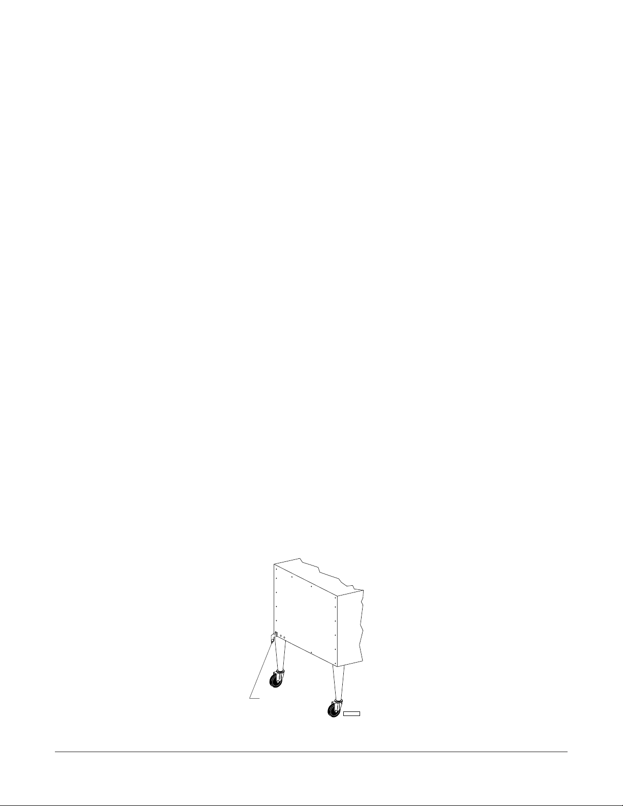
NOTICE: When the oven is mounted on casters, it must be installed with the casters supplied, a
connector (not supplied by Vulcan-Hart) complying with either ANSI Z21.69 (latest edition) or
CAN/CGA-6.16 (latest edition), and a quick-disconnect device complying with either ANSI Z21.41
(latest edition) or CAN1-6.9 (latest edition). It must also be installed with restraining means to guard
against transmission of strain to the connector, as specified in the appliance manufacturer’s instructions.
Attach the restraining device at the rear of the oven (Fig. 1).
CONNECT GAS
LINE STRAIN
RELIEF HERE
Fig. 1
– 5 –
PL-51216
ASSEMBLING THE LEGS TO THE OVEN
Unpack the oven and leg set.
Position oven on its back, taking care not to scratch or damage it. The gas pipe connection protrudes
beyond the back; provide for this when oven is tipped back by resting it on suitable spacers (2 x 4's etc.).
Attach each of the four leg assemblies to the bottom of the oven with the 24 bolts and lockwashers
(6 per leg).
Carefully raise the oven to its normal position. Turn the adjustable feet in or out to level the oven front-
to-back and side-to-side.
ASSEMBLING THE CHIMNEY AND FLUE EXTENSION
Remove the oven chimney and flue extension from the rear of the oven (motor compartment) and use
the screws provided to fasten the chimney to the top rear of the oven. The flanges on the chimney are
to be positioned under the top cover. Also attach the flue extension.
ASSEMBLING STACKED OVENS
Unpack the ovens and stack kit. Position one oven on its back for access to the oven bottom, taking
care not to scratch or damage it. The gas pipe protrudes beyond the back; provide for this when the
oven is tipped back by resting it on suitable spacers (2 x 4's, etc.). Attach the four leg assemblies with
the 24 bolts and lockwashers (6 per leg).
Place the lower oven (with legs) on the floor and remove the two
7
/16" (11.1mm) diameter knockouts on
each side of the top cover.
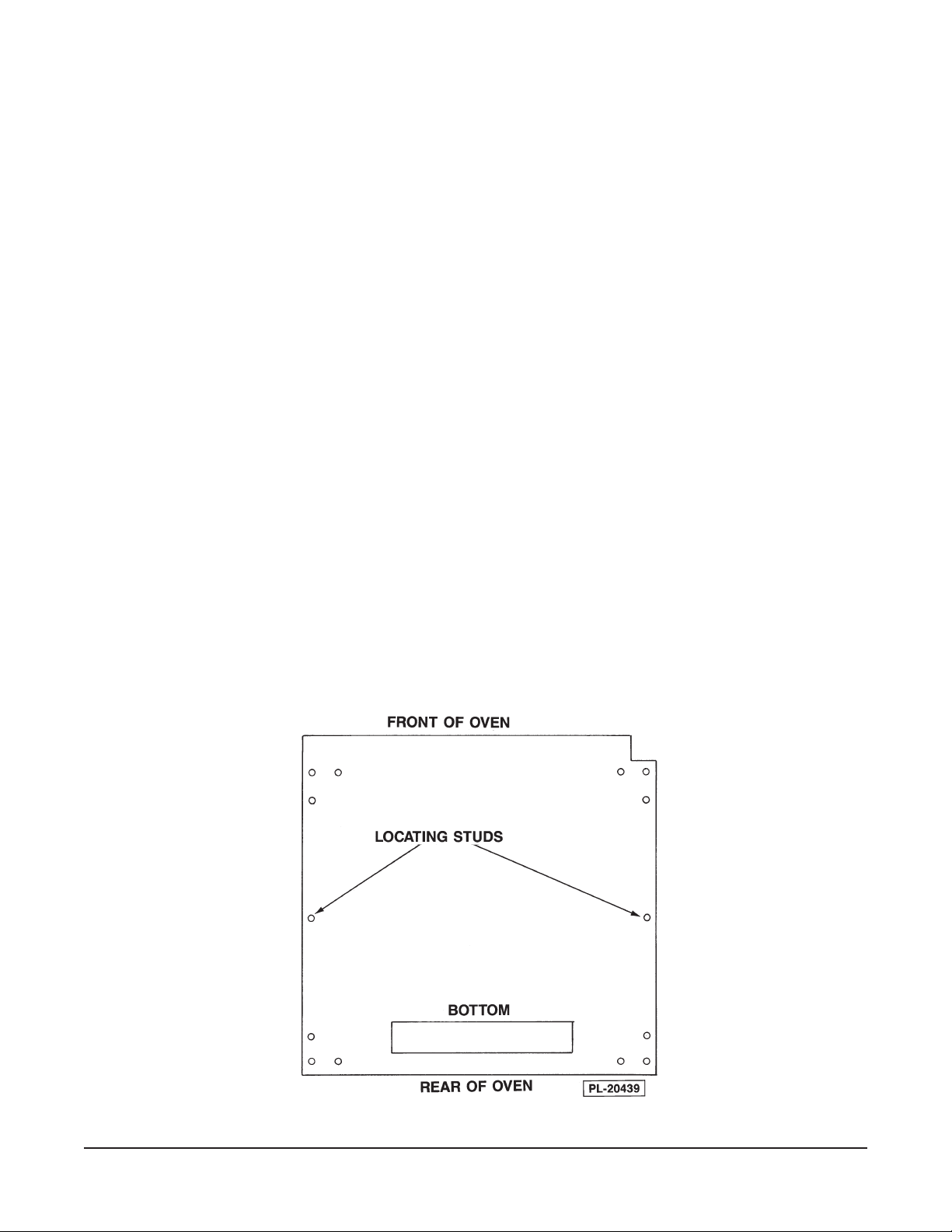
Install the two locating studs (included in the leg stack set) into the screw plates on the underside of
the upper oven (Fig. 2).
Fig. 2
– 6 –
Move the oven with legs to the installed position and place the upper oven on top of the lower oven using
the locating studs.
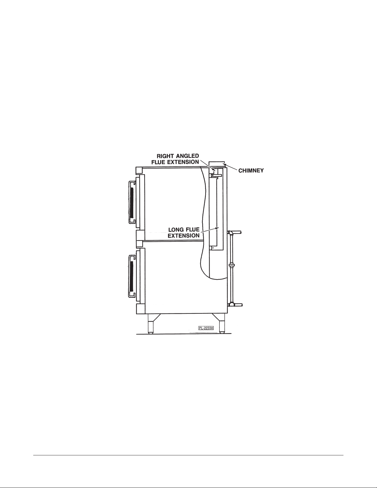
Remove the rear panels from both ovens. Remove the right angle flue extension (Fig. 3) from the top
oven.
Insert the right angle short flue extension into the top oven. Install the long flue extension (Fig. 3) from
the stack kit over the right angle flue extension on the top oven. Insert the right angle of the long flue
extension into the bottom oven. Secure the flue extensions with the screws provided.
Install rear panels on both ovens. Install chimney (Fig. 3) on upper oven. Connect the piping between
the top oven and bottom oven. Pipe compound must be suitable for the type of gas being used (natural
or propane).
The manual gas valve at the bottom of the control panel should remain off until all electrical connections
are made and the ovens are checked or used.
Fig. 3
ASSEMBLING THE OVEN TO THE STAND
Unpack the oven and stand. Position oven on its back, taking care not to scratch or damage it. The
gas pipe connection protrudes beyond the back; provide for this when the oven is tipped back by resting
it on suitable spacers (2 x 4's, etc.).
Install the two locating studs (included in the stand carton) into the screw plates on the underside of
the oven (see Fig. 2).
Attach each of the four leg assemblies to the bottom of the stand with the 24 bolts and lockwashers
(6 per leg).
Mount the oven on top of the stand.
– 7 –
ELECTRICAL CONNECTIONS
WARNING: THE POWER CORD IS PROVIDED WITH A GROUNDING PLUG. THE OUTLET TO
WHICH THIS PLUG IS CONNECTED MUST BE PROPERLY GROUNDED. IF THE RECEPTACLE IS
NOT THE PROPER GROUNDING TYPE, CONTACT AN ELECTRICIAN. DO NOT REMOVE THE
GROUNDING PRONG FROM THIS PLUG.
Your gas convection oven is equipped with a 120 volt / 60 Hz. / 1 phase cord and plug and requires
only that it be plugged into a properly grounded 120 volt receptacle.
A wiring diagram is located on the inside of the right side panel.
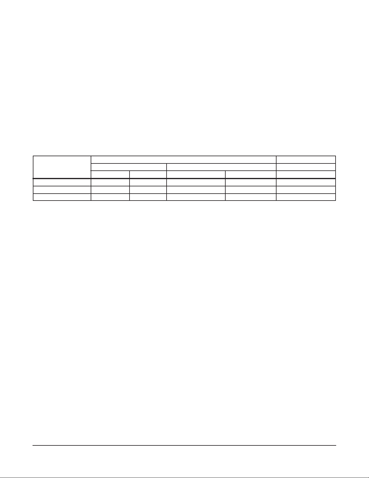
GAS AND ELECTRICAL DATA
GAS DATA ELECTRICAL DATA
MODEL INPUT BTU/HR MANIFOLD PRESSURE AMP/LINE
Natural Propane Natural Propane 120 Volts
DGC1 40,000 40,000 3.5" W.C. (0.8 kPa) 10" W.C. (2.5 kPa) 10 Amps
HGC40/HGC60 40,000 40,000 3.5" W.C. (0.8 kPa) 10" W.C. (2.5 kPa) 10 Amps
HGC40D/HGC60D 40,000 40,000 3.5" W.C. (0.8 kPa) 10" W.C. (2.5 kPa) 10 Amps
Stacked ovens require double BTU/Hr and double amperage.
GAS CONNECTIONS
Gas supply connections and pipe joint compound must be suitable for sealing piping for propane or
natural gases.
The oven is provided with a regulator integral to the gas solenoid valve and requires no external
regulator.
The manual gas shutoff valve is located at the bottom of the front control panel.
The oven should be connected to the gas line after leveling. The gas supply line must be at least the
equivalent of
3
/4" (19mm) iron pipe. Make sure piping is clean and free of obstructions, dirt or pipe joint
compound.
WARNING: PRIOR TO LIGHTING, CHECK ALL JOINTS IN THE GAS SUPPLY LINE FOR LEAKS.
USE SOAP AND WATER SOLUTION. DO NOT USE AN OPEN FLAME.
TESTING THE GAS SUPPLY SYSTEM
The oven and its individual shutoff valve must be disconnected from the gas supply piping system
during any pressure testing of that system at test pressures greater than
1
/2 psig (3.45 kPa).
The oven must be isolated from the gas supply piping system by closing the manual shutoff valve during
pressure testing of the gas supply piping system at test pressures equal to or less than 1/2 psig (3.45 kPa).
– 8 –
Loading...