


 Loading...
A200 MIXER
TECHNICAL MANUAL (ML-104858) (115/60/3)
SPECIFICATION SHEET INSTALLATION INSTRUCTIONS OPERATION INSTRUCTIONS CLEANING INSTRUCTIONS MAINTENANCE INSTRUCTIONS TROUBLE SHOOTING INSTRUCTIONS WIRING DIAGRAMS
CATALOG OF REPLACEMENT PARTS SMARTPARTS™ USER GUIDE RECOMMENDED SPARE PARTS LIST

Need other Hobart Services?
•Warranty Registration
•Delivery and Installation
•Preventive Maintenance
•Hobart Service Contracts
•Extended Warranty Contracts
•Parts and Accessories
•Specialty Programs
•Water Treatment Programs
•Air Filtration System
A200 Mixer 115/60/1 Technical ManualPage 2 of 43

Item # ________________________________
Quantity _______________________________
C.S.I. Section 11400
|
|
|
|
|
|
|
|
A-200 |
|
|
FOOD EQUIPMENT |
|
MIXER |
|
|
|
|
|
|
|
|
|
|
|
|
|
|
|
|
|
|
|
|
|
STANDARD FEATURES
1⁄2 H.P. Hobart Designed Fixed Speed Motor
Gear-Driven Transmission
15 Minute Timer
Three Fixed Speeds
Open Base
Large, Easy-To-Reach Controls
#12 Taper Attachment Hub
Stainless Steel Bowl Guard
Manual Bowl Lift
20-Quart Stainless Steel Bowl, “B” Flat Beater,
“D” Wire Whip, Cord and Plug
ACCESSORIES
Stainless Steel Bowl
“B” Flat Beater
Stainless Steel “B” Beater
“C” Wing Whip
“D” Wire Whip
“E” Dough Hook
“ED” Dough Hook
“P” Pastry Knife
Bowl Splash Cover
Bowl Scraper
12 Quart Accessories
Ingredient Chute
9" Vegetable Slicer
Meat Chopper Attachment
MODEL
A-200 – 20-Quart All Purpose Mixer
A-200C – 20-Quart All Purpose Mixer with
Maximum Security Correctional Package (115/60/1, Bench Model only)
OPTIONS
Deluxe Nickel Chrome Plate Finish (115/60/1 and 230/60/1, Bench Model only)
Floor Model
(Base is 21"W x 211⁄2"D x 411⁄4"H)
Specifications, Details and Dimensions on Inside and Back.
R
200-A MIXER
701 S Ridge Avenue, Troy, OH 45374 • 937-332-3000 • 1-800-333-7447
A200 Mixer 115/60/1 Technical ManualPage 3 of 43

A-200 MIXER
FOOD EQUIPMENT
SOLUTIONS/BENEFITS
1⁄2 H.P. Hobart Designed Motor
Durability
■Heavy-duty to meet the most demanding operations
15-Minute Electric Timer
Convenience, Ease of Use, Consistency
■Supports recipe mixing times
■Simplifies operation
■Provides accurate results and eliminates overmixing
Three Fixed Speeds
Flexibility, Reliability, Consistency
■For incorporating, blending, mixing ingredients
■Supports consistent results and thorough mixing
Bowl Guard
Protection
■Safety interlock prevents operation when front portion of guard is out of position
Gear-Driven Transmission
Durability, Reliability
■Ensures consistent performance and minimum downtime with positive drive under heavy loads
Hobart Attachments
Durability, Flexibility
■Hobart manufactured accessories are designed for long-term usage under heavy-duty conditions
■Large array of attachments provide multiple uses for recipe and product processing
A-200 MIXER CAPACITY CHART
Recommended Maximum Capacities - dough capacities based on 70°F. water and 12% flour moisture.
|
|
AGITATORS |
|
PRODUCT |
|
SUITABLE FOR |
A-200 |
|
|
OPERATION |
|
CAPACITY OF BOWL (QTS. LIQUID) |
20 |
||
Egg Whites |
|
D |
1 qt. |
Mashed Potatoes |
|
B & C |
15 lbs. |
Mayonnaise (Qts. of Oil) |
|
B or C or D |
10 qts. |
Meringue (Qts. of Water) |
|
D |
11⁄2 pts. |
Waffle or Hot Cake Batter |
|
B |
8 qts. |
Whipped Cream |
|
D or C |
4 qts. |
Cake, Angel Food |
|
|
|
(8-10 oz. cake) |
|
C or I |
15 |
Cake, Box or Slab |
|
B or C |
20 lbs. |
Cake, Cup |
|
B or C |
20 lbs. |
Cake, Layer |
|
B or C |
20 lbs. |
Cake, Pound |
|
B |
21 lbs. |
Cake, Short (Sponge) |
|
C or I |
15 lbs. |
Cake, Sponge |
|
C or I |
12 lbs. |
Cookies, Sugar |
|
B |
15 lbs. |
Dough, Bread or Roll |
|
|
|
(Lt.-Med.) 60% AR |
§ |
ED |
25 lbs.■ |
Dough, Heavy Bread 55% AR |
§ |
ED |
15 lbs.■ |
Dough Pie |
|
B & P |
18 lbs. |
Dough, Thin Pizza 40% AR |
|
|
|
(max. mix time 5 min.) |
§‡ |
ED |
9 lbs.■ |
Dough, Med. Pizza 50% AR |
§‡ |
ED |
10 lbs.■ |
Dough, Thick Pizza 60% AR |
§‡ |
ED |
20 lbs.■ |
Dough, Raised Donut 65% AR |
|
ED |
9 lbs.* |
Dough, Whole Wheat 70% AR |
|
ED |
20 lbs. |
Eggs & Sugar for Sponge Cake |
B & C or I |
8 lbs. |
|
Icing, Fondant |
|
B |
12 lbs. |
Icing, Marshmallow |
|
C or I |
2 lbs. |
Shortening & Sugar, Creamed |
|
B |
16 lbs. |
Pasta, Basic Egg Noodle |
|
|
|
(max. mix time 5 min.) |
|
ED |
5 lbs. |
NOTE: % AR (% Absorption Ratio) - Water weight divided by
flour weight. Capacity depends on moisture content of dough. Above capacities based on 12% flour moisture at 70°F water temperature.
■ 1st Speed
* 2nd Speed
§If high gluten flour is used, reduce above dough batch size by 10%.
‡ 2nd Speed should never be used on 50% AR or lower products.
USE OF ICE REQUIRES A 10% REDUCTION IN BATCH SIZE.
1 gallon of water weighs 8.33 lbs.
NOTE: Attachment hub should not be used while mixing.
A200 Mixer 115/60/1 Technical ManualPage 4 of 43
FOOD EQUIPMENT
A-200 MIXER
SPECIFICATIONS
MOTOR:
1⁄2 H.P., Hobart designed, permanently lubricated ball bearings, splash-proof, fan cooled. Single-phase is capacitor-start, induction-run type.
Single Phase |
115V |
8.2 Amps |
|
230V |
4.2 Amps |
ELECTRICAL:
115/60/1 and 230/60/1 – U L Listed. Also available in 100/50/1, 220/50/1, 100/60/1 and 220/60/1 – not submitted for U L Listing.
CONTROLS:
Two-pole toggle switch with No Volt Release.
A 15-minute electric timer is standard. Non-timed operation obtained by setting timer on “HOLD” position.
TRANSMISSION:
Gear-driven. Gears are constant mesh heat-treated alloy steel. Anti-friction ball bearings. A hardened steel worm and special worm wheel transmit power from motor to transmission. Grease lubricated.
SPEEDS:
Three positive speeds - Low, Intermediate, and High.
|
Agitator |
Attachment |
|
(RPM) |
(RPM) |
|
|
|
Low |
107 |
61 |
|
|
|
Intermediate |
198 |
113 |
|
|
|
High |
361 |
205 |
|
|
|
BOWL GUARD:
Heavy-duty stainless steel wire front and solid stainless steel rear portion. Front portion of guard rotates easily to add ingredients and install or remove agitator. It detaches in seconds for cleaning in dishwasher or sink. Rear portion of guard can be quickly cleaned in position. Guard must be in closed position before mixer will operate. The bowl support lock prevents the bowl from being lowered while mixer
is running. Bowl support interlock provides further protection.
BOWL LIFT:
Hand crank operated, self-locking in any position.
FINISH:
Standard Metallic Gray finish, Polyurethane Enamel. Deluxe finish has nickel-chrome plating on transmission case, bowl support, pedestal and base.
STANDARD EQUIPMENT:
Consists of the mixer unit with cord and plug, one
(1) 20-quart stainless steel bowl, one (1) “B” flat beater, one (1) “D” wire whip, stainless steel bowl guard, cord and plug.
ATTACHMENT HUB:
When specified, comes with front-mounted Hobart standard #12 taper attachment hub for use with #12 size attachments.
NOTE: Use of attachment hub during mixing operation may result in a negative impact on performance and longevity of mixer.
ATTACHMENTS AND ACCESSORIES:
The following are available at extra cost:
Stainless Steel Bowl |
Bowl Splash Cover |
“B” Flat Beater |
Bowl Scraper |
Stainless Steel “B” Beater |
12 Quart Accessories |
“C” Wing Whip |
Ingredient Chute |
“D” Wire Whip |
9" Vegetable Slicer |
“E” Dough Hook |
Meat Chopper |
“ED” Dough Hook |
Attachment |
“P” Pastry Knife |
|
Hobart Bowl
Scraper
Hobart Ingredient
Chute
LISTED BY: Underwriters Laboratories, Inc. and the National
Sanitation Foundation.
A200 Mixer 115/60/1 Technical ManualPage 5 of 43

A-200 MIXER
FOOD EQUIPMENT
SPECIFICATIONS
ELECTRICAL SPECIFICATIONS: 115/60/1 and 230/60/1 – U L Listed. Also available in 100/50/1, 220/50/1, 100/60/1 and 220/60/1 – not submitted for U L Listing.
WEIGHT: 204 lbs. net; 226 lbs. domestic shipping. Floor Model: 230 lbs. net; 296 lbs. domestic weight.
WARRANTY: Unit has full one-year warranty on parts, labor and mileage against manufacturer’s defects. Service contracts are available.
DETAILS AND DIMENSIONS
A200/A200-T Mixers
WARNING
ELECTRICAL AND GROUNDING CONNECTIONS MUST COMPLY WITH
THE APPLICABLE PORTIONS OF THE NATIONAL ELECTRICAL CODE
AND/OR OTHER CODES IN FORCE.
A200FT Mixer
WARNING
ELECTRICAL AND GROUNDING CONNECTIONS MUST COMPLY WITH
THE APPLICABLE PORTIONS OF THE NATIONAL ELECTRICAL CODE AND/
OR OTHER CODES IN FORCE.
As continued product improvement is a policy of Hobart, specifications are subject to change without notice.
701 S Ridge Avenue, Troy, OH 45374 • 937-332-3000 • 1-800-333-7447
A200 Mixer 115/60/1 Technical ManualPage 6 of 43
F-7598 (REV. 6/01) LITHO IN U.S.A. (H-01)
Printed On Recycled Paper

I N
S
TRUCT
I ONS
A200 MIXER
MODEL
A200 ML-104859 (without Timer)
ML-104858 (with Timer)
ML-104863 (Deluxe Finish with Timer)
ML-104861 (Floor Model with Timer)
701 S. RIDGE AVENUE
TROY, OHIO 45374-0001
937 332-3000
www.hobartcorp.com |
FORM 34387 (Feb. 2000) |
A200 Mixer 115/60/1 Technical ManualPage 7 of 43
MODEL A200 MIXER
– 2 –
A200 Mixer 115/60/1 Technical ManualPage 8 of 43

Installation, Operation, and Care of
A200 MIXER
SAVE THESE INSTRUCTIONS
GENERAL
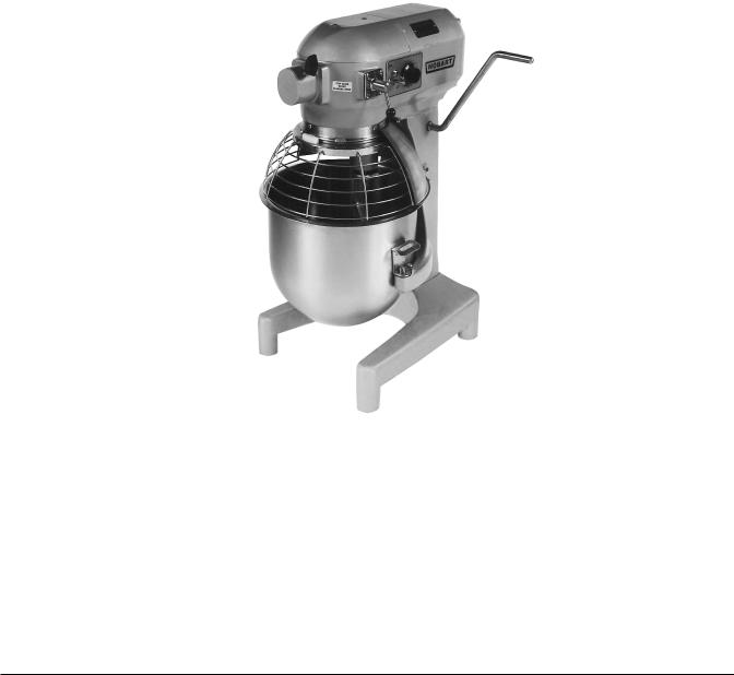
The model A200 mixer is a 20 quart, bench-type mixer with a 1/2 H.P. motor, and a #12 attachment hub. With the use of special agitators, a 12 quart bowl may be used on the A200 mixers.
The floor model and the deluxe finish model are equipped with a timer.
Most A200 mixers are equipped with a 0 - 15 minute timer.
There are a variety of attachments and accessories available for all models, and these are explained in a separate Use and Applications Handbook which is supplied with each mixer.
INSTALLATION
UNPACKING
Immediately after unpacking the mixer, check for possible shipping damage. If this machine is found to be damaged after unpacking, save the packaging material and contact the carrier within 15 days of delivery.
Prior to installation, test the electrical service to assure that it agrees with the specifications on the machine data plate.
LOCATION
Place the mixer on a suitable sturdy level surface. There should be adequate space around the mixer for the user to operate the controls and install and remove bowls.
Holes are provided in the base to permanently secure the mixer, although this is not necessary in normal installations. Four plastic plugs are supplied with the mixer to plug these holes if they are not used.
ELECTRICAL CONNECTIONS (Cord Connected Mixers)
WARNING: THE ELECTRICAL CORD ON THIS MACHINE IS EQUIPPED WITH A THREE-PRONGED GROUNDING PLUG WHICH MUST BE CONNECTED TO A PROPERLY GROUNDED RECEPTACLE. IF THE RECEPTACLE IS NOT THE PROPER GROUNDING TYPE, CONTACT AN ELECTRICIAN. DO NOT REMOVE THE GROUNDING PRONG FROM THE PLUG.
– 3 –
A200 Mixer 115/60/1 Technical ManualPage 9 of 43

OPERATION
WARNING: MOVING BEATER IN BOWL. KEEP HANDS, CLOTHING, AND UTENSILS OUT WHILE IN OPERATION, DO NOT USE WITHOUT INTERLOCKED GUARD.
CONTROLS
All models are furnished with an On-Off toggle switch which controls power to the mixer.
The Bowl Guard must be in position or the mixer will not operate. Refer to page 6.
If the Bowl Support is not all the way up, the mixer will not operate unless the On-Off switch is held in the up position.
The TIMER (if equipped) is used in conjunction with the On-Off switch for timed mixing operations and will stop the mixer when the desired time has elapsed.
With the timer set on HOLD, the mixer will run until the On-Off switch is turned to Off.
The GEAR SHIFT LEVER (Fig. 1) is used to change speeds. Always stop the mixer before changing speeds. To change speeds, turn the switch Off, move the gear shift lever to the desired speed, and turn the switch back On.
Speed 1 (Low) — This speed is for heavy mixtures such as bread dough, heavy batters, and potatoes.
Speed 2 (Medium) —This speed is for light dough which must rise quickly, cake batters, and some whipping operations.
Speed 3 (High) — This is a fast speed for light work such as whipping cream, beating eggs, and mixing thin batters.
The BOWL LIFT HANDLE (Fig. 1) is used to raise and lower the bowl. To raise the bowl, rotate the handle upward; rotating the handle downward lowers the bowl.
MIXING
This section explains operation of the mixer and how to install bowls, agitators, and attachments. A separate Use and Applications Handbook is provided with the mixer which contains information on mixing procedures and outlines specific uses for agitators, attachments, and accessories.
Bowl
New mixer bowls and agitators (beaters, whips, and dough arms) should be thoroughly washed with hot water and a mild soap solution, rinsed with either a mild soda or vinegar solution, and thoroughly rinsed with clear water BEFORE being put into service. This cleaning procedure should also be followed for bowls and agitators before whipping egg whites or whole eggs.
The bowl must be installed before the agitator. To install the bowl, fully lower the bowl support (Fig. 1). Position the bowl so the alignment bracket on the back of the bowl is in the bowl retainer and the alignment pins (Fig. 1) on the front of the bowl support fit in the holes on the sides of the bowl. Lock the bowl in place by rotating the bowl clamps (Fig. 1) over the ears of the bowl.
Agitator
To install an agitator (Fig. 1), the bowl must be installed and fully lowered. Place the agitator in the bowl, push it up on the agitator shaft, and turn it clockwise to seat the shaft pin in the slot of the agitator shank.
– 4 –
A200 Mixer 115/60/1 Technical ManualPage 10 of 43
A200 |
A200 WITH TIMER |
ON
OFF
ON 3 2 
1
OFF HOLD
4 |
5 |
6 |
7 |
|
|
8  9
9
10
11
 12
12

 13 15 14
ATTACHMENT HUB |
|
BOWL LIFT |
|
CONTROL |
HANDLE |
||
THUMB SCREW |
|||
PANEL |
|
||
|
|
||
GEAR SHIFT |
|
SPLASH |
|
|
GUARD |
||
LEVER |
|
||
|
|
||
|
|
APRON |
|
WIRE CAGE |
|
|
|
|
|
BOWL |
|
AGITATOR |
|
SUPPORT |
|
|
|
||
BOWL |
|
BOWL LIFT |
|
CLAMP |
|
||
|
SLIDEWAYS |
||
|
|
ALIGNMENT
PIN
PL-53477
Fig. 1
To Raise the Bowl While Mixing
To raise the bowl while the agitator is mixing the product (when required by recipe or when using the Bowl Scraper Attachment): Load ingredients. Close Wire Cage Assembly. Select Low speed. To begin mixing, hold the On-Off switch in the up position; then raise the bowl.
Attachments
To install an attachment, loosen the thumb screw on the attachment hub (Fig. 1) and remove the plug. Insert the attachment into the attachment hub making certain that the square shank of the attachment is in the square driver of the mixer. Secure the attachment by tightening the thumb screw.
Move the gear shift lever to the desired speed and start the mixer to operate the attachment.
The meat and food chopper attachment should be operated in second or third speed. If material in the cylinder stalls the mixer, stop the mixer at once. DO NOT attempt to restart the mixer in a lower speed
— remove the adjusting ring, knife, plate, and worm and clear the obstruction. THIS ATTACHMENT MUST NOT BE USED TO CHOP BREAD CRUMBS.
NOTE: Attachment hub should not be used while mixing.
Bowl Scraper Attachment
The Mixer Bowl Scraper Attachment (when ordered) is provided with a separate instruction manual covering its installation, operation, use and care.
– 5 –
A200 Mixer 115/60/1 Technical ManualPage 11 of 43
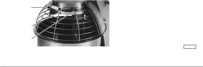
Bowl Guard (Fig. 2)
The Wire Cage Assembly on the Bowl Guard can be rotated out-of-the-way to add ingredients or access the bowl and agitator.
To rotate the Wire Cage Assembly to the rear . . .
Rotate the Wire Cage Assembly to the left until it is positioned underneath the Splash Guard. Note how the grooves on the nylon Retainers allow the Wire Cage to ride around the circular Ridge of the planetary Drip Cup.
The Wire Cage must be returned to the front and center position for the mixer to operate.
To remove the Wire Cage Assembly for cleaning . . .
Lower the Bowl. Rotate the Wire Cage Assembly to the left until it is positioned underneath the Splash Guard. Remove both Agitator and Bowl.
While holding the Wire Cage Assembly with both hands, rotate it completely to the left. When the frontcenter Retainer reaches the end of its travel, it can be lowered through the flat on the Ridge of the Drip Cup. After lowering the front-center Retainer, move the Wire Cage Assembly slightly to the rear so the Rear Retainers clear the Ridge on the Drip Cup. The Wire Cage Assembly can now be lowered and removed.
Wash the Wire Cage in a sink or dishwasher; rinse with clear water; and dry with a clean cloth.
The stainless steel Splash Guard can be wiped off or washed easily with a cloth or sponge and warm soapy water. Rinse with clear water. Dry with a clean cloth.
To reinstall the Wire Cage Assembly . . .
Hold the Wire Cage so its top ring is positioned around the planetary Drip Cup with the grooves in both nylon Rear Retainers straddling the Ridge on the Drip Cup at the rear. Lift the Wire Cage Assembly so the front-center Retainer passes up through the flat on the Ridge of the Drip Cup and rotate the Wire Cage Assembly to the right. The Wire Cage is properly assembled when all three Retainers straddle the Ridge on the Drip Cup in the three opposed locations. Rotate the Wire Cage Assembly to the right until it stops at the front-center position.
Rotate the Wire Cage out-of-the-way to install or remove the Agitator and Bowl or to add ingredients.
Return the Wire Cage to its front-center position to operate the mixer.
Front-Center
Retainer
Flat
Ridge -
Drip Cup
To Remove:
Rotate Wire Cage to the Left 340 Degrees until the Front-Center Retainer can be lowered through the Flat on the Ridge of the Drip Cup.
PL-40562-1
Fig. 2
– 6 –
A200 Mixer 115/60/1 Technical ManualPage 12 of 43

CLEANING
WARNING: UNPLUG MACHINE POWER CORD BEFORE BEGINNING ANY CLEANING PROCEDURE.
The mixer should be thoroughly cleaned daily.
Bowls and agitators should be removed from the mixer and cleaned in a sink.
DO NOT use a hose to clean the mixer — it should be washed with a clean damp cloth. The apron (Fig. 1) may be removed by loosening the thumb screws.
The Drip Cup-Splash Guard (which is secured by three screws) should be removed periodically and wiped clean.
For cleaning the Bowl Guard (including both Wire Cage Assembly and Splash Guard), refer to page 6.
MAINTENANCE
WARNING: UNPLUG MACHINE POWER CORD BEFORE BEGINNING ANY MAINTENANCE PROCEDURE.
LUBRICATION
Bowl Clamps (Fig. 1) should be lubricated twice a year.
Motor
The motor has sealed ball bearings which require no lubrication maintenance.
Bowl Lift Slideways
The slideways (Fig. 1) should be lubricated once each month. Remove the apron (Fig. 1) secured by two thumb screws to expose the slideways. Then apply a light coat of Lubriplate 630AA (supplied) to three sides of both slideways. Replace the apron and thumb screws.
– 7 –
A200 Mixer 115/60/1 Technical ManualPage 13 of 43
Loading...