


Hobart 6115 Installation Manual

MODEL 6115 POTATO PEELER
MODEL
ML-137600 6115 (with Timer)
701 S. RIDGE AVENUE
TROY, OHIO 45374-0001
937 332-3000
www.hobartcorp.com
FORM 37004 (Apr. 2006)

Installation, Operation and Care of
MODEL 6115 PEELER
SAVE THESE INSTRUCTIONS
GENERAL
The model 6115 Peeler is designed to peel 15 to 20 lb (7.0 to 9.0 kg) of product in 1 to 3 minutes using
1
/3 HP electric motor. The 6115 includes a 4-minute, synchronous timer which increments from 1/2 to 4
minutes and is a single-phase electrical service ONLY.
The peelers incorporate a reinforced peeling disc with abrasive permanently bonded to its surface and
a Lexan Liner for the inside of the hopper. The timer is mounted on the right side of discharge chute
as standard but can be ordered on the left or changed in the field. The bottom of peeler unit is cushioned
with a rubber trim molding which also provides a seal.
Optional accessories include a peel trap, a portable stand and a peel trap basket.
INSTALLATION
Immediately after unpacking, the machine should be checked for possible damage. If the machine is
found to be damaged after unpacking, save the packing material and contact the shipper.
This machine MUST be cleaned after installation and before being put into service. Refer to
MAINTENANCE for instructions.
PEELER UNIT (WITHOUT PEEL TRAP)
Remove the peeler unit from its shipping carton and remove the hopper top (Fig. 1). Remove the fill tube
and bracket assembly (Fig. 1), as well as the fill hose (Fig. 1) and clamp, from inside the peeler housing.
DO NOT remove the rubber molding on bottom of peeler.
Lay the peeler on its side and remove the bottom cover plate (Fig. 1) by removing the four screws.
Remove the corrugated packing material from between the motor and peeler housing. Replace the
bottom cover and set the machine upright.
The four acorn nuts (Fig. 1), for attaching the fill tube and bracket assembly, are threaded onto their
studs for shipment. Remove the four acorn nuts, leaving the gasket in place, and attach the fill tube and
bracket assembly.
Use pliers to depress the fill hose clamp and slide fill hose up onto the bottom of the fill tube.
If the optional portable stand is to be used, position peeler on top of stand and fasten it with the four
bolts (supplied). This completes installation for units without peel trap.
© HOBART CORPORATION, 1998
– 2 –
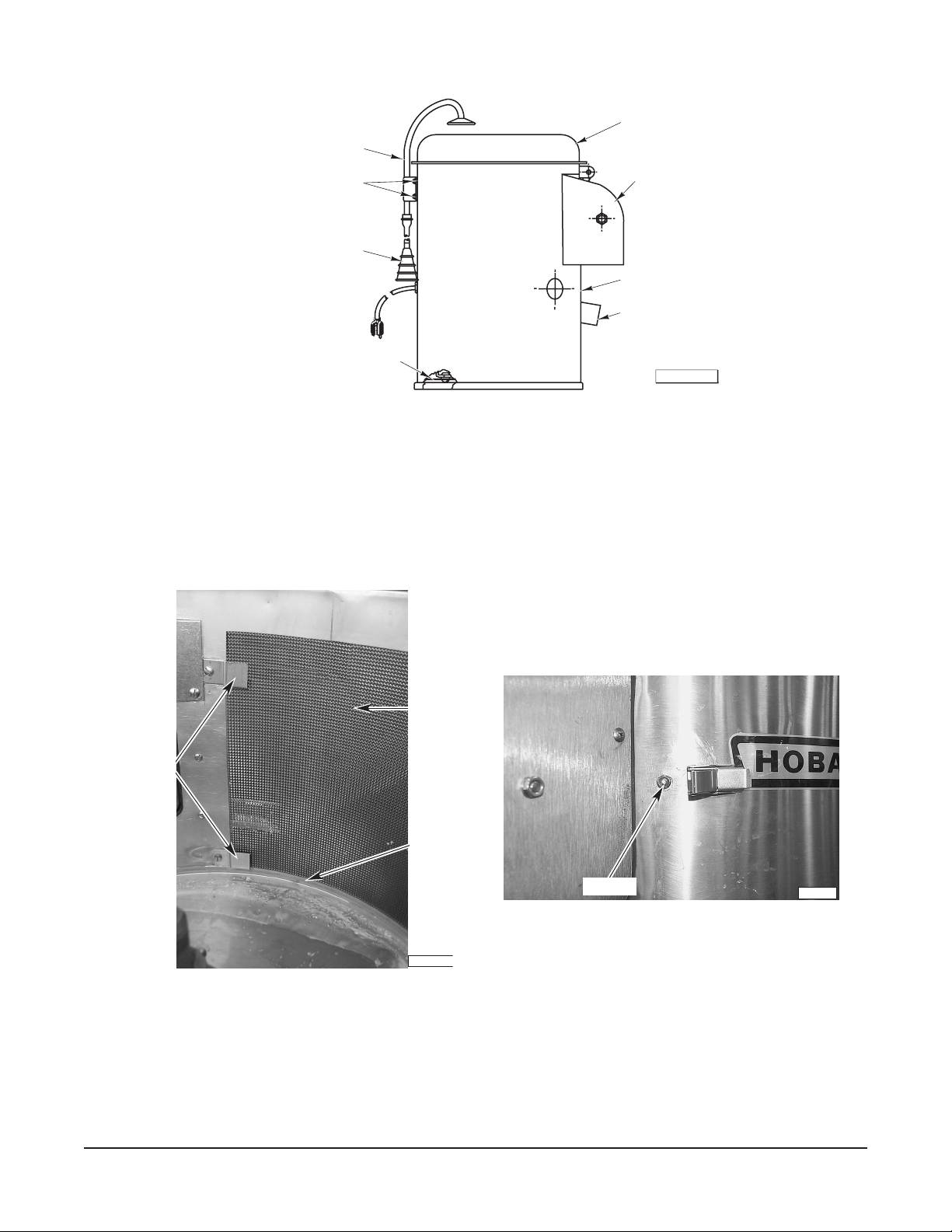
FILL TUBE AND
BRACKET ASSEMBLY
HOPPER TOP
ACORN NUT
FILL HOSE
BOTTOM COVER PLATE
DISCHARGE
CHUTE
DATA PLATE
DRAIN HOSE
PL-56484
Fig. 1
LEXAN LINER
1. Slide the liner (Fig. 2) into the hopper with the keeper to the right side (when viewed from the
discharge chute) of the discharge chute. Ensure the liner is under retaining brackets (Fig. 2) on
the left side of the discharge chute and resting on the top of the lip (Fig. 2) on the bottom of the
hopper chamber.
LINER
RETAINING
BRACKETS
LIP
PL-41652-1
Fig. 2 Fig. 3
2. Push the liner keeper into the hole (Fig. 3) provided.
3. Secure the keeper using the exterior latch.
KEEPER
PL-41653
– 3 –
PEELER UNIT (WITH PEEL TRAP)
If the unit is equipped with a peel trap basket, assemble basket per instructions on tag attached to the
basket.
Remove the peeler unit from its shipping carton and remove the hopper top (Fig. 1). Remove the fill tube
and bracket assembly (Fig. 1), as well as the fill hose (Fig. 1) and clamp, from inside the peeler housing.
DO NOT remove the rubber molding on bottom of peeler.
Lay the peeler on its side and remove the bottom cover (Fig. 1) by removing the four screws. Remove
the corrugated packing material from between the motor and peeler housing. Do not replace the bottom
cover.
Unpack the peel trap from its shipping carton. Remove the legs and the cloth bag from inside the peel
trap. The cloth bag contains hardware for attaching the legs.
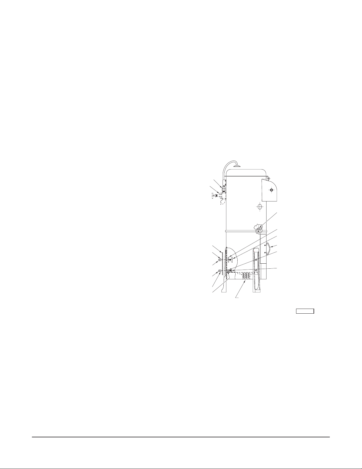
It will be necessary to remove the peel trap drawer (Fig. 4) to allow enough room for attaching the legs.
Assemble as follows (Fig. 4):
• Assemble one of the rubber gaskets to
one of the curved leg clamp bolts.
• Assemble bolt and gasket through one of
the upper leg bolt holes in peeler housing.
COUPLING
GLOBE VALVE
• Assemble a leg and a leg slot cover on the
leg clamp bolt.
• Place a stainless steel washer and acorn
nut onto the leg clamp bolt and partially
tighten nut.
• Assemble cap screw, washer and lead
washer.
• Place cap screw and washer through lower
leg bolt holes and slot cover.
• Place a stainless steel washer and acorn
nut onto cap screw and partially tighten.
SLOT COVER
WASHER
ACORN NUT
ACORN NUT
WASHER
LEAD WASHER
DRAIN CONNECTION
CAP SCREW
LOCKWASHER
WASHER
RUBBER GASKET
CLAMP BOLTS
PEEL TRAP DRAWER
WASHER
CAP SCREW
• Assemble each leg in this manner. When
all are assembled, set the unit upright.
Adjust each leg to a suitable height so the unit is
level, and tighten the acorn nuts.
Fig. 4
PL-56483
Set the peeler upside-down and, using a pair of pliers, squeeze the hose clip and remove the peeler
drain hose (Fig. 1). Replace this hose with the drain hose packed inside the peel trap.
The peeler may be positioned on the peel trap in one of four positions. Each of the positions will cause
the peel trap drawer to be located in a different position relative to the discharge chute.
The peel trap drawer may be directly beneath the discharge chute, to the right, left or rear (see Fig. 5).
After selecting the most convenient position for the peel trap drawer, remove the cover disc from the
appropriate hole in peel trap and position the peeler on top of the peel trap, with the peeler drain hose
extending through selected hole (Fig. 5).
– 4 –
 Loading...