


|
|
|
|
|
|
|
|
|
|
|
|
|
|
Model |
E40(3P)•E50(3P)•E57(3P)•E57(S3P) |
Generator |
||||
Мoдeль |
Генератор |
|||||
|
|
|
|
|
|
|
SAFETY INSTRUCTIONS AND INSTRUCTION MANUAL
 WARNING
Improper and unsafe use of this generator can result in death or serious bodily injury!
This manual contains important information about product safety. Please read and understand this manual before operating the generator. Please keep this manual available for other users and owners before they use the generator. This manual should be stored in safe place.
ИНСТРУКЦИЯ ПО БЕЗОПАСНОСТИ И ЭКСПЛУАТАЦИИ
 ВНИМАНИЕ
Hеправильнaя экcплуaтaция гeнeрaтoрa и нecoблюдeниe мeр бeзoпacнocти мoжeт привecти к ceрьeзным трaвмaм или cмeрти!
Дaннoepукoвoдcтвocoдeржитвcюнeoбxoдимуюинфoрмaциюпoмерамбезопаcнoсти прпработеcоборудованием.Внимательноознакомьтеcьcданнымруководcтвомперед началом работы c генератором. Пожалуйста, предоставьте другим пользователям даннуюинcтукцию,преждечемониначнутработатьcгенератором.Данноеруководство необходимо хранить в безопасном месте.

|
Contents |
English |
|
|
PAGE |
INTRODUCTION............................................................................................................................. |
3 |
MACHINE IDENTIFICATION.......................................................................................................... |
3 |
Safety............................................................................................................................................. |
4 |
Location of important labels........................................................................................... |
4 |
Operation and maintenance................................................................................................. |
5 |
CONTROL FUNCTION................................................................................................................... |
5 |
ENGINE SWITCH........................................................................................................................... |
6 |
AC NO-FUSE BREAKER (N.F.B).................................................................................................... |
6 |
APPLICATION RANGE................................................................................................................... |
7 |
SPECIFICATIONS........................................................................................................................... |
8 |
WIRING DIAGRAM......................................................................................................................... |
9 |
BATTERY TRAY INSTALLATION................................................................................................. |
11 |
HANGER KIT INSTALLATION...................................................................................................... |
11 |
|
ОГЛАВЛЕНИЕ |
|
Русский |
|
|
|
|
СТРАНИЦА |
Введение.................................................................................................................................. |
|
13 |
Информационные ярлыки............................................................................................... |
|
13 |
Требования по безопасности.......................................................................................... |
|
14 |
Расположение важных информационных ярлыков.......................................... |
14 |
|
Правила эксплуатации и обслуживания................................................................... |
15 |
|
Назначение элементов управления........................................................................... |
15 |
|
Выключатель зажигания................................................................................................ |
|
16 |
Автоматическое реле-прерыватель переменного тока.................................... |
16 |
|
Область применения.......................................................................................................... |
|
17 |
Технические характеристики........................................................................................ |
|
18 |
Схема электрической проводки.................................................................................. |
19 |
|
Установка поддона для аккумулятора.................................................................... |
21 |
|
МОНТАЖ КОМПЛЕКТА ПЕРЕНОСНОЙ РУКОЯТКИ.............................................................. |
21 |
|
English
INTRODUCTION
Thank you for purchasing HITACHI generator.
This supplementary instruction manual has been prepared to introduce the operation and maintenance of the “E40(3P), E50(3P), E57(3P), E40(S3P)”. Please read and understand this supplementary together with the enclosed E40, E50, E57, E57(S) instruction manual before operating the machine.
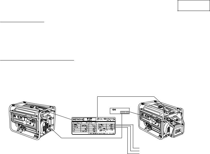
MACHINE IDENTIFICATION
The machine serial number is stamped in the location as shown.
NOTE: Keep a record of these numbers for reference when ordering parts from a HITACHI dealer.
E40(3P), E50(3P), E57(3P) |
E57(S3P) |
|
MACHINE SERIAL |
|
NUMBER |
CE AND |
E |
SER. NO |
|
GOST LABEL |
|
Maximum ambient temperature
Maximum altitude
Dry weight
Fig. 1
3
English
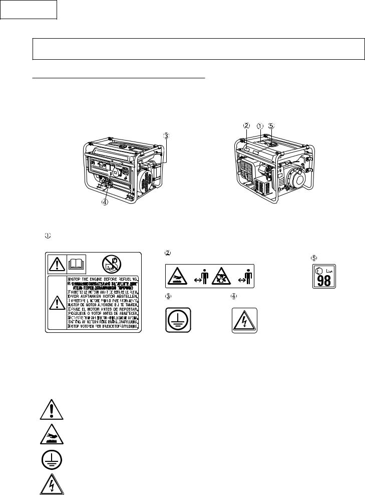
SAFETY
LOCATION OF IMPORTANT LABELS
NOTE: Maintain or replace safety and instruction labels, as necessary.
Fig. 2
READ INSTRUCTION |
|
|
CONNECT CAUTION |
|
|
FUEL CAUTION |
HOT CAUTION |
|
|
NOISE LABEL |
|
|
EXHAUST CAUTION |
|
|
|
|
|
|
|
|
|
|
|
|
|
|
|
|
|
|
|
|
|
|
|
|
|
|
|
|
|
|
|
|
|
|
|
|
|
|
|
|
|
|
|
|
|
|
|
|
|
|
|
|
|
|
|
|
|
|
|
|
|
|
|
|
|
|
|
|
|
|
|
|
|
|
|
|
|
|
|
|
|
|
|
|
|
|
|
|
|
|
|
|
|
|
|
|
|
|
|
|
|
|
|
|
|
|
|
|
|
|
|
GROUND (EARTH) |
|
ELECTRIC SHOCK |
|||||
|
|
|
|
|
|
|
|
|
|
|||||||
|
|
|
|
|
|
|
|
|
|
|||||||
|
|
|
|
|
|
|
|
|
|
|||||||
|
|
|
|
|
|
|
|
|
TERMINAL |
|
CAUTION |
|||||
|
|
|
|
|
|
|
|
|
|
|||||||
|
|
|
|
|
|
|
|
|
|
|||||||
Fig. 3
SYMBOL MEANING
Please understand the following symbols before operating this machine. (Refer to “SAFETY INFORMATION” for more details.)
The Safety Alert Symbol means ATTENTION! BECOME ALERT! YOUR SAFETY IS INVOLVED!
Avoid touching hot surfaces such as the engine and muffler.
Ground (earth) terminal.
Be sure to ground (earth) the generator.
Caution, risk of electric shock.
4
 User Manual")
English
OPERATION AND MAINTENANCE
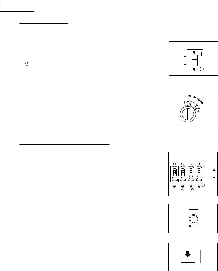
CONTROL FUNCTION
DESCRIPTION
E40(3P), E50(3P), E57(3P)
ENGINE SW |
PILOT |
AC VOLT METER |
1 ~ |
230V |
3 ~ 400V |
NO FUSE BRAKER |
STOP
TEST
Fig. 4
E57(S3P)
|
PILOT AC VOLT METER |
1 ~ 230V |
3 ~ 400V |
NO FUSE BRAKER |
|
STOP |
|
|
|
|
|
|
|
TEST |
|
Fig. 5 |
|
|
|
Fuel tank |
AC socket (for 3~) |
|
Pilot light |
|
Fuel tank cap |
Engine switch |
|
|
Voltage meter |
Fuel cock |
Ground (Earth) terminal |
|
AC circuit and leak breaker |
|
Air cleaner |
Oil filler cap |
|
|
(N.F.B.) |
Spark plug |
Oil drain plug |
|
|
Test button for leak breaker |
Muffler |
Recoil starter |
|
|
|
AC socket (for 1~) |
Fuel level gauge |
|
|
|
5
English
ENGINE SWITCH
The engine switch controls the ignition system.
 “ON”
“ON”
Ignition circuit is switched on. The engine can be started.
STOP “STOP”
Ignition circuit is switched off. The engine will not run.
 “START”
Starting circuit is switched on. The starter motor starts.
CAUTION: Take your hand off the switch immediately after the engine starts.
E40(3P), E50(3P), E57(3P)
ENGINE SW
STOP
Fig. 6
E57(S3P)

STOP |
|
Fig. 7
AC NO-FUSE BREAKER (N.F.B)
The AC NO-FUSE BREAKER turns off automatically when the load exceeds the generator rated output or leakage, and when leak exists in the output circuit.
 “ON”
“ON”
○ “OFF”
CAUTION: Reduce the load to the specified generator rated output if the AC (N.F.B) turns off. If it turns off again, consult your HITACHI dealer.
TEST BUTTON
Press the test button to check that the N.F.B. turns off.
 “ON”
“ON”
NO FUSE BRAKER
Fig. 8
TEST
Fig. 9
Fig. 10
6
English
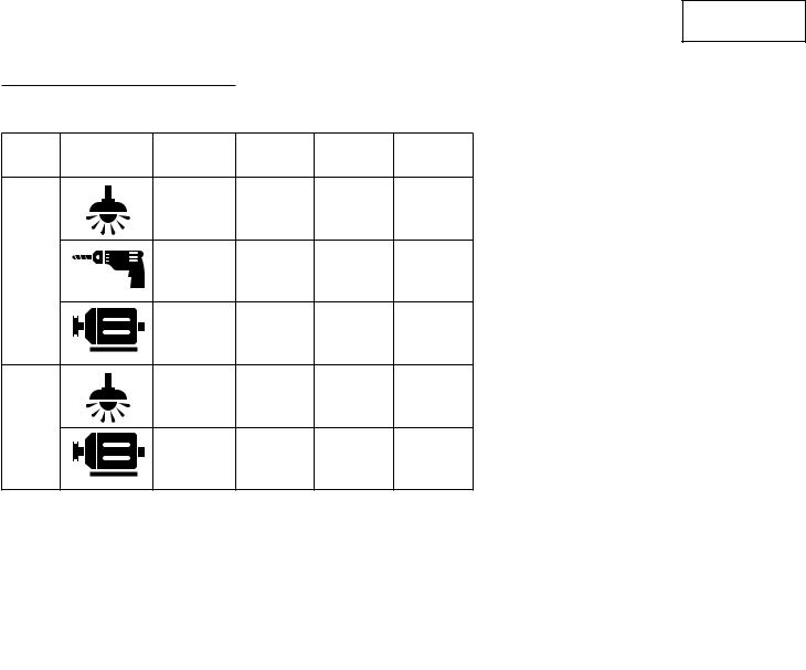
APPLICATION RANGE
Phase |
Apparatus |
Power |
E40(3P) |
E50(3P) |
E57(3P) |
factor |
E57(S3P) |
||||
|
|
1.0 |
~1,100W |
~1,400W |
~1,700W |
1 |
|
0.8~0.95 |
~880W |
~1,120W |
~1,360W |
|
|
0.4~0.75 |
~370W |
~480W |
~580W |
|
|
(Efficiency |
|||
|
|
0.85) |
|
|
|
|
|
1.0 |
~2,600W |
~3,400W |
~4,100W |
3 |
|
0.8 |
|
|
|
|
|
~1,560W |
~2,040W |
~2,460W |
|
|
|
(Efficiency |
|||
|
|
0.8) |
|
|
|
NOTE: “ ~ ” means below.
Application wattage indicates when each apparatus is used by itself.
CAUTION: Be sure the total load is with-in generator rated output for each phase, otherwise generator damage will occur.
Do not use 1-phase and 3-phase at the same time, or the electric apparatus may be damaged.
7

English
SPECIFICATIONS
ALTERNATOR
|
|
|
|
|
|
|
|
|||
Model |
E40(3P) |
E50(3P) |
E57(3P) |
|||||||
E57(S3P) |
||||||||||
|
|
|
|
|
|
|
||||
AC Output |
|
|
|
|
|
|
|
|
|
|
Phase (~) |
1 |
|
3 |
1 |
|
3 |
1 |
|
3 |
|
Cont. Rated Active Power (kw) |
1.1 |
|
2.6 |
1.4 |
|
3.4 |
1.7 |
|
4.1 |
|
Rated Power Factor |
1.0 |
|
0.8 |
1.0 |
|
0.8 |
1.0 |
|
0.8 |
|
Rated Frequency (Hz) |
|
|
|
|
50 |
|
|
|
||
Rated Voltage (V) |
230 |
|
400 |
230 |
|
400 |
230 |
|
400 |
|
Rated Current (A) |
|
4.8 |
|
6.1 |
|
7.4 |
||||
Safety Device |
|
|
|
N.F.B. |
|
|
|
|||
ENGINE
|
|
|
|
|
Model |
E40(3P) |
E50(3P) |
|
E57(3P) |
|
E57(S3P) |
|||
|
|
|
|
|
Name |
GM301P |
GM401P |
||
Type |
Air-cooled, 4 cycle, OHV, Gasoline |
|||
Displacement (cm3) |
296 |
391 |
|
|
Maximum Output (kw) |
7.4 |
9.6 |
|
|
Fuel |
Regular Automobile Gasoline |
|||
Fuel Tank Capacity (L) |
|
18.0 |
|
|
Operation Hours (h) |
9.5 |
8.0 |
|
7.0 |
Lubricating Oil |
Engine Oil SE Class or Higher |
|||
Lubricating Oil Capacity (L) |
|
1.0 |
|
|
Spark Plug |
|
BPR5ES (NGK) |
|
|
Noise Level (LWA) |
98 |
99 |
|
|
DIMENSIONS
Model |
E40(3P) |
E50(3P) |
E57(3P) |
E57(S3P) |
Length (mm) |
628 |
|
685 |
|
Width (mm) |
535 |
|
540 |
|
Height (mm) |
495 |
|
500 |
|
Dry Weight (kg) |
89 |
98 |
101 |
106 |
8
 Loading...