


PSS27SGMCBS
GE PSS27SGMCBS, PSS27SGMBBS, PSS27SGMABS, PSS25MCNAWW, PSS25MCNACC Owner’s Manual
...
www.GEAppliance&com
Safety h_ormation
Adapter Plugs ................... 4
Connect Electricity ............... 4
Extension Cords ................. 3
l'roper Disposal ................. 3
Safety l'recautions ............... 2
Models21,23,25,27, and29
o_
Operating Instructions
Additional Features ............. 11
Automatic Icemaker ............ 13
Care and Cleaning ........... 15, 16
CustomCool TM ................ 6, 7
Ice and Water Dispenser ...... 14, 15
Refiigerator Doors .............. 11
Replacing the IJghtbulbs ........ 17
Shelves and Bins .............. 9, 10
Storage Drawers ................ 12
Temperature Conwols ........... 5
Water and FreshSaver TM Filters .... 8
Installation InstJTtetions
Preparing to Install
the Refiigerator ............. 24, 25
Removing and Replacing Doors . .23
Trim Kits and Panels ......... 18-22
Water IJne Installation ....... 26-30
Troubleshooting Tips
Before You Call For Service ...32-34
Normal Operating Sounds ....... 311
Profile C6te _ C6te
R6frig6rateurs
La section frangaise commence a la page 42
Profile Lado a Lado
Refrigeradores
La secci6n en espa#ol empieza en la paoina 78
Consumer Support
Consumer Support ...... Back (;over
Performance Data Sheet ......... 37
Product Registration ......... 39, 40
State of California Water
Treatment Device Certificate ..... 38
Warranty (Canadian) ........... 35
Warranty (U.S.) ................ 36
Writethemodelandserial numbershere:
Model #
Serial #
Find these numbers on a label inside
the refligerator (ompartment at the
top on the right side.
200D2600PO05 49-60133 03-01JR
IMPORTANTSAFETYINFORMATION.
READALLINSTRUCTIONSBEFOREUSING.
A WARNING!
Use this appliance only for its intended purpose as described in this Owner's Manual
SAFETYPRECAUTIONS
When using electrical appliances, basic safety precaufions should be followed, including the following:
This refrigerator must be properly installed
and lo(ated in a((ordan(e xfith tile Installation
Instructions beti)re it is used,
_>Do not allow children to climb, stand or hang
on the shelves in tlle refiigerator. They could
damage tlle retiigerator and seriously injure
thelilselves.
Do not touch the cold surihces in tile fieezer
( omparmmnt when hands are damp or wet. Skin
may stick to these extremely cold sudilces.
Do not store or use gasoline or other flamnlable
vapors and liquids in the xd(inity of this or any
other appliance,
_,':_In retiigerators with automatic icemakers,
avoid contact with tile m()ving parts of the
ejector mechanism, or with the heating element
that releases the (ubes. Do not place fingers or
hands on the automatic icemaking mechanism
while the retiigevator is plugged in.
Keet) fingers out of tile "pinch point" areas;
clemances between tile doors and between
tile doors and (abinet are necessarily small.
Be carethl {losing doors when children are
in tile area.
_,'_Unplug the refligerau)r betore cleaning and
making repairs.
NOTE:Westronglyrecommendthatanyservicingbe
performedbyaquafifiedindividual
_'_'Setting either or both conuols to 0 (off) does not
remove power to tile light circuit.
_>1)o not refleeze fiozen foods which have
thawed completely.
::Always(leantheCustomCool Tray after thawing
food.
TM _,
2
vvvvw.GEAppliances.com
DANGER!RISKOFCHILDENTRAPMENT
PROPERDISPOSALOFTHEREFRIGERATOR
(hild enuapmem and suttbcafion are not problems
of the past.Junked or abandoned reiiigerators are
still dangerous...even if tile) _dll sit tot "just a tew
days." If you are getting rid of your old refrigerator,
please ti)lh)w the instructions below to help prevent
acdden/s.
Before YouThrowAway YourOld Refrigerator
or Freezer:
i_YTake offthe doors.
>_I,eave the shelves in place so that children may
not easily dimb inside.
CFCOisposal
Your old refrigerator may have a cooling system
that used (FCs ((hlorofluoro(arbons). (F(s are
believed to harm suatospheri_ ozone.
If you me throwing away your old refrigerator, make
sure the CFC refiigerant is rem{)ved fin proper
disposal by a qualified servicer. If you intentionally
release this CFC retiigerant you can be subject to
fines and imprisonment under pr_Msions of
environmental legislation.
USEOFEXTENSIONCORDS
Because ofpotential safety hazards under certain conditions, we strongly recommend against the use
of an extension cord.
However, if you must use an extension cord, it is absolutely necessa U that it be a UI Aisted (in the United
States) or a CSA-listed (in (_anada), 3-x_ate gtoundmg type apphan_ e extensum _ot d haxdng a grounding
type plug and outlet and that the ele_ uk al rating of the _ord be 15 amperes (minimum) and 120 vohs.

IMPORTANTSAFETYINFORMATION.
READALLINSTRUCTIONSBEFOREUSING.
A WARNING!
HOWTOCONNECTELECTRICITY
Do not, under any circumstances, cut or remove the third (ground) prong from the power cord. For
personal safety this appliance must be properly grounded.
The pc)wer cord of this appliance is equipped xfith
a 3-prong (grounding) plug which mates _dth a
standard 3-prong (grounding) wall outlet to
minimize the possibility of elecuic shock hazard
fiom this appliance.
Have the wall outlet and circuit checked by a
qualified ele(trician to make sure the outlet is
properly grounded.
If tile oudet is a standard 2-prong oudet, it isyour
personal responsibility and obligation to have it
repla(ed _dth a properly grounded 3-prong wall
outlet.
The refrigerator shouM always be plugged into its
own indMdual electrical outlet which has a vohage
rating that matches tlle rating plate.
This provides the best performance and also
prevents overh)ading house wiring cir(uits whidl
could cause a tire hazard flom overheated wires.
Never unplug your reffigervUor by pulling on tlle
power (ord. Ahvays grip plug firmly and pull suaight
out fiom the outlet.
Repair or replace immediately all power cords that
have become fiayed or otherwise dmnaged. Do not
use a cord that shows cracks or abrasion dmnage
along its length or at either end.
When moving tile refrigerator away flom the
wall, be (mefhl not to roll over or damage the
power cord.
USEOFADAPTERPLUGS(Ad_pte_plug_notpe_mittedinC_,_d_)
Because ofpotential safety hazards under certain conditions, we strongly recommend against
the use of an adapter plug.
H{rwever, if you must use an adapter, where local
codes permit, a temporaryconnectionmay be made
to a properly gn nmded 2-prong wzdl outlet by use
ofa UI Aisted adapter available at most local
hardware stores.
The larger slot in the adapter must be aligned with
the larger sh)t in the wall outlet to proxdde proper
polarity in the cr)nnection of the power cor'd.
When disconnecting the power cord fl'om the
a&lpter, always hold the adapter in place with one
hand while pulling the power cord plug with the
other hand. If this is not done, the adapter gr(rund
terminal is very likely to break with repeamd use.
If the adapter ground terminal breaks, DONOT
USEthe refrigerator until a proper ground has
been established.
Attaching the adapter ground terminal to a waft outlet
cover screw does not ground the appliance unless the
cover screw is meta/, and not lesu/ated, and the waft
outlet is grounded through the house wiring. Youshou/d
have the circuit checkedby a qualified electric&n to make
sure the outlet is proper/y grounde_
READANDFOLLOWTHISSAFETYINFORMATIONCAREFULLY.
SAVETHESEINSTRUCTIONS
4
Aboutthe temperaturecontrols, vvww.GEAppliances.com
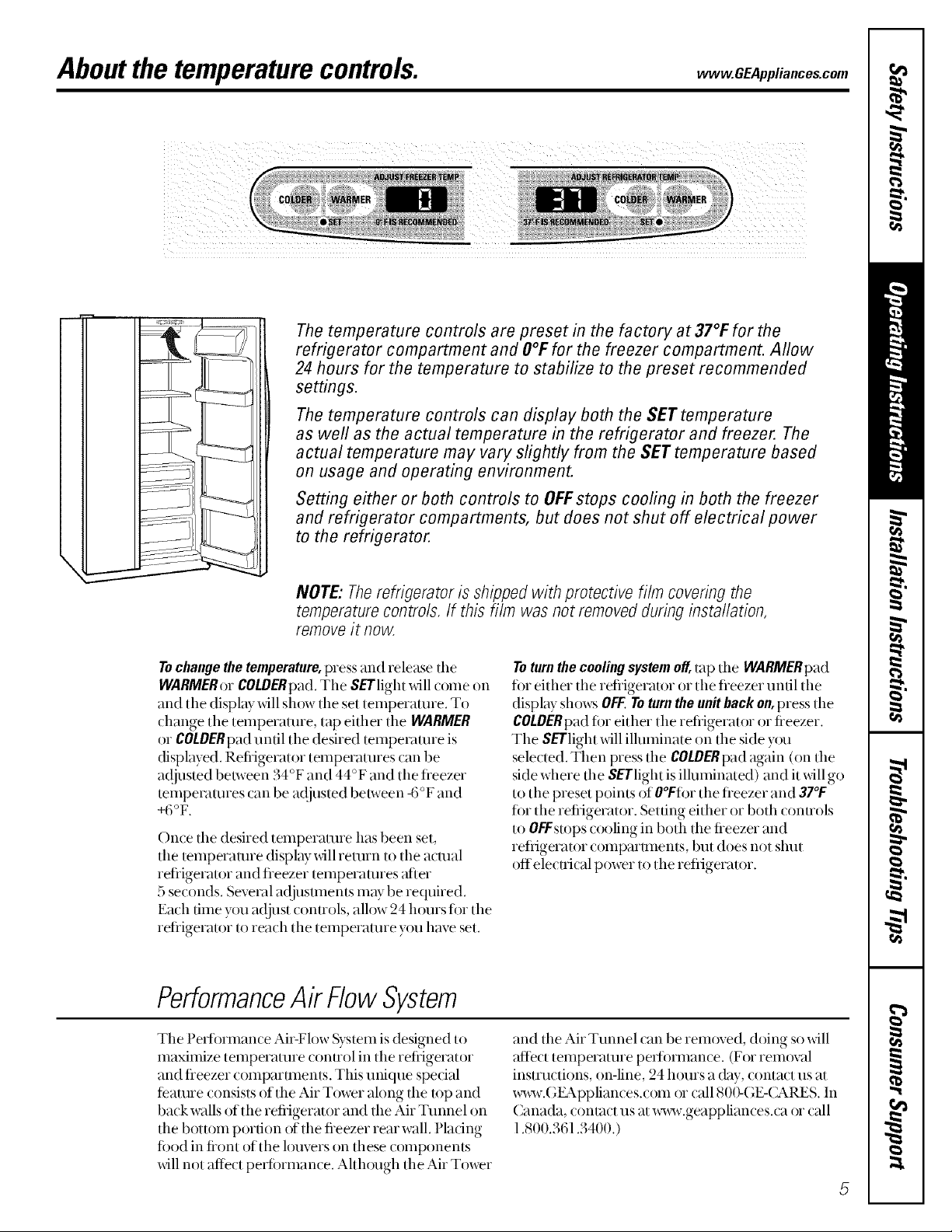
The temperature controls are preset in the factory at 37°1:for the
refrigerator compartment and O°Ffor the freezer compartment. Allow
24 hours for the temperature to stabilize to the preset recommended
settings.
The temperature controls can display both the SET temperature
as well as the actual temperature in the refrigerator and freezer. The
actual temperature may vary slightly from the SET temperature based
on usage and operating environment.
Setting either or both controls to OFFstops cooling in both the freezer
and refrigerator compartments, but does not shut off electrical power
to the refrigerator.
I
I
NOTE: Therefrigerator is shipped with protective film covering the
temperaturecontre/s, if this fi/m was not removedduring installation,
removeit now.
Tochangethetemperature,press and release the
WARMERorCOLDERpad.The SETlight _dll come on
and the display _fillsh_)wtile set temperature. To
change tile temperature, tap either the WARMER
or COLDERpaduntil the desired tempevaune is
displayed. Refiigerator temperaUnes can be
a(!justed belween 34°F and 44°F and tile tieezer
tempevaunes can be a(!justed be/ween -6°F and
+6°F.
Once tile desired temperature has been set,
the temperature displ Wwill return to the actual
retiigerator and fleezer temperatures aher
5 seconds. Several a(!jusunen/s may be required.
Each time you a({just conuols, allow 24 houxs tox tile
retiigerator U)reach the temperature you have set.
Toturn the cooling system off,tap the WARMERpad
fin either the retiigerator or tile fieezer until tile
display shows OFF.Toturnthe un# back on, press tile
COLDERpadfin either the refiigerator or fieezer.
The SETlight will ilhmfinate on the side y{xu
selected. Then press the COLDERpad again (on the
side where the SETlight is ilhnninated) and it will go
to the preset poims of O°Fti)rthe fleezer and 37°1:
fin the refiigerator. Setting either or both conuols
to OFFstops cooling in both the fieezer and
refiigerator comparm_en/s, but does not shut
offelecuical power to the refiigerator.
PerformanceAir FlowSystem
Tile Pedi)rmance Air-Flow System is designed to
maximize temperature conuol in the refiigerator
and fleezer companmen/s. This unique spedal
feature consists of the Air Tower along tile mp and
back w_dlsof the refiigerator and the Air Tunnel on
the bottom portion of the fieezer rear wall. Pladng
fi)od in fiont of the louvers on these components
will not affect pedinmance. Alth{xugh the Air Tower
and the Air Tunnel can be rem{)ved, doing so will
affect temperaUne pevlinmance. (Fox removed
instructions, on-line, 24 hours a day, contact us at
x_w.GEAppliances.com or call 800-GE-CARES. In
Canada, contact us at x_v.geappliances.ca or call
1.800.361.3400. )
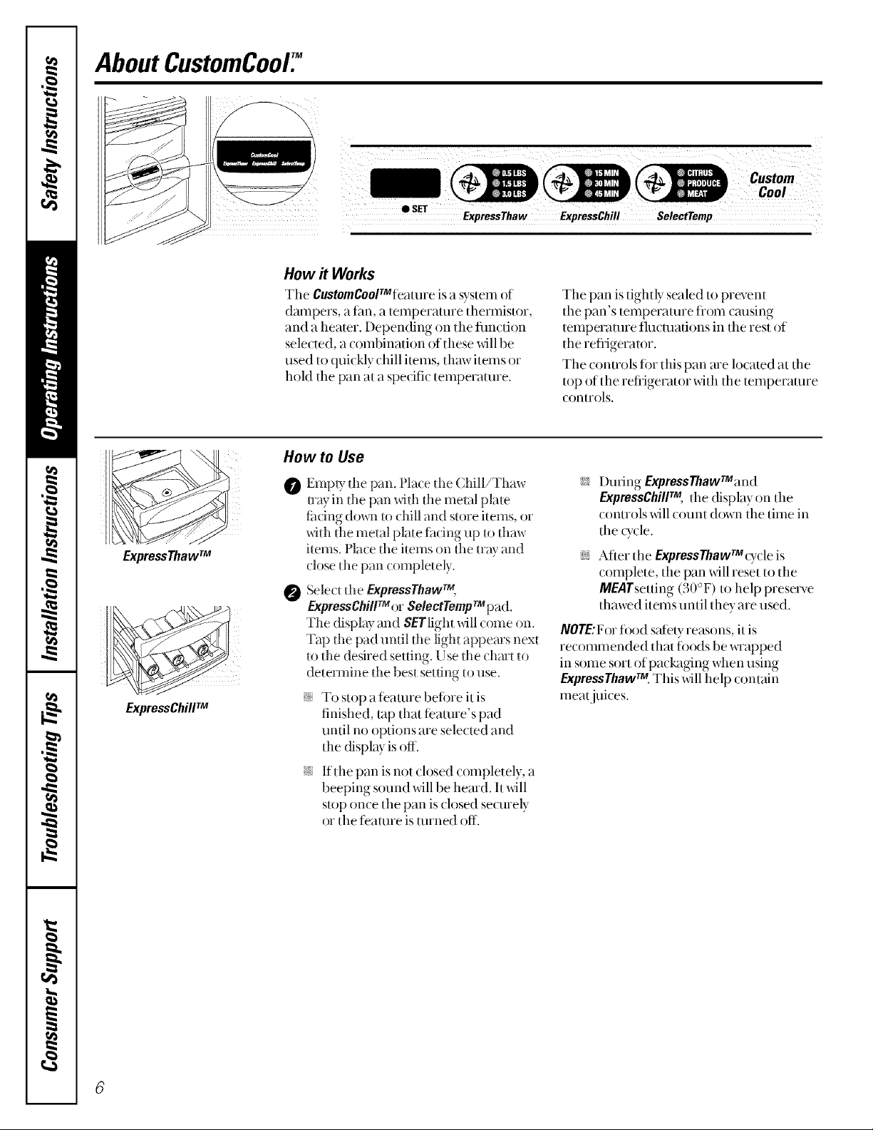
AboutCustomCool7
ExpressThawTM
ExpressChillTM
• SET
ExpressThaw ExpressChill SelectTemp
How it Works
Tile CustomCoolTMteature is a system oJ
dampers, a tim, a temperature thermistor,
and a hearer. Depending on the flmction
selected, a combination of these _dll be
used to quickly chill items, thaw items or
hoM the pan at a specific temperature.
How to Use
Empty tile pan. Place dm ( hill/Thaw
0
uay in tile pan _tll tim metal plate
fiJ(ing down to (hill and store items, or
_ith the metal plate tix(:ing up to thaw
items. Place file hems on the u:ay and
close d_e pan completely.
Select tlle ExpmssThaw TM,
ExpressChill TM or SelectTemp TMpad.
The display and SETlight _dll (ome on.
Tap the pad until the light appears next
to the desired setting. Use tlle chmt to
determine the best setting to use.
i;y To stop a teamre befine it is
finished, tap that teamre's pad
until no options are selected and
the cfisplay is off.
The pan is tightly sealed to prevent
tile pan's temperature flom cruising
temperature fluctuations in the rest of
the refiigeramr.
The conuols fi)r this pan are located at the
top of the refiigerator with the temperature
controls.
i_[?During ExpressThawrMand
ExpressChillTM, the (fisplay on the
(onuols will (ount down tlle time in
the o_cle.
i_YAfter the ExpressThawrM(ydeis
complete, tile pan will reset to tile
MEATsetting (30 °F) to help presevve
thawed items until they are used.
NOTE:Forfi)od salely reasons, it is
recommended that fi)ods be x_Tapped
in some sort of pacl%ging when using
expressThaw .This will help contain
ineatjuices.
i_Y If the pan is not ch)sed completely, a
beeping sound _dll be hemd. It will
stop on(e the pan is (losed se(urely
or the feature is turned off.
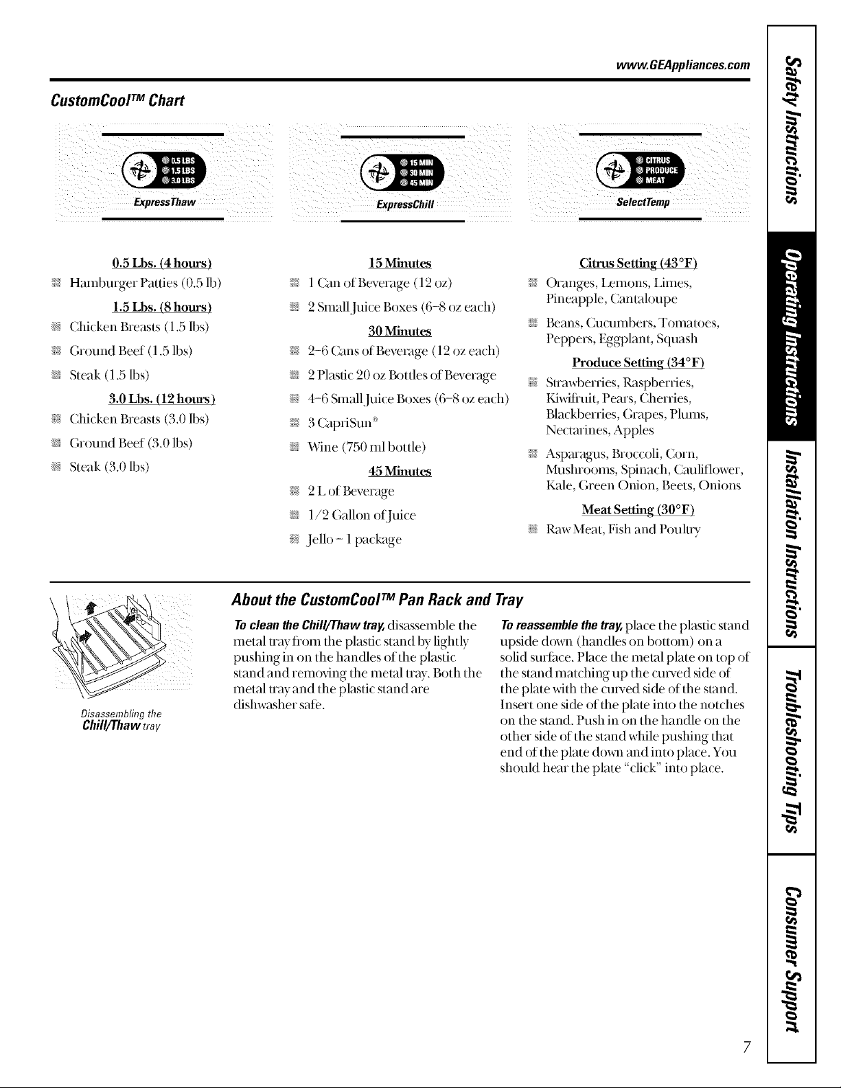
CustomCoolTM Chart
vvvvw.GEAppliances.com
0.5 Lbs. (4 hours)
;i:; Hamburger Patties (0.5 lb)
1.5 Lbs. (8 hours)
i__ Chicken Breas/s (1.5 lbs)
i_: Ground Beef (1.5 lbs)
i__ Steak (1.5 lbs)
3.0 Lbs. (12 hours)
i_: (hicken Breasts (3.0 lbs)
i_: Ground Beef (3.0 lbs)
i_: Steak (3.0 lbs)
Disassembling the
Chill/Thaw tray
15 Minutes
i_: 1 Can of Beverage (12 oz) >_
i__ 2 Small Juice Boxes (6-8 oz each)
30 Minutes
i_: 2-6 Cans of Beverage (12 oz each)
i_: 2 Plastic 20 oz Bottles of Beverage >;
i_[__ 4-6 Small Juice Boxes (6-8 oz each)
i_: 3 CapriSun"
i_: Wine (750 ml bottle) >;
45 Minutes
i_: 2 I, of Beverage
i_: 1/2 Gallon ot[]uice
;i:_Jello- 1 paclctge
About the CtlstomCoolTM Pall Rack and Tray
Toclean_e Chill/Thawtray,disassemble the
metal uay flom tile plastic stand by lightly
pushing in on the handles of the plastic
stand and rem(Mng tile melal tray. Both tile
metal Uay and the plastic stand are
dishw_Mmr sate.
Toreassemblethetray,place tile plastic stand
upside down (handles on bottom) on a
solid surlime. Place the melal plate on lop of
the stand matching up the cmx-ed side of
the plate with the cmx-ed side of the stand.
Insert one side of the plate into the notches
on the stand. Push in on the handle on the
other side of the stand while pushing that
end of the plate dox_lland into place. You
should hear the plate "click" into place.
Citrus Setting (43°F)
Oianges, I,emons, Limes,
Pineapple, Cantahmpe
Beans, (lilt tllill)eis, Tomatoes,
Peppers, Eggplant, Squash
Produce Setting (34°F)
Suawberries, Raspberries,
Kiwiffuit, Pears, ( herries,
Blackberries, Grapes, Plums,
Nectarines, Apples
Asparagus, Broccoli, (orn,
Muslnooms, Spinach, ( auliflower,
Kale, (heen Onion, Beets, Onions
Meat Setting (30°F)
Raw Meat, Fish and Pouluy
7
Aboutthe water andFreshSaverTM filters.
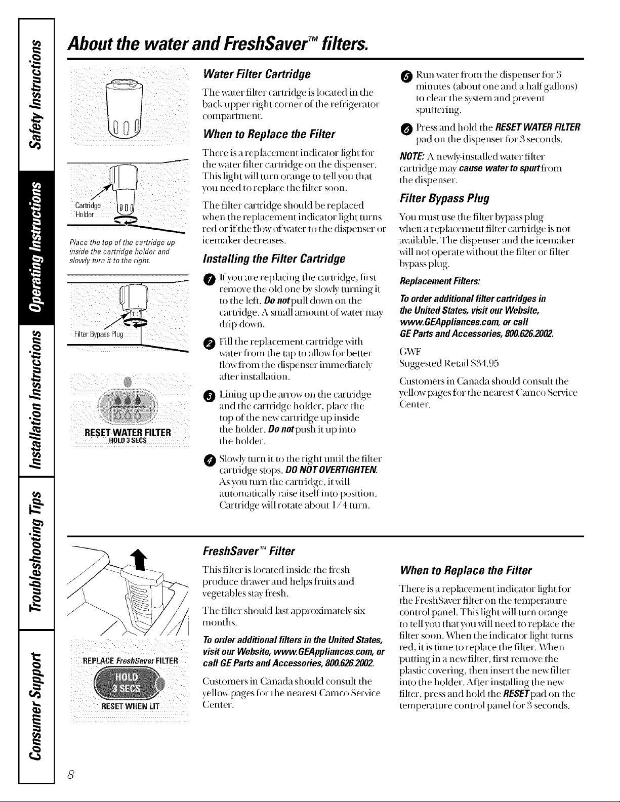
Place the top of the cartridge up
inside the cartridge holder and
slowly turn it to theright.
iii
RESETWATERFILTER
HOLD3 SECS
Water Filter Cartridge
Tile water fiher cartridge is located in tile
ba(k upper right (orner of tile refligerator
ct)tllparltllenL
When to Replace the Filter
There is a replacement indicator light fi)r
the water fiher caruidge on the dispenser.
This light will turn orange to tell y{tu that
you need to replace the fiher soon.
Tile fiher cmuidge should be replaced
when tile replacement indicator light turns
red or ittlle flow of water to the dispenser or
icemaker decreases.
Installing the Filter Cartridge
Ifyou are replacing tile caruidge, first
remove tile old one by sh)wly turning it
to the left. Do notpull down on the
caruidge. A stnall amount of water inay
(kip down.
Fill tile re -)lacemem caruid ,e xdth
water fiom the tap to alh)wfi)r better
flow flom the dispenser immediately
after installation.
Lining up the arrow on the caruidge
and the cmtridge holder, place the
top of the new cmtridge up inside
the holder. Do notD_sll it up into
the holder.
Run water flom the dispenser fi)r 3
minutes (about one and a half gallons)
to clem the system and prevent
sputtering.
Press and hold tile RESETWATERFILTER
pad on tile dispenser fi)r 3 seconds.
NOTE:A newly-installed water fiher
(aruidge may causewaterto spurtfiom
the dispenser.
Filter Bypass Plug
Y{)umust use the fiher bypass plug
when a replacement fiher caruidge is not
available. The dispenser and tile icemaker
will not operate without the fillet or fiher
bypass plug.
ReplacementFillers:
Toorderadditionalfillercartridgesin
theUnitedStates,vis#ourWebsite,
www.GEAppliances.com,orcall
GEPartsandAccessories,800.626.2002.
(A,\F
Suggested Retail $34.95
( ustomers in Canada should consuh the
yelh)w pages ti)r tile nearest Cameo Service
Center.
REPLACEFreshSaver FILTER
RESETWHEN LIT
Slowly turn it to the right until the fiher
(artridge stops. DONOTOVERTIGHTEN.
As you turn the (aruidge, it will
automatically raise itself into position.
Cartridge xdll rotate about 1/4 turn.
FreshSaver TM Filter
This fiher is h)cated inside tile tiesh
produce (hawer and helps fl_uitsand
vegetables staytiesh.
The fiher should last approximately six
intmths.
Toorder additional filters in the United States,
visit our Website, www.GEAppliances.com, or
call GE Parts andAccessories, 800.626.2002.
(_ustomers in Canada should consuh tile
yellow pages ti)r tile nearest (amco Service
Center.
When to Replace the Filter
There is a replacement indicator light tor
the FreshSaver fiher on the temperature
control panel. This light will turn orange
to tell you that you will need to replace the
fiher soon. When the indicator light turns
red, it is time to replace the fiher. When
putting in a new fiher, first rem_)ve tile
plastic covering, then insert the new fiher
into the holder. After installing the new
fiher, press and hold the RESETpadon the
temperature comrol panel fi_r3 seconds.
8
Aboutthe shelvesandbins. www.GEAppliances.com
Not all features are on all models.
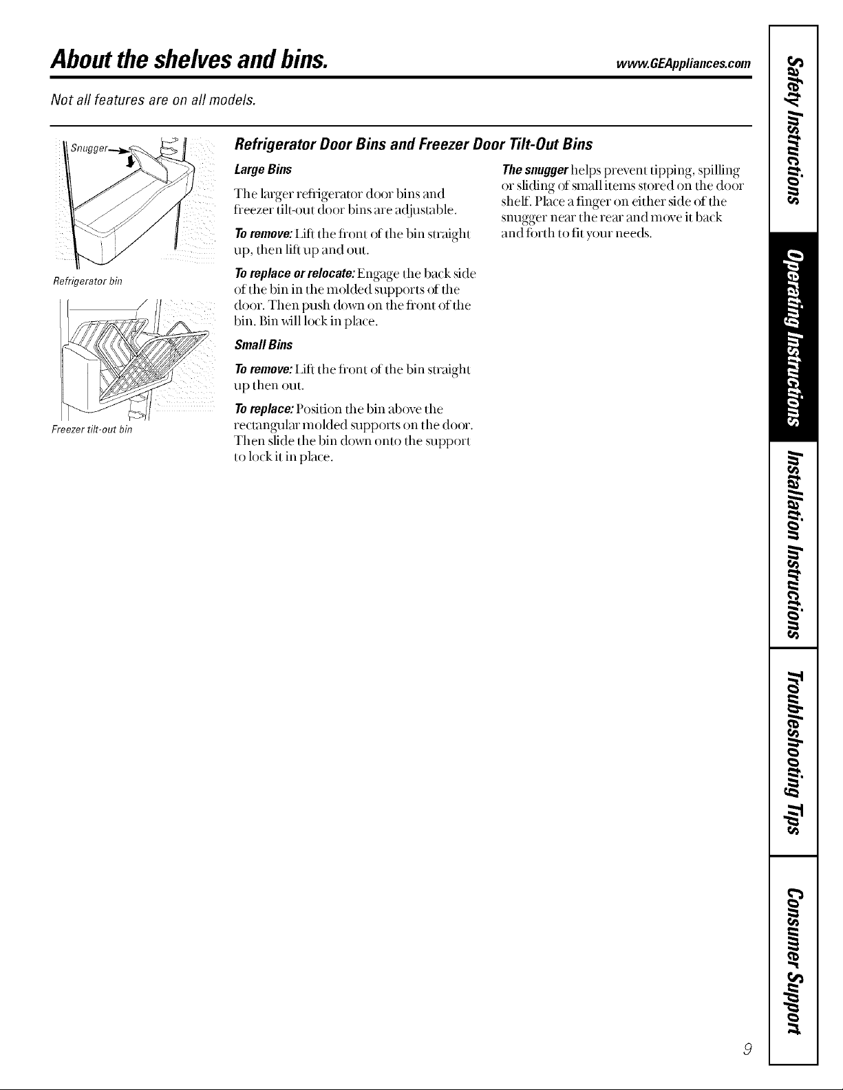
Refrigerator Door Bins and Freezer Door Tilt-Out Bins
LargeBins
The larger refiigerator door bins and
fleezer tih_)ut door bins are ac!justable.
Toremove: I,ifi tile front of tile bin straight
up, flmn lift up and out.
The snugger helps prevent tipping, spilling
or sliding of small items stored on the door
shell Place a finger on tither side of the
snugger nero the rein and m()ve it back
and ti_rth to fit your needs.
Refrigerator bin
Freezer tilt-out bin
Toreplace or relocate: Engage tile back side
of the bin in the molded supports of tile
door. Then push down on the flont of the
bin. Bin will lock in place.
SmallBms
Toremove: IJfi tile flont of tile bin straight
up then out.
Toreplace:Position the bin above tile
reclangulm rooMed supports on tile door.
Then slide the bin down onto the support
to lock it in place.
Abouttheshelvesandbins.(cont.)
Not all features are on all models.
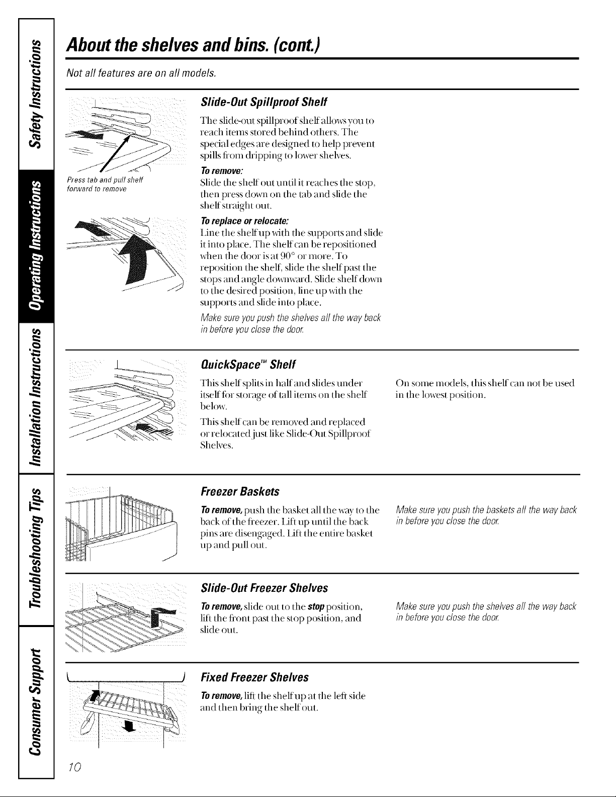
Slide-Out Spillproof Shelf
The slide-out spillproofshelfallows you to
read1 items stored behind others. The
spedal edges are designed to help prevent
spills fiom dripping to h)wer shelves.
Press tab and pull shelf
forward to remove
Toremove:
Slide the shelf out until it reaches tile stop,
then press down on the lab and slide the
shelf straight out.
Toreplaceorrelocate:
Ifine the shelf up with the supports and slide
it into place. The shelf can be repositioned
when tile door isat 90 o or iiloie. To
reposition the shell slide the shelf past the
stops and angle dox_llw,trd. Slide shelf down
to the (Dsired position, line up with the
supports and slide into place.
Makesureyoupushtheshelvesall thewayback
inbeforeyouclosethe door
OuickSpace TM Shelf
This shelf splits in half and slides under
itseffti)r storage of tall items on tile shelf
below.
This shelf can be removed and replaced
or relocated just like Slide-Out Spillproof
Shelves.
Freezer Baskets
Toremove, push the basket all the way to the
back of the fieezer. I,ifl up until the back
pins are disengaged. I,ifl the entire basket
up and pull out.
Slide-Out Freezer Shelves
Toremove,slide out to tile stopposition,
lift tile tiont past tile stop position, and
slide out.
On some models, this shelf can not be used
in the lowest p{)sifion.
Makesureyoupushthebasketsaft the wayback
in beforeyouclosethedoor
Makesureyoupushtheshelvesaft thewayback
in beforeyouclosethedoor
lO
) Fixed Freezer Shelves
Toremove,lift the shelf up at the left side
and then bring tile shelf out.
Abouttheadditionalfeatures, vvww.GEAppliances.com
Not all features are on all models.
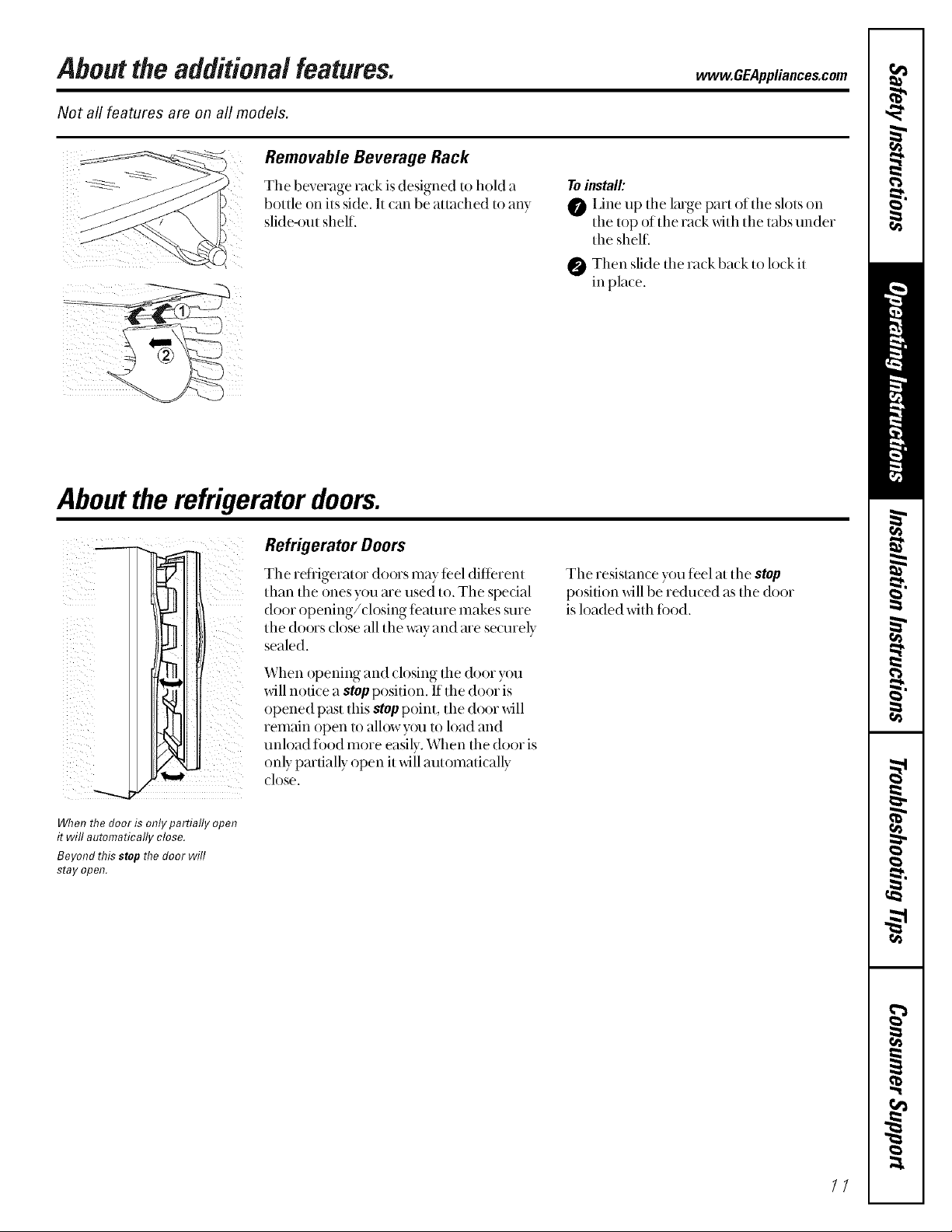
Removable Beverage Rack
The beverage rack is designed to heM a
bottle on its side, It (an be aua(hed to any
slide-out shelf.
i
Aboutthe refrigeratordoors.
Toinstall'.
O I,ine up tile kuge part of the slots on
tile top of the rack x_4thtile tabs under
the shel£
O Then slide tile rack back to lock it
in pla_ e.
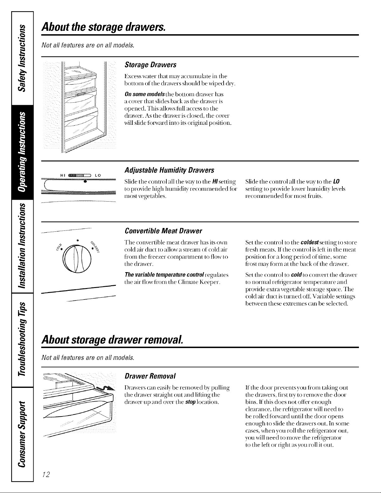
When the door is only partially open
it will automatically close.
Beyond this stop the door will
stay open.
Refrigerator Doors
The retiigerator doors may teel different
than the ones y{)u are used to. The special
door opening/closing teaune makes sure
the doors close all the way and me seolrely
sealed.
When opening and closing the door you
will notice a stop position. If the door is
opened past this stop point, tile door will
remain open to allow you to load and
unload ii)od more easily. When tile door is
only partially open it will automatically
close,
Tile resistance you feel at tile stop
position will be redu(ed as the door
is loaded x_4tllfood.
//
Aboutthe storagedrawers.
Not all features are on all models.
Storage Drawers
Excess water that may accumulate in tile
bottom of tile drawers sh(nfld be xdped (hT.
On some models the bottom (hvlwer has
a cover that slides back as the (h'awer is
opened. This all(tws filll access to the
!!_i_
drawer. As the (hmver is closed, the o tver
xdll slide fi nwmd into its original position.
HI _ LO
0
Adjustable Humidity Drawers
Slide tile conuol all the way to the HIsetting
to prox4de high humidity re(ommended fi)r
most vegetables.
Convertible Meat Drawer
o o
The convertible meat drawer has its own
cold air (hlct to allow a stremn of cold air
flom the fieezer compartment to flow to
the drawer.
Thevariable temperature control regulates
the air flowflom the Climate Keeper.
Aboutstoragedrawer removal
Slide tile conuol all tile way to tile LO
setting to provide lower humidity levels
recommended for most fi'uits.
Set the control to the coldeMsetting to store
fiesh meats. If the control is left in tile meat
position fi)r a hmg period of time, some
fiost may fi)rm at the back of the (hawer.
Set tile control tt) coldu) convert tile (kawer
to normal refrigerator temperature and
prox4de extra vegetable storage space. The
cold air duct is turned ()tt_Variable settings
between these extremes can be selected.
Not all features are on all models.
Drawer Removal
Drawers can easily be removed by pulling
the drawer straight out and lifting the
drawer up and over tile stop h)cation.
/2
If the (loot prevents y()u fiom taking Ollt
the drmvers, first uT to remove the door
bins. If this does not offer en(tugh
clearance, tile refligerator will need to
be rolled fi)rward until the door opens
enough to slide the (hawers out. In some
cases, when you roll the refligerator out,
you _dll need to m()ve the refligeramr
to the left or right as you roll it out.
Aboutthe automaticicemaker, vvww.GEAppliances.com
A newly-installed refrigerator may take 12to 24 hours to begin making ice.
Power
3witct
Greel-
PnwerLgm
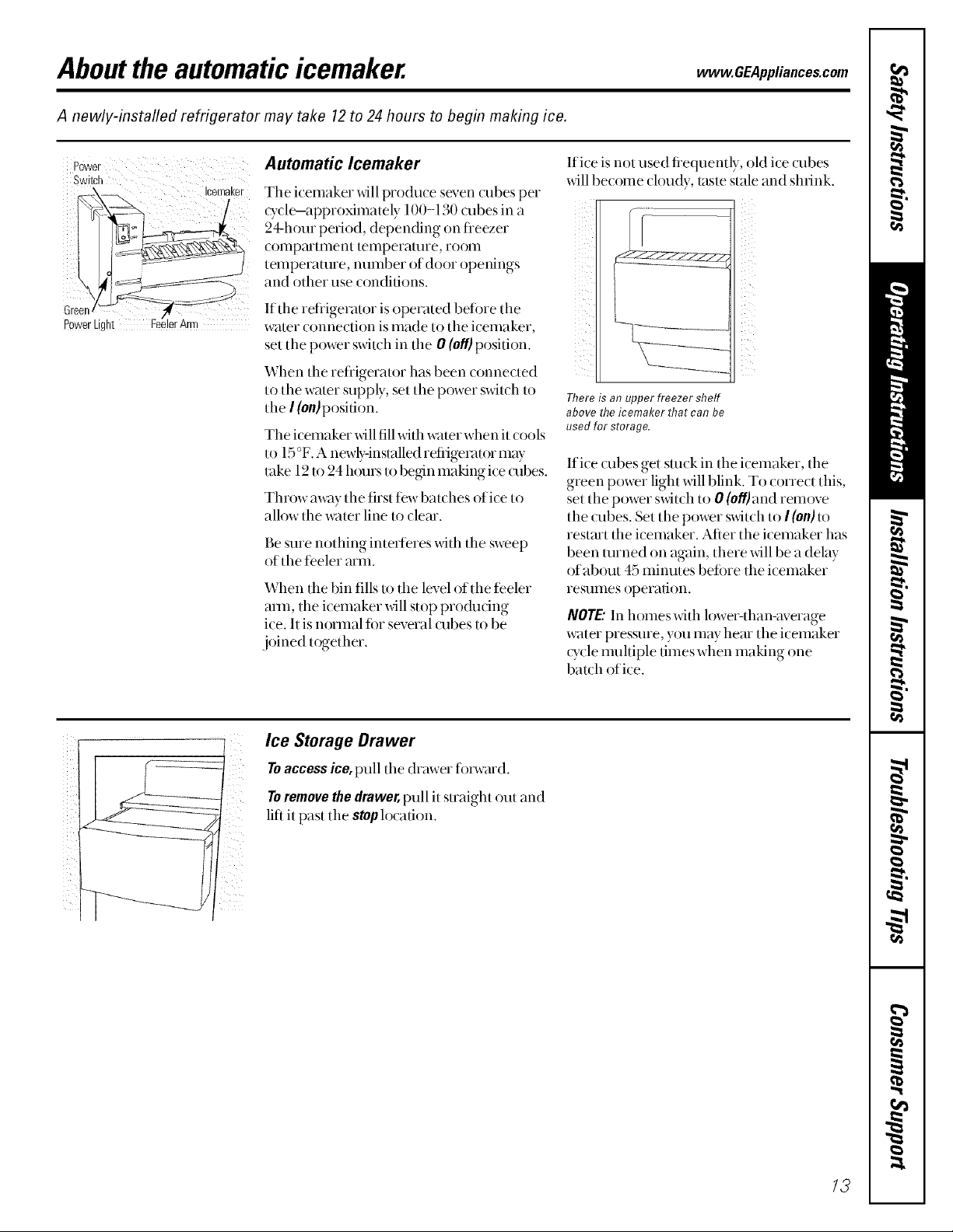
Automatic Icemaker lfi('e is II()[ lls#d fietltlently, old ice (llbes
xdll become cloudy, tasle stale mid slnink.
The icemaker _dll produ(e seven cubes per
(y( le--app_oximately l O0-130 cubesin a
24-hour period, depen(fing on tieezer
(omp_ummnt temperature, room
temperature, number of door openings
and other use conditions.
If the retiigerator is operated before the
water connection is made to tile i(emaker,
set the power switch in the 0 (eft) position.
When the refligerator has been connected
to the water supply, set the power switch to
the I(on) position.
The icemaker will fillwith water when it cools
to 15°F. A newb:-installed retiigemtor may
take 12to 24 hours tObegin making ice cubes.
Throw away the tirst tew batches of ice to
allow tile water line to clear.
Be sure nothing inter[eres _xdththe sweep
of the ti_eler arm.
When the bin tills to tile level of the teeler
am_, the icemaker _dll stop producing
ice. It is normal tot several cubes to be
joined t(Nether.
There is at?upper freezer shelf
above the icemaker that cat?be
used for storage.
If ice olbes get stuck in the icemaker, the
green power light will blink. To correct this,
set the power switch to 0 (oft)and remove
the cubes. Set tile power switch to I (on)to
restmt the icemaker. After the icemaker has
been turned on again, there will be a delay
of about 45 minutes beti)re the icemaker
resumes operation.
/VOTE."In homes with lower-than-average
water pressure, you may hear the i(emaker
Q_clemuhiple times when making one
batch of ice.
Ice Storage Drawer
Toaccessice,pull the drmver ti)mm(l.
Toremovethedrawer,pull it straight out and
lift it past the stoplocation.
/3

Aboutthe ice and water dispenser.
ToUsetheDispenser
SpillShelf
Select CUREDICE _, CRUSHEDICE
or WATER_.
Press the glass gendy against tile top of file
dispenser (radle.
Tile spill shelf is not self-draining. To
reduce water spotting, tile shelf and its grille
shouM be (leaned regularly.
If no water ls dispensed when the refrigerator ls
first lnstafled, there may be air in the water fine
system. Pressthe dispenser arm for at least two
minutes to remove trapped air from the water
fine and to fi// the water system. Toflush out
impurities in the water fine, throw away the first
six glassfuls of water
CAUTION:Neverput fingersorany other
objectsinto the ice crusherdischargeopening.
Lockingthe Dispenser
@ PresstheLOCKCONTROL
pad lot 3 seconds to lock
the dispenser and
conuol panel. To
LOCKCONTROL unhl(k, pressand
HOLD3SECS hoM tile pad again
fi)r 3 seconds.
Dispenser Light
This pad turns tile night
lightin tile dispenser on
and off. Tile light also
COIIles on when tile
LIGHT dispenser cradle is
pressed. Iftllis light
burns out, it shouM be
replaced with a 6 watt
12V inaxilnUln bulb.
QuickIce
@ When you need ice in a
huny, press this pad to
speedupice
production. This will
increase ice production
QUICKICE for tile ti)llo_dng 48
hours or until you
press tile pad again.
DoorAlarm
@ To set file alarm, press
.... this pad until tile
indicator light COlnes on.
This alarm will sound if
000R ALARM eifller door is open for
more than 3 minutes.
The light goes out and
the beeping stops when
you chlse tile door.
14
Important Facts About Your Dispenser
i_?Do not add ice flom Uays or bags to
tile storage drawer. It may not (rush or
dispense well.
>:Avoid overfilling glass with ice and use of
narrow glasses. Backed-up ice can jmn the
chute or cruise the door in the chute to
freeze shut, If ice is blocking the chute,
poke it through with a w()o(len spoon.
>: Beverages and fi)o(ls sll{)uM not be
quick-chilled in tile ice storage drawer.
Cans, bottles or fi)od packages in the
storage drawer may cause tile icemaker
or mlger to jmn.
i_?To keep dispensed ice fi'om missing
the glass, put the glass (h)se to, but not
tou(hing, the dispenser opening.
i_?Some crushed ice may be dispensed even
though you selected CUREDICE.This
happens occasionally when a tew (ubes
accidentally get directed to the crusher,
>_After crushed ice is dispensed, some
water may drip fiom tile (hute.
>_Sometimes a small m()und of snow will
fi)rm on tile door in tile ice chute. This
condition is nomlal and usually occurs
when you have (fispensed crushed ice
repeatedly. Tile snow xdll eventually
evaporate.
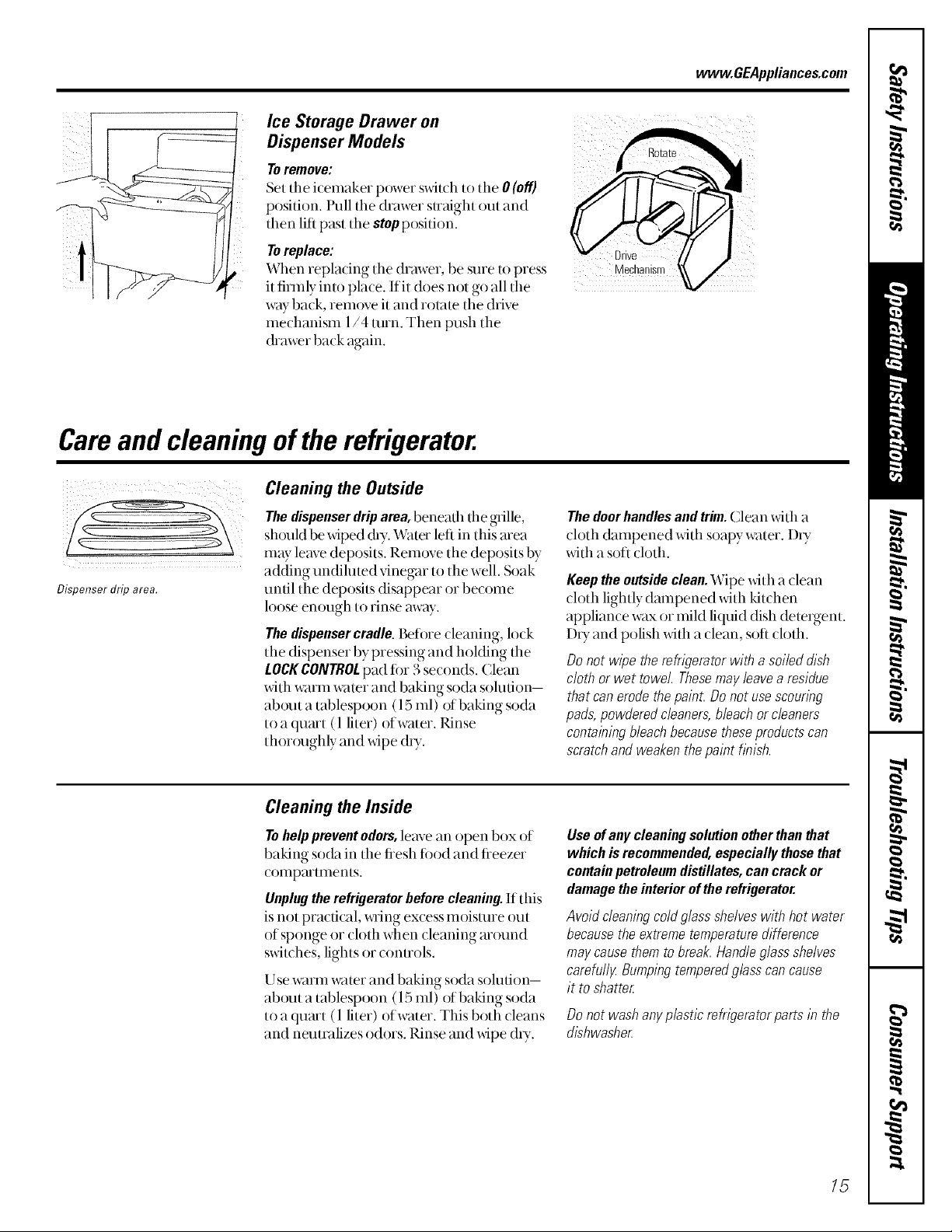
Ice Storage Drawer on
Dispenser Models
Toremove:
Set the icemaker power s_dtch to the 0 (off)
position, lhfll the drawer straight out and
then lift past the stop position.
Toreplace:
When replacing the drawer, be sure to press
it firmly into place. If it does not go all the
way back, rem_)ve it and rotam the drive
mechanism 1/4 turn. Then push the
&awer back again.
Careand cleaningof therefrigerator.
Cleaning the Outside
Thedispenser drip area, beneafll file grille,
sh{)uld be _dped (by. "v\_tterleft in this mea
m W leave deposits. Rem_)ve the deposits by
adding undiluted vinegar to the well. Soak
Dispenser drip area.
until the deposits disappear or become
loose enough to rinse away.
Thedispensercradle.Beti)re cleaning, lock
the dispenser by pressing and hoMing the
LOCKCONTROLpad fin 3 seconds. Clean
with warm water and baking soda solution-
about a tablespoon (15 ml) of baking soda
to a quart (1 liter) of water. Rinse
thor(n@fly and wipe (hy.
vvww.GEAppliances.com
Thedoorhandlesandtrim.Clean xdth a
(h)th dampened with soapy water. DU
xdth a soft ch)th.
Keep theoutsideclean.Wipe with a clean
cloth lightly dmnpened with kitchen
appliance wax or miM liquid dish detexgent.
DU and polish with a clean, soft cloth.
Donot wipe the refrlgeretorwith a soileddish
cloth orwet towel Thesemayleavea residue
that canerodethepaint.Donotusescounng
pads,powderedc/eanere,bleachorc/eanere
containingbleachbecausetheseproductscan
scratchand weakenthepainthbish.
Cleaning the Inside
Tohelp prevent odors,leave an open box of
baking soda in the tiesh ti)od and tieezer
(ompartments.
Unplugtherefrigeratorbeforecleaning.If this
is not practical, _ring excess moisture out
of sponge or cloth when deaning m{nmd
sxdwhes, lights or conuols.
Use warm water and baking soda solution-
about a tablespoon (15 ml) of baking soda
to a quart (1 liter) of water. This both deans
and neutralizes odors. Rinse and wipe dU.
Use of any cleaning solution other than that
which is recommended, especially those that
contain petroleum distillates, can crack or
damage the interior of the refrigerator.
Avoid cleaning cold glass shelves with hot water
because the extreme temperature difference
may cause them to break. Handle glass shelves
carefull_z Bumping tempered g/ass can cause
it to shatter
Donot washanyplasticrefrigeratorpartsin the
dishwasher
15
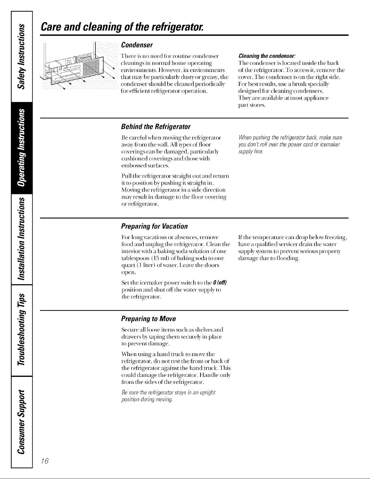
Careand cleaning of therefrigerator.
Condenser
There is no need for routine (ondenser
cleanings in nom_al home operating
' enxdronments. However, in enxdromnents
that may be particularly dusty or greasy, tile
.. " condenser should be cleaned periocficallv
" for efficient refrigerator operation.
Behind the Refrigerator
Be cmefifl when moving the refiigerator
away fi'om tile wall. All/ypes of floor
c_)verings can be damaged, parficulmly
(ushioned c()verings and those with
embossed surlimes.
Pull tile refiigerator straight out and return
it to position by pushing it suaight in.
M_)ving the refiigerator in a side direction
may result in dnmage/o tile floor c_)vefing
or refrigerator,
Preparing for Vacation
Cleaning the condenser:
Tile condenser is located inside the back
of the refligerator. To access it, rem{_ve the
cover. The condenser is on the fight side.
Fox best resuhs, use a brash specially
designed tot cleaning condensers.
They are m;filable at most appliance
part stores.
When pushing the refngerator back, make sure
you don't roll over the power cord or icemaker
supply hne.
For long vacations or absences, iem()ve
fi)od and unplug the refiigerator. Clean the
interior with a baking soda solution of one
tablespoon (15 ml) of baking soda to one
qum't (1 liter) of water. I,eave the doors
open.
Set tile icemaker power switch to the 0 (off]
position and shut off tile water supply to
the refrigerator.
Preparing to Move
Secure all loose items such as shelves and
drawers by taping them se(mely in place
to prevent damage.
When using a hand truck/o move the
retiigerator, do not rest tile flont or back of
the retiigerator against the hand track. This
could dmnage the refrigerator. Handle only
fiom the sides of the refligeramr.
Be sure the refrigerator stays in an upwht
position during moving.
If tile temperature can &op below fleezing,
have a qualified secvicer dr;fin the water
supply syslem to prevent seri_xusproperty
damage &_e to flooding.
16
Replacingthelightbulbs, vvww.GEAppliances.com
Setting the controls to OFFdoes not remove power to the light circuit.
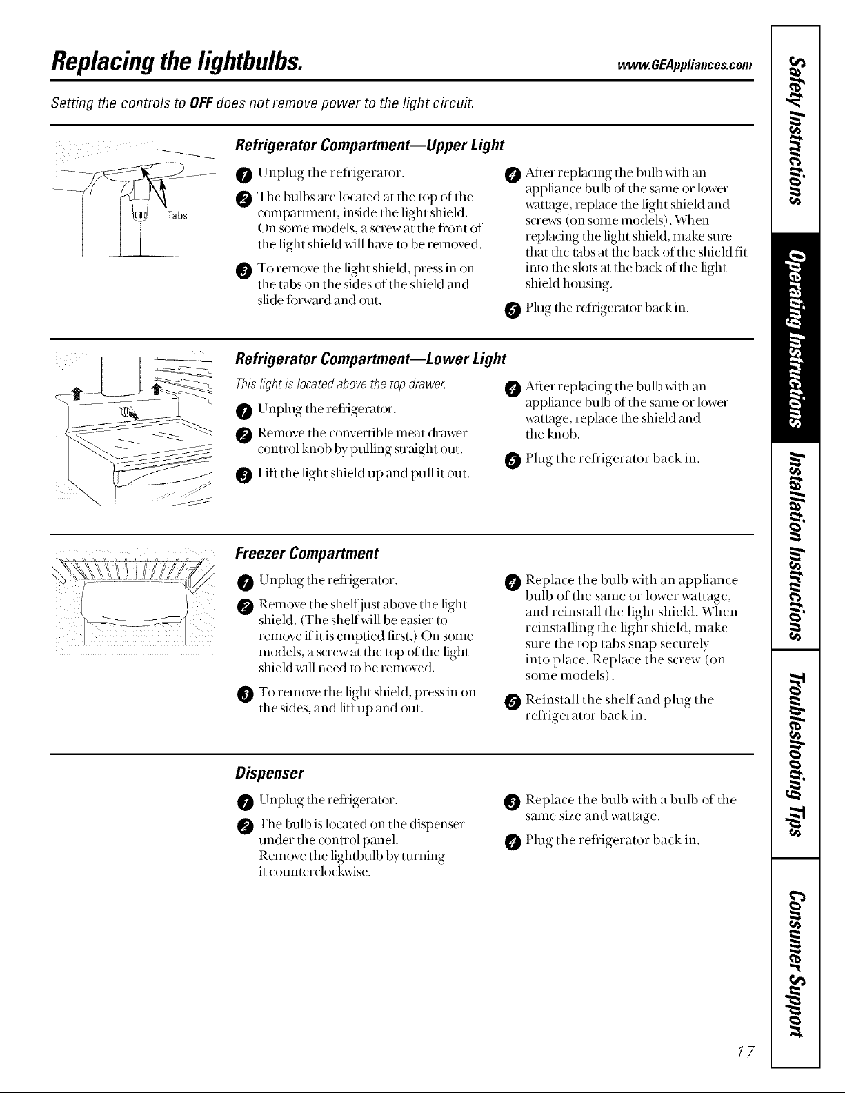
Refrigerator Compartment--Upper Light
After replacing tile bulb with an
0 Unplug tile refligerator.
The bulbs are located at the top of the
compartment, inside the light shieM.
On some models, a screw at the front of
the light shield xdll have m be rein{wed.
To remove tile light shieM, press in on
tile tabs on tile sides of the shieM and
slide fi)rward and out.
Refrigerator Compartment--Lower Light
0
appliance bulb of tile stone or lower
wattage, replace the light shield and
screws (Oilsome models). When
repladng the light shield, make sure
that the robs at the back of the shield fit
into the slots at the back of the light
shield housing.
Plug tile refligerator back in.
Thisfightislocatedabovethetopdrawec
Unplug tile refiigerator.
Remove the convertible meat &awer
control knob by pulling smtight out.
IJfl the light shield up and pull it out.
Freezer Compartment
Unplug tile refligerator.
0
Remove the sheltjust above the light
@
shieM. (The shelfxdll be easier to
remove flit is emptied first.) On some
models, a screw at tile top of tile light
shieM xdll need to be removed.
To remove tile light shield, press in on
tile sides, and lift up and out.
Dispenser
After replacing tile bulb x_4tllan
appliance bulb of tile same or lower
wattage, repla¢e tlle shield and
tile knob.
Plug tile refligerator back in.
Replace tile bulb with an appliance
@
bulb of tile same or lower wattage,
and reinstall the light shield. When
reinstalling the light shieM, make
sure the top tabs snap securely
into place. Replace the screw (on
some models).
Reinstall tile shelf and plug tile
refligerator back in.
Unplug tile refrigerator.
The bulb is located on the dispenser
under the control panel.
Rem_)ve tile lightbulb by unning
it o)untercl0ckwise.
Replace tile bulb with a bulb of tile
saIIle size and wattage.
Plug tile refligerator back in.
17
Trimkits anddecoratorpanels.
For CustomS&/eTM models
Read these instructions completely and carefully.
BeforeYouBegin
Some models are equipped with trim kits that aflow you to instafl door panels. You can order pre-cut
black, white, almond, bisque, or stainless steel decorator panels from GEParts and Accessories,
800.626.2002,or you can add wood panels to match your kitchen cabinets.
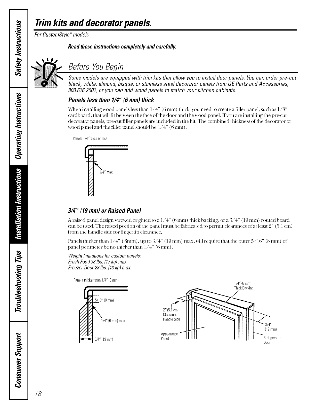
Panels less than 1/4" (6 mm) thick
When installing wood panels less than l/4" (6 ram) thi(k, you need to create a filler panel, su(h as 1/8"
cmdboard, that x_illfit belween the titce of the door and the w()od panel. If}_n_me installing the pre-cut
decorator panels, pre-cut filler panels me included in the kit. The combined thickness of the decorator or
wood panel and the filler panel should be 1/4" (6 ram).
Panels1/4"thickorless
1/4" max
3/4" (19 mm) or Raised Panel
A raised panel design screwed or glued to a 1/4" (6 ram) thick backing, or a 3/4" (19 ram) routed board
(an be used. The raised portion of the panel must be fabri(ated to permit (learan(es ()fat least 2" (5.1 (m)
fi'om the handle side for fingertip (learan(e.
Panels thicker than l/4" (6ram), up to 3/4" (l .)ram) max, wallrequne that the outer o/16 (8 ram) of
panel perimeter be no thi(ker than 1/4" (6 ram).
Weightlimitationsfor custompanels:
FreshFood38Ibs. (17kg) max.
FreezerDoor28Ihs.(13kg) max.
Panelsthickerthan1/4" (6mm)
2"(5.1 cm) II llll __---"...._",-_
1/4"(6mm)
ThickBacking
ClearanceII IIII _"
3/4"(19mm) pAP_ee_ra"ceqi111 • ,or
Door
18
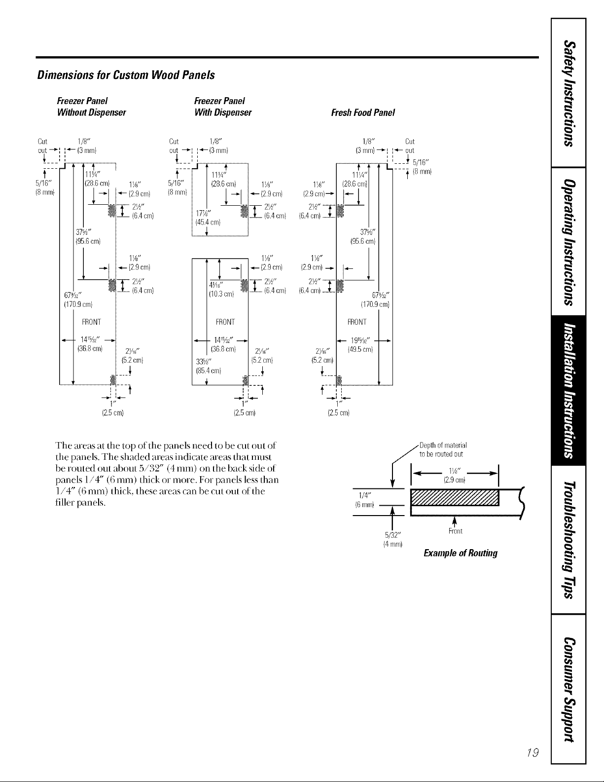
Dimensions for Custom Wood Panels
FreezerPanel
WithoutDispenser
Cut 1/8"
out-_I I_- (3mm)
i i
t
5/16"
(8mm}
37%"
(95.6cm)
67%Z
(170.9cm)
FRONT
_. 141%2" _
(36.8cm) 2¼s"
Out 1/8"
out -_I I_'-(3 mm)
_, ,,
cm) 1Y?"
7_- 21/2"
iX_I -I290m>
-"I 4- (2.9cm)
(6.4cm)
11A,,
(6.4cm)
(5.2cm)
5/_6 [ 111A"
.... -I I #
< mm>/
FreezerPanel
With Dispenser
i i
" (28.6cm)
_- {2.9cm)
177_" l_
(45.4ore)
T -'29cm>
,, _ T- 2½"
(10.3cm) -- Jh (6.4cm)
1(36.8 cm) 2>_"
33%" (5.2cm)
(85.4cm) _,
Z2_"
16.4cm)
11_"
11_"
(2.9cm)--_
2W' _
(6.4cm)
1½"
(2.9cm) --i-
2W' _
(6.4cm)
2Hs"
(5.2cm)
FreshFoodPanel
1/8" Cut
(3mm)--_I I"4- out
11'_1/4,,l /---'_ {8 nlm}
(28.6cm)/
#x/
° /
37%"
(95.6cm)
#1
(170.9cm)
FRONT
-_-- 19%Z'----_
(49.5cm)
!,
,, _,
' '---- 5/16'*
67%2'*
I, t
1"
(2.5cm}
The areas at the top of the panels need to be Qlt out of
the panels. The shaded areas indicate areas that nmst
be routed out about 5/32" (4 ram) on the back side of
panels 1/4" (6 ram) thick or more. For panels less than
1/4" (6 ram) thick, these meas can be uut out of the
filler panels.
i t
1"
(2.5cm)
f ,',
(2.5cm)
i_1 Depthofmaterial
tobe routedout
i I (2.9cm)
114"
(6ram)T _<
5/32"
(4mm)
Front
ExampleofRouting
$
19

Insertingthe doorpanels.
Read these instructions completely and carefully.
0 Loosenthe TopTrim onthe Freezer and FreshFoodDoors.
Using a T-20 Torx driver, loosen the two screws
attaOling tile Top Trim about l/4" (6 ram).
Insert the Freezer Panel and FreshFood Panel
O
I,ifl tile Top Trim up l/4" (6 ram) and careflllly
push the fieezer panel in until it slides into the slot
behind the door handle. Push tile filler panel
(required with some door panels) in behind the
decorator panel. Repeat for flesh food panel.
Insert the Bottom Panel.
Cmefiflly push the panel in until it slides into the
slot behind the door handle, l'ush the fillet panel
(required with some door panels) in behind the
decorator panel.
If your model has a dispenser and/or a
Refleshment Center, this step only applies
to the top panels.
Hand tighten the two screws on the Top Trim.
Cut-Out
SideTrim
20
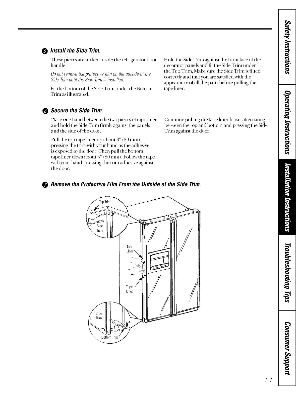
0 Install the Side Trim.
These pieces me rocked inside the retiigerator door
handle.
Donot removetheprotectivefiim on theoutsideof the
SideTrimuntil theSideTrimisinstallec!
Fit tile bottom of the Side Trim under the Bottom
Trim as illustrated.
Hold the Side Trim against tile fiont tace of the
decorator panels and fit the Side Trim under
the Top Trim. Make sure the Side Trim is fitmd
correctly and that you me satisfied with the
appearance of all the parts betore pulling the
tape liner.
Secure the Side Trim.
Place one hand be/ween the/wo pieces of tape liner
and hold the Side Trim firefly against the panels
and the side of the door.
Pull tile top tape liner up about 3" (80 ram),
pressing the trim with y{)ur hand as the adhesive
is exposed to the door. Then pull the bottom
tape liner down about 3" (80 ram). Follow the/ape
with y{mr hand, pressing the trim adhesive against
the door.
Condnue pulling the tape liner loose, alternating
belween the top and bottom and pressing the Side
Trim against the door.
Remove the Protective Film Fromthe Outside of the Side Trim.
21
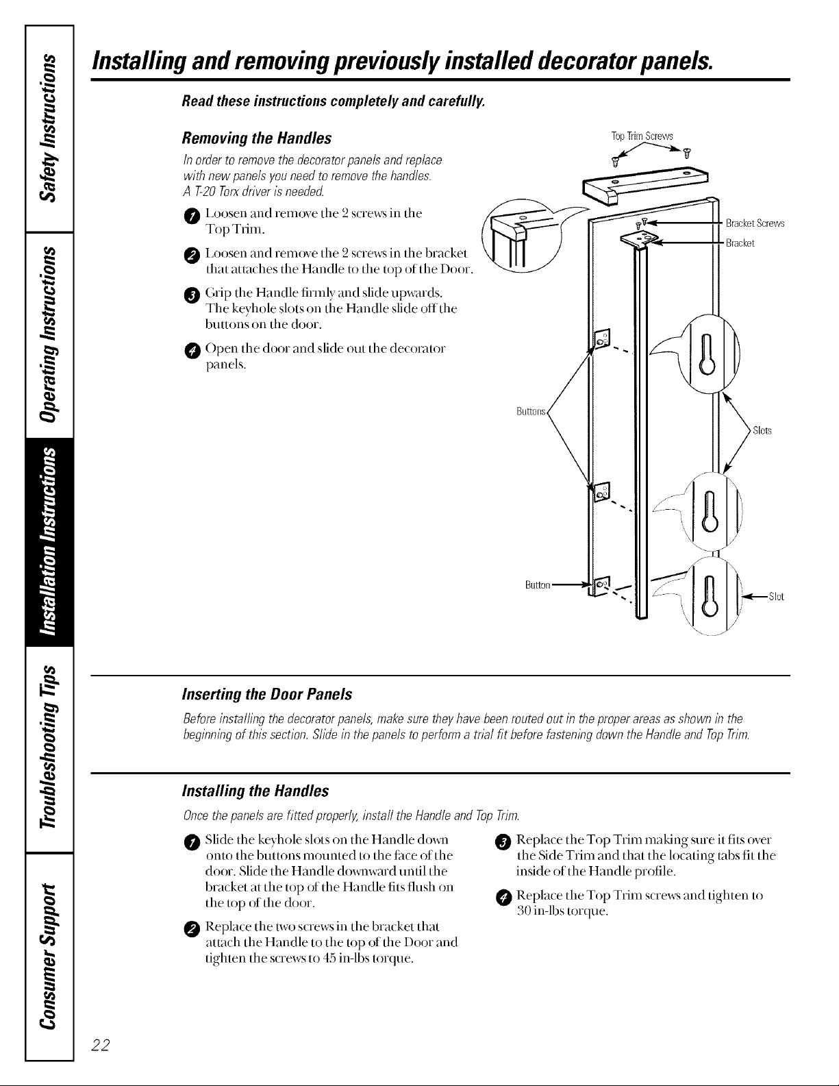
Installingand removingpreviouslyinstalled decoratorpanels.
Read these instructions completely and carefully.
Removing the Handles
In order to remove the decorator panels and replace
with new panels you need to remove the handles.
A T-20 Torxdriver is neede_
O I,oosen and remove the 2 screws in the
Top Trim,
I,oosen and remove tile 2 screws in the bracket
that auaches the Handle to the top of the Door.
Grip the Handle firmly and slide upwards.
The keyhole slots on the Handle slide offthe
buttons on the door.
Open the door and slide out the decot_uor
panels.
TopTrimScrews
BracketScrews
Bracket
Bu_ons
>Slots
22
Inserting the Door Panels
Before installing the decorator panels, makesure theyhave been routed out in the proper areas as shown/n the
beginmng of this section. Slide in the panels to perform a toal fit before fastemng down the Handle and Top Trim.
Installing the Handles
Oncethe panels are htted pmperly, install the Handle and TopTrim.
Slide the keyhole slots on the Handle do_a_
0
onto the buuons mounted to the til(e of the
door. Slide the Handle downward until the
bracket at the top of the Handle fits flush on
the top of the door.
Replace the two screws in the bracket that
@
attach the Handle to the top of the Door and
tighten the s_rews to 45 in-lbs torque.
Replace the Top Trim making sure it tits over
the Side Trim and that the locating tabs fit the
inside of the Handle profile.
Replace the Top Trim screws and tighten to
30 in-lbs torque.
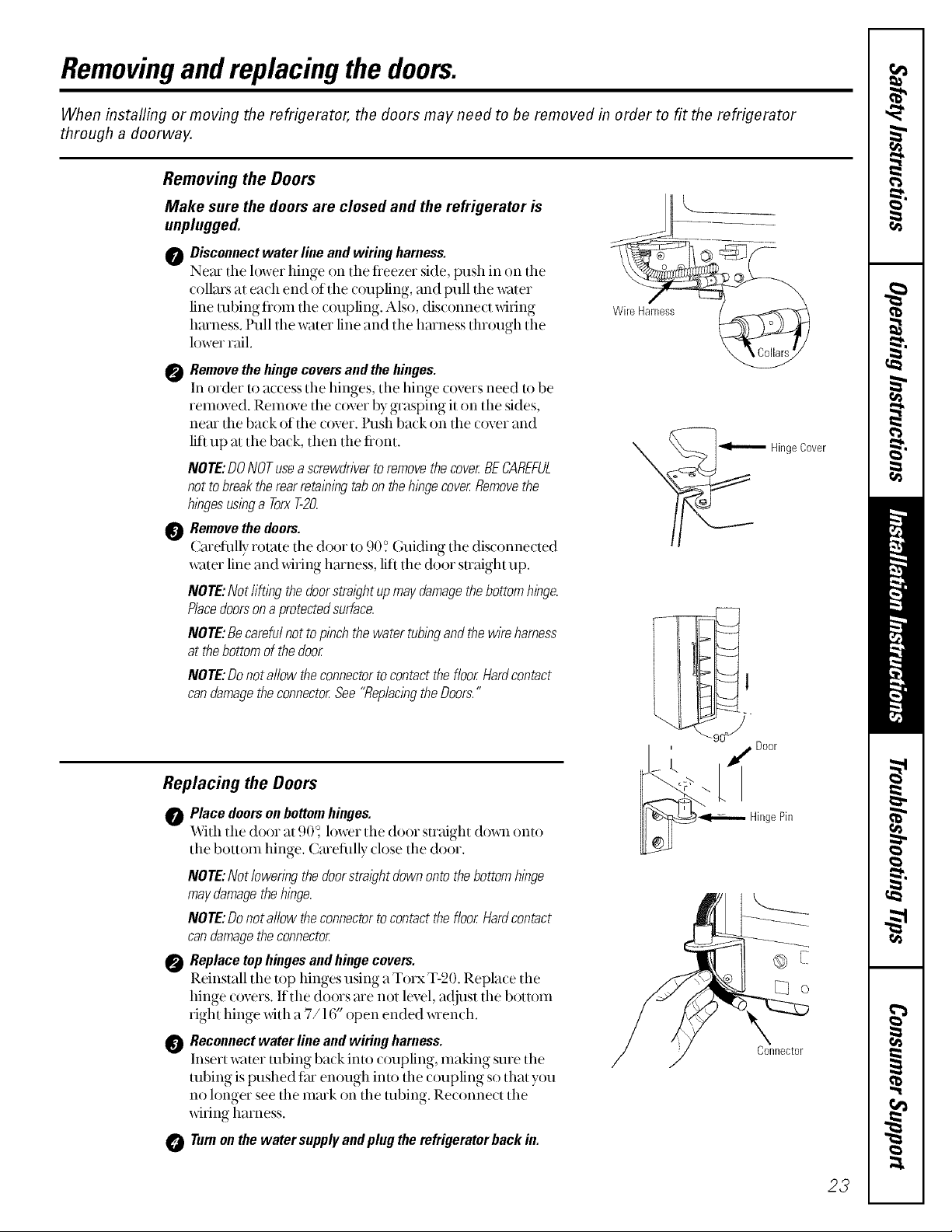
Removingandreplacing the doors.
When instafling or moving the refrigerator, the doors may need to be removed in order to fit the refrigerator
through a doorway.
Removing the Doors
Make sure the doors are closed and the refrigerator is
unplugged.
0 Disconnect water line and wiring harness.
Nero tile lower hinge on the fleezer side, push in on tile
collars at each end of tile c()upling, and pull the w;tter
line robing fl'om tile coupling. Also, disconnect _dfing
hmness. Pull tile water line and the harness through the
lower rail.
0 Remove the hinge covers and the hinges.
In order to access the hinges, the hinge covers need to be
rem()ved. Remove the c()ver by grasping it on tile sides,
near the back of the cover, l'ush back on the cover and
lift up at the back, then the fiont.
NOTE:DONOTusea screwdriver toremove the cover BECAREFUL
not to break therear retalbing tab on the hinge cover Removethe
hbges usbg a TorxT-20.
Remove the doors.
Cmetully rotate the door to 90 ? Guiding the dis(onne(ted
water line and _dring harness, lift tile door smdght up.
NOTE: Not li@bgthe doorstraight upmay damagethe bottom hinge.
Placedoorsona protectedsurface.
NOTE:Becareful not to pinch the water tubingand the wire harness
at thebottom of the door
NOTE:Do not allow theconnector tocontact the floor Hardcontact
can damage theconnector See "Replacingthe Doors."
Wire Harness%
-- HingeCover
Replacing the Doors
Place doors on bottom hinges.
With tile door at .0()_h)wer the door maight down onto
the bottom hinge. Cmefillly close the door.
NOTE:Notloweringthedoorstraightdownontothebottomhinge
maydamagethehinge.
NOTE'.Donotallow theconnectortocontactthefloorHardcontact
candamagetheconnector
Replacetophingesandhingecovers.
Reinstall tile top hinges using a Torx T-20. Replace the
hinge c()vers. If tile doors are not level, a(ljust tile bottom
right hinge with a 7/16" open ended x_aench.
Reconnectwaterlineandwiringharness.
Insert water robing back into coupling, making sure the
robing is pushed fro enough into the coupling so that you
no longer see the mark on the robing. Reconnect the
_dfing harness.
Turnonthewater supplyandplugtherefrigeratorbackin.
I ' _ Door
_ HingePin
Connector
23
Installation
Refrigerator
Instructions
Models 21,23, 25, 27 & 29
I Questions?Call800.GE.CARES(800.432.2737)or Visit ,)ur Websit eat: www.GEAppliances.comIn Canada,call 1.800.361.3400orvisit,)1,,Websiteat:www.geappliances.ca
BEFORE YOU BEGIN
Read these instructions completely and carefully.
• IMPORTANT - Savethes+
instru_ tions for local inspe( tor's use.
•IMPORTANT - Obs+,v+all
governing codes and ordinances.
• Note to Installer - Be sure to leave these
instructions with the Consun, er.
. Note to Consumer - Keep these instrmtions
ibr flmne referem e.
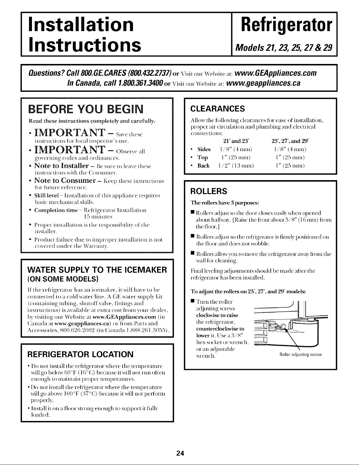
CLEARANCES
Allow the fi)llo_dng dearan(es for ease of installation,
proper air drculation and plumbing and ele_trkal
COlmections:
21' and 23' 25', 27', and 29'
• Sides 1/8" (4ram) 1/8" (4ram)
• Top 1" (25 ram) 1" (25 ram)
• Back 1/2" (13 ram) 1" (25 ram)
ROLLERS
" Skill level -Installation of this appliance requires
basic mechanical skills.
• Completion time - Refligerator Installation
15 minutes
• Proper installation is the responsibility of the
installer.
" Product tifilure due to in, proper installation is not
( overed under the Warranty.
WATER SUPPLY TO THE ICEMAKER
(ON SOME MODELS)
The milers have 3 purposes:
• Rollers at!just so the door closes easily when opened
about half, ray. [Raise the hont about a/8 (16 inn,) fioln
the floor.]
• Rollers at!just so the refrigerator is firmly positioned on
the floor and does not wobble.
• Rollers alh)wyou to move the refiigerator away fiom the
wall fi)r (leaning.
Final leveling ac!jt_stinelns shouM be made after the
refrigerator has been installed.
I
If the refligerator has an icemaker, it will have to be
COlmected to a cold water line. AGE water supply kit
(coi, tailfing tubing, shutoff valve, fittings and
instructions) is available at extra cost fiom your dealer,
by visiting our Website at www.GEAppliances.com (in
Canada at www.geappliances.ca) or fiom Parts and
Accessories, 800.626.2002 (in Canada 1.888.261.3055).
REFRIGERATOR LOCATION
• Do not install the refligerator where the telnperamre
will go below 60°F (16°C) becm_se it will not i11i, oriel,
enough to maintain proper temperatures.
• Do not install the refiigerator where the temperature
will go above 100 °F (37 °() because it will not perlorm
properly.
• Install it on a floor strong enough to support it hilly
loaded.
To adjust the milers on 25', 27', and 29' models:
Turn the roller
a(!justing screws
clockwise to raise
the retiigera/or,
counterclockwise to
lower it. Use a 3/8"
hex socket or x_Tench,
or an a_{justable
x_aench.
24
k
Roller adjusting screw
Installation Instructions
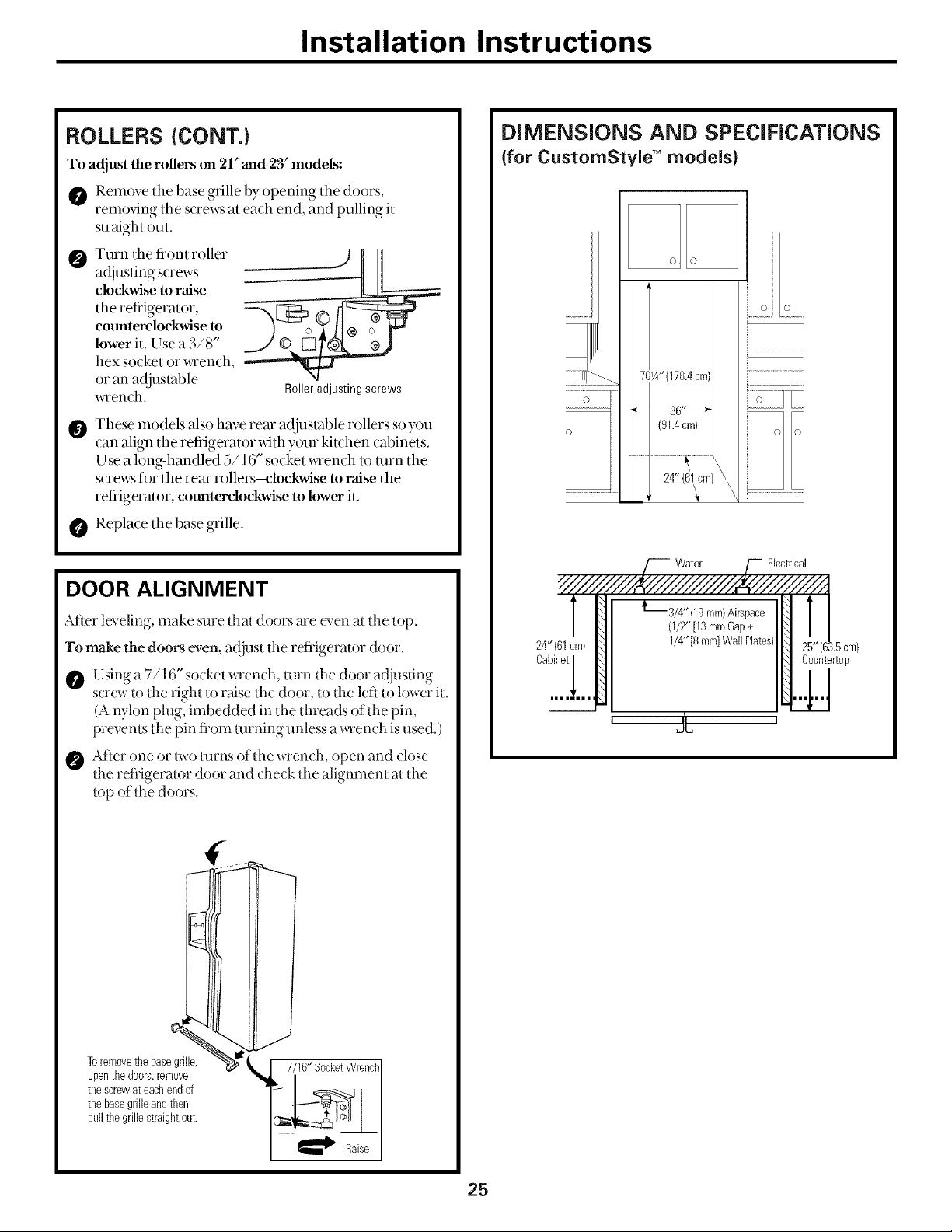
ROLLERS {CONT.)
To adjust the rollers on 21' and 23' models:
O Remove tile base grille by opening the doors,
removing the s(rews at ea(h end, and pulling it
straight out.
Turn the front roller
ac!justing s(rews
clockwise to raise
the refiigerator,
counterclockwise to
lower it. Use a 3/8"
hex socket or x,Tench,
or an a({jusmble
x_Tench.
These models also have rear a([iustable rollers soyou
can align the refiigerator _dth your kitchen cabinets.
L sea long-handled b/16 socketx_Tenchto turn the
Y _ -it
screws fi)r the rear rollers--mlockwise to raise the
refrigerator, counterclockwise to lower it.
Replace tlle base grille.
Roller adjusting screws
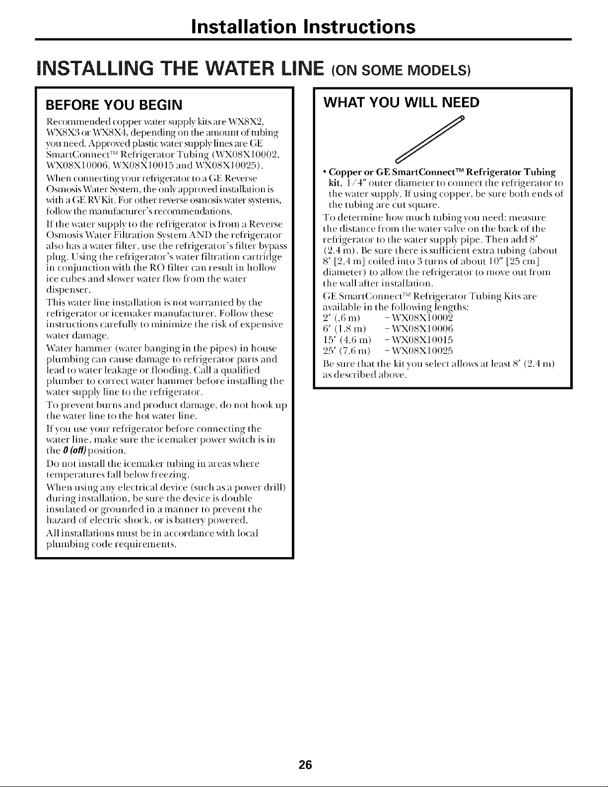
DIMENSIONS AND SPECIFICATIONS
(for CustomStyle" models}
o o
..... .....
701A"(178.4cm)
o
o
" 36"_
(91.4cm}
.......................................24" (61fm}_.................
Water Electrical
DOOR ALIGNMENT
After ]exeling, make sure flint doors are exen at tl_e rap.
To make the doors even, adjust tlle refligeramr door.
Lstag a //16 socket wrench, mrn d*e d(_or adiusdng
screw U)[l_e right 1oraise [he door, u) [l_e left u) lower iL
(A nylon plug, imbedded in the threads of the pin,
pre_ enls Ihe pin fl't)m turning unless a wrench is used. )
After one or two turns of din wrench, open and close
Ihe refligerator door and (hetk II_e alignmenI aI II_e
lop of Ihe doors.
24" (61cm)
Cabinet
/4" (lg ram)Airspace
(1/2"[13mmGap+
1/4"[8 mm]WallPlates)
' 2C 1
1.5cm}
Countertop
Toremovethe basegrille,
opentbedoors,remove
tbescrewateachendof
thebasegrilleandthen
pail thegrillestraightout.
7/I 6"SocketWrench]
aiseI
25
Installation Instructions
iNSTALLiNG THE WATER LiNE (oNSOMEMODELS)
BEFORE YOU BEGIN
Recommended copper water supply kits are WX8X2,
WX8X3 or WXSX4, depending on the mn()unt of robing
you need. Appr()ved plastic water supply lines are GE
Smart( onnec/TM Refligerator Tubing (WX08X10002,
WX08X 10006, WX08X 10/!15 and WX/!8X 10025).
When connecting _)ur refiigerator to a GE Reverse
Osmosis Water System, the only appr()ved installation is
with a GE RVKit. For other reverse osmosis water systems,
fi)llow the mam_tilctmer's recommendations.
If the water supply to the refligerator is flom a Reverse
Osmosis Water Fihration System AND the refligerator
also has a water filter, use the refligerator's fiher bypass
plug. Using the refligerator's water fihration cartridge
in conjunction with the RO fiher can resuh in hollow
ice cubes and slower water flow flom the water
dispenser.
This water line installation is not warranted by the
refligerator or icemaker manufacturer. Follow these
instructions careflflly to minimize the risk of expensive
water damage.
Water hammer (water banging in the pipes) in house
plumbing can cause damage to refligerator parts and
lead to water leakage or flooding. Call a qualified
plumber to correct water hammer befine installing the
water supply line to the refrigerator.
To prevent burns and product damage, do not hook up
the water line to the hot water line.
If you use your refligerator before connecting the
water line, make sure the icemaker power switch is in
the 0 (o#)position.
Do not install the icemaker robing in areas where
temperatures tall below fleezing.
When using aW electrical device (such as a power drill)
during installation, be sure the device is double
insulated or grounded in a manner to prevent the
hazard of electric shock, or is battery powered.
All installations must be in accordance with local
plumbing code requirements.
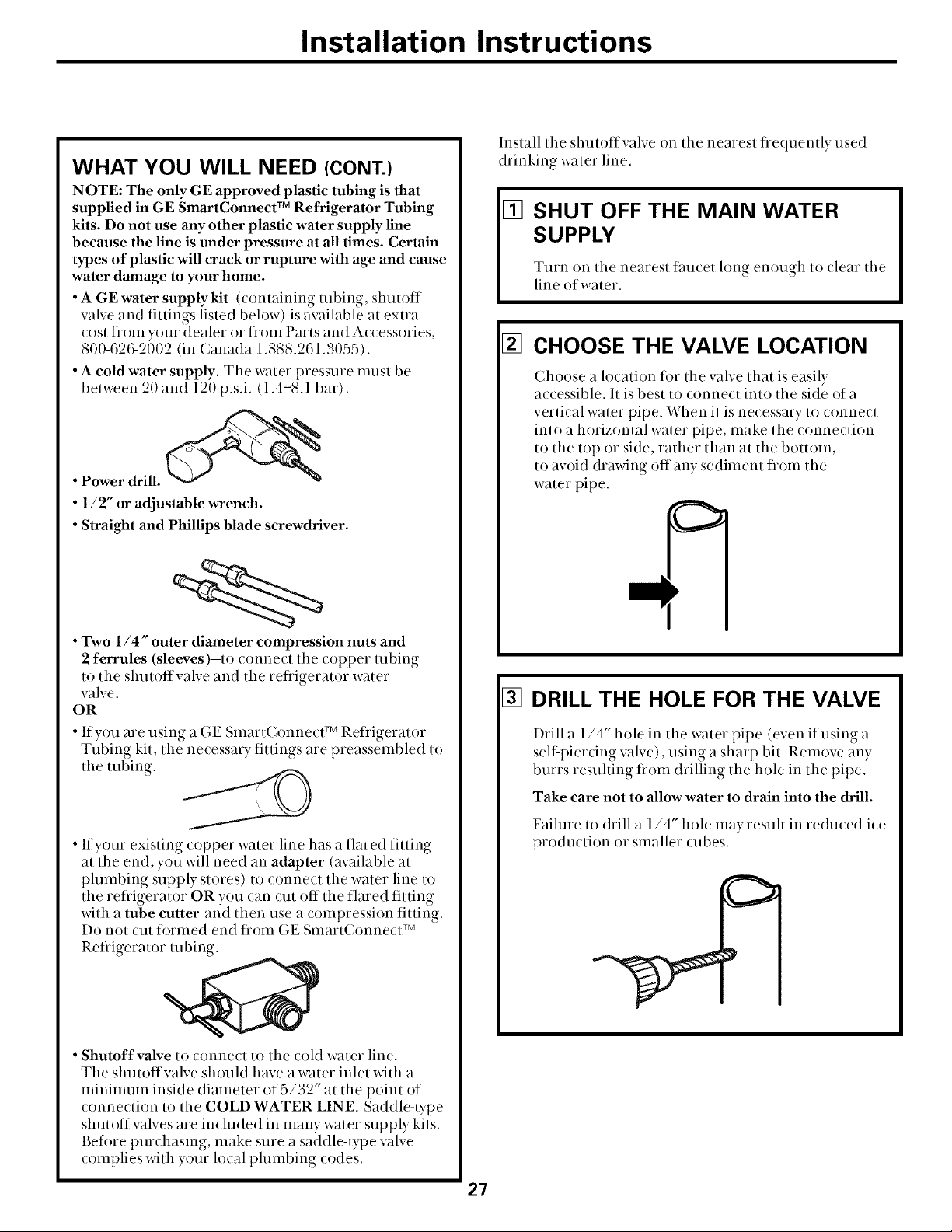
WHAT YOU WILL NEED
J
• Copper or GE SmartConnect TM Refrigerator Tubing
kit, 1/4" outer diameter to connect the refligerator to
the water supply. If using copper, be sure both ends of
the tubing are cut square.
To determine how much robing you need: measure
the distance flom the water valve on the back of the
refligerator to the water supply pipe. Then add 8'
(2.4 m). Be sure there is sufficient extra tubing (about
8' [2.4 m] coiled into 3 turns of about 10" [25 cm]
diameter) to allow the refligerator to move out flom
the wall after installation.
GE SmartConnecl TM Refligerator Tubing Kits are
available in the fi)llowing lengths:
2' (.6 m) - WXOSX10002
6' (1.8 m) - WX08X10006
15' (4.6 m) - WX/!8Xl0015
25' (7.6 m) - WX08X10025
Be sure that the kit you select allows at least 8' (2.4 m)
as described above.
26
Installation Instructions
WHAT YOU WILL NEED (CONT.)
NOTE: The only GE approved plastic tubing is that
supplied in GE SmartConnect TM Refrigerator Tubing
kits. Do not use any other plastic water supply line
because the line is under pressure at all times. Certain
types of plastic will crack or rupture with age and cause
water damage to your home.
• A GEwater supplykit (containing robing, shutoff
valve and fittings listed below) is available at extra
cost flom vour dealer or flom Parts and Accessories,
800-626-2602 (in (anada 1.888.261.3055).
• A cold water supply. The water pressure must be
between 20 and 120 p.s.i. (1.4-8.1 bar).
• Power drill.
• 1/2" or adjustable wrench.
• Straight and Phillips blade screwdriver.
Install the shutoffvalve on the nearest tiequemly used
drinking water line.
[] SHUT OFF THE MAIN WATER
SUPPLY
Turn on the nearest tim(el long enough to (lear the
line of water.
[] CHOOSE THE VALVE LOCATION
Choose a location tot the valve that is easily
accessible. It is best to connect into the side of a
vertical water pipe. When it is necessa_ y to connect
into a horizontal water pipe, make the connection
to the top or side, rather than at the bottom,
to avoid drawing off any sediment flom the
water pipe.
• Two 1/4" outer diameter compression nuts and
2 ferrules (sleeves)--to _onne_t the _opper robing
to the shutotfvalve and the reliigerator water
valve.
OR
• If you are using a GE Smart( onnecff v Refiigerator
Tubing kit, the necessa_ y fittings are preassembled to
tlle robing.
• If your existing copper water line has a flared fitting
at the end, you will need an adapter (available at
plumbing supply stores) to connect the water line to
the refligerator OR you can cut off the flared fitting
with a tube cutter and then use a compression fitting.
Do not cut formed end flom GE Smart( onnect TM
Refiigerator robing.
• Shutoff valve to connect to the cold water line.
The shutoffvalve should have a water inlet with a
minimum inside diameter of 5/32" at the point of
connection to the COLD WATER LINE. Saddle-type
shutoffvalves are included in many water supply kits.
Betore purchasing, make sure a saddleqype valve
complies with your local plumbing codes.
[] DRILL THE HOLE FOR THE VALVE
I)rill a 1/4" hole in the water pipe (even if using a
seltZpierdng valve), using a sharp bit. Remove any
burrs resuhing tiom drilling the hole in the pipe.
Take care not to allow water to drain into the drill.
Failure to drill a 1/4" hole may resuh in reduced ice
production or smaller cubes.
27
Installation Instructions
INSTALLING THE WATER LINE (CONT.)
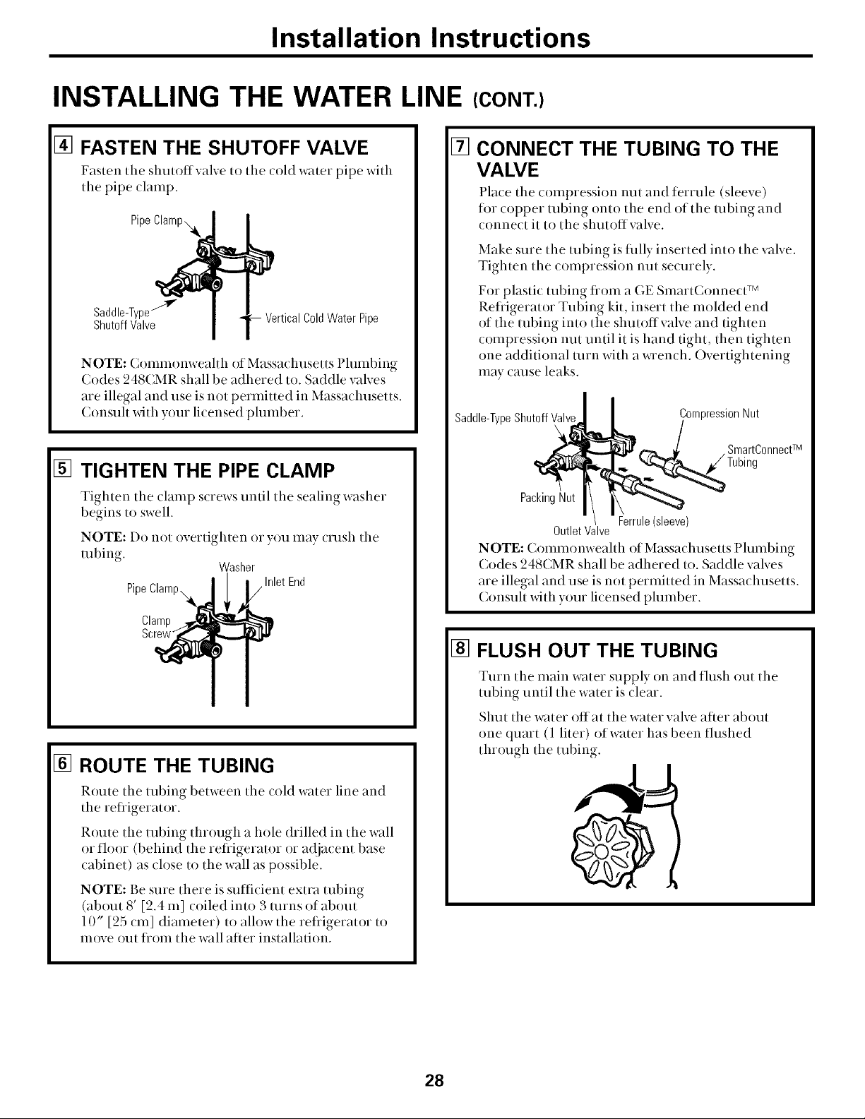
[] FASTEN THE SHUTOFF VALVE
Fasten tile shutoffvalve tr) tile (old water pipe with
tile pipe (lamp.
Pipe
Saddle-Type""_ C01dWater Pipe
ShutoffValve
NOTE: Crmnnrmweahh of Massachusetts Plumbing
Cr)des 248CMR shall be adhered to. Saddle valves
are illegal and use is not perlnitted in Massachusetts.
Crmsuh _dth your licensed phunber.
[] TIGHTEN THE PIPE CLAMP
Tighten the clamp screws until the sealing washer
begins to swell.
NOTE: Do not overtighten or you may crush tile
robing.
Pipe
Clamp
Screw"
Washer
Inlet End
r •
[] CONNECT THE TUBING TO THE
VALVE
Place the compression nut and ferrule (sleeve)
for copper tubing onto the end of the robing and
crmnect it tr) the slmtr)flvalve.
Make sure the tubing is fully inserted into the valve.
Tighten the compression nut securely.
For plastic tubing flom a GE SmartConnect TM
Refligerator Tubing kit, insert the molded end
of the tubing into the shutoffvalve and tighten
compression nut until it is hand tight, then tighten
one additional mrn with a _Tench. Overtightening
may cause leaks.
I
Saddle-TypeShutoffValveI CompressionNut
SmartConnectTM
PackingNut
OutletValve
NOTE: ( rmnnrmweahh of Massachusetts 1)hHnbing
Codes 248( MR shall be adhered to. Saddle valves
are illegal and use is not permitted in Massa( husetts.
Consuh _dth your li(ensed plumber.
[] FLUSH OUT THE TUBING
Ferrule(sleeve)
[] ROUTE THE TUBING
Route the tubing between tile cold water line and
the refiigerator.
Route tile tubing through a hole drilled in the wall
or floor (behind the refligerator or adja( ent base
(abinet) as ( lr)se tr) the wall as possible.
NOTE: Be stlre there is sufficient extra tubing
(about 8' [2.4 In] coiled into 3 turns of about
10" [25 cm] diameter) tr) allow the reliigerator to
move out fiom the wall after installation.
Turn the inain water supply on and flush out tile
tubing until tile water is clear.
Shut tile water offal the water valve after about
one quart (1 liter) of water has been flushed
through the tubing.
28
Installation instructions
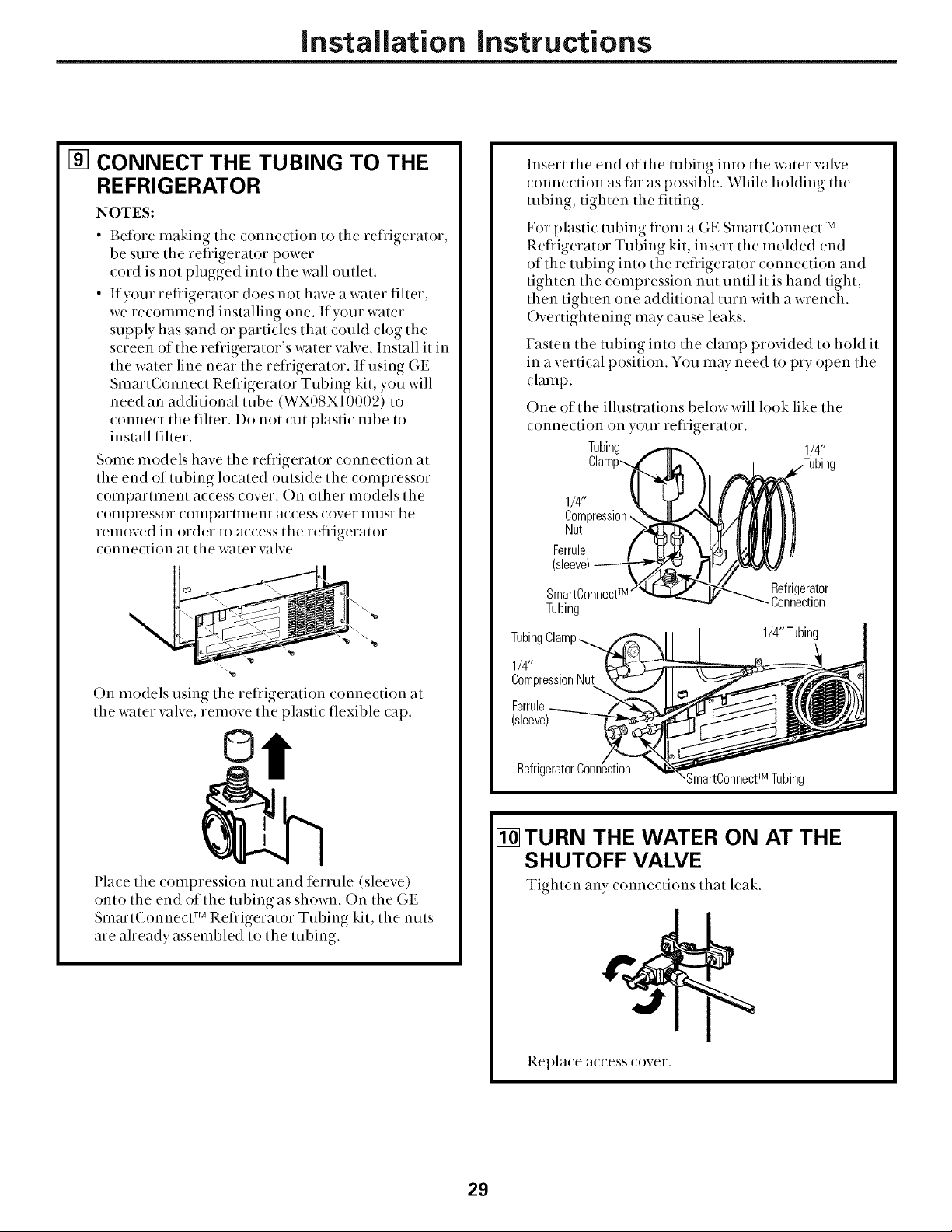
[] CONNECT THE TUBING TO THE
REFRIGERATOR
NOTES:
Befi)re making the connection to the refligerator,
be sure the refligerator power
cord is not plugged into the wall outlet.
If your refligerator does not have a water fiher,
we recommend installing one. If your water
supply has sand or particles that could clog the
screen of the refligerator's water valve. Install it in
the water line near the refligerator. If using GE
SmartConnect Refligerator Tubing kit, you will
need an additional tube (WX08X10002) to
connect the fiher. Do not cut plastic tube to
install fiher.
Some models have the refligerator connection at
the end of robing located outside the compressor
compartment access cover. On other models the
compressor compartment access cover must be
removed in order to access the refligerator
connection at the water valve.
On mr)dels using the refligeratirm crmnectirm at
the water valve, remove the plastic flexible cap.
Insert the end of the tubing into the water valve
_onne_tion as far as possible. While holding the
tubing, tighten the fitting.
For plastic tubing flom a GE SmartConnecff v
Refligerator Tubing kit, insert the molded end
of the tubing into the refligerator connection and
tighten the compression nut until it is hand tight,
then tighten one additional turn _dth a wrench.
Overtightening may cause leaks.
Fasten the tubing intr) the clamp provided to hold it
in a vertk al pr)sitirm. You may need to pry open the
_lamp.
One of the illustrations below will look like the
crmnectirm rm yO[li refrigerator.
Tubing 1/4"
1/4"
Compression,.,
Nut
Ferrule
SmartConnectw
Tubing
Tubing Clamp
1/4"
CompressionNut
Ferrule
(sleeve)
Refrigerator
Connection
1/4"Tubing
©
Place the compression nut and terrule (sleeve)
onto the end of the tubing as shown. On the GE
SmartConnect TM Refligerator Tubing kit, the nuts
are aheady assembled to the robing.
Refrigerator
SmartConnectTMTubing
[] TURN THE WATER ON AT THE
SHUTOFF VALVE
Tighten any ( r)nne(tir)ns that leak.
Replace access cover.
29
Installation instructions
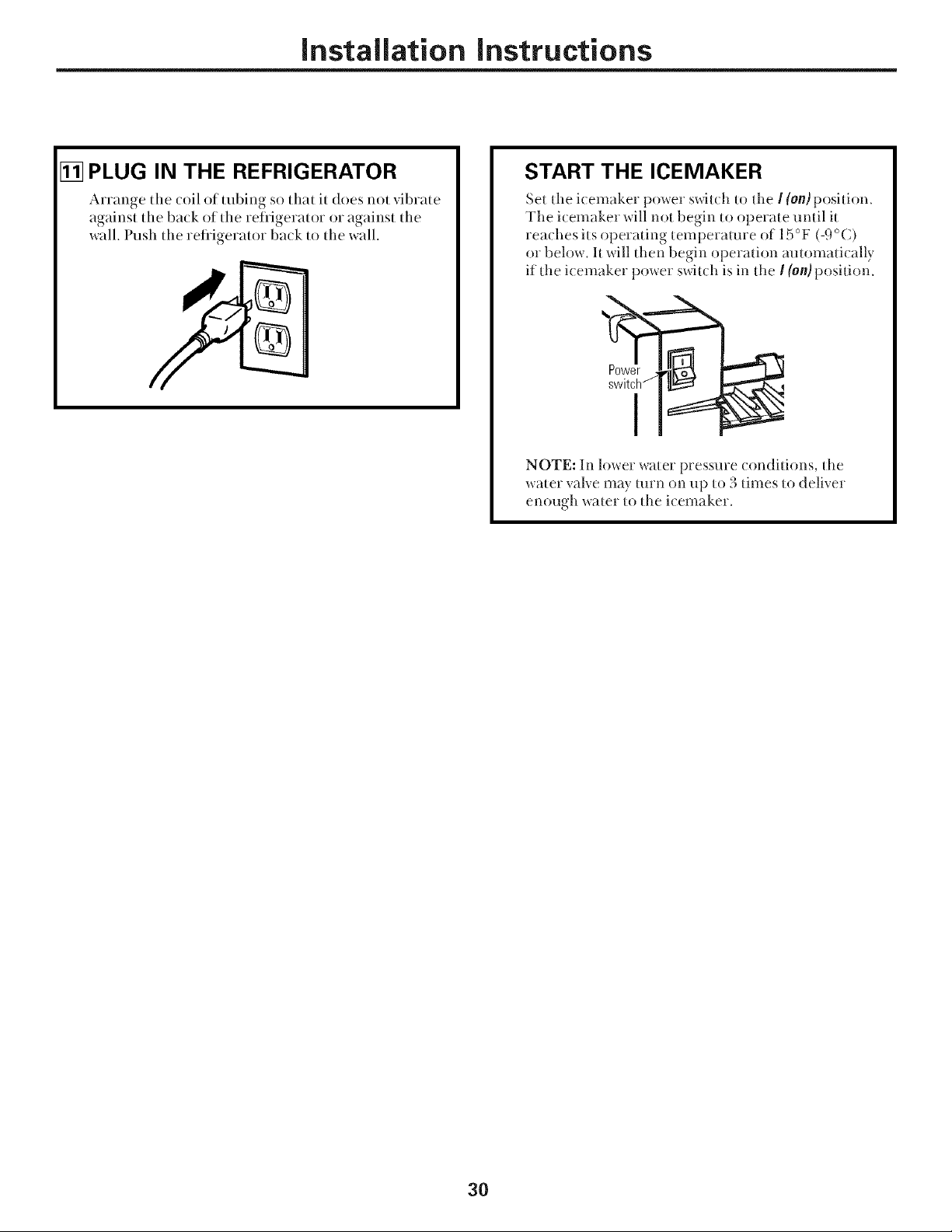
[] PLUG IN THE REFRIGERATOR
Arrange tile coil of tubing so that it does not vibrate
against the back of the refligerator or against the
wall. Push the refligerator back to the wall.
START THE ICEMAKER
Set the icemaker power s_itch to the I (on)position.
The icemaker will not begin to operate until it
tea( hes its operating temperature of 15 °F (-9 °C)
or below. It will then begin operation automati( ally
if tl_e i( emaker power switch is in tl_e ! (on) position.
NOTE: In lower water pressure conditions, tile
water valve may turn on up to 3 times to deliver
enough water to tl_e icemaker.
30
 Loading...