


 Loading...
TransPort™ PT878GC
Portable Gas Flowmeter

April 2004
Process Control Instruments
TransPort™ PT878GC
Portable Gas Flowmeter
Operation & Installation Guide |
910-229A |

April 2004
Warranty
Each instrument manufactured by GE Panametrics is warranted to be free from defects in material and workmanship. Liability under this warranty is limited to restoring the instrument to normal operation or replacing the instrument, at the sole discretion of GE Panametrics. Fuses and batteries are specifically excluded from any liability. This warranty is effective from the date of delivery to the original purchaser. If GE Panametrics determines that the equipment was defective, the warranty period is:
•one year from delivery for electronic or mechanical failures
•one year from delivery for sensor shelf life
If GE Panametrics determines that the equipment was damaged by misuse, improper installation, the use of unauthorized replacement parts, or operating conditions outside the guidelines specified by GE Panametrics, the repairs are not covered under this warranty.
The warranties set forth herein are exclusive and are in lieu of all other warranties whether statutory, express or implied (including warranties or merchantability and fitness for a particular purpose, and warranties arising from course of dealing or usage or trade).
iii

April 2004
Return Policy
If a GE Panametrics instrument malfunctions within the warranty period, the following procedure must be completed:
1.Notify GE Panametrics, giving full details of the problem, and provide the model number and serial number of the instrument. If the nature of the problem indicates the need for factory service, GE Panametrics will issue a RETURN AUTHORIZATION number (RA), and shipping instructions for the return of the instrument to a service center will be provided.
2.If GE Panametrics instructs you to send your instrument to a service center, it must be shipped prepaid to the authorized repair station indicated in the shipping instructions.
3.Upon receipt, GE Panametrics will evaluate the instrument to determine the cause of the malfunction.
Then, one of the following courses of action will then be taken:
•If the damage is covered under the terms of the warranty, the instrument will be repaired at no cost to the owner and returned.
•If GE Panametrics determines that the damage is not covered under the terms of the warranty, or if the warranty has expired, an estimate for the cost of the repairs at standard rates will be provided. Upon receipt of the owner’s approval to proceed, the instrument will be repaired and returned.
iv
April 2004
Table of Contents
Chapter 1: Features and Capabilities
Overview. . . . . . . . . . . . . . . . . . . . . . . . . . . . . . . . . . . . . . .1-1
System Description. . . . . . . . . . . . . . . . . . . . . . . . . . . . . . .1-3
The Flowcell. . . . . . . . . . . . . . . . . . . . . . . . . . . . . . . . .1-3
Electronics Package . . . . . . . . . . . . . . . . . . . . . . . . . . .1-4
Theory of Operation . . . . . . . . . . . . . . . . . . . . . . . . . . . . . .1-5
Chapter 2: Initial Setup
Making Electrical Connections. . . . . . . . . . . . . . . . . . . . . .2-2 Power Connections. . . . . . . . . . . . . . . . . . . . . . . . . . . .2-2 Transducer Connections. . . . . . . . . . . . . . . . . . . . . . . .2-3 Analog Input/Output Connections . . . . . . . . . . . . . . . .2-3 The Infrared Wireless Interface . . . . . . . . . . . . . . . . . .2-4
Charging and/or Replacing Batteries . . . . . . . . . . . . . . . . .2-5 Charging the Batteries . . . . . . . . . . . . . . . . . . . . . . . . .2-5 Replacing the Batteries . . . . . . . . . . . . . . . . . . . . . . . .2-6 Powering On and Off . . . . . . . . . . . . . . . . . . . . . . . . . . . . .2-7 Using the Screen and Keypad. . . . . . . . . . . . . . . . . . . . . .2-10 Screen. . . . . . . . . . . . . . . . . . . . . . . . . . . . . . . . . . . . .2-10 Keypad . . . . . . . . . . . . . . . . . . . . . . . . . . . . . . . . . . . .2-12 Obtaining On-Line Help. . . . . . . . . . . . . . . . . . . . . . . . . .2-14
Chapter 3: Installing the Dampening Material, Transducers and Fixtures
Application Requirements . . . . . . . . . . . . . . . . . . . . . . . . .3-3 Preparing the Pipe. . . . . . . . . . . . . . . . . . . . . . . . . . . . . . . .3-5 Performing a Pipe Survey . . . . . . . . . . . . . . . . . . . . . .3-6 Obtaining the Transducer Spacing . . . . . . . . . . . . . . . .3-8 Installing the V Series Clamping Fixture and Transducers 3-9 Installing the Fixture . . . . . . . . . . . . . . . . . . . . . . . . . .3-9 Installing the Transducers . . . . . . . . . . . . . . . . . . . . .3-11 Installing the PI Fixture and Transducers . . . . . . . . . . . . .3-13 Surveying the Pipe . . . . . . . . . . . . . . . . . . . . . . . . . . .3-13 Installing the First Bracket with a Chain . . . . . . . . . .3-16 Installing the Second Bracket with a Chain . . . . . . . .3-17 Installing the Transducers . . . . . . . . . . . . . . . . . . . . .3-18
v
April 2004
Table of Contents (cont.)
Chapter 3: Installing the Dampening Material, Transducers and Fixtures (cont.)
Installing Dampening Material. . . . . . . . . . . . . . . . . . . . .3-20 Installing DMP-1 Dampening Material with CFG-V Series Fixtures . . . . . . . . . . . . . . . . . . . . . . . . . . . . . .3-21 Installing DMP-1 Dampening Material with PI
Fixture . . . . . . . . . . . . . . . . . . . . . . . . . . . . . . . . . . . .3-24 Installing DMP-3 Compound with All Fixtures. . . . .3-26 Installing the PDJ Dampening Jacket . . . . . . . . . . . .3-28
Chapter 4: Programming Site Data
Entering the Program Menu . . . . . . . . . . . . . . . . . . . . . . . .4-2 Entering Transducer Parameters. . . . . . . . . . . . . . . . . . . . .4-3 Entering Pipe Parameters . . . . . . . . . . . . . . . . . . . . . . . . . .4-7 Entering Pipe Lining Parameters . . . . . . . . . . . . . . . . . . .4-11 Entering Fluid Types and Speeds . . . . . . . . . . . . . . . . . . .4-13 Entering the Signal Path Parameters. . . . . . . . . . . . . . . . .4-15
Path Parameters for Clamp-On Transducers.. . . . . . .4-16 Entering the Standard Volume/
Mass Flow Parameters . . . . . . . . . . . . . . . . . . . . . . . . . . .4-17 Entering Inputs in the Standard Volume Option . . . .4-19 Entering Mass Flow Parameters. . . . . . . . . . . . . . . . .4-22 Entering Skan/Measure Parameters . . . . . . . . . . . . . . . . .4-24 Entering Skan/Measure Integrate Parameters . . . . . .4-28 Entering Skan/Measure Count Parameters. . . . . . . . .4-30 Entering Skan/Correlation Parameters. . . . . . . . . . . .4-32 Entering Analog Inputs. . . . . . . . . . . . . . . . . . . . . . . . . . .4-34 Entering General-Purpose Analog Inputs . . . . . . . . .4-34
Entering Analog Inputs in Standard Volume or Mass Flow Option . . . . . . . . . . . . . . . . . . . . . . . . . . . . . . . .4-37
Entering the Analog Output . . . . . . . . . . . . . . . . . . . . . . .4-39 Entering the Digital Output . . . . . . . . . . . . . . . . . . . . . . .4-42 Entering User Functions . . . . . . . . . . . . . . . . . . . . . . . . . .4-46 Entering Correction Factors . . . . . . . . . . . . . . . . . . . . . . .4-50 Entering Reynolds Correction . . . . . . . . . . . . . . . . . .4-50 Entering a Calibration Factor. . . . . . . . . . . . . . . . . . .4-53
vi
April 2004
Table of Contents (cont.)
Chapter 5: Creating and Managing Sites
The Site Manager . . . . . . . . . . . . . . . . . . . . . . . . . . . . . . . .5-2 Creating a New Site . . . . . . . . . . . . . . . . . . . . . . . . . . .5-4 Opening an Existing Site . . . . . . . . . . . . . . . . . . . . . . .5-6 Saving a Site. . . . . . . . . . . . . . . . . . . . . . . . . . . . . . . . .5-7 Saving a Site with a Different Name . . . . . . . . . . . . . .5-8 Refreshing a Site . . . . . . . . . . . . . . . . . . . . . . . . . . . . .5-9 Renaming a Site . . . . . . . . . . . . . . . . . . . . . . . . . . . . . .5-9 Deleting a Site . . . . . . . . . . . . . . . . . . . . . . . . . . . . . .5-10 Creating a Site Message . . . . . . . . . . . . . . . . . . . . . . .5-11 Printing a File. . . . . . . . . . . . . . . . . . . . . . . . . . . . . . .5-13 Transferring a Site File to a PC . . . . . . . . . . . . . . . . .5-13 Transferring a File as Text . . . . . . . . . . . . . . . . . . . . .5-14 Transferring a File from a PC to the PT878GC . . . . .5-15 Listing Files by Name . . . . . . . . . . . . . . . . . . . . . . . .5-17 Listing Files in Chronological Order . . . . . . . . . . . . .5-17
Chapter 6: Displaying and Configuring Data
The Format Option . . . . . . . . . . . . . . . . . . . . . . . . . . . . . . .6-2 The View Option. . . . . . . . . . . . . . . . . . . . . . . . . . . . . . . . .6-4 The Limits Option. . . . . . . . . . . . . . . . . . . . . . . . . . . . . . . .6-5 The Measurement Option . . . . . . . . . . . . . . . . . . . . . . . . . .6-7 Customizing the Display Screen. . . . . . . . . . . . . . . . . . . . .6-9
Specifying the Number of Displayed Parameters . . .6-10 Customizing Softkeys . . . . . . . . . . . . . . . . . . . . . . . .6-11 Managing Files — The Drive Manager . . . . . . . . . . . . . .6-14 Refreshing a File . . . . . . . . . . . . . . . . . . . . . . . . . . . .6-16 Transferring a File to a PC. . . . . . . . . . . . . . . . . . . . .6-16 Transferring a File from a PC to the PT878GC . . . . .6-17 Deleting a File . . . . . . . . . . . . . . . . . . . . . . . . . . . . . .6-19 Listing Files by Name . . . . . . . . . . . . . . . . . . . . . . . .6-20 Listing Files in Chronological Order . . . . . . . . . . . . .6-20 Accessing Meter Data —The About Option . . . . . . . . . .6-21
vii
April 2004
Table of Contents (cont.)
Chapter 7: Programming Meter Settings
Entering the Meter Menu . . . . . . . . . . . . . . . . . . . . . . . . . .7-2
Selecting Measurement Units. . . . . . . . . . . . . . . . . . . . . . .7-3
The Battery Charger . . . . . . . . . . . . . . . . . . . . . . . . . . . . . .7-5
Entering Date and Time . . . . . . . . . . . . . . . . . . . . . . . . . . .7-7
Changing Date and Time Appearance (Locale) . . . . . . . . .7-9
Adjusting the Contrast . . . . . . . . . . . . . . . . . . . . . . . . . . .7-12
Setting Backlight Timeout . . . . . . . . . . . . . . . . . . . . . . . .7-14
Changing Communications Parameters . . . . . . . . . . . . . .7-15
Resetting Forward and Reverse Totals . . . . . . . . . . . . . . .7-18
Setting Up User Tables . . . . . . . . . . . . . . . . . . . . . . . . . . .7-19
Taking a Bitmap Capture of a Current Screen . . . . . . . . .7-23
viii
April 2004
Table of Contents (cont.)
Chapter 8: Logging Data
Entering the Logging Menu . . . . . . . . . . . . . . . . . . . . . . . .8-2 The Log Manager . . . . . . . . . . . . . . . . . . . . . . . . . . . . . . . .8-3 The File Menu. . . . . . . . . . . . . . . . . . . . . . . . . . . . . . . . . . .8-4 Setting up a New Log. . . . . . . . . . . . . . . . . . . . . . . . . .8-5 Copying (Cloning) a Selected Log. . . . . . . . . . . . . . .8-10 Renaming a Log . . . . . . . . . . . . . . . . . . . . . . . . . . . . .8-11 Deleting a Log . . . . . . . . . . . . . . . . . . . . . . . . . . . . . .8-11 Deleting All Logs. . . . . . . . . . . . . . . . . . . . . . . . . . . .8-12 Refreshing a Log . . . . . . . . . . . . . . . . . . . . . . . . . . . .8-12 Printing a Log. . . . . . . . . . . . . . . . . . . . . . . . . . . . . . .8-13 Transferring a Log to a PC. . . . . . . . . . . . . . . . . . . . .8-13 The Log Menu . . . . . . . . . . . . . . . . . . . . . . . . . . . . . . . . .8-14 Stopping (Pausing) a Log. . . . . . . . . . . . . . . . . . . . . .8-15 Restarting a Log . . . . . . . . . . . . . . . . . . . . . . . . . . . . .8-15 Ending a Log . . . . . . . . . . . . . . . . . . . . . . . . . . . . . . .8-15 Pausing All Logs . . . . . . . . . . . . . . . . . . . . . . . . . . . .8-16 Restarting All Logs . . . . . . . . . . . . . . . . . . . . . . . . . .8-16 Ending All Logs . . . . . . . . . . . . . . . . . . . . . . . . . . . . .8-16 View All Sites . . . . . . . . . . . . . . . . . . . . . . . . . . . . . .8-16 The View Menu . . . . . . . . . . . . . . . . . . . . . . . . . . . . . . . .8-17 Displaying Log Details . . . . . . . . . . . . . . . . . . . . . . .8-18 Displaying Log Data in Graphical Form . . . . . . . . . .8-19 Displaying Log Data in Spreadsheet Form . . . . . . . .8-22 The Sort Menu . . . . . . . . . . . . . . . . . . . . . . . . . . . . . . . . .8-23 Listing Logs by Name . . . . . . . . . . . . . . . . . . . . . . . .8-23 Listing Logs in Chronological Order . . . . . . . . . . . . .8-23
ix
April 2004
Table of Contents (cont.)
Chapter 9: Servicing the PT878GC
Entering the Service Menu . . . . . . . . . . . . . . . . . . . . . . . . .9-2 Printing Reports . . . . . . . . . . . . . . . . . . . . . . . . . . . . . . . . .9-3 Setting up the Thickness Gauge . . . . . . . . . . . . . . . . . . . . .9-5 Measuring Pipe Wall Thickness . . . . . . . . . . . . . . . . . . . . .9-7 Entering the Material and Sound Speed. . . . . . . . . . . .9-7 Measuring Thickness in Numeric Format . . . . . . . . . .9-9 Displaying the Receive Signal in Graphical Format .9-10 Calibrating the Thickness Gauge Transducer . . . . . .9-12 Calculating Velocity (Pipe Material Sound Speed) . .9-14 Programming the Thickness Gauge . . . . . . . . . . . . . . . . .9-17 Displaying Diagnostic Parameters . . . . . . . . . . . . . . . . . .9-20 Calibrating the Analog Output and Inputs . . . . . . . . . . . .9-21 Calibrating the Analog Output. . . . . . . . . . . . . . . . . .9-21 Calibrating Inputs. . . . . . . . . . . . . . . . . . . . . . . . . . . .9-23 Setting up Signal Parameters . . . . . . . . . . . . . . . . . . . . . .9-25 Setting up Signal Parameters . . . . . . . . . . . . . . . . . . .9-26 Setting up the Measurement Mode . . . . . . . . . . . . . .9-28 Setting Up Pulse/Code Parameters. . . . . . . . . . . . . . .9-30 Setting Error Limits . . . . . . . . . . . . . . . . . . . . . . . . . . . . .9-32 The Test Option . . . . . . . . . . . . . . . . . . . . . . . . . . . . . . . .9-35 Testing the Screen . . . . . . . . . . . . . . . . . . . . . . . . . . .9-36 Testing the Keys. . . . . . . . . . . . . . . . . . . . . . . . . . . . .9-37 Testing the Watchdog Timer Circuit . . . . . . . . . . . . .9-38 Setting Impulse Response . . . . . . . . . . . . . . . . . . . . .9-39 Taking Wave Samples for Diagnosis. . . . . . . . . . . . .9-40 Applying a Stored Signal for Diagnosis. . . . . . . . . . .9-40 Testing the Battery . . . . . . . . . . . . . . . . . . . . . . . . . . .9-41 Resetting to Factory Default Parameters . . . . . . . . . . . . .9-42 Updating PT878GC Software . . . . . . . . . . . . . . . . . . . . . .9-43 Updating Software Via IrOBEX . . . . . . . . . . . . . . . .9-44 Updating Software Via IrCOMM . . . . . . . . . . . . . . .9-46
x
April 2004
Table of Contents (cont.)
Chapter 10: Diagnostics and Troubleshooting
Error Code Messages . . . . . . . . . . . . . . . . . . . . . . . . . . . .10-2
Displaying Diagnostic Parameters . . . . . . . . . . . . . . . . . .10-6
Flowcell Problems . . . . . . . . . . . . . . . . . . . . . . . . . . . . . .10-9
Gas Problems . . . . . . . . . . . . . . . . . . . . . . . . . . . . . . .10-9
Pipe Problems. . . . . . . . . . . . . . . . . . . . . . . . . . . . . .10-10
Transducer Problems . . . . . . . . . . . . . . . . . . . . . . . . . . .10-11
xi
April 2004
Table of Contents (cont.)
Chapter 11: Specifications
Operation and Performance . . . . . . . . . . . . . . . . . . . . . . .11-2
Fluid Types. . . . . . . . . . . . . . . . . . . . . . . . . . . . . . . . .11-2
Pipe Sizes . . . . . . . . . . . . . . . . . . . . . . . . . . . . . . . . . .11-2
Pipe Wall Thickness. . . . . . . . . . . . . . . . . . . . . . . . . .11-2
Pipe Materials. . . . . . . . . . . . . . . . . . . . . . . . . . . . . . .11-2
Clamp-On Flow Accuracy (Velocity) . . . . . . . . . . . .11-2
Repeatability . . . . . . . . . . . . . . . . . . . . . . . . . . . . . . .11-2
Range (Bidirectional). . . . . . . . . . . . . . . . . . . . . . . . .11-2
Rangeability (Overall) . . . . . . . . . . . . . . . . . . . . . . . .11-2
Pressure Requirements, Air . . . . . . . . . . . . . . . . . . . .11-3
Pressure Requirements, Other Gases . . . . . . . . . . . . .11-3
Measurement Parameters . . . . . . . . . . . . . . . . . . . . . .11-3
Electronics . . . . . . . . . . . . . . . . . . . . . . . . . . . . . . . . . . . .11-4
Flow Measurement. . . . . . . . . . . . . . . . . . . . . . . . . . .11-4
Enclosures . . . . . . . . . . . . . . . . . . . . . . . . . . . . . . . . .11-4
Dimensions. . . . . . . . . . . . . . . . . . . . . . . . . . . . . . . . .11-4
Display . . . . . . . . . . . . . . . . . . . . . . . . . . . . . . . . . . . .11-4
Keypad . . . . . . . . . . . . . . . . . . . . . . . . . . . . . . . . . . . .11-4
Internal Battery. . . . . . . . . . . . . . . . . . . . . . . . . . . . . .11-4
Battery Charger Input. . . . . . . . . . . . . . . . . . . . . . . . .11-4
Memory . . . . . . . . . . . . . . . . . . . . . . . . . . . . . . . . . . .11-4
Operating Temperature . . . . . . . . . . . . . . . . . . . . . . .11-4
Storage Temperature . . . . . . . . . . . . . . . . . . . . . . . . .11-4
Standard Inputs/Outputs. . . . . . . . . . . . . . . . . . . . . . .11-5
Digital Interfaces . . . . . . . . . . . . . . . . . . . . . . . . . . . .11-5
Site Parameter Programming . . . . . . . . . . . . . . . . . . .11-5
Data Logging . . . . . . . . . . . . . . . . . . . . . . . . . . . . . . .11-5
Display Functions. . . . . . . . . . . . . . . . . . . . . . . . . . . .11-5
European Compliance . . . . . . . . . . . . . . . . . . . . . . . .11-5
Clamp-On Ultrasonic Flow Transducers . . . . . . . . . . . . .11-6
Temperature Range(s) . . . . . . . . . . . . . . . . . . . . . . . .11-6
Transducer Materials . . . . . . . . . . . . . . . . . . . . . . . . .11-6
Fixture Materials . . . . . . . . . . . . . . . . . . . . . . . . . . . .11-6
Mountings . . . . . . . . . . . . . . . . . . . . . . . . . . . . . . . . .11-6
Mounting Couplant . . . . . . . . . . . . . . . . . . . . . . . . . .11-6
Area Classifications . . . . . . . . . . . . . . . . . . . . . . . . . .11-6
Transducer Cables . . . . . . . . . . . . . . . . . . . . . . . . . . .11-7
xii
April 2004
Table of Contents (cont.)
Chapter 11: Specifications (cont.)
Thickness Gauge Option. . . . . . . . . . . . . . . . . . . . . . . . . .11-8
Transducer . . . . . . . . . . . . . . . . . . . . . . . . . . . . . . . . .11-8
Pipe Thickness Range . . . . . . . . . . . . . . . . . . . . . . . .11-8
Pipe Materials. . . . . . . . . . . . . . . . . . . . . . . . . . . . . . .11-8
Accuracy . . . . . . . . . . . . . . . . . . . . . . . . . . . . . . . . . .11-8
Thermal Exposure . . . . . . . . . . . . . . . . . . . . . . . . . . .11-8
Additional Options . . . . . . . . . . . . . . . . . . . . . . . . . . . . . .11-8
PC Communication . . . . . . . . . . . . . . . . . . . . . . . . . .11-8
RS232-to-Infrared . . . . . . . . . . . . . . . . . . . . . . . . . . .11-8
Printer. . . . . . . . . . . . . . . . . . . . . . . . . . . . . . . . . . . . .11-8
Appendix A: Menu Maps
Appendix B: Establishing IR Communications with the PT878GC
Windows 2000/XP . . . . . . . . . . . . . . . . . . . . . . . . . . . B-2 Windows NT4.0 . . . . . . . . . . . . . . . . . . . . . . . . . . . . . B-2 Windows Me/98SE/98/95 . . . . . . . . . . . . . . . . . . . . . B-2
Appendix C: Ultrasonic Thickness Gauge Theory of
Operation
Factors Affecting Performance and Accuracy . . . . . . . . . C-2
Appendix D: Material Safety Data Sheets for Couplants
xiii
April 2004
Chapter 1
Features and Capabilities
The TransPort® Model PT878GC is a transit-time clamp-on gas flowmeter which combines all the features of a full-size gas flowmeter with the advantages of a portable instrument.
This section describes the TransPort features and general system, and explains the theory of operation.
Overview
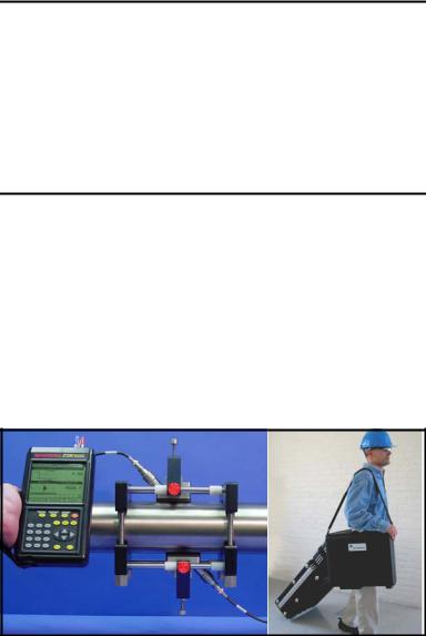
Depending on the selected application, the TransPort PT878GC measures the flow of clean, dry gases in pipes from 4 to 24 in. in diameter. The flowmeter provides one linear 0/4-20 mA analog output of flow velocities or volumetric flow rate of these gases, measuring velocities from ±1 to ±120 ft/sec (±0.3 to ±40 m/sec), along with one selectable frequency or pulsed totalizer output. Figure 1-1 illustrates the PT878GC in use on a typical pipe, along with cases for the PT878GC and accessories.
Figure 1-1: PT878GC in Use and in Transport
Features and Capabilities |
1-1 |

April 2004
Overview (cont.)
The TransPort has the ability to store site data in files which can be accessed at a later time. Within the Main Menu, a set of forms (windows) asks you all the necessary setup information for a particular site. Once you answer the necessary questions, you simply save the information to a file.
The TransPort stores these files and other data in non-volatile memory, which retains the information even if power is turned off. The flowmeter itself runs on rechargeable or alkaline batteries for up to 8 hours.
This small, lightweight flowmeter displays measurements in both numeric and graphical form on a 240 x 200 pixel, EL-backlit LCD graphic screen. The TransPort also has the capability of logging over 100,000 flow data points internally.
Using an infrared communications port, the TransPort can transmit or print logged data, as well as site files, real time data and other stored data.
To assist you, the TransPort is fully equipped with contextsensitive on-line help which is accessible at any time by simply pressing the “?” (Help) key. Internal diagnostic and troubleshooting features help isolate and remedy common flowcell and transducer problems.
1-2 |
Features and Capabilities |

April 2004
System Description
The TransPort is only one part of the flowmeter system. The other part of the system is the flowcell, which consists of the pipe and the transducers.
The Flowcell
The flowcell is that part of the system that uses ultrasonic pulses to interrogate the flow. It consists of the flowcell pipe and the transducers.
A. FLOWCELL PIPE - The flowcell can either be created in the existing piping (for example, by clamping non-wetted transducers onto the pipe), or inserted as a substitute pipe section (spoolpiece). The flowcell must provide mechanical support for the transducers and assure stable conditions for accurate flow measurement.
B. TRANSDUCERS - The transducers convert electrical energy into ultrasonic pulses when in a transmit cycle, and convert the ultrasonic pulses back to electrical energy when in a receive cycle. In other words, they act like loudspeakers when transmitting the signal and microphones when receiving it. In the TransPort system, each transducer acts as both a receiver and transmitter, since a series of ultrasonic pulses are alternately sent upstream and then downstream through the flowcell.
Features and Capabilities |
1-3 |
April 2004
Electronics Package
The TransPort consists of circuits that generate, receive, and measure the travel time of the ultrasonic pulses. It also contains a microcomputer that controls operation and calculates flow measurement parameters. Specific circuits function as follows:
A.TRANSMIT SIGNAL GENERATOR - The transmit signal generator, under control of the microcomputer and timing circuit, synthesizes the signal that drives the transmitter.
B.TRANSMITTER - The transmitter amplifies the signals from the transmit signal generator to a signal that drives the transmit transducer.
C.RECEIVER - The receiver amplifies the received signals to a level suitable for the data acquisition circuitry.
D.DATA ACQUISITION - The data acquisition circuitry digitizes the received signal and stores it in a buffer for processing by the microcomputer.
E.TIMING CIRCUIT - The timing circuit generates the transmitter frequency, receive window, controls the data acquisition circuit and the direction of the transmission.
F.MICROCOMPUTER - The microcomputer controls the TransPort flowmeter’s operation and calculates flow measurements derived from the transmitted and digitized received signals. Also, the microcomputer continually checks for faults and allows the use of built-in diagnostics for troubleshooting.
G.INPUT/OUTPUT - The input/output circuitry allows the flowmeter to indicate the measured flow with the
0/4 to 20-mA current loop, and to output to a printer or other remote device.
1-4 |
Features and Capabilities |

April 2004
Theory of Operation
The TransPort is a transit-time ultrasonic flowmeter. When ultrasonic pulses are transmitted through a moving liquid or gas, the pulses that travel in the same direction as the fluid flow (downstream) travel slightly faster than the pulses that travel against the flow (upstream). The TransPort uses various digital signal processing techniques, including cross-correlation, to determine transit times and then uses the difference in transit times to calculate flow velocity.
During operation, two transducers serve as both ultrasonic signal generators and receivers. When mounted on a pipe, they are in acoustic communication with each other, so that each transducer can receive ultrasonic signals transmitted by the other transducer. Each transducer thus functions as a transmitter generating a certain number of acoustic pulses, and as a receiver for an identical number of pulses.
The flowmeter measures the time interval between transmission and reception of the ultrasonic signals in both directions. When the gas in the pipe is not flowing, the transit-time downstream equals the transit-time upstream. When the gas is flowing, the transit-time downstream is less than the transit-time upstream. The difference between the downstream and upstream transittimes is proportional to the velocity of the flowing gas, and its sign indicates the direction of flow.
Features and Capabilities |
1-5 |

April 2004
Chapter 2
Initial Setup
Before making measurements, you must prepare the TransPort for operation. This includes the following procedures:
•
•
•
•
•
Making Electrical Connections
Charging and/or Replacing Batteries
Powering On and Off
Using the Screen and Keypad
Obtaining On-Line Help
Figure 2-1 below shows the PT878GC in its specially designed case. The interior is molded for optimal protection of the meter and its accessories.
Figure 2-1: The PT878GC and Accessories
Initial Setup |
2-1 |

April 2004
Making Electrical Connections
Before making measurements with the TransPort, you must make all the necessary connections to the unit. This section describes how to connect the following:
•
•
•
•
Power
Transducer
Analog Input/Output
Infrared Interface
Make all connections to the top of the TransPort unit as shown in Figure 2-2 below. Please note that you only need to make the proper transducer connections. The other connections are required for particular functions, but are not necessary for basic operation.
XDCR |
Input/Output |
|
(See Table 2-1 |
||
Upstream |
Downstream |
on page 2-4) |
|
|
|
Infrared |
Power |
|
|
Transceiver |
|
Figure 2-2: Connection Locations
Power Connections
The PT878GC is powered by either a 100-120/200-260 VAC wall mount plug-in module, or by 5 internal Cs-size NiCad high-
energy rechargeable batteries or by a pack of 3.0 Ahr NiMH batteries. (An optional power supplement, part #703-1283, uses 6 AA alkaline batteries.) When you receive the PT878GC, the batteries are not charged; therefore, to make remote measurements using the batteries, follow the instructions on page 2-5 to charge the batteries. In either case, you must connect the power cord to the appropriate terminal as shown in Figure 2-2 above.
2-2 |
Initial Setup |
April 2004
!WARNING!
To ensure the safe operation of the TransPort, you must install and operate it as described in this manual. In addition, be sure to follow all applicable safety codes and regulations for installing electrical equipment in your area.
Transducer Connections
The transducer cables connect to the TransPort with LEMO® coaxial type connectors. Each color-coded cable has a collar labeled UPSTREAM or DOWNSTREAM. Make transducer cable connections to the top of the flowmeter as shown in Figure 2-2 on the previous page. Transducer installation is discussed separately in Chapter 3.
Analog Input/Output Connections
The TransPort provides one 0/4-20 mA current output and two 4 to 20-mA analog inputs with switchable 16-V supply for looppowered temperature transmitters. Connect the inputs/
outputs using a LEMO® multi-pin connector as shown in Figure 2-2 on the previous page. The pin numbers for the connector and the color code for the standard input/output cable are shown in Table 2-1 on the next page.
Initial Setup |
2-3 |
April 2004
Analog Input/Output Connections (cont.)
Table 2-1: Cable Assembly for Analog Inputs/Outputs
|
Wire |
|
Pin Number |
Color |
Description |
|
|
|
1 |
Black |
Analog Out 1 |
2 |
Red |
16 V (switched) |
3 |
White |
Supply Temperature |
4 |
Yellow |
Return Temperature |
5 |
Green |
Analog Ground |
6 |
Orange |
Digital Output |
7 |
Blue |
Digital Ground |
8 |
Violet |
Receive Monitor |
The Infrared Wireless Interface
The PT878GC comes equipped with an internal infrared transceiver (see Figure 2-2 on page 2-2) that enables communication between the meter and other IR devices, particularly the IR ports or dongles (IR to RS232 adapters) of
Windows®-based PCs. Users can send and receive site and log data. The PT878GC was designed for use with products that comply to the IrDA protocol. For more information on establishing IR communications between the PT878GC and your PC, refer to Appendix B.
2-4 |
Initial Setup |

April 2004
Charging and/or Replacing Batteries
The PT878GC comes with self-contained, built-in rechargeable batteries to support portable operation. For optimum performance, these batteries require a minimum of maintenance.
Charging the Batteries
When you receive the PT878GC, you will need to initially charge the batteries. The batteries must be charged up to 8 hours to receive the maximum charge. When fully charged, the batteries provide 8 hours of continuous operation. An internal battery gauge indicates the remaining power in the batteries.
To charge the batteries, simply plug the AC power module cord into the power jack (shown in Figure 2-2 on page 2-2) and be sure the battery pack is installed. When the PT878GC is plugged into line voltage, the internal battery charger automatically charges the batteries, whether the PT878GC is on or off. If the PT878GC is on, the Battery icon in the upper right corner of the screen indicates battery status (as shown in Table 2-2 below).
IMPORTANT: For CE compliance, the PT878GC is classified as a battery-powered device, not to be used with the AC adaptor.
Table 2-2: Battery Status Icons
Icon |
Battery Status |
|
Full battery |
|
Partially full battery |
|
|
|
Empty battery |
|
|
|
Fully charged battery, |
|
connected to AC power |
|
Charging battery |
|
|
|
Discharging battery |
|
|
|
Failure/missing battery |
|
|
|
Notification to check battery |
|
form (see page 7-5) |
Initial Setup |
2-5 |

April 2004
Replacing the Batteries
Caution!
Replace batteries only with the specified rechargeable batteries. The battery charges when the unit is off. Do not attempt to recharge nonrechargeable batteries.
If you need to replace the rechargeable batteries, use 5 Cs-size
NiCad high energy rechargeable batteries (GE Panametrics Part Number 200-058) or 3.0 Ahr NiMH batteries (part number 200081). To replace the batteries, remove the rubber boot, open the panel located on the back of the PT878GC unit, disconnect the batteries, and replace with new ones (see Figure 2-3 below).
Battery Location
(Behind Panel)
Figure 2-3: Rear View of PT878GC
To further extend the battery power on the PT878GC, the GE Panametrics Part #705-1283 power pack option uses 6 AA alkaline batteries.
2-6 |
Initial Setup |

April 2004
Powering On and Off
To operate the PT878GC, the power cord must be plugged into line voltage or the battery must be charged as described previously.
IMPORTANT: For CE compliance, the PT878GC is classified as a battery-powered device, and cannot be used with the AC adaptor.
To turn the meter on, press the red button in the upper-right-hand corner of the keypad. Immediately upon power up the PT878GC emits a short beep and displays a “PCI Loader” message. It then validates the instrument programming, and then displays the GE Panametrics logo and the software version and emits a long beep. If the meter fails any of these tests, contact GE Panametrics.
Caution!
If the meter fails the backup battery test, you must send the unit back to the factory for a battery replacement. Make sure you keep the NiCad batteries charged until you are ready to ship the unit back to the factory. Before shipping, print out all the log and site data, or transfer it to your PC, as this data will be lost during the service procedure.
Initial Setup |
2-7 |
April 2004
Powering On and Off (cont.)
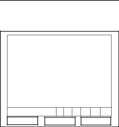
After the meter conducts all the self checks, the screen then appears similar to the one shown in Figure 2-4 below.
ABC.SIT |
2004/11/30 09:53 AM |
|
|
Velocity, ft/s |
Signal, dB |
0.00 |
32 |
|
|
|
|
|
|
|
|
|
|
Delta-T, ns |
Volume, l/s |
|
|
0.10 |
0.0 |
|
|
E0: No Errors
Figure 2-4: Screen After Powering On
2-8 |
Initial Setup |

April 2004
Powering On and Off (cont.)
To turn the PT878GC off, press the red key for 3 seconds. The screen now appears similar to Figure 2-5 below.
Velocity, ft/s |
Signal, dB |
SHUTDOWN: Meter OFF |
|
SLEEP: Meter Idle
CANCEL: Resume Operations
Delta-T, ns Volume, l/s
Shutdown |
|
Sleep |
|
Resume |
Figure 2-5: The Shutdown Menu
Three options are available:
•Press [F1] to shut down the PT878GC, turning it completely off.
•Press [F2] to send the PT878GC into sleep mode. In this mode, some of the power supplies shut down, but the PT878GC remains in a standby mode. Users can resume taking measurements immediately by pressing the power button.
•Press [F3] to cancel the command and return the PT878GC to normal operation.
If the PT878GC locks up, you can reset it by holding the power key (the red key in the upper right corner) for 15 seconds.
Initial Setup |
2-9 |
April 2004
Using the Screen and Keypad
The essential features for operating the TransPort are the screen and keypad. Although these features are common on portable instruments, the PT878GC design offers unique features to simplify and speed operation.
Screen
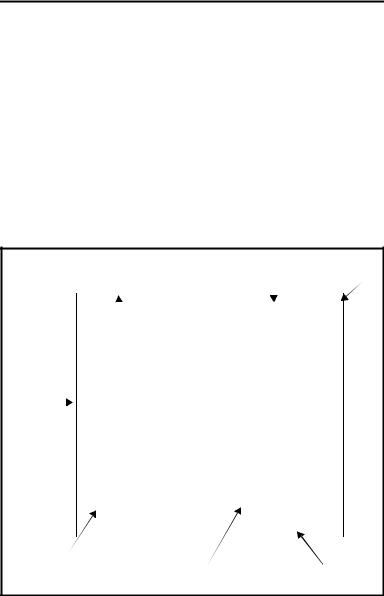
The primary function of the screen is to display information in order for you to accurately and easily take measurements. The TransPort screen consists of seven parts (see Figure 2-6 below).
Current |
Status Bar |
Battery |
||||
Site |
(alternates |
with |
Status |
|||
|
|
|
Menu Bar) |
|
|
|
|
|
|
|
|
|
|
|
|
DEFAULT |
2000/11/30 09:53 AM |
|
|
|
|
|
|
|
|
|
|
|
|
Velocity, ft/s |
Signal, dB |
|
||
|
|
|
||||
|
|
|
|
|
|
|
|
|
|
|
0.00 |
|
|
32 |
|
|
|
|
|
|||||
(Work |
|
|
|
|
|
|
|
|
|
|
|
|
|||||
|
|
|
|
|
|
|
|
|
|
|
|
|
|
||||
Area) |
|
|
|
|
|
|
|
|
|
|
|
|
|
|
|
|
|
|
|
|
|
|
|
|
|
|
|
|
|
|
|
|
|
||
Delta-T, ns |
|
|
Volume, l/s |
|
|||||||||||||
|
|
|
|
|
|
||||||||||||
|
|
|
|
0.10 |
|
|
0.0 |
|
|
||||||||
|
|
|
|
|
|
|
|
|
|
|
|
|
|
|
|
|
|
|
|
|
E0: No Errors |
|
|
|
|
|
|
|
|
|
|
|
|
||
|
|
|
|
|
|
|
|
|
|
|
|
|
|
|
|
|
|
|
|
|
|
|
|
|
|
|
|
|
|
|
|
|
|
|
|
Error Messages |
|
System |
|
|
Function Keys |
||||||||||||
|
|
|
|
|
Tray |
|
|
||||||||||
Figure 2-6: The PT878GC Screen in Operate Mode
The top line of the screen is the status bar, which normally displays the time, date and current site. However, when you press [MENU] (the menu key), the Menu Bar replaces the status bar.
2-10 |
Initial Setup |

April 2004
Screen (cont).
The middle of the screen is the work area, which displays the measured parameters, numeric measurements, and both bar and line graphs. (When you enter a selection on the Main Menu discussed in Chapter 4, Programming Site Data, this area displays menu prompts.) A line at the bottom of the area also displays error code messages, which are described in more detail in Chapter 10, Diagnostics and Troubleshooting.
The system tray, shown in Figure 2-6 on page 2-10, displays icons that indicate meter operations not otherwise shown. Table 2-3 below lists the icons and their meanings.
Table 2-3: Icons in the System Tray
Icon |
Function |
Meaning |
|
IR Transfer |
IR data transfer in progress. |
|
|
|
|
Alert |
Indicates the meter encoun- |
|
|
tered an error in operation. |
|
|
|
|
Log Running |
Indicates a log is running |
|
|
(marks). |
|
|
|
|
Log Pending |
Indicates a log is pending (no |
|
|
marks). |
|
|
|
|
Stopwatch |
Calibration Gate Operation: |
|
|
Watch is stopped when the |
|
|
gate is closed, or runs when it |
|
|
is open. (See page 3-46.) |
|
|
|
|
Snapshot |
Indicates that the Snapshot |
|
(To file) |
function has been activated, |
|
(To Printer) |
so users can take screen cap- |
|
tures (see page 6-23). |
|
|
|
|
|
|
|
The bottom of the screen displays the three feature key options: F1, F2 and F3. The feature keys have different functions, depending on the task you are performing.
Initial Setup |
2-11 |
April 2004
Keypad
The PT878GC keypad has 25 keys. The functions for each key are as follows (see Figure 2-7 on the next page):
•3 function keys ([F1], [F2], [F3]) — enable you to select the special functions which appear at the bottom of the screen.
•12 numeric keys (including - and .) — enable you to enter numeric data.
•4 arrow keys ([W ], [X], [S], [T]) — enable you to move through the menu options.
•[?] — Help key enables you to access on-line help.
•[MENU] — Menu key enables you to access the Menu Bar.
•[ENTER] — enables you to enter a particular menu, and enters selected values into the TransPort memory.
•[SEL] — enables you to move between data measurements on the screen.
•[ESC] — enables you to exit menus or menu options at any time; cancels numeric entry.
• Red key [ ] turns the power on or off, and toggles the backlight on or off.
2-12 |
Initial Setup |
Loading...