


 Loading...
PRODIGY
Service Manual
Part Number: LUN7396
Revision: C
This page left blank intentionally.
ii |
Prodigy Service Manual |
This document contains confidential or proprietary information of GE-Lunar Corp. neither the document nor the information is to be reproduced, distributed, used or disclosed, either in whole or in part, except as specifically authorized by GE-Lunar Corp.
GE-LUNAR Corporation makes no warranty of any kind with regard to this material, and shall not be held liable for errors contained herein or for incidental or consequential damages in connection with the furnishings or use of this manual.
Read through this manual thoroughly before attempting to service any components. Unauthorized service may void system warranties or service contracts. Consult the GE-LUNAR Customer Support Department prior to attempting any servicing:
608-828--2663
608-826-7107 (Fax)
gis a registered trademark of General Electric Company.
PRODIGY® is a trademark of GE-LUNAR Corporation.
Windows NT® is a trademark of Microsoft Corporation
Copyright© 2000 by GE-LUNAR Corporation.
Madison, Wisconsin. All rights reserved.
Prodigy Service Manual |
iii |
This page left blank intentionally.
iv |
Prodigy Service Manual |
READ THIS FIRST
Using This Manual:
A person who will be performing service work on the PRODIGY should use this manual in the following manner:
Read the Safety and Overview Chapters to familiarize yourself with the scanner as a whole and with the general function of the circuit boards.
Chapter 3 should be understood completely as it explains the Diagnostics Software (built in – requires a password for access).
The Chapter 4 and Chapter 5 contain common procedures and troubleshooting information and can be read as needed, but are good sources of information.
When a problem arises, Chapter 4 should be referenced. Check the table of contents for Chapter 4 to see if the problem being experienced is described. If so, refer to the appropriate page. If not, try to generalize the problem (e.g. the Detector is repeatedly running into the front of the scanner and reversing and then running back into the front of the scanner. This is a mechanical problem in general, specifically with Transverse Mechanics, check that subsection of Chapter 4 for the subsystem experiencing the fault.
This manual commonly references other Sections and pages of the manual as needed, so often procedures in the Chapter 5 Appendix are referred to as ways to solve problems described in Chapter 4.
Information Requested By GE-LUNAR:
When requesting assistance from GE-LUNAR, please provide the following information:
System Number (DF+xxxxx)
Institution or Doctor's name
Location
Complete list of symptoms
Names and part numbers of parts needed for service
Prodigy Service Manual |
v |
In addition to the information above, an Error Log printout and QA’s and QA history or other failing diagnostic test printout (Alignment Test etc.) will also help to improve the accuracy of our diagnosis:
For problems with specific patient scans, it is recommended that you copy the scan files to diskette, and send it, with a description of the problem, to the Applications Department at GE - LUNAR.
vi |
Prodigy Service Manual |

1 Safety
This chapter highlights safety devices and features a Service Engineer should know before servicing a PRODIGY system.
Chapter Contents:
1.0 General Safety . . . . . . . . . . . . . . . . . . . . . . . . . . . . . . . . . . . . . . . . . 1-15 1.1 Symbols and labels found on the PRODIGY . . . . . . . . . . . . . . . . . . 1-15 1.1.1 External Symbols. . . . . . . . . . . . . . . . . . . . . . . . . . . . . . . . . . . 1-15 1.1.2 Internal Symbols . . . . . . . . . . . . . . . . . . . . . . . . . . . . . . . . . . . 1-16 1.1.3 Labels . . . . . . . . . . . . . . . . . . . . . . . . . . . . . . . . . . . . . . . . . . . 1-16 1.2 Emergency Stop Button . . . . . . . . . . . . . . . . . . . . . . . . . . . . . . . . . . 1-19 1.3 Laser Exposure . . . . . . . . . . . . . . . . . . . . . . . . . . . . . . . . . . . . . . . . 1-20 1.4 Shutter Indicator . . . . . . . . . . . . . . . . . . . . . . . . . . . . . . . . . . . . . . . . 1-21 1.5 Cautions, Warnings, and Notes . . . . . . . . . . . . . . . . . . . . . . . . . . . . 1-21 1.5.1 Caution Statements . . . . . . . . . . . . . . . . . . . . . . . . . . . . . . . . . 1-21 1.5.2 Warning Statements . . . . . . . . . . . . . . . . . . . . . . . . . . . . . . . . 1-22 1.5.3 Note Statements . . . . . . . . . . . . . . . . . . . . . . . . . . . . . . . . . . . 1-22 1.6 Safety Concerns . . . . . . . . . . . . . . . . . . . . . . . . . . . . . . . . . . . . . . . . 1-22 1.6.1 Pinch points. . . . . . . . . . . . . . . . . . . . . . . . . . . . . . . . . . . . . . . 1-22 1.6.2 Laser safety. . . . . . . . . . . . . . . . . . . . . . . . . . . . . . . . . . . . . . . 1-23 1.6.3 Radiation safety. . . . . . . . . . . . . . . . . . . . . . . . . . . . . . . . . . . . 1-24 1.6.4 Scatter Radiation . . . . . . . . . . . . . . . . . . . . . . . . . . . . . . . . . . . 1-24 1.7 Controlling Computer and Accessories . . . . . . . . . . . . . . . . . . . . . . 1-26 1.7.1 Electrical Safety. . . . . . . . . . . . . . . . . . . . . . . . . . . . . . . . . . . . 1-26 1.7.3 Peripheral Configurations . . . . . . . . . . . . . . . . . . . . . . . . . . . . 1-26
1.7.4Standard room configuration (system no. DF+12000 and greater)1- 26
1.7.5Small room configuration (system no. DF+12000 and higher) 1-27
1.7.6Scanner power output configuration (system no. DF+11999 and
lower) . . . . . . . . . . . . . . . . . . . . . . . . . . . . . . . . . . . . . . . 1-27 1.7.7 Wall outlet configuration (system no. DF+11999 and lower) . . 1-27
Figure 1-1. The PRODIGY Display Panel . . . . . . . . . . . . . . . . . . . . . . . 1-19 Figure 1-2. Laser Warning Label (U.S. systems only) . . . . . . . . . . . . . . 1-20 Figure 1-4. Laser Warning Label (International systems only) . . . . . . . . 1-20 Figure 1-5. Source (x-rays) off - Shutter closed (green) . . . . . . . . . . . . . 1-21
PRODIGY Service Manual (Rev C - 2000) |
Safety113 |
Figure 1-6. Source (x-rays) on - Shutter open (yellow). . . . . . . . . . . . . . 1-21 Figure 1-7. Potential Pinch Points on the PRODIGY . . . . . . . . . . . . . . . 1-23 Figure 1-8. PRODIGY Iso-Dose Diagram . . . . . . . . . . . . . . . . . . . . . . . . 1-25
This document contains confidential or proprietary information of GE-Lunar Corp. Neither the document nor the information therein is to be reproduced, distributed, used or disclosed, either in whole or in part, except as specifically authorized by GE-Lunar Corp.
1-14 Safety |
PRODIGY Service Manual (Rev C - 2000) |

1.0General Safety
•DO NOT attempt to service the PRODIGY without first reading this manual.
•DO NOT attempt any repairs without prior instructions from authorized LUNAR personnel.
•In order to maintain electrical safety and electromagnetic compatibility, the Lunar PRODIGY is only to be connected to a computer, printer, and peripherals that are certified to be compliant with IEC 950/EN 60950 Safety of information technology equipment, including electrical business equipment and IEC 601-1-2 Medical electrical equipment, Part 1: General requirements for safety, 2. Collateral Standard: Electromagnetic compatibility - Requirements and tests.Emergency Stop Button
1.1Symbols and labels found on the PRODIGY
1.1.1External Symbols
•The following symbols are found on the PRODIGY, in the Operators manual, and in the Service Manual.
Attention: contains important safety information such as the location of a pinch point.
Emergency Stop Button: shows the location of the emergency stop button.
Power On: shows the location of the Power On indicator and the switch position for Power On.
Power Off: shows the switch position for Power Off.
Laser On: shows the location of the Laser On indicator. It is found only on systems delivered internationally.
This document contains confidential or proprietary information of GE-Lunar Corp. Neither the document nor the information therein is to be reproduced, distributed, used or disclosed, either in whole or in part, except as specifically authorized by GE-Lunar Corp.
PRODIGY Service Manual (Rev C - 2000) |
Safety1-15 |

Shutter Open: shows the location of the Shutter Open indicator.
X-ray On: shows the location of the X-Ray On indicator.
Type B Equipment: shows that the scanner has Type B protection against electrical shock.
1.1.2Internal Symbols
•The following symbols are found inside the PRODIGY, and in the Service Manual.
Protective Earth: shows the location of a Protective Earth
Terminal.
Functional Earth: shows the location of a Functional Earth
Terminal.
1.1.3Labels
•The following labels are found on the PRODIGY Scanner.
Laser Caution Label: Shows that the scanner uses a Class II laser. This label is not found on systems shipped to Canada.
Laser Caution Label: Canada only
This document contains confidential or proprietary information of GE-Lunar Corp. Neither the document nor the information therein is to be reproduced, distributed, used or disclosed, either in whole or in part, except as specifically authorized by GE-Lunar Corp.
1-16 Safety |
PRODIGY Service Manual (Rev C - 2000) |
Tube Head Assembly Label (system number DF+12000 and greater): This label gives tube head assembly and x-ray source characteristics information. It is located on the tube head assembly and the foot panel of the scanner.
Tube Head Assembly Label (system number DF+11999 and lower): This label gives tube head assembly and x-ray source characteristics information. It is located on the tube head assembly and the foot panel of the scanner.
A definition of each symbol on this label follows:
Inherent Filtration
Tube Insert
X-ray Source
Focal Point
System Label (system number DF+12000 and greater): This label gives system input power requirements and compliance information. It is located on the foot panel of scanners. The CE mark shows compliance with UL/CSA and the Medical Device Directive 93/42/EEC.
System Label (system number DF+11999 and lower): This label gives system input power requirements and compliance information. It is located on the foot panel of scanners. The CE mark shows compliance with UL/CSA and the Medical Device Directive 93/42/EEC.
This document contains confidential or proprietary information of GE-Lunar Corp. Neither the document nor the information therein is to be reproduced, distributed, used or disclosed, either in whole or in part, except as specifically authorized by GE-Lunar Corp.
PRODIGY Service Manual (Rev C - 2000) |
Safety1-17 |

High Voltage Power Supply: This label gives high voltage power supply (x-ray generator) information. It is located on the positive and negative power supplies, and foot panel of the scanner.
X-ray Controller: This label shows x-ray controller compliance. It is located on the foot panel of the scanner.
Collimator Assembly: This label gives collimator assembly information. It is located on the collimator and foot panel of the scanner.
Warning Label and Radiation Symbol: The Warning label shows that the system uses ionizing radiation. It is found only on systems delivered in the United States. Always obey instructions for safe operation.
Radiation Label: This label shows that the system uses ionizing radiation.
Grounding Reliability Label: This label states that grounding reliability can only be maintained when using a “Hospital Grade” or “Hospital Only” receptacle. It is only found on systems delivered in the United States.
This document contains confidential or proprietary information of GE-Lunar Corp. Neither the document nor the information therein is to be reproduced, distributed, used or disclosed, either in whole or in part, except as specifically authorized by GE-Lunar Corp.
1-18 Safety |
PRODIGY Service Manual (Rev C - 2000) |

1.2Emergency Stop Button
•The Emergency Stop Button is a round red button located on the scanner display panel (see Figure 1-1). When pressed, power is removed from the X-ray tube head, the laser, and the shutter is closed. Power is also removed from the scan arm motors, allowing the operator/patient to push the scan arm out of the way.
Figure 1-1. The PRODIGY Display Panel
This document contains confidential or proprietary information of GE-Lunar Corp. Neither the document nor the information therein is to be reproduced, distributed, used or disclosed, either in whole or in part, except as specifically authorized by GE-Lunar Corp.
PRODIGY Service Manual (Rev C - 2000) |
Safety1-19 |

1.3Laser Exposure
•The PRODIGY is equipped with a Class II Laser device. This laser is used for patient positioning. A Class II rating indicates a low power visible laser that is not normally hazardous to eyesight but has the potential to be hazardous if viewed directly for an extended period of time. Because of this potential hazard, DO NOT stare directly into the beam while the laser is in operation, and DO NOT allow the beam to shine directly into the patients' eyes. No specific eye protection is required with a Class II laser.
•A amber laser-on indicator, located on the front of the scan arm, is lit when the laser is on. The program activates the laser during positioning for an image acquisition. The program then turns off the laser when you begin the scan. The emergency stop button will turn off the laser.
•There is a caution label (Figure 1.2) on the scan arm near the Display Panel.
Figure 1-2. Laser Warning Label (U.S. systems only)
Figure 1-3. Laser Warning Label (Canadian Systems only)
Figure 1-4. Laser Warning Label (International systems only)
Note: DO NOT STARE INTO THE BEAM while the laser is operating.
This document contains confidential or proprietary information of GE-Lunar Corp. Neither the document nor the information therein is to be reproduced, distributed, used or disclosed, either in whole or in part, except as specifically authorized by GE-Lunar Corp.
1-20 Safety |
PRODIGY Service Manual (Rev C - 2000) |
1.4Shutter Indicator
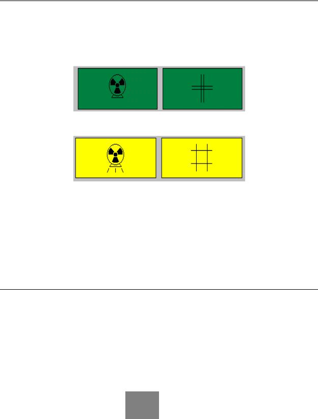
•This symbol is used to indicate an open-shutter condition in accordance with the safety standards established by the International Electrotechnical Commission (IEC).
Figure 1-5. Source (x-rays) off - Shutter closed (green)
Figure 1-6. Source (x-rays) on - Shutter open (yellow)
•This symbol appears near the yellow X-ray shutter-open indicator light. The X-ray shutter-open indicator light is located on the Display Panel on the scan arm near the front.
Note: When the x-ray on / shutter open symbol appears in literature associated with the PRODIGY scanner, it will be used to indicate that the procedure being described results in an openshutter condition. During these times personnel should exercise caution to avoid excessive exposure to the X-rays.
1.5Cautions, Warnings, and Notes
•This manual contains warning and caution statements wherever appropriate for your safety. The warnings and cautions used throughout the manual are based on the safety standards established by the International Electrotechnical Commission (IEC). In addition, the manual uses notes to attract the reader's attention to important information.
1.5.1Caution Statements
A caution statement reflects a condition that, if not avoided, could cause equipment or property damage.
This document contains confidential or proprietary information of GE-Lunar Corp. Neither the document nor the information therein is to be reproduced, distributed, used or disclosed, either in whole or in part, except as specifically authorized by GE-Lunar Corp.
PRODIGY Service Manual (Rev C - 2000) |
Safety1-21 |

1.5.2 Warning Statements
A warning statement reflects a potentially hazardous condition that, if not avoided, could result in serious injury.
1.5.3 Note Statements
Note: This symbol turns the reader's attention to important information which may otherwise be overlooked.
1.6Safety Concerns
1.6.1Pinch points
The Warning label below identifies the location of possible pinch points
Because the PRODIGY Densitometer contains moving parts, there are places on the scanner where there is a danger of pinching. Operators should be aware of these pinch points to avoid injury to
the patient or themselves. When the scanner arm is in motion, make sure possible pinch point locations are clear at all times. Labels applied at the LUNAR factory indicate the location of the pinch points. The pinch points and their labels are shown in the figure 1-7.
This document contains confidential or proprietary information of GE-Lunar Corp. Neither the document nor the information therein is to be reproduced, distributed, used or disclosed, either in whole or in part, except as specifically authorized by GE-Lunar Corp.
1-22 Safety |
PRODIGY Service Manual (Rev C - 2000) |
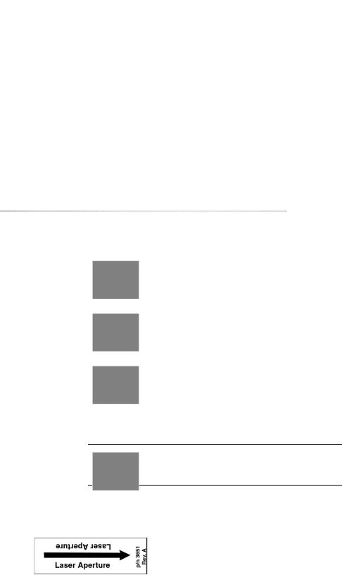
Figure 1-7. Potential Pinch Points on the PRODIGY
Do not touch the AC Surge Suppressor (located on the AC terminal block) it may be hot.
Do not electrically connect the isolation transformer bolt head to ground, doing this will short out the transformer
Scan table isolated outlet strip must be appropriately connected.
1.6.2 Laser safety
DO NOT STARE INTO THE LASER BEAM during patient positioning and Quality Assurance procedures.
The label that follows is located on the scanner arm and shows the location of the laser aperture.
This document contains confidential or proprietary information of GE-Lunar Corp. Neither the document nor the information therein is to be reproduced, distributed, used or disclosed, either in whole or in part, except as specifically authorized by GE-Lunar Corp.
PRODIGY Service Manual (Rev C - 2000) |
Safety1-23 |
1.6.3 Radiation safety
X-ray exposure: The system makes radiation when electric voltage is supplied to, and current flows through, the x-ray tube. During a measurement, the shutter opens to let a beam of radiation pass through the scanner table and patient. The radiation field at the table top is 19.2 mm x 3.3 mm. Lead oxide shielding surrounds the x-ray tube insert inside the tube housing assembly and reduces radiation levels around the scanner table.
Skin entrance dose: Table 1 of the PRODIGY Operators Safety and Specifications manual shows irradiation times and skin entrance doses.
1.6.4Scatter Radiation
•There is some scatter radiation from the PRODIGY when it is running. Figure 1-8 shows the radiation dosages while the scanner is running at 3.00 mA at certain distances.
•These dosages are relatively insignificant as the allowed yearly dosage for a person working with radiation emitting equipment is 5000 mRem. Radiation however should be avoided when possible.
This document contains confidential or proprietary information of GE-Lunar Corp. Neither the document nor the information therein is to be reproduced, distributed, used or disclosed, either in whole or in part, except as specifically authorized by GE-Lunar Corp.
1-24 Safety |
PRODIGY Service Manual (Rev C - 2000) |

Figure 1-8. PRODIGY Iso-Dose Diagram
This document contains confidential or proprietary information of GE-Lunar Corp. Neither the document nor the information therein is to be reproduced, distributed, used or disclosed, either in whole or in part, except as specifically authorized by GE-Lunar Corp.
PRODIGY Service Manual (Rev C - 2000) |
Safety1-25 |

1.7Controlling Computer and Accessories
1.7.1Electrical Safety
IEC and UL/CSA certification
IEC: To maintain electrical safety, all computer equipment and accessories connected to the scanner must meet all IEC requirements for safety, such as IEC 950, "Safety of information technology equipment, including electrical business equipment," and IEC 801-5, "EMC Surge Immunity Requirements." The computer and all accessories must have the CE label.
UL/CSA: To maintain electrical safety, all computer equipment and accessories connected to the scanner must have safety agency approvals for UL/CSA.
1.7.2 Electromagnetic interference
Although the scanner meets safety standards regarding electromagnetic interference (EN60601-1-2), you may still experience a loss of performance under extreme electromagnetic conditions. Maximize the distance between the scanner and other equipment, and use a dedicated power line, to avoid interference to and from the scanner.
1.7.3 Peripheral Configurations
The correct connection of the computer and all peripherals is necessary to maintain electrical safety. The signal cable of the scanner is intended only for connection to an approved computer. Call LUNAR Support or your LUNAR
distributor before adding peripherals.
Note: The scanner's output power strip can be used to supply the Host PC with isolated power. If it is to be used the following conditions must be met. If the conditions cannot be met, the scanner's output power strip cannot be used.
Note: See also Peripheral Block Diagrams - Section 2.2.3
1.7.4 Standard room configuration (system no. DF+12000 and greater)
The computer, peripherals, and all other equipment must be located more than 1.83 m from the scanner. Use an outlet strip to power the computer and all peripherals. The outlet strip must be mounted off the floor so that it does not touch other equipment. If your outlet strip was provided by LUNAR, it has a maximum output of 15A, 120VAC. Only system-related equipment should be powered by the outlet strip.
This document contains confidential or proprietary information of GE-Lunar Corp. Neither the document nor the information therein is to be reproduced, distributed, used or disclosed, either in whole or in part, except as specifically authorized by GE-Lunar Corp.
1-26 Safety |
PRODIGY Service Manual (Rev C - 2000) |
A modem and/or network connection can be made at any time if you are using the standard room configuration.
1.7.5 Small room configuration (system no. DF+12000 and higher)
You must power the computer, peripherals, and all other equipment with an isolating transformer if the room is too small to maintain at least 1.83 m of separation between the scanner and all other equipment.
The isolation transformer supplied by LUNAR has a maximum output of 400/ 500VA. Only system-related equipment should be powered by the isolation transformer. Failure to use an isolation transformer can cause leakage currents in excess of 100 microamperes.
A modem and/or network connection can only be made in the small room configuration if all exposed metal surfaces of the computer and peripherals are out of the patient environment.
1.7.6 Scanner power output configuration (system no. DF+11999 and lower)
LUNAR recommends that you use scanner power output to provide isolated power to the computer and all peripherals. The power strip must be mounted off the floor such that it does not touch other equipment. The computer and ALL peripherals must be powered by the scanner. All other equipment must not be powered by the scanner and must be located more than 1.83 m from the scanner. Failure to use scanner power output can cause leakage currents in excess of 100 microamperes.
If a network and/or modem connection is needed, refer to the wall outlet configuration.
1.7.7 Wall outlet configuration (system no. DF+11999 and lower)
As an option to scanner power output, a wall outlet can be used to power the computer and peripherals. Isolated power from the scanner must not be used to power any equipment if a wall outlet is used. All exposed metal surfaces of the computer, peripherals, and other equipment must be located more than 1.83 m from the scanner.
A network and/or modem connection can be made to the computer if power is supplied from a wall outlet as described above.
This document contains confidential or proprietary information of GE-Lunar Corp. Neither the document nor the information therein is to be reproduced, distributed, used or disclosed, either in whole or in part, except as specifically authorized by GE-Lunar Corp.
PRODIGY Service Manual (Rev C - 2000) |
Safety1-27 |
This page left blank intentionally.
This document contains confidential or proprietary information of GE-Lunar Corp. Neither the document nor the information therein is to be reproduced, distributed, used or disclosed, either in whole or in part, except as specifically authorized by GE-Lunar Corp.
1-28 Safety |
PRODIGY Service Manual (Rev C - 2000) |
2 |
System Overview |
This chapter provides an overview of the PRODIGY system.
•In addition the chapter contains a brief discussion of major subsystems and illustrations of the PRODIGY power system.
•This Chapter contains the PRODIGY Block Diagrams
2.0 PRODIGY System . . . . . . . . . . . . . . . . . . . . . . . . . . . . . . . . . . . . . . 1-33 2.0.1 PRODIGY Electronics . . . . . . . . . . . . . . . . . . . . . . . . . . . . 1-33 2.1 Electronics . . . . . . . . . . . . . . . . . . . . . . . . . . . . . . . . . . . . . . . . . . . . 1-35 2.1.1 Cautions . . . . . . . . . . . . . . . . . . . . . . . . . . . . . . . . . . . . . . 1-35 2.1.2 Electronics Pan . . . . . . . . . . . . . . . . . . . . . . . . . . . . . . . . . 1-35 2.1.3 Scan Arm. . . . . . . . . . . . . . . . . . . . . . . . . . . . . . . . . . . . . . 1-36 2.1.4 Power specifications . . . . . . . . . . . . . . . . . . . . . . . . . . . . . 1-36
2.2 PRODIGY Block Diagrams . . . . . . . . . . . . . . . . . . . . . . . . . . . . . . . . 1-38
2.2.1 PRODIGY I (System numbers DF+11999 and lower) Power Distribution Block Diagram (AC entrance) . . . . . . . . . . . . . . . . . 1-38
2.2.2 PRODIGY System Block Diagram PRODIGY I System Block Diagram . . . . . . . . . . . . . . . . . . . . . . . . . . . . . . . . . . . . . . . . . . . 1-39
2.2.3 PRODIGY I Peripheral Configuration Block Diagrams . . . 1-40 2.2.4 PRODIGY II System / Power Block Diagram . . . . . . . . . . 1-41 2.3 PRODIGY Fusing . . . . . . . . . . . . . . . . . . . . . . . . . . . . . . . . . . . . . . . 1-42
2.4 PRODIGY I (system numbers DF+11999 and lower) Single Board Controller . . . . . . . . . . . . . . . . . . . . . . . . . . . . . . . . . . . . . . . . . . . . . . . . 1-43
2.4.1 SBC Functions . . . . . . . . . . . . . . . . . . . . . . . . . . . . . . . . . 1-43 2.4.2 SBC Reset. . . . . . . . . . . . . . . . . . . . . . . . . . . . . . . . . . . . . 1-43 2.4.3 SBC / Host PC Interface . . . . . . . . . . . . . . . . . . . . . . . . . . 1-44
2.5 PRODIGY II Combined Single Board Controller (cSBC) (systems DF+12000 and greater) . . . . . . . . . . . . . . . . . . . . . . . . . . . . . . . . . . . . . 1-45
2.5.1 cSBC System Architecture . . . . . . . . . . . . . . . . . . . . . . . . . . . 1-45 2.5.2 cSBC Functions. . . . . . . . . . . . . . . . . . . . . . . . . . . . . . . . . . . . 1-46 2.5.3 TRANS / LONG MOTOR Control and Status . . . . . . . . . . . . . 1-50 2.5.4 AGS ROLL . . . . . . . . . . . . . . . . . . . . . . . . . . . . . . . . . . . . . . . 1-51 2.5.5 AGS DAC . . . . . . . . . . . . . . . . . . . . . . . . . . . . . . . . . . . . . . . . 1-51 2.5.6 SCANNER RESET . . . . . . . . . . . . . . . . . . . . . . . . . . . . . . . . . 1-52 2.5.7 GE-LUNAR Model 7861 X-ray Generator Errors. . . . . . . . . . . 1-53 2.5.8 DC FAIL. . . . . . . . . . . . . . . . . . . . . . . . . . . . . . . . . . . . . . . . . . 1-54
PRODIGY Service Manual (Rev C - 2000) |
System Overview229 |
2.5.9 DCA / AGS / BIAS DAC's . . . . . . . . . . . . . . . . . . . . . . . . . . . . 1-54 2.5.10 KV/mA DAC . . . . . . . . . . . . . . . . . . . . . . . . . . . . . . . . . . . . . . 1-55 2.5.11 ARC/FIL DAC. . . . . . . . . . . . . . . . . . . . . . . . . . . . . . . . . . . . . 1-55 2.5.12 PEAK DAC. . . . . . . . . . . . . . . . . . . . . . . . . . . . . . . . . . . . . . . 1-55 2.5.13 MAX PLD Peripherals . . . . . . . . . . . . . . . . . . . . . . . . . . . . . . 1-55 2.5.14 Interrupts . . . . . . . . . . . . . . . . . . . . . . . . . . . . . . . . . . . . . . . . 1-56 2.5.15 MASTER RESET. . . . . . . . . . . . . . . . . . . . . . . . . . . . . . . . . . 1-56 2.5.16 SUICIDE RESET . . . . . . . . . . . . . . . . . . . . . . . . . . . . . . . . . . 1-57 2.5.17 MISC OUT . . . . . . . . . . . . . . . . . . . . . . . . . . . . . . . . . . . . . . . 1-57 2.5.18 MISC IN . . . . . . . . . . . . . . . . . . . . . . . . . . . . . . . . . . . . . . . . . 1-57 2.5.19 Stepper Motor Control . . . . . . . . . . . . . . . . . . . . . . . . . . . . . . 1-58 2.5.20 OMI Input . . . . . . . . . . . . . . . . . . . . . . . . . . . . . . . . . . . . . . . . 1-59 2.5.21 Patient Positioners. . . . . . . . . . . . . . . . . . . . . . . . . . . . . . . . . 1-59 2.5.22 Limit Switches . . . . . . . . . . . . . . . . . . . . . . . . . . . . . . . . . . . . 1-59 2.5.23 X-ray Source Control / Mechanical Interlocks . . . . . . . . . . . . 1-59 2.5.24 Shutter / Collimator Drive. . . . . . . . . . . . . . . . . . . . . . . . . . . . 1-60 2.5.25 End of Exposure Alarm . . . . . . . . . . . . . . . . . . . . . . . . . . . . . 1-60 2.5.26 Panel LED's . . . . . . . . . . . . . . . . . . . . . . . . . . . . . . . . . . . . . . 1-60 2.5.27 HVPS Control . . . . . . . . . . . . . . . . . . . . . . . . . . . . . . . . . . . . 1-60 2.5.28 ADC . . . . . . . . . . . . . . . . . . . . . . . . . . . . . . . . . . . . . . . . . . . . 1-61 2.5.29 mA Low Range . . . . . . . . . . . . . . . . . . . . . . . . . . . . . . . . . . . 1-61 2.5.30 Detector Interface . . . . . . . . . . . . . . . . . . . . . . . . . . . . . . . . . 1-61 2.5.31 Communications Ports. . . . . . . . . . . . . . . . . . . . . . . . . . . . . . 1-62 2.5.32 Debug RS-232 Port . . . . . . . . . . . . . . . . . . . . . . . . . . . . . . . . 1-62 2.5.33 Diagnostic LED's . . . . . . . . . . . . . . . . . . . . . . . . . . . . . . . . . . 1-62
2.6 Power Distribution (PRODIGY II Systems DF+1200 and greater) . . 1-64 2.7 Tube Head and X-ray Insert . . . . . . . . . . . . . . . . . . . . . . . . . . . . . . . 1-65 2.7.1 X-ray generation and Spectrum. . . . . . . . . . . . . . . . . . . . . 1-65 2.8 X-ray Generator (High Voltage Power Supply(ies)) . . . . . . . . . . . . . 1-66
2.9 MAX Board (PRODIGY I systems DF+11999 and lower only) . . . . . 1-67 2.9.1 MAX Board Function . . . . . . . . . . . . . . . . . . . . . . . . . . . . . 1-67 2.9.2 Dedicated +28VDC power supply . . . . . . . . . . . . . . . . . . . 1-67
2.10 XORB Board (PRODIGY I Systems DF+11999 and lower only). . . 1-68 2.11 Detector Sub System . . . . . . . . . . . . . . . . . . . . . . . . . . . . . . . . . . . 1-69 2.11.1 Detector Overview . . . . . . . . . . . . . . . . . . . . . . . . . . . . . . 1-69 2.11.2 Detector Operation. . . . . . . . . . . . . . . . . . . . . . . . . . . . . . 1-69 2.11.3 Detector Daughter Board Overview . . . . . . . . . . . . . . . . . 1-70 2.11.4 Detector Daughter Board Operation . . . . . . . . . . . . . . . . 1-71 2.11.5 Detector Mother Board Overview. . . . . . . . . . . . . . . . . . . 1-72 2.11.6 Detector Mother Board Operation . . . . . . . . . . . . . . . . . . 1-72
2.12 FOINK (PRODIGY I Systems DF+11999 and lower only) . . . . . . . 1-74 2.12.1 FOINK Functions . . . . . . . . . . . . . . . . . . . . . . . . . . . . . . . 1-74 2.12.2 Motion Control and Detection . . . . . . . . . . . . . . . . . . . . . 1-74
2.13 Display Panel . . . . . . . . . . . . . . . . . . . . . . . . . . . . . . . . . . . . . . . . . 1-75 2.14 Audible X-RAY OFF Signal . . . . . . . . . . . . . . . . . . . . . . . . . . . . . . . 1-77
This document contains confidential or proprietary information of GE-Lunar Corp. Neither the document nor the information therein is to be reproduced, distributed, used or disclosed, either in whole or in part, except as specifically authorized by GE-Lunar Corp.
2-30 System Overview |
PRODIGY Service Manual (Rev C - 2000) |
2.15 X-Ray Collimator Subsystem . . . . . . . . . . . . . . . . . . . . . . . . . . . . . 1-78 2.16 PRODIGY Specifications . . . . . . . . . . . . . . . . . . . . . . . . . . . . . . . . 1-79 2.16.1 Component specifications . . . . . . . . . . . . . . . . . . . . . . . . 1-79 2.16.2 Functional specifications . . . . . . . . . . . . . . . . . . . . . . . . . 1-79 2.16.3 Maximum scan area (long x transverse) . . . . . . . . . . . . . 1-79 2.16.4 Programs. . . . . . . . . . . . . . . . . . . . . . . . . . . . . . . . . . . . . 1-80 2.16.5 Environmental specifications. . . . . . . . . . . . . . . . . . . . . . 1-80 2.16.6 Storage and transport environment. . . . . . . . . . . . . . . . . 1-81 2.16.7 X-ray generator (system no. DF+12000 and higher). . . . 1-81 2.16.8 X-ray generator (system no. DF+11999 and lower) . . . . 1-83 2.16.9 GE-LUNAR 8022 x-ray tube . . . . . . . . . . . . . . . . . . . . . . 1-85
2.16.10 GE-LUNAR 8743 x-ray tube head assembly (system no. DF+12000 and higher) . . . . . . . . . . . . . . . . . . . . . . . . . . . . . . . . 1-86
2.16.11 LUNAR 6838 x-ray tube head assembly (system no. DF+11999 and lower). . . . . . . . . . . . . . . . . . . . . . . . . . . . . . . . . 1-87
2.16.12 Laser specifications. . . . . . . . . . . . . . . . . . . . . . . . . . . . 1-88 2.16.13 Compatible components . . . . . . . . . . . . . . . . . . . . . . . . 1-89 2.16.14 FDA Certified Components (USA Only) . . . . . . . . . . . . 1-89 2.17 Secondary Calibration / Daily QA . . . . . . . . . . . . . . . . . . . . . . . . . . 1-91 2.17.1 Secondary Calibration overview . . . . . . . . . . . . . . . . . . . 1-91 2.17.2 Starting the Daily QA (secondary calibration) . . . . . . . . . 1-91 Peak Test. . . . . . . . . . . . . . . . . . . . . . . . . . . . . . . . . . . . . . . . . . 1-92 2.17.3 Tests Performed in the Secondary Calibration . . . . . . . . 1-92 2.17.4 QA Database. . . . . . . . . . . . . . . . . . . . . . . . . . . . . . . . . . 1-94
Figure 2-9. PRODIGY System Exploded View of External Covers and associated hardware . . . . . . . . . . . . . . . . . . . . . . . . . . . . . . . . . . . . . . . 1-33
Figure 2-10. PRODIGY I NTC thermistor on the Primary Terminal Block1-35 Figure 2-11. PRODIGY I Power Distribution Block Diagram . . . . . . . . . 1-38 Figure 2-12. PRODIGY I (systems DF+11999 and lower) Block Diagram1-39
Figure 2-13. PRODIGY I (Systems DF+11999 and lower) Peripheral Configuration Block Diagrams . . . . . . . . . . . . . . . . . . . . . . . . . . . . . . . . 1-40
Figure 2-14. PRODIGY II System / Power Block Diagram . . . . . . . . . . . 1-41 Figure 2-15. Detector Block Diagram . . . . . . . . . . . . . . . . . . . . . . . . . . . 1-69 Figure 2-16. Detector Daughter Board Operation . . . . . . . . . . . . . . . . . 1-71 Figure 2-17. PRODIGY Detector Module . . . . . . . . . . . . . . . . . . . . . . . . 1-73 Figure 2-18. PRODIGY display panel. . . . . . . . . . . . . . . . . . . . . . . . . . . 1-75 Figure 2-19. Reference axis and target angles for tube head assembly 1-85 Figure 2-20. Anode heating/cooling curves . . . . . . . . . . . . . . . . . . . . . . 1-86 Figure 2-21. Cathode emission characteristics . . . . . . . . . . . . . . . . . . . 1-88 Figure 2-22. X-ray tube assembly heating/cooling curves . . . . . . . . . . . 1-88 Figure 2-23. PRODIGY Daily QA printout with expected values . . . . . . 1-95
Table 2-1. PRODIGY I (Systems DF+11999 and lower) Fuses . . . . . . . 1-42 Table 2-2. PRODIGY II (systems DF+12000 and greater) Fuses. . . . . . 1-42 Table 2-3. PRODIGY Component Specifications . . . . . . . . . . . . . . . . . . 1-79
This document contains confidential or proprietary information of GE-Lunar Corp. Neither the document nor the information therein is to be reproduced, distributed, used or disclosed, either in whole or in part, except as specifically authorized by GE-Lunar Corp.
PRODIGY Service Manual (Rev C - 2000) |
System Overview 2-31 |
Table 2-4. X-ray generator technical information. . . . . . . . . . . . . . . . . . . 1-81 Table 2-5. Table 4. X-ray generator technical information. . . . . . . . . . . . 1-83 Table 2-6. LUNAR 8022 X-ray tube technical information. . . . . . . . . . . . 1-85 Table 2-7. LUNAR 8743 x-ray tube assembly technical information. . . . 1-86 Table 2-8. LUNAR 6838 x-ray tube assembly technical information. . . . 1-87 Table 2-9. Laser specifications.. . . . . . . . . . . . . . . . . . . . . . . . . . . . . . . . 1-88
Table 2-10. FDA certified components (system no. DF+12000 and higher).1- 89
Table 2-11. FDA certified components (system no. DF+11999 and lower).1-90
This document contains confidential or proprietary information of GE-Lunar Corp. Neither the document nor the information therein is to be reproduced, distributed, used or disclosed, either in whole or in part, except as specifically authorized by GE-Lunar Corp.
2-32 System Overview |
PRODIGY Service Manual (Rev C - 2000) |

2.0PRODIGY System
The PRODIGY includes the patient table and frame, X-ray tube, X-ray generator, detector, and arm. Its physical specifications are summarized in section 2.15.
The PRODIGY has a mechanical design with two separate motion systems that are capable of simultaneous operation. These are transverse, and longitudinal. Both motion systems are driven by stepper motors.
2.0.1 PRODIGY Electronics
The internal components of the scanner are safely secured by a number of panels, including the scanner's tabletop.
Figure 2-9. PRODIGY System Exploded View of External Covers and associated hardware
•The front and side panels are secured by screws from the inside.
•The rear panel is secured by screws from the outside.
•The table top is screwed down from the top.
Note: Primary Service access to the electronics of the scanner is through the table top.
This document contains confidential or proprietary information of GE-Lunar Corp. Neither the document nor the information therein is to be reproduced, distributed, used or disclosed, either in whole or in part, except as specifically authorized by GE-Lunar Corp.
PRODIGY Service Manual (Rev C - 2000) |
System Overview 2-33 |
•The Detector electronics (in the scan arm) are secured by an upper and lower shroud, held in place by screws.
•Each metal panel is grounded to the electronics pan.
It is not usually necessary to remove the front and back panels for most service needs. However, if access is needed to the Front and Rear Longitudinal Carriages, these can be removed.
The back panel is secured by hex socket head-head screws and must be slid out of the way, for it is between the Arm Column and the frame.
If access is needed to the detector, Transverse Limit Switches or the other components mounted above in the arm, the covers of the arm must be removed.
•The upper scan arm shroud can be removed by loosening the two screws holding it in place (on the back of the arm column) and tipping it forward.
•The lower cover is held in place by four screws, two in the front and two in the back, be sure to remove the ground wire for the metal portion of the lower cover as well
This document contains confidential or proprietary information of GE-Lunar Corp. Neither the document nor the information therein is to be reproduced, distributed, used or disclosed, either in whole or in part, except as specifically authorized by GE-Lunar Corp.
2-34 System Overview |
PRODIGY Service Manual (Rev C - 2000) |

2.1Electronics
2.1.1Cautions
PRODIGY electronics are static sensitive, take static control precautions before servicing scanner circuitry.
PRODIGY I electronics use Negative Temperature Coefficient (NTC) thermistors to limit the in rush current of the AC isolation transformer and the Detector Mother Board. These devices have a high resistance when cold and decrease in resistance when warm.
Figure 2-10. PRODIGY I NTC thermistor on the Primary Terminal Block
•A cool down period of 30 seconds is required before power is turned on on the system.
PRODIGY I ONLY: Failure to allow the system to “cool down” may cause the circuit breaker for the AC line to trip and / or the + 12VDC for the Detector Mother Board (DMB) will not come up to +12 VDC.
Note: The error log entry "DMB Power Cycle observed" is an indicator that the DC power to the Detector Mother Board has been interrupted and the system should be powered down for 30 seconds to restore power to the Detector Mother Board.
PRODIGY I ONLY: The NTC’s can get hot - they are located on the AC terminal block and on the DC terminal block be careful when servicing these areas of the scanner.
2.1.2 Electronics Pan
This document contains confidential or proprietary information of GE-Lunar Corp. Neither the document nor the information therein is to be reproduced, distributed, used or disclosed, either in whole or in part, except as specifically authorized by GE-Lunar Corp.
PRODIGY Service Manual (Rev C - 2000) |
System Overview 2-35 |
The electronic components of the PRODIGY are mounted on the grounded Electronics Pan which is horizontally fastened inside the frame.
Note: Appendix 2 A contains a layout drawing of the Electronics Pan for PRODIGY I and PRODIGY II systems.
PRODIGY I Systems (System numbers DF+11999 and lower):
•There are four low-voltage linear DC power supplies (under 30VDC), and two high-voltage DC power supplies (to supply 76kV to the x-ray tube) on the pan.
•In addition to the power supplies, the electronics mounting chassis holds four printed circuit boards, a stepper motor controller, the audible alarm, an AC entrance/line filter/fuse holder, an isolation transformer and a terminal strip for AC power distribution to the Host PC and peripherals.
PRODIGY II Systems (System numbers DF+12000 and greater):
•There is one low-voltage DC switching power supply (under 30VDC), and one high-voltage DC power supply (x-ray generator - supplies 76kV to the x-ray tube) on the pan.
•In addition to the power supplies, the electronics mounting chassis holds one printed circuit board, a stepper motor controller, and an AC entrance/ line filter/fuse holder.
2.1.3Scan Arm
•The scan arm contains one high-voltage power supply (1000VDC / +12 VDC input) is located in the upper arm near the X-ray detector and provides power to the Detector Array.
•The scan arm also houses the detector and 5 associated printed circuit boards, and a stepper motor contoller.
2.1.4Power specifications
Leakage current
•Total System with Isolation Transformer: <100 microamperes.
•Scanner Table alone: <100 microamperes.
Scanner input power
•PRODIGY I ONLY: The scanner has 12 different nominal inputs: 100, 110, 115, 120, 125, 127, 200, 220, 230, 240, 250, and 254 VAC. During installation, the scanner is configured for the nominal input which best matches the voltage on site.
This document contains confidential or proprietary information of GE-Lunar Corp. Neither the document nor the information therein is to be reproduced, distributed, used or disclosed, either in whole or in part, except as specifically authorized by GE-Lunar Corp.
2-36 System Overview |
PRODIGY Service Manual (Rev C - 2000) |
Loading...