


PTS25SHSARSS
GE PTS25SHSARSS, PTS25SHRCRBS, PTS25SHPARBS, PTS25LHSARWW, PTS25LHSARCC Owner’s Manual
...
N
vvvvw.GEAppliances.com
Safety Instn_ions
Adapter Plugs .................... 3
(?onnect Electficiw ................ 3
Extension Cords .................. 2
Proper Disposal ................... 2
Safetv Precautions ................. 2
Operating Instru_Ttions
Additional Features ................ 9
Aurora atic Icemaker . ............. ] 0
(kgntrols ...................... 4, 5
Crispers and Pans .............. 9, 10
Sheh'es and Bins ................ 7, 8
VVamr Dispenser ................. 11
_4'ater Filter ...................... 6
Models 22,25
Cong_lateur sup&'ieur
Rdfrigdrateurs
La section frangaise commence a la page 31
Care and Cleaning .............. 11
Replacing the Light Bulbs ......... 12
Installation Instrut_tions
Preparing to Install
the Refrigerator .................. 13
Reversing the Door Swing ...... 18-22
_'amr Line Installation ......... 14--18
Troubleshooting Tips ......... 24-26
Nomml Operating Sounds ......... 23
Consumer Support
Consumer Support ........ Back Co_r
Performance Data Sheet ........... 27
Stare of Calitbmia _4"ater
Treammnt Device Certificam ....... 28
_4'anantv for Canadian Customers ...29
VVanantv tbr U.S. Customers ....... 30
Congelador superior
Refrigeradores
La secci6n en espa#ol empieza en la pagina 63
Write the model and serial numbers here:
Model #
Serial #
Find these nmnbers on the gray label
on the lett side, near the top of the
refl'igera tot compartment.
200D2463PO07 49-60338 09-04 JR
IMPORTANTSAFETYINFORMATION.
READALLINSTRUCTIONSBEFOREUSING.
WARNING!
Use this appliance only for its intended purpose as described in this Owner's Manual
SAFETYPRECAUtiONS
When using electrical appliances, basic safety precautions should be followed, including the following:
This refrigerator must be i)roperl,v installed
and located in accordance with tile Installation
Instructions betore it is used.
Do not allow children to dimb, stand or hang
on tile shelves in tile retiJgeratm: They could
damage the refl_igerator and seriously iqim'e
themselves.
Do not touch tile cold sm'fi_ces in tile fl'eezer
compartment when hands are damp or wet.
Skin mm stick to these extremely caM surii_ces.
Do not store or use gasoline or other flammable
\'ape,s and liquids in tile vicinity of this or any
other appliance.
In refl_igerato_s with automatic icemake_,
avoid contact with tile moving parts of tile
ejector mechanism, or with the heating
element located on the bottom at the icemaker
Do not place finge_ or hands on tile autolnatic
icemaking mechanism while tile reii_igerator
is plugged in.
Keep finge_s out of tile "pinch point" areas;
clearances between the (lom_ and between
the doo_ and cabinet are necessarily small.
Be careflfl closing doo_s when children are
in the area.
Uni)lug tile refrigerator beliwe cleaning and
making _ei)ai_s.
NOTE: We stronglyrecommend that any servicingbe
performedbyaquafif/edindividual
Setting tile controls to tile 0 (Off) position does
not remove power to the light drcuit. On some
models, only the refl_igerator control has a
0 (off) setting.
Do not reti'eeze fl'ozen fi_ods which have
thawed completely:
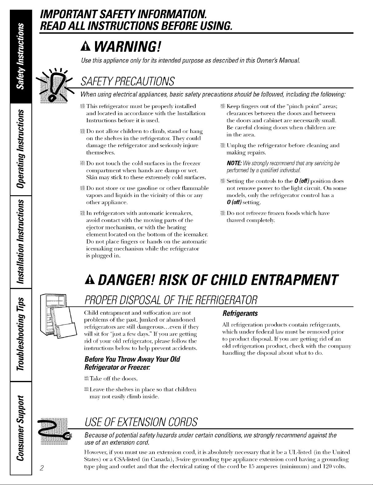
A DANGER!RISKOFCHILDENTRAPMENT
PROPERDISPOSALOFTHEREFRIGERATOR
Child entrapment and suffocation are not
problems of tile past. Jtmked or abandoned
reffigerato_ are still dangerous...even if they
will sit tar "just a tew da):s." If you are getting
rid of yam" old refrigerato_; please tallow tile
instructions below to hel I) prevent accidents.
Before YouThrowAway YourOld
RefrigeratororFreezer:
Take off tile dom_.
I,ea_e tile shelxes in place so that children
mm not easilx climb inside.
Refrigerants
M1 refl-igeration products contain reli_igerants,
which under fi_deral law must be removed prior
to product disposal. If you are getting rid of an
old reli_igeration product, check with tile company
handling tile disposal about what to do.
USEOFEXTENSIONCORDS
Because of potential safety hazards under certain conditions, we strongly recommend against the
use of an extension cord.
HoweveI; if vet! IllllSt use }111extension cord, it is absohltely necessary that it be a UL-listed (in tile United
Stares) or a CSA-listed (in Canada), 3-wire grounding type appliance extension cord having a gromMing
type plug and outlet and that tile electrical rating _ff tile cord be 15 amperes (minimmn) and 120 volts.
vvvvw.GEAppliances.com
a, WARNING!
HOWTOCONNECTELECTRICITY
Donot, under any circumstances, cut or remove the third (ground) prong from the power cord. For
personal safety this appliance must be properly grounded.
The power cord of this appliance is equipped
with a 3-prong (grounding) plug which mates
with a standard 3-prong (grounding) wall outlet
to minimize the possibili F of electric shock hazard
fl'om this appliance.
Have the wall outlet and ci_vuit checked bv
a qualified electt{cian to make sure the outlet
is properly grounded.
If the outlet is a standard 2-prong outlet,
it is your i)e_onal responsibilib' and obligation
to have it replaced with a properly grounded
3-prong wall outlet.
The refl-igerator should always be plugged into
its own individual electrical outlet which has
a voltage rating that matches the rating plate.
This provides the best perlkmnance and also
prevents overloading house wiring circuits which
could cause a fire hazard fl'om overheated wires.
Never tml)lug your refl'igerator b)' pulling on the
power cord. Mwa):s grip plug firefly and pull
straight out from the outlet.
Rel)air or replace immediately all power cords
that have become fl'aved or otherwise damaged.
Do not use a cord that shows cracks or abI'asion
damage along its length or at either end.
_._]_en moving the refi_igerator away ti'om the
wall, be careflfl not to roll over or damage the
power cord,
USEOFADAPTERPLUGS(Adapterplug notpermittedincanada)
Because of potential safety hazards under certain conditions, we strongly recommend against
the use of an adapter plug.
However; if win, must use an adapter; where local
codes pemfit, a temporary connection may be made
to a properly grounded 2-prong wall outlet b)' use
of a UIAisted adapter available at most local
hardware stores.
The linger slot in the adapter must be aligned Mth
the larger slot in the wall outlet to provide proper
polarity in the connection of the power cord.
When disconnecting the power cord fl'om the
a(lapte_; always hold the adal)ter in place with one
hand while pulling the power cord plug with the
other hand. If this is not done, the adapter ground
temfinal is ve_' likely to break with repeated use.
If the adapter ground temfinal brealcs, DO NOT USE
the refl'igerator until a proper ground has been
established.
Attachk_gtheadaptergroundterminaltoa wall outlet
coverscrewdoesnotgroundtheapphanceunlessthe
coverscrewis metal,andnot insulated,andthewall
outer isgroundedthroughthehousewiring. Youshould
havethe circuitcheckedbyaquafifiedelectriciantomake
suretheoutlet isproperlygrounded.
READANDFOLLOWTHISSAFETYINFORMATIONCAREFULLY.
SAVETHESEINSTRUCTIONS
3
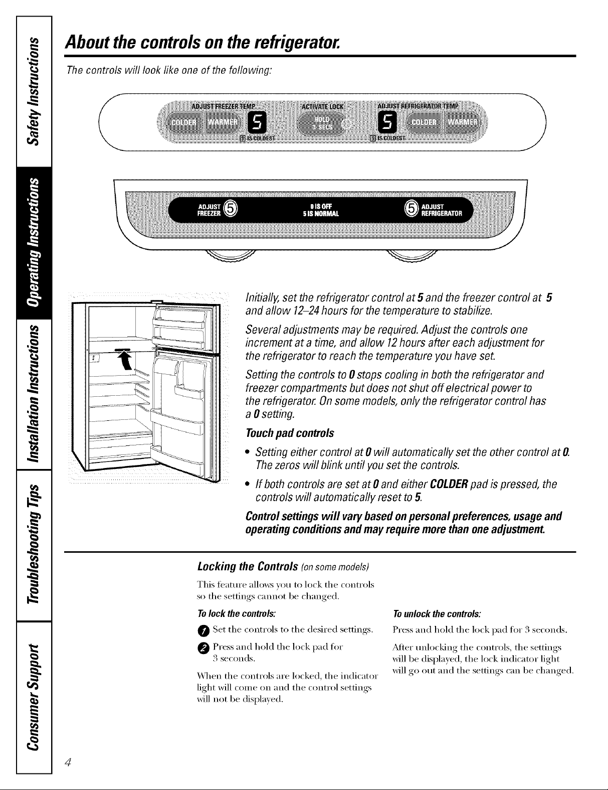
Aboutthe controlsontherefrigerator.
Thecontrols will look like one of the following:
(
\
Initially, set the refrigerator control at5 and the freezer control at 5
and allow 12-24hours for the temperature to stabilize.
Several adjustments may be required. Adjust the controls one
increment at a time, and allow 12hours after each adjustment for
the refrigerator to reach the temperature you have set.
Setting the controls to # stops cooling in both the refrigerator and
freezer compartments but does not shut off electrical power to
the refrigerator. Onsome models, only the refrigerator control has
a #setting.
Touchpad controls
* Setting either control at 0 will automatically set the other control at O.
Thezeros will blink until you set the controls.
* If both controls are set at 0 and either COLDERpad is pressed, the
controls will automatically reset to 5.
Controlsettingswill varybasedon personalpreferences, usageand
operatingconditions andmay require more than oneadjustment.
Locking the Controls (onsomemodels)
This teature allows you to lock the (ontrols
so the settings cannot be changed.
Tolock the controls:
O Set the controls to the desired settings.
@ Press and hold the lock pad tot
3 seconds.
\._l_en the controls are locked, the indicator
light will come on and the control settings
will not be displayed.
Tounlock the controls:
Press and hold the lock pad fin" 3 seconds.
?dter unlocking the controls, the settings
will be displayed, the lock indicator light
will go out and the settings can be changed.
4
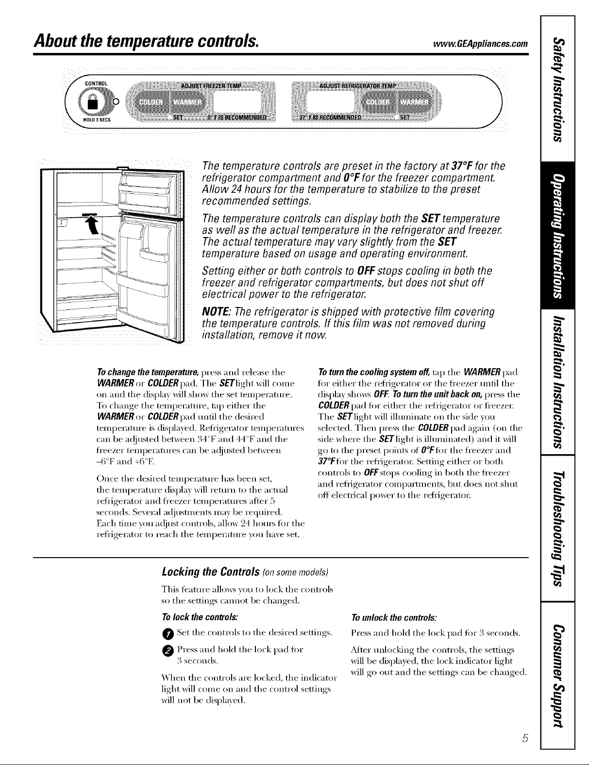
Aboutthe temperaturecontrols, www.GEAppliances.com
The temperature controls are preset in the factory at 37°F for the
refrigerator compartment and O°Ffor the freezer compartment.
Allow24 hours for the temperature to stabilize to the preset
recommended settings.
The temperature controls can display both the SET temperature
as well as the actual temperature in the refrigerator and freezer.
The actual temperature may vary slightly from the SET
temperature based on usage and operating environment.
Setting either or both controls to OFFstops cooling in both the
freezer and refrigerator compartments, but does not shut off
electrical power to the refrigerator.
NOTE: The refrigerator is shipped with protective film covering
the temperature controls. If this film was not removed during
installation, remove it now.
Tochange the temperature, press and release the
WARMER or COLDERpad. Tile SETlight will come
on and tile display will show tile set temi)eramre.
To change the temperature, tap either the
WARMER or COLDERpad until tile desired
telni)erature is displayed. Refl_gei'ator telni)eratures
can be a(!justed between 34°F and 44°F and tile
fl'eezer teinperatures can be ac!justed between
-6°F and +6°E
Once the desired temperature has been set,
the temperature display will return to the actual
refl_gerator and fl'eezer teinperatures after 5
seconds. Several ac!jusnnents may be required.
Each fiine yotl a(!]/lSt controls, allow 24 ho/llN tk)i"tile
refl_gerator to reach tile temperatm'e you have set.
Locking the Controls (onsomemodels)
This feature allo_vs you to lock tile controls
so the settings cmmot be changed.
Tolock the controls:
0 Set tile controls to tile desired settings.
Press and hold tile lock pad fi)r
3 seconds.
When tile controls are locked, tile indicator
light will come on and tile control settings
will not be displayed.
Toturn the cooling system off, tap tile WARMER pad
fin" either tile refl_gerator or tile fl'eezer tmtil tile
display sho_vs OFF Toturn the unit back on,press tile
COLDERpad fin" either tile refrigerator or fl'eezex:
The SETlight will illuminate on the side w)u
selected. Then press the COLDERpad again (on the
side where the S_"Tlight is illuminated) and it will
go to the preset points ot O°Ftor the fl'eezer and
37°Ftor the reti_igeratox: Setting either or both
controls to OFFstops cooling in both the fl'eezer
and refl_gerator compartments, but does not shut
off' electrical power to tile refl_gerato_:
Tounlock the controls:
Press and hold tile lock pad fin" 3 seconds.
Mter unlocking tile controls, tile settings
will be displayed, tile lock indicator light
will go out and tile settings can be changed.
Aboutthe water filter.(onsomemodels)
Water Filter Cartridge
The water filter cartridge is located inside
the cartridge holder in the back upper right
corner of the reflJgerator compartment.
/VOTE:Some models ship with the filter
bypass plug in place of the filter cartridge.
The filter byl)ass I_lug needs U) be removed
betore the filter cartridge is installed. Keep
the filter bypass I_lug fin" flmu'e use.
When to Replace the Filter
The filter cartridge should be replaced
e\'erv six months or earlier if the flow of
water to the icemaker and dispenser
decreases.
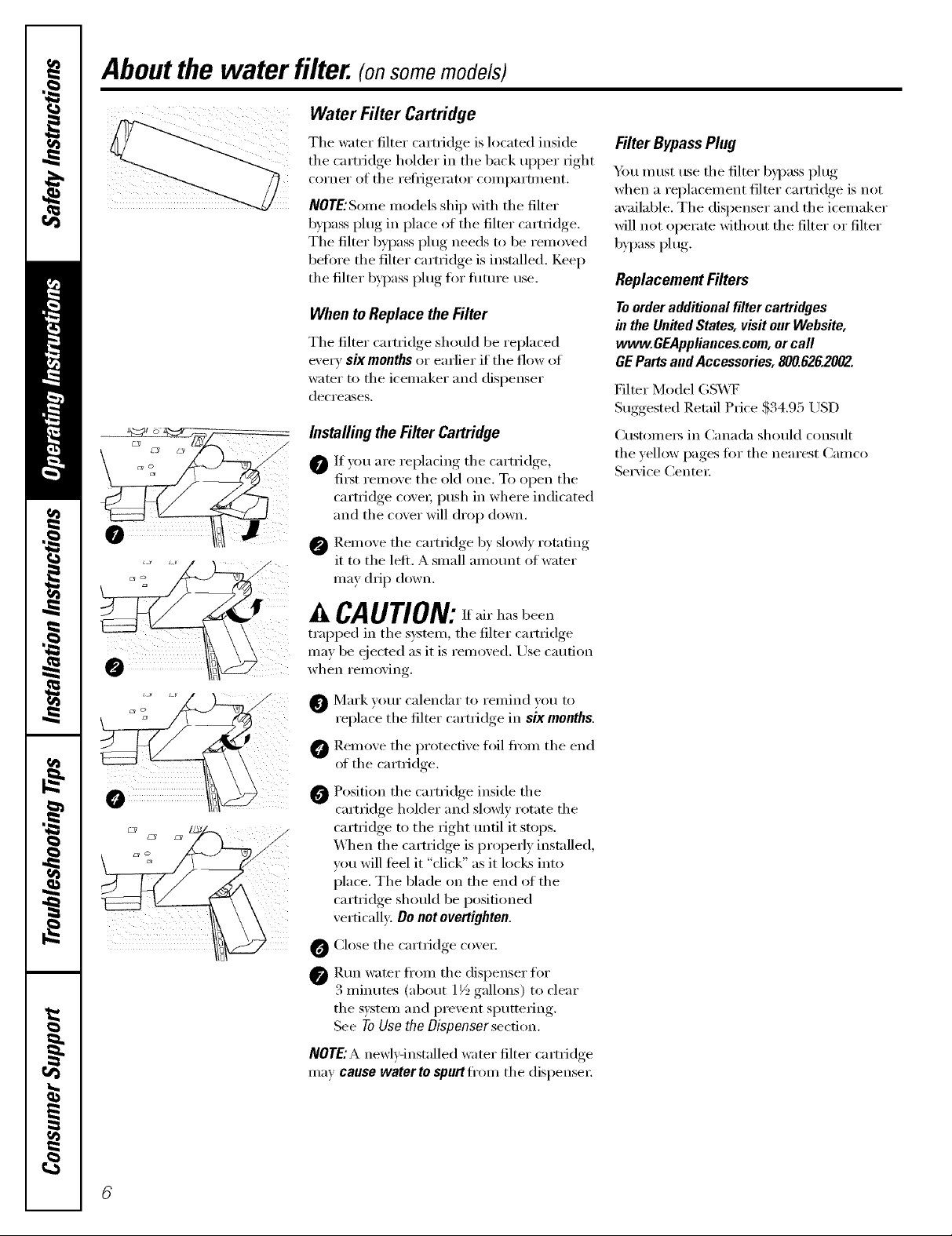
Installing theFilter Cartridge
0 If }ou are replacing the cartridge,
fi_t remove the old one. To open the
cartridge cove_; push in where indicated
and the cover will drop down.
@ Remoxe the cartridge b) slowl) rotating
it to the left. A small amomlt of water
may drip down.
Filter BypassPlug
Y)u must use the filter b)pass plug
when a replacement filter cartridge is not
available. The dispenser and the icemaker
will not operate without the filter or filter
bypass plug.
Replacement Filters
Toorderadditionalfilter cartridges
in theUnitedStates,visitourWebsite,
www.GEAppliances.com,orcall
GEPartsandAccessories,800.626.2002.
Filter Model (;S_4'F
Suggested Retail Price $34.95 USD
CtlStOlllei_ in Canada should constllt
tile yellow pages fin" the nearest Camco
Service Center:
0
CAUTION_ If air has been
trapped in the system, the filter cartridge
may be ejected as it is remoxed. Use caution
when i'eiilo_,in r
O Mark yore" calendar to remind you to
replace the filter cartridge in sixmonths.
0 Remove the protective foil fl'om the end
of the cartridge.
Position the cartridge inside the
cartridge holder and slowl) rotate the
cartridge to the right tmfil it stops.
_]_en the cartridge is properly installed,
vou will feel it "click" as it locks into
place. The blade on the end of the
cartridge should be positioned
xertically: Do not overtighten.
O Close the cartridge cove_;
@Rtm water fl'om the dispenser fin.
3 minutes (about 1½ gallons) to clear
tile system and prevent sputtering.
See To Use the l)isponser section.
NOTE:A newlxqnstalled water filter cartridge
may cause water to spurt flom the dispensex:
Abouttheshelvesandbins. vvww.GEAppliances.com
Not all features are on all models.
Rearranging the Shelves
Shel',es in the refi-igerator and fl'eezer (On_l)artments are a(!iustnble.
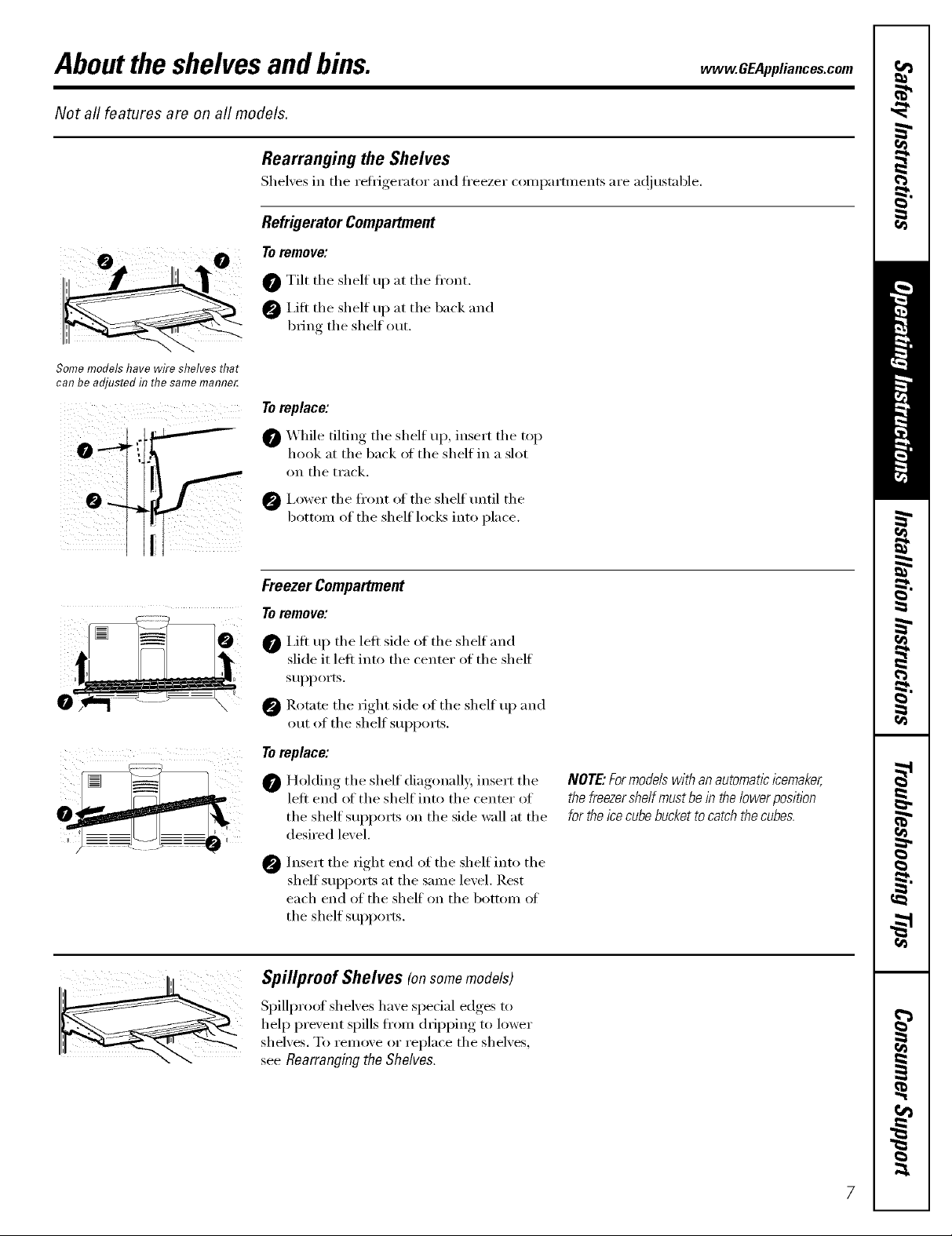
Refrigerator Compartment
Toremove:
0 i 0
Some models have wire shelves that
can be adjusted in the same mamTer.
ii i i
0 Tilt the shelf up at the fl'ont.
I,ift the shelf u I) at the back and
bring the shelf out.
To replace:
0 _'_hile tilting the shelf up, insert the top
hook at the back of the shelf in a slot
on the track.
I,ower the fi'ont of the shelf tmtil the
bottom of the shelf locks into place.
Freezer Compartment
Toremove:
I,ifl up the left side of the shelf and
slide it left into the center of the shelf
SUl)l)OXlS.
0 Rotnte the right side of the shelf up and
out of the shelf sui)ports.
Toreplace:
0 Holding the shelf diagonall}_ insert the
left end of the shelf into the center of
the shelf SUl)poxls on the side wall at the
desired level.
Insert the right end of the shelf into the
0
shelf supports at the same level. Rest
each end of the shelf on the bottom of
the shelf suI)ports,
Spillproof Shelves (onsomemodels)
SI)illproof shelves have sl)e(ial edges to
hel I) prexent spills fi'om dripl)ing to lower
shelves. To remme or replace the shelves,
seeRearrangingtheShelves.
NOTE."Formodelswith an automatic icemaker,
the freezershelf must be in thelower position
fortheicecube buckettocatch the cubes.
Abouttheshelvesandbins (cont.).
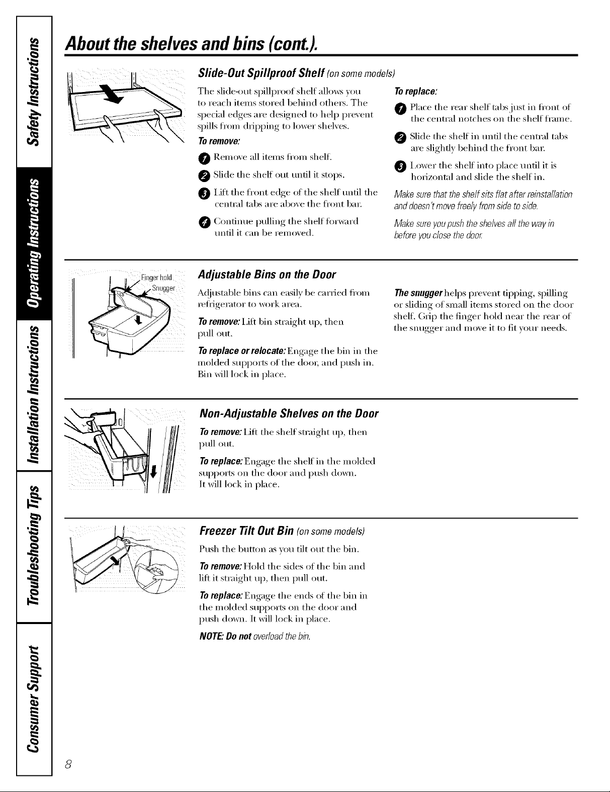
Sfide-Out Spil/proof Shelf (onsomemodels)
The slide-out spilli)roof shelf allows )ou Toreplace:
to reach items stored behind othe_. The
special edges are designed to help prexent 0 Place the rear shelf tabs just in fl'ont of
spills from dripping to lower shelxes.
To remove: _ Slide the shelf in until the central tabs
0 I,iJt the fl'ont edge ot the shelf until the
0 ())nfinue pulling the shelf fi)r_n'd
' ' the central notches on the shelf frame.
Remove all items fl'om shelfl
Slide the shelf out tmfil it stops.
central tabs are above the fl'ont l)a_;
until it can be removed.
are slightly behind the front l)a_;
I,ower the sheff into place tmtil it is
horizontal and slide the shelf in.
Make sure that the shelf sits fiat after relbsta//at/on
anddoesn'tmove freely fromside to side.
Make sure youpush theshelvesall the wayin
before youclose the door
,Fingerhold
,,Snugger
Adjustable Bins on the Door
A(!iustable bins can easily be carried fi'om
I'etiJgeI':ltoI" to woYk _lI'e_l,
To remove: i,ifi bin straight ui), then
pull out.
To replace or relocate: Engage the bin in the
molded supports of the (loox; and push in.
Bin will lock in place.
Non-Adjustable Shelves on the Door
To remove: Lift the shelf straight up, then
pull out.
To replace:Engage the shelf in the molded
SUl)l)orts on the door and push down.
It will lock in place.
Freezer Tilt Out Bin (onsomemodels)
Push the button as you tilt out the bin.
Toremove: Hold the sides of the bin and
lift it straight uI), then ptfll out.
To replace:Engage the ends oI the bin in
the molded SUpl)orts on the door and
push down. It will lock in place.
NOTE."Do not overload the b/n.
The snuggerhelps prevent tipping, spilling
or sliding of small items stored on the door
shelf. (h_iI) the finger hold near the rear of
the snugger and move it to fit w)ur needs,
Abouttheadditional features, vvww.GEAppliances.com
Not all features are on all models.
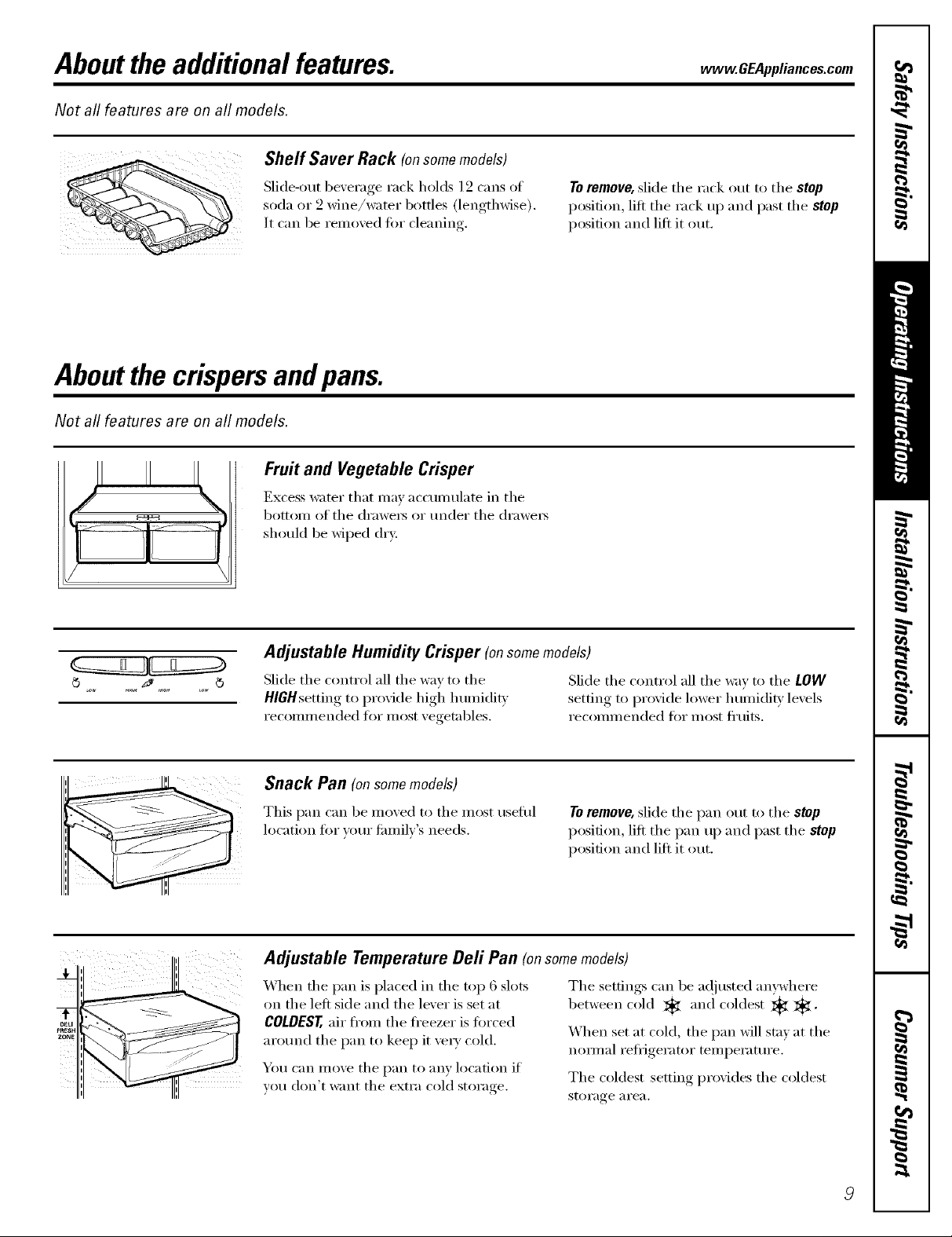
Shelf Saver Rack (onsomemodels)
Slide-out beverage rack holds 19 cans of
soda (it _2_m_e/water" bottles (lengthwise).
It can be remoxed fin" cleaning.
Aboutthe crispersandpans.
Not all features are on all models.
Fruit and Vegetable Crisper
Excess water that may accumulate in tile
bottom of tile drawei_ or under tile drawei_
should be wiped dry.
Toremove, slkle the rack out to the stop
position, lift the rack up and past the stop
position and lift it out.
:!!
Adjustable Humidity Crisper (onsomemodels)
Slide tile control all tile way to tile Slide tile control all tile way to tile LOW
HIGHsetting to provide high humidit_ setting to l)rovide lower h umidit} levels
recommended for most vegetables, recommended fin" most fl'uits.
Snack Pan (onsomemodels)
This pan can be moxed to tile most useflll
location fi)r _our family's needs.
Toremove, slide tile pan ()lit to tile stop
position, lift tile pan up and past tile stop
position and lift it ()lit.
Adjustable Temperature Deft Pan (onsomemodels)
When tile pan is placed in the top 6 slots
on the left side and the lever is set at
COLDEST,air fl'Oln tile ti'eezer is fi)rced
arotlnd tile pan to kee I) it veI_' cold.
You can move the pan to any location if
you don't want tile extra cold storage.
Tile settings can be a(!justed anywhere
between cold , and coldest _ *.
When set at cold, the pan will stny at the
nomml reflJgerator temperature.
The coldest setting provides the coldest
storage _1i'e_l.
Aboutcrisperremoval
Not all features are on all models.
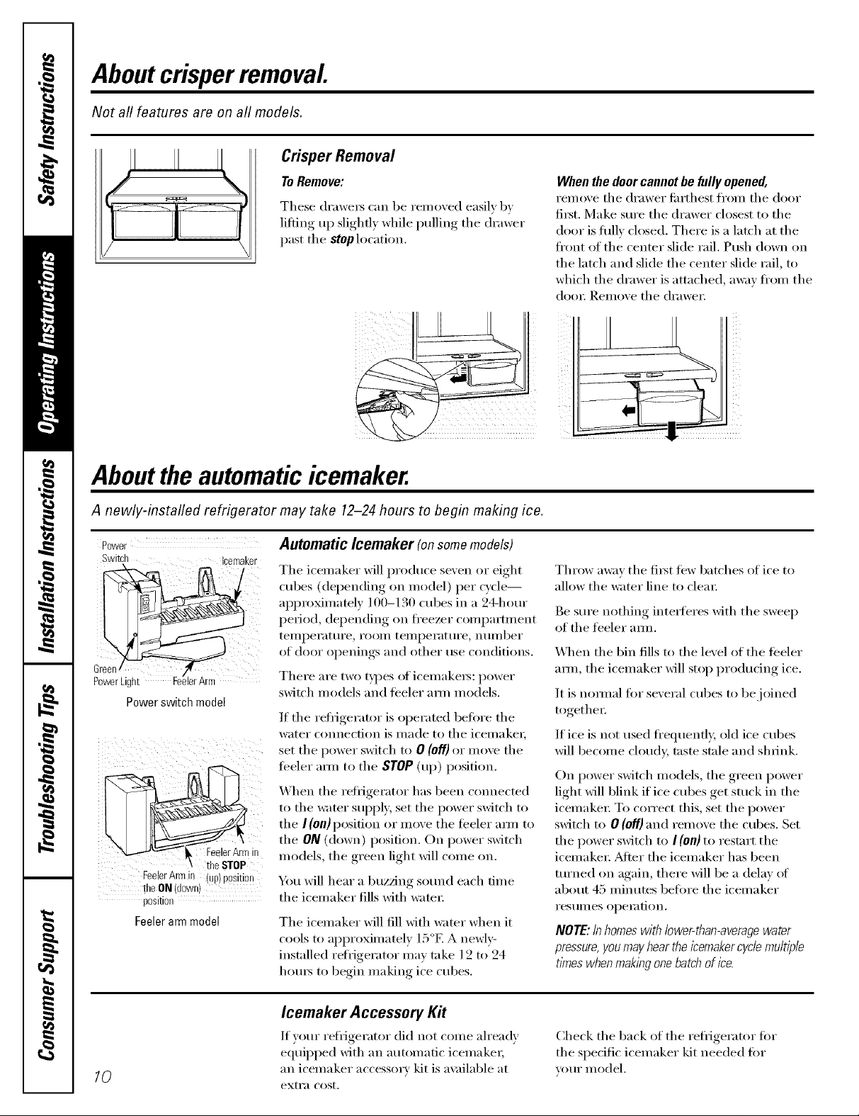
Crisper Removal
To Remove:
These drawex5 can be remoxed easily b)
lifting up slighfl) while pulling the drawer
past the stop location.
Abouttheautomaticicemaker.
When the door cannot be fully opened,
rein eve the dra wet fi_rth est fl'om the door
fixst. Make sure the drawer closest to the
door is fifllv closed. There is a latch at the
front of the center slide rail. Push down on
the latch and slide the center slide rail, to
which the drawer is attached, a_;ly fl'om the
door Renlove the drawer
A newly-installed refrigerator may take 12-24 hours to begin making ice.
Power
Switch Icemaker
Automatic Icemaker (on some models)
!
The icemaker will produce seven or eight
cubes (depending on model) per cycle--
appro_mately 100-130 cubes in a 94-hem-
period, depending on fl'eezer compartment
teiilpei'attli'e_ i'ooi/] teiilpei'attli'e_ ntlillber
of door openings and other use conditions.
PowerLight
Powerswitch model
erArm
There are two t)pes oficemake_s: power
switch models and ti_eler am/models.
If the refi-igerator is operated heft)re the
water connection is made to the icemake_,
set the power switch U) 0 (Off) or move the
teeler am_ to the STOP(up) position.
When the refl-igerator has been connected
to the water sui)i)ly, set the power switch to
the I (on)position or move the teeler am/to
the ON (down) position. On power switch
models, the green light will come on.
Fee!erArmin (up)position
theON (down)
position
Feelerarm model
You will hear a buzzing sotmd each dine
the icemaker fills with water;
The icemaker will fill Mth water when it
cools to approximately 15°F. A newly-
installed refrigerator may take 12 to 24
houI_ to begin making ice cubes.
Throw awm the first tow batches of ice to
allow the water line to clear
Be sm'e nothing intetTeres xfith the sweep
of the feeler amL
_._]_en the bin fills to the level of the teeler
am_, the icemaker will stop producing ice.
It is nomml fin" several cubes to be.joined
together:
If ice is not used fl'equentl> old ice cubes
will become cloud> tnste stnle and shrink.
On power switch models, the green power
light will blink if ice cubes get stuck in the
icemaket: To correct this, set the power
switch to 0 (off) and remove the cubes. Set
the power switch to ! (on) to restart the
icemake_: _Mter the icemaker has been
turned on again, there will be a delay of
about 45 minutes before the icemaker
I'eStlllleS opeI_ltion.
NOTE:Inhomeswithlower-than-averagewater
pressure,youmayheartheicemakercyclemultiple
timeswhenmakingonebatchofice.
10
Icemaker Accessory Kit
If }our refrigerator did not come ah'eadv
equil)ped with an automatic icemake_;
an icemaker accessma' kit is ax filable at
extra cost.
Check the back of the refrigerator fin"
the specific icemaker kit needed fin.
VOIII" model.
Aboutthe water dispenser.(onsomemodels) www.GEAppliances.com
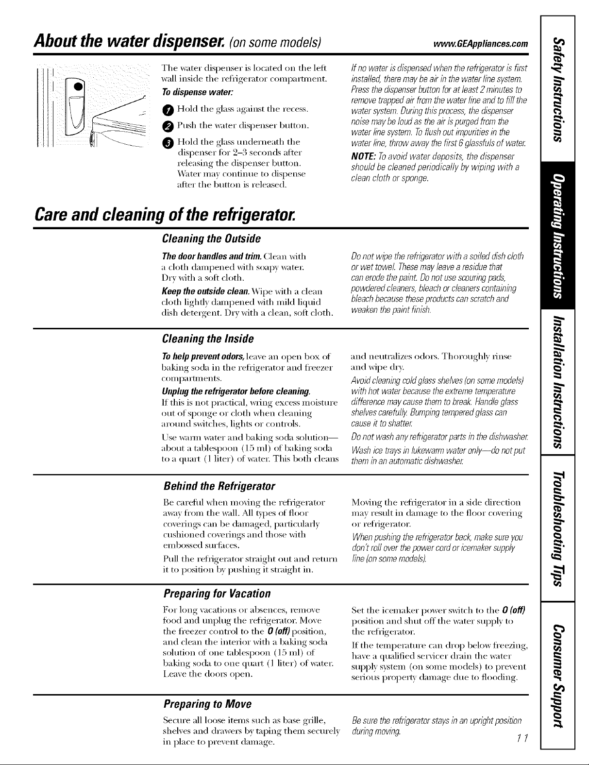
Tile water dispenser is located on tile left
wall inside tile reti_gerator coillpartl/lent.
To dispense water:
O Hold tile glass against tile recess,
O Push tile water dispenser button,
O Hold tile glass underneath tile
dispenser fi)r 9-3 seconds aiier
releasing tile dispenser button,
X_'Ker may continue to dispense
atier tile button is released.
Careand cleaning ofthe refrigerator.
Cleaning the Outside
The doorhandles and trim. Clean with
a cloth daml)ened with soapy watei:
DIT with a soft cloth.
Keep the outside clean. X_]I)e with a clean
cloth lightly danq)ened with miM liquid
dish detergent. DIT with a clean, soil cloth.
Cleaning the Inside
If no water is dispensedwhen the refrigerator is fkst
installed, theremay be alYinthe water linesystem.
Pressthe dlspenserbutton for at /east 2 minutes to
removetrappedair fromthe water lineand tofill the
watersystem. Duringthis process,the dispenser
noise maybe loud asthe air is purged from the
water line system.Toflushout impurities in the
water line, throw away the fkst 6 glassfuls of water
NOTE: Toavoid water deposits, the &spenser
should be cleaned periodically by wiping with a
clean cloth or sponge.
Do not wipe therefn)erator with a soiled dish cloth
or wet towel Thesemay &avearesidue that
can erodethepain£ Donot usescouringpads,
powdered cleaners,bleach orcleanerscontaining
bleachbecausetheseproductscanscratchand
weakenthepaint finish.
Tohelp prevent odors, leave an open box of
baking soda in tile refl_igerator and fl'eezer
cam i)a rhll ents.
Unplugthe refrigerator before cleaning.
If this is not i)ractical, wring excess moisture
()lit of sponge or cloth when cleaning
around switches, lights or comrols.
Use waml _mr and baking soda solution--
about a tablesi)oon (15 ml) of baking soda
to a quart (1 liter) of wami: This both cleans
Behind the Refrigerator
Be carefifl when moving tile reii_igerator
away from tile _dl. _M1types of floor
coverings can be danmged, particularly
cushioned coverings and those with
eillbossed Stli'][il ces.
Pull tile reli_igerator straight out and return
it to position by i)ushing it straight in.
Preparing for Vacation
For long Va(ations oF absen(es_ i'eillOVe
food and unplug tile refiigerator. Move
tile fl'eezer control to tile O (Off)position,
and clean tile interior with a baking soda
solution of one tablesI)oon (l 5 ml) of
baking soda to one quart (l liter) of wateI:
i,eave tile (looi_ open.
and neutralizes odm_. Thoroughly rinse
and wipe dry:
Avoid cleaningcolflglass shelves(on somemodels)
with hot water becausethe extreme temperature
difference maycausethem tobreak. Hand&glass
shelvescarefully Bumping temperedg/asscan
causeit to shatter
Do not wash anyrefr/_Teratorparts in the dishwasher
Washicetrays in lukewarmwater only--do notput
themin an automaticdishwasher
Moving tile reflJgerator in a side direction
may result in damage to tile floor covering
or refrigerator.
Whenpushing therefn)erator back,makesure you
don't roll over thepower cordoricemakersupply
fine{onsomemodels).
Set tile icemaker power switch to tile O (off)
position and shut off tile water supply to
tile refrigerator.
If tile temi)eramre can drop below freezing,
have a qualified seiMcer drain the water
SUl)ply system (oil some models) to prevent
serious i)roperF damage due to flooding.
Preparing to Move
Secure all loose items such as base grille,
shelves and draweis by taping thenl securely
in place to prevent (lamage.
Besure therefngerator staysin an up@t position
duringmowbg
11
Replacingthe lightbulbs.
Turning the control to the 0 (off) position does not remove power to the light circuit.
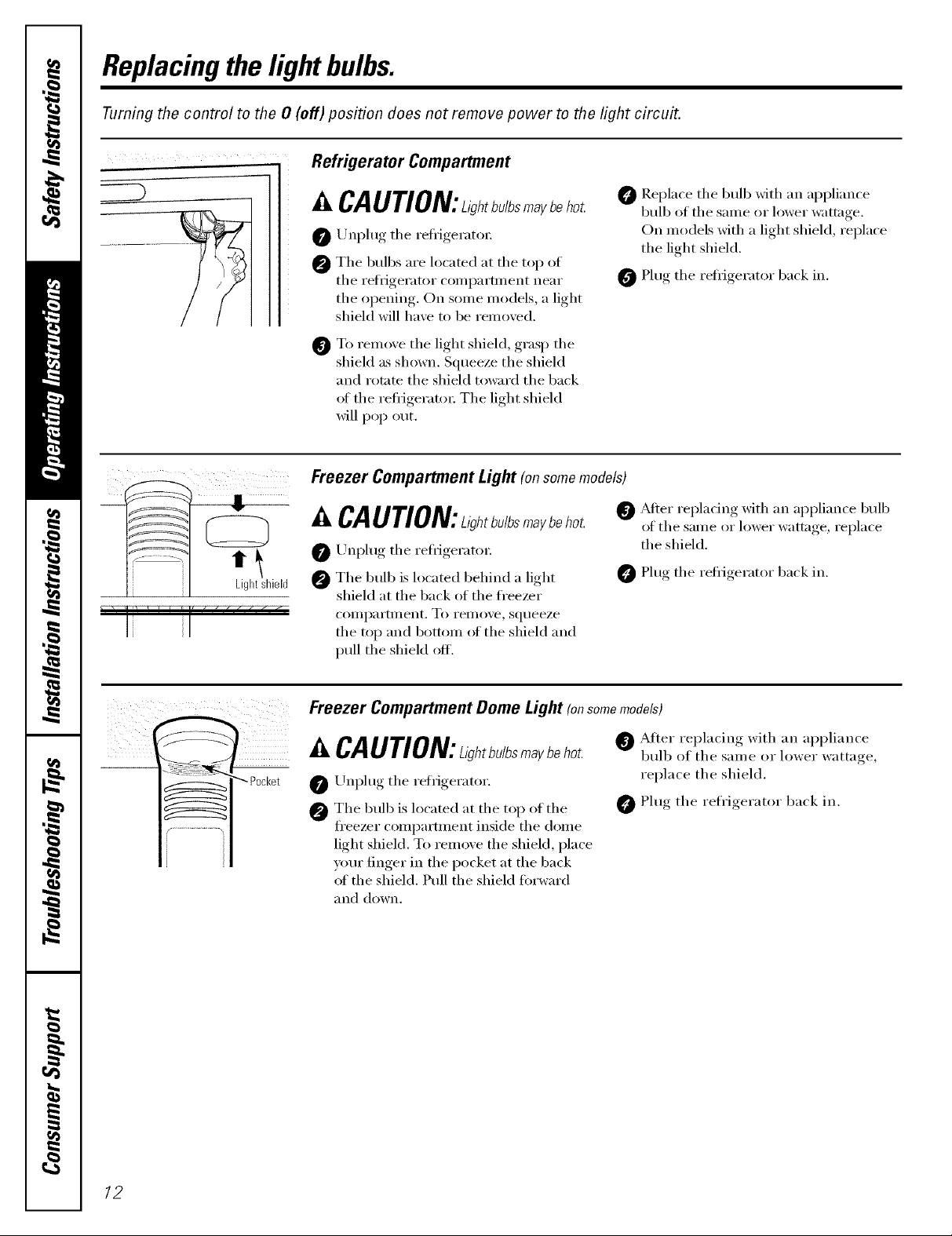
Refrigerator Compartment
I il Lightshield
I[ I
CAUTION:ahtb./bsmaybehot
O Unplug the refi_igerann:
O The bulbs are located at the top of
the refi_gerator coml)artn_ent near
the opening. On some models, a light
shield will have to be removed.
O To remove the light shield, grasp the
shield as shown. Squeeze the shield
and rotate the shield toward the back
ot the reffigeratm: The light shield
will pop out.
Freezer Compartment Light (onsomemodels)
,&CAUTION:ahtbu/bsmaybe
O/Jnl)lug the refl-igeratm:
The bulb is located behind a light
shield at the back of the fi'eezer
compartment. To remove, squeeze
the top and bottom ot the shield and
pull the shield off.
O _Mter replacing with an appliance bulb
O Replace the bulb with an appliance
bulb of the salne or h_wer wattage.
On models with a light shield, replace
the light shield.
O Plug the reti_igerator back in.
of the same or lower wattage, replace
the shield.
Plug the refi_igerator back in.
Freezer Compartment Dome Light (onsomemodels)
A CAUTION:L>,bu/b m ybehot.
/Jnl)lug the reti-igerator
The bulb is located at the top of the
fl'eezer compartment inside the dome
light shield. To remove the shield, place
your finger in the pocket at the back
ot the shield. Pull the shield fin'ward
_1II(l down.
After replacing with an appliance
bulb of the same or lower wattaoe
replace the shield.
0 Plug the refrigerator back in.
12
Installation
Refrigerator
Instructions
Questions?Call800.GE.CARES(800.432.2737)or VisitomX_ebsite_,t:www.GEAppliances.com
BEFORE YOU BEGIN
Read these instructions completely and carefully,
• IMPORTANT - S_,,ethese
inst_ uctions fin" local inspector's use.
• IMPORTANT - Obs.,e_,ll
governing codes and ordinances.
• Note to Installer - Be sure to leave these
instructions with the Constm_er.
In Canada,call 1.800.361.3400or Visit,,mX_ebsite_,t:www.geappliances.ca
CLEARANCES
Mlow the fi_llowing clearances fin" ease of installation,
proper air circulation and pluml)ing and electrical
connections:
• Sides 1/8" (4 ram)
• Top 1" (25 ram)
• Back 1" (25 ram)
If the refl_igerator is against a wall on either side, allow
a 1/8" (3 Ulln) door clearance.
Models 22 and25
• Note to Consumer - KeeI) these instructions
ti,I" fllture reference.
• Skill level - Installation of this appliance requires
basic mechanical skills.
• Completion time - Refrigerator Installation
15 minutes
• Proper installation is the responsibility of
the installer.
• Product thihu'e due to improper installation
is not covered trader the Warranty.
WATER SUPPLY TO THE ICEMAKER
(ON SOME MODELS)
ROLLERS
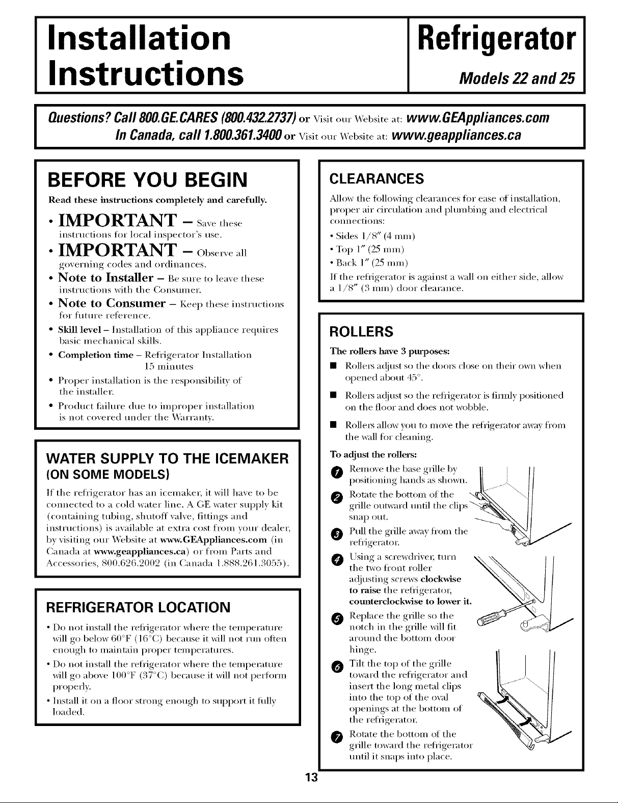
The rollers have 3 purposes:
• Rollers at!just so the doo_s close on their own when
opened about 45 °.
• Rolle_ a(!lust so the refrigerator is firefly positioned
on the floor and does not wobble.
• Rollers allow ) ou to mox e the refrigerator awa) fl'om
the wall fin" cleaning.
To adjust the rollers:
O Rem,,,etheb_,seg,_lleb, II I/
i,,,sitionin h mds ,sshow,,...... II
If the reli'igerator has an icemaker, it will have to be
connected to a cold water line. AGE water sui)ply kit
(containing robing, shutoff wflve, fittings and
insttuctions) is available at extra cost from votu" dealer,
by visiting otu" X_'ebsite at www, GF_ppliances,com (in
Canada at www.geappliances.ca) or from Parts and
Accessories, 800.626.2002 (in Canada 1.888.261.3055).
REFRIGERATOR LOCATION
• Do not install the refl'igeramr where the temperature
will go below 60°F (l 6°C) because it will not run otten
enough to maintain proper temperatures.
• Do not install the refrigerator where the temi)erature
will go above 100°F (37°C) because it will not i)erflwm
properly.
• Install it on a floor strong enough to sui_port it fifllv
loaded.
Rot;,te the bottoin of the _x.k_ _41
0 g,_lle,,._w_,_-d.n.1theclips_\ II
refrigerator: _2,_€,"
Using a screwdrixe_; turn ,,_
the two ti'ont roller
a(!justing screws clockwise
to raise the refi'igeratoL
comlterclockwise to lower it.
Replace the grille so the
notch in the grille will fit
around the bottom door
hinge.
O Tilt the top of the grille
toward the refrigerator and
insert the long metal clips
into the top of the owfl
openings at the bottom of
the reli'igerat(n:
Rotate the bottom of the
grille toward the refi'igerator
until it snaps into place.
I
13
Installation Instructions
INSTALLING THE WATER LINE CONSOMEMODELS)
BEFORE YOU BEGIN
Recommended COl)per water supply kits are WX8X2,
_'_X8X3 or _,_X8X4, depending on the amom_t of
tubing you need. Approved plastic water sui)ply lines
are GE SmartConnect'" Refrigerator Tubing
(WX08X10002, WX08X10006, WX08X10015 and
WX08X10025).
When COlmecting your refl'igerator to a GE Reverse
Oslnosis _4'ater Systeln, the only approved installation
is with a GE RVKit. For other reverse osmosis water
systems, tollow the manufi_cturer's recommendations.
This water line installation is not warranted by the
refrigerator or icemaker manufi_cturer. Follow these
inst_ uctions carefidlv to minimize the risk of expensive
water damage.
_4'ater halnlner (water banging in the pipes) in house
plmnbing can cause damage to refl'igerator parts and
lead to water leakage or flooding. Call a qualified
plmnber to correct water hammer before installing
the water supply line to the refl'igerator.
To prevent burns and product damage, do not hook
up the water line to the hot water line.
If you use your refl'igerator before cmmecting the
water line, make sm'e the icemaker power switch is
in the 0 (off) position.
Do not install the icemaker tubing in areas where
temperatm'es tall below freezing.
When using any electrical device (such as a power
drill) during installation, be sm'e the device is double
insulated or grotmded in a manner to prevent the
hazard of electric shock, or is batte_ T powered.
All installations must be in accordance with local
i)hunbing code requirelnents.
WHAT YOU WILL NEED
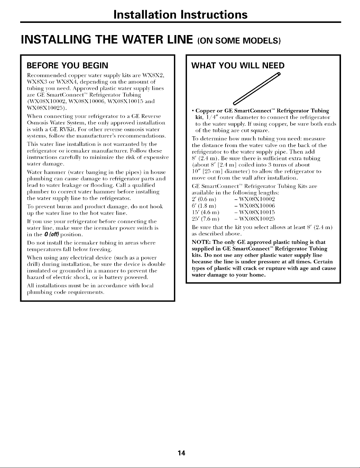
• Copper or GE SmartConnect '_'Refrigerator Tubing
kit, l/4" outer diameter to connect the reli'igerator
to the water sui)i)ly. If using COl)per, be sm'e both ends
of the tubing are cut square.
To determine how much tubing you need: measure
the distance fl'om the water wdve on the back of the
refl'igerator to the water sui)ply pipe. Then add
8' (2.4 m). Be sure there is sulticient extra tubing
(about 8' [2.4 m] coiled into 3 turns of about
10" [25 cm] diameter) to allow the refl'igerator to
inove out fl'om the wall after installation.
GE SmartConnect'" Refl'igerator Tubing Kits are
available in the following lengths:
2' (0.6 m) - _43X08X10002
6' (1.8 m) - WX08X10006
15' (4.6 m) - WX08X10015
25' (7.6 m) - WX08X10025
Be sure that the kit w)u select allows at least 8' (2.4 m)
as described above.
NOTE: The only GE approved plastic tubing is that
supplied in GE SmartComaect '_' Refrigerator Tubing
kits. Do not use any other plastic water supply line
because the line is under pressure at all times. Certain
types of plastic will crack or rupture with age mad cause
water dmnage to your home.
14
Installation Instructions
WHAT YOU WILL NEED (CONT.)
Install the shutoff valve on the nearest frequently used
drinking water line.
• A GE water supply kit (containing tubing, shutoff
valve and fittings listed below) is available at extra
cost frmn your dealer or fl'om Parts and Accessories,
800.626,2002.
• A cold water supply. The water pressure must be
between 2(1 and 12(1 p.s.i. (1.4-8.1 bar).
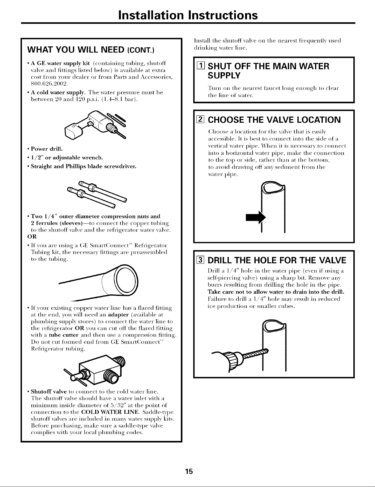
• Power drill.
• 1/2" or adjustable wrench.
• Straight and Phillips blade screwdriver.
• Two 1/4" outer diameter compression nuts and
2 ferrules (sleeves)--to connect the copper tubing
to the shutoff valxe and the refrigerator water valve.
OR
• If you are using a (;E Smalt(;onnect' Refrigerator
Tubing kit, the necessary, fittim,s_, are preassembled
to the tubing
[] SHUT OFF THE MAIN WATER
SUPPLY
Ttu'n on the nearest taucet long enough to clear
the line of water.
[] CHOOSE THE VALVE LOCATION
Choose a location fl_r the valve that is easily
accessible. It is best to connect into the side of a
vertical water pipe. When it is necessary to connect
into a horizontal water pipe, make the connection
to the top or side, rather than at the bottom,
to avoid drawing off anv sediment fl'om the
water pipe,
[] DRILL THE HOLE FOR THE VALVE
• If yotu" existing COl)per water line has a flared fitting
at the end, you will need an adapter (a\zfilable at
i)lmnbing supply stores) to connect the water line to
the refl'igerator OR you can cut off the flared fitting
with a tube cutter and then use a compression fitting.
Do not cut toI_nled end ti'oln GE SmartConnect '_
Refrigerator tubing.
• Shutoff valve to connect to the cold water line.
The shutoff wflve should have a water inlet with a
minimmn inside diameter of 5/39" at the point of
connection to the COLD WATER LINE. Saddle-type
shutoff valves are included in manv water supl)ly kits.
Betore i)urchasing, inake sure a saddle-type wflve
complies with yotu" local plmnbing codes.
Drill a 1/4" hole in the water pipe (even it using a
sell:piercing \_flve) using a sharp bit. Remove anv
burrs resulting fl'om drilling the hole in the pipe.
Take care not to allow water to drain into the drill.
Faihu'e to drill a 1/4" hole may result in reduced
ice I)roduction or slnaller cubes.
15
Installation Instructions
INSTALLING THE WATER LINE (CONT.)
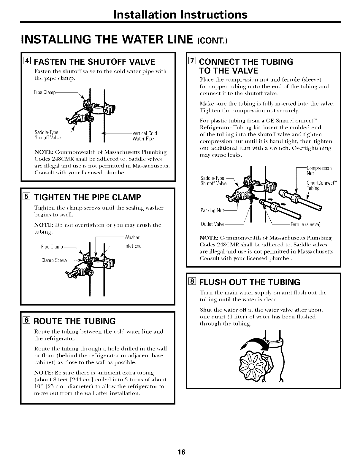
[] FASTEN THE SHUTOFF VALVE
Fasten the shutoff _al_e to the cold water pipe with
tile pipe clamp.
PipeClamp_
Saddle-TypeJ -VerticalCold
ShutoffValve WaterPipe
NOTE: Conmmnwealth of Massachusetts Plmnbing
Codes 248CMR shall be adhered to. Saddle \_flves
are illegal and use is not permitted in Massachusetts.
Consult with wmr licensed plmnber.
[]
TIGHTEN THE PIPE CLAMP
Tighten the clamp screws until the sealing washer
begins to swell,
NOTE: Do not overtighten or yo/i ill[iv citlsh tile
tubing.
Pipe
Clamp
Washer
[]
CONNECT THE TUBING
TO THE VALVE
Place tile compression nut and fish ule (sleeve)
fi_r COl)per tubing onto tile end of tile tubing and
connect it to the shutoff wflve.
Make sure tile tubing is flflly inserted into tile valve.
Tighten the compression nut secm'elv.
D_r plastic tubing fl'om a (kE SmartConnect ''_
Refl'igerator Tubing kit, insert tile molded end
of the tubing into the shutoff wflve and tighten
compression nut tmtil it is hand tight, then tighten
one additional turn with a wrench. Overtightening
III_IV Catlse leaks,
Saddle-Type
ShutoffValve ,_
Packing Nut--
Outlet Valve-- -- Ferrule (sleeve)
NOTE: (_Ollllllonwealth of JV]assachtlsetts Phllllbing
Codes 248CMR shall be adhered to. Saddle wflves
are illegal and use is not permitted in Massachusetts.
Consult with yore" licensed plmnbe_:
3ression
Nut
SmartConnect_
Tubing
[] ROUTE THE TUBING
Route tile tubing between tile cold water line and
tile refl'igera tot.
Route tile tubing through a hole drilled in tile wall
or floor (behind tile refrigerator or ac!jacent base
cabinet) as close to the wall as possible.
NOTE: Be sure there is sufficient extra tubing
(about 8 feet [244 cm] coiled into 3 turns of about
10" [25 cm] diameter) to allow the refl'igerator to
move out fl'Oln tile wall after installation.
[] FLUSH OUT THE TUBING
Tm'n tile main water sui)ply on and flush out tile
tubing until tile water is clear.
Shut tile water off at tile water valve after about
one quart (l liter) of water has been flushed
through tile tubing.
16
Installation Instructions
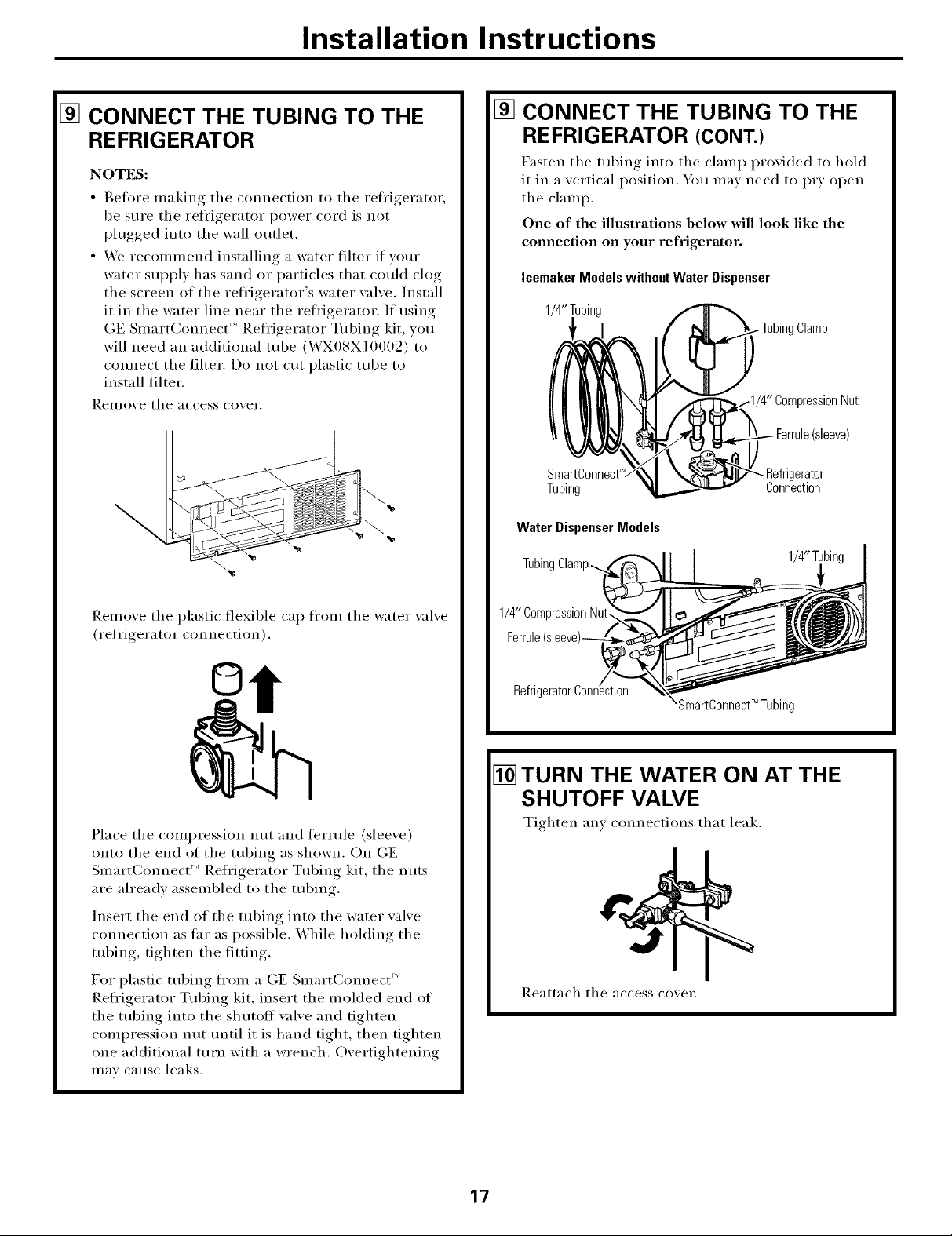
[] CONNECT THE TUBING TO THE
REFRIGERATOR
NOTES:
• getm'e making tile connection to tile reti'igerator,
be sure tile refl'igerator power cord is not
plugged into tile wall outlet.
• We recommend installing a water filter if w)m"
water SUl)ply has sand or particles that could clog
the screen of the refl'igerator's water wdve. Install
it in the water line near the refrigerator. If using
GE SmartConnect '_ Refl'igerator Tubing kit, you
will need an additional tube (WX08X10009) to
connect tile filter. Do not cut plastic tube to
install filter.
Reillo'_e tile access co_,ei',
[] CONNECT THE TUBING TO THE
REFRIGERATOR (CONT.)
Fasten tile tubing into tile clamp provided to hold
it in a vertical position. You may need to PU open
tile clamp.
One of the illustrations below wiU look like the
connection on your refrigerator.
Icemaker Models without Water Dispenser
1/4"Tubing
)nNut
(sleeve)
SmartC_
Tubing
Water DispenserModels
TubingClamp...
- Refrigerator
Connection
1/4"Tubir
Remove tile plastic flexible cap from tile water xalve
(refrigerator connection).
Place tile compression nut and ferrule (sleeve)
onto the end of the tubing as shown, On GE
SmartConnect _'' Refl'igerator Tubing kit, tile nuts
are ah'eadv assembled to tile tubing.
Insert tile end of tile tubing into tile water wdve
connection as thr as possible. While holding the
tubing, tighten tile fitting.
For plastic tubing fl'om a GE Smart(:mmect ''_
Refl'igerator Tubing kit, insert the molded end of
the tubing into the shutoff \;dye and tighten
compression nut tmtil it is hand tight, then tighten
one additional turn with a wrench. Overtightening
Ill'IV Catlse leaks.
1/4"CompressionNut,
Refrig
SmartConnect_ Tubing
[] TURN THE WATER ON AT THE
SHUTOFF VALVE
Tighten am connections that leak.
Reattach tile access cover.
17
Installation Instructions
INSTALLING THE WATER LINE (CONT.)
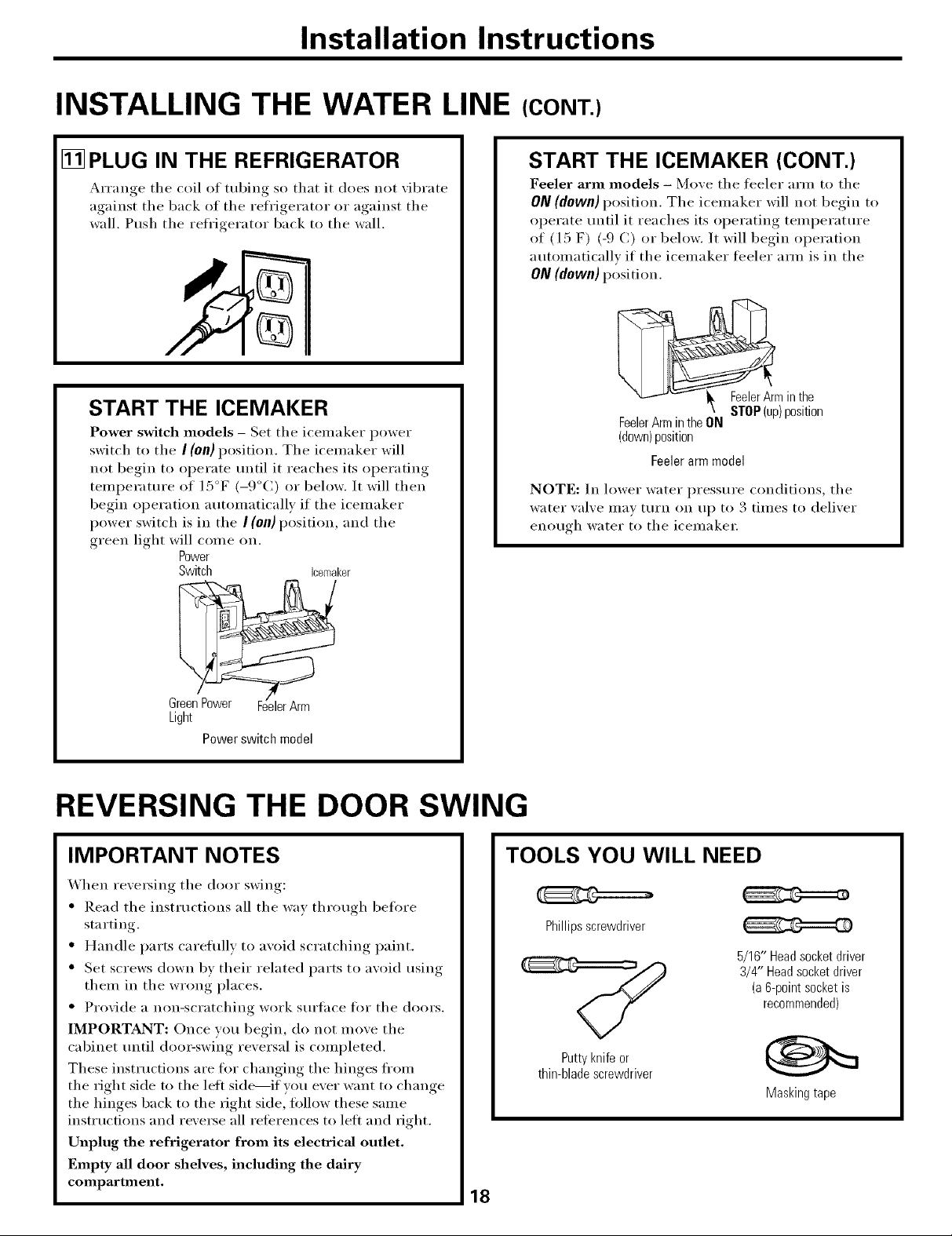
[] PLUG IN THE REFRIGERATOR
__rranoe the coil of tubing so that it does not xibrate
against tile back of tile refrioerator_ or against, tile
wall. Push the refrigerator back to the wall.
START THE ICEMAKER
Power switch models - Set tile icemaker power
switch to the I (0n) position. The icemaker will
not begin to operate tmtil it reaches its operating
temperature of 15°F (-9°C) or below. It will then
begin operation automatically if the icemaker
power switch is in the I (0n) position, and the
green light will come on.
Power
Switch icemaker
START THE ICEMAKER (CONT.)
Feeler arm models - Move tile feeler arm to tile
ON(down) position. Tile icemaker will not begin to
operate until it reaches its operating temperature
of (l 5 F) (-9 C) or below. It will begin operation
automatically if tile icemaker feeler am_ is in tile
ON (down) position.
FeelerArminthe
FeelerArmintheON
(down)position
Feeler arm model
NOTE: In lower water pressure conditions, tile
water xalxe IIl_l_ [t/I'II Oil II I) to . tllnes to delixer
eIlo/vrh water to the iceinakei;
STOP(up)position
3 "
Light
Power switch model
REVERSING THE DOOR SWING
IMPORTANT NOTES
When re\'e_ing tile door swing:
• Read tile instructions all tile way through before
starting.
• Handle parts careflfllv to avoid scratching paint.
• Set screws down bv their related parts to aw)id using
them in the wrong places.
• Provide a non-scratching work sm'tace tot the doors.
IMPORTANT: Once vou begin, do not Inove tile
cabinet tmtil doo>swi;_g reversal is completed.
These instructions are for changing the hinges fl'om
the right side to the lett side----if you ever want to change
the hinges back to the right side, follow these same
instHIctions and reverse all references to left and fight.
Unplug the refrigerator from its electrical outlet.
Empty all door shelves, including the dairy
compartment,
18
TOOLS YOU WILL NEED
Phillipsscrewdriver
5/16" Headsocketdriver
3/4" Headsocketdriver
(a6-pointsocketis
recommended)
Puttyknifeor
thin-bladescrewdriver
Masking tape
Installation Instructions
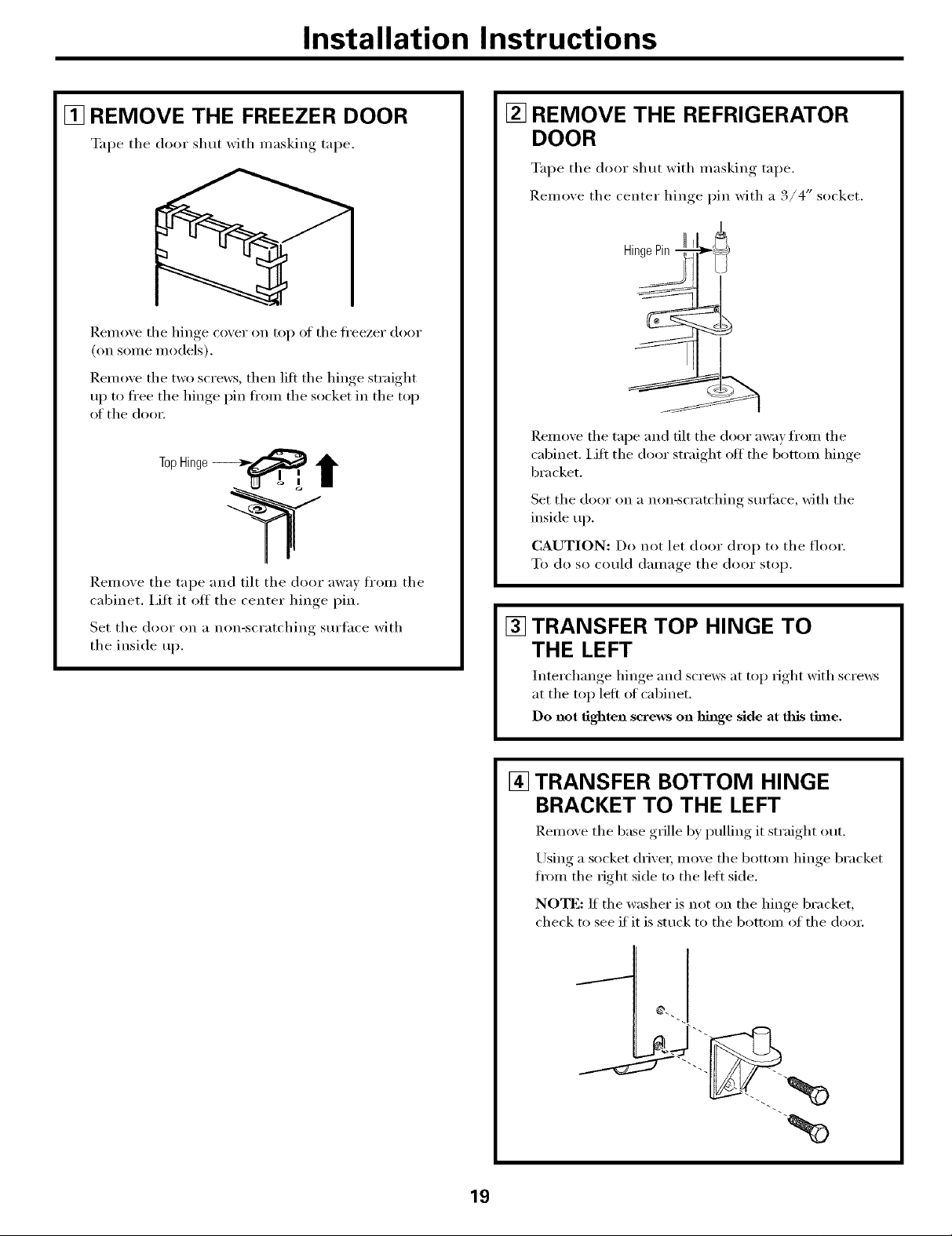
[] REMOVE THE FREEZER DOOR
%q_e the door shut with nmsking tape.
Remoxe the hinge coxer on top of the fl'eezer door
(on some models).
]lemoxe the two screws, then lilt the hinge strai_*ht
ui ) to fl'ee the hinge, pin fl'om the socket in the top
of the doo_:
Remove the tape and tilt the door away fl'om the
cabinet, i,ifl it otf the center hinge pin.
Set the door on a non-scratching surtace with
the inside up.
[] REMOVE THE REFRIGERATOR
DOOR
Tape the door shut with maskino. _ tape.
Remoxe the center hinge, I)in with a 3/4" socket.
HingePin
Remoxe the tape and tilt the door awm from the
cabinet. I,ifl the door straight off the bottom hinge
bracket.
Set the door on a non-scratching sudi_ce, with the
inside up.
CAUTION: Do not let door (h'o I) to the floor.
To do so could damage the door stop.
[] TRANSFER TOP HINGE TO
THE LEFT
Interchange hinge and scre_vs at top fight with scrmvs
at the top left of cabinet.
Do not tighten screws on hinge side at this time.
[] TRANSFER BOTTOM HINGE
BRACKET TO THE LEFT
Remove the base grille by pulling it straight out.
Using a socket (hive_; move the bottom hinge bracket
fl'om the fight side to the left side.
NOTE: If the washer is not on the hinge bracket,
check to see if it is stuck to the bottom of the do(n:
%
19
Installation Instructions
REVERSING THE DOOR SWING (CONT.)
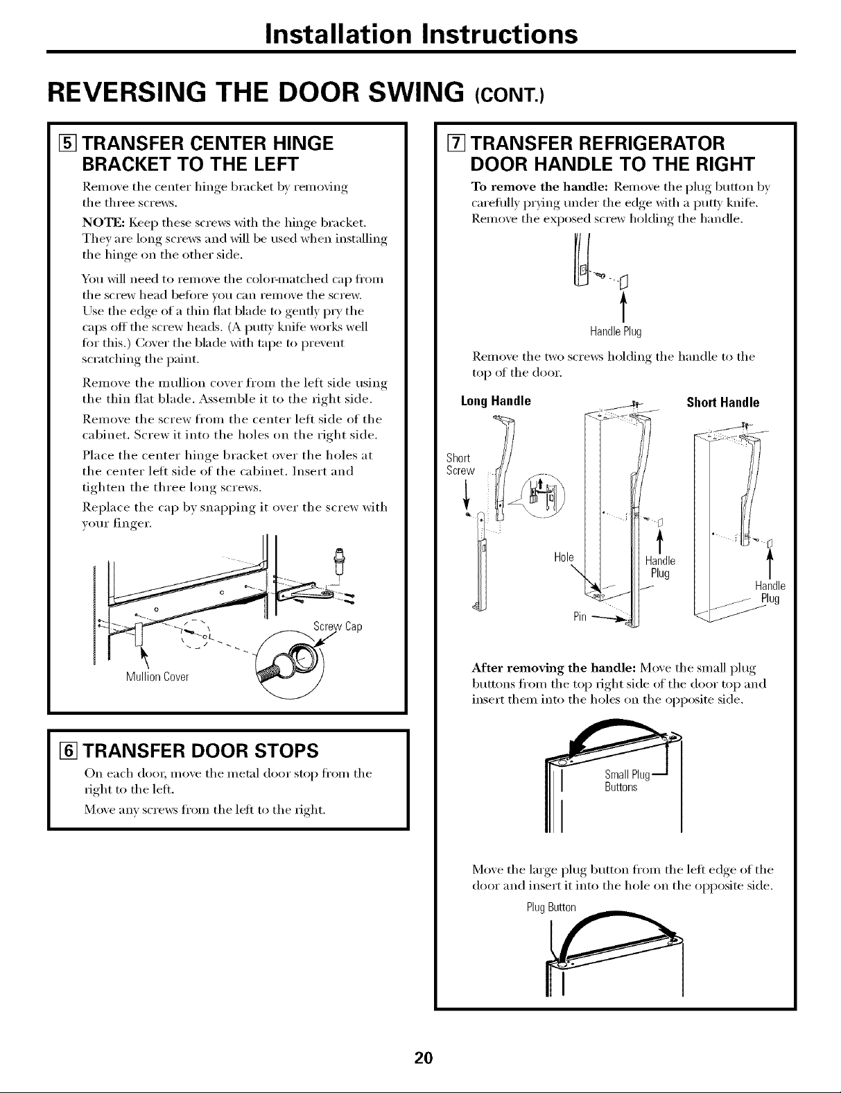
[] TRANSFER CENTER HINGE
BRACKET TO THE LEFT
]_.emove the center hinge bracket b.v removing
the three screws.
NOTE: Keep these screws with the hinge bracket.
They are long screws and will be used when installing
the hinge on the other side.
You will need to remove the colo>matched cap fl'om
the screw head befl)t'e volt c[lIl I'eIll(we the screw.
Use the edge of a thin flat blade to gently pry the
caps off the screw heads. (A put D' knite works well
fin" this.) Cover the blade with tape to prevent
scratching the paint.
Remove the mullion cover fl'om the left side using
the thin flat blade. Assemble it to the fight side.
Remove the screw fl'om the center left side of the
cabinet. Screw it into the holes on the right side.
Place the center hinge bracket ()vet" the holes at
the center left side of the cabinet. Insert and
tighten the three hmg screws.
Replace the cap by snapping it over the screw with
your finger.
[] TRANSFER REFRIGERATOR
DOOR HANDLE TO THE RIGHT
To remove the handle: Remove the I)lug button by
carefldly pr)_ng under the edge with a putt)' knife.
Remove the exposed screw holding the handle.
t
Handle Plug
Remoxe the two screws holding the handle to the
top of the door.
LongHandle
Short
Screw
ShortHandle
[] TRANSFER DOOR STOPS
On each door, mo_e the metal door stoi_ ti'om the
right to the left.
Moxe any screws fl'om the left to the right.
Hole Handle
\ Plug
Handle
Pin
After removing the handle: Move the small plug
buttons fl'om the top fight side of the door top and
insert them into the holes on the opposite side.
SmallPlu,
Buttons
Move the large, I)lu°,_ button fl'om the left edge of the
door and insert it into the hole on the opposite side.
PlugButton
2O

Installation Instructions
[] TRANSFER REFRIGERATOR DOOR
HANDLE TO THE RIGHT (CONT.)
Transfer the door I_lw"_button to the opposite side.
Butt
Reinstalling the handle: Attach the handle to the
fight side of the (loo_:
LongHandle
ShortHandle
f
Handle Hole
Plug
[] TRANSFER FREEZER DOOR
HANDLE TO THE RIGHT
Remo_e the screws holding the handle to the top and
bottom of the cloo_: Remoxe handle.
!x:!_g_____
"'22:22.,
Move the plug button on the right side (ff the door to
the handle screw hole on the left side.
Reattach the handle on the opposite side using the
holes closest to the edge of the doo_:
Pin
21
Installation Instructions
REVERSING THE DOOR SWING (CONT.)
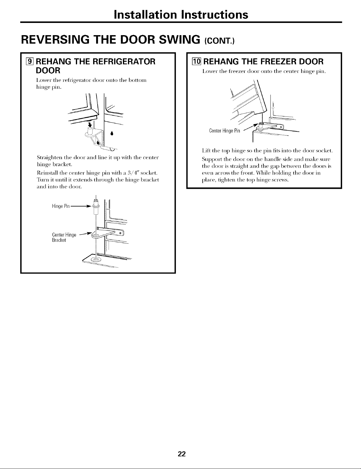
[] REHANG THE REFRIGERATOR
DOOR
I,ower tile I'etl]_eKKof door onto tile bottoil/
hinge pin.
6
-,__%_
Straighten the door and line it up with the center
hinge bracket.
Reinstall the center hinge pin with a 3/4" socket.
Turn it tmtil it extends through the hinge bracket
and into the door
L
CenterHinge
Bracket
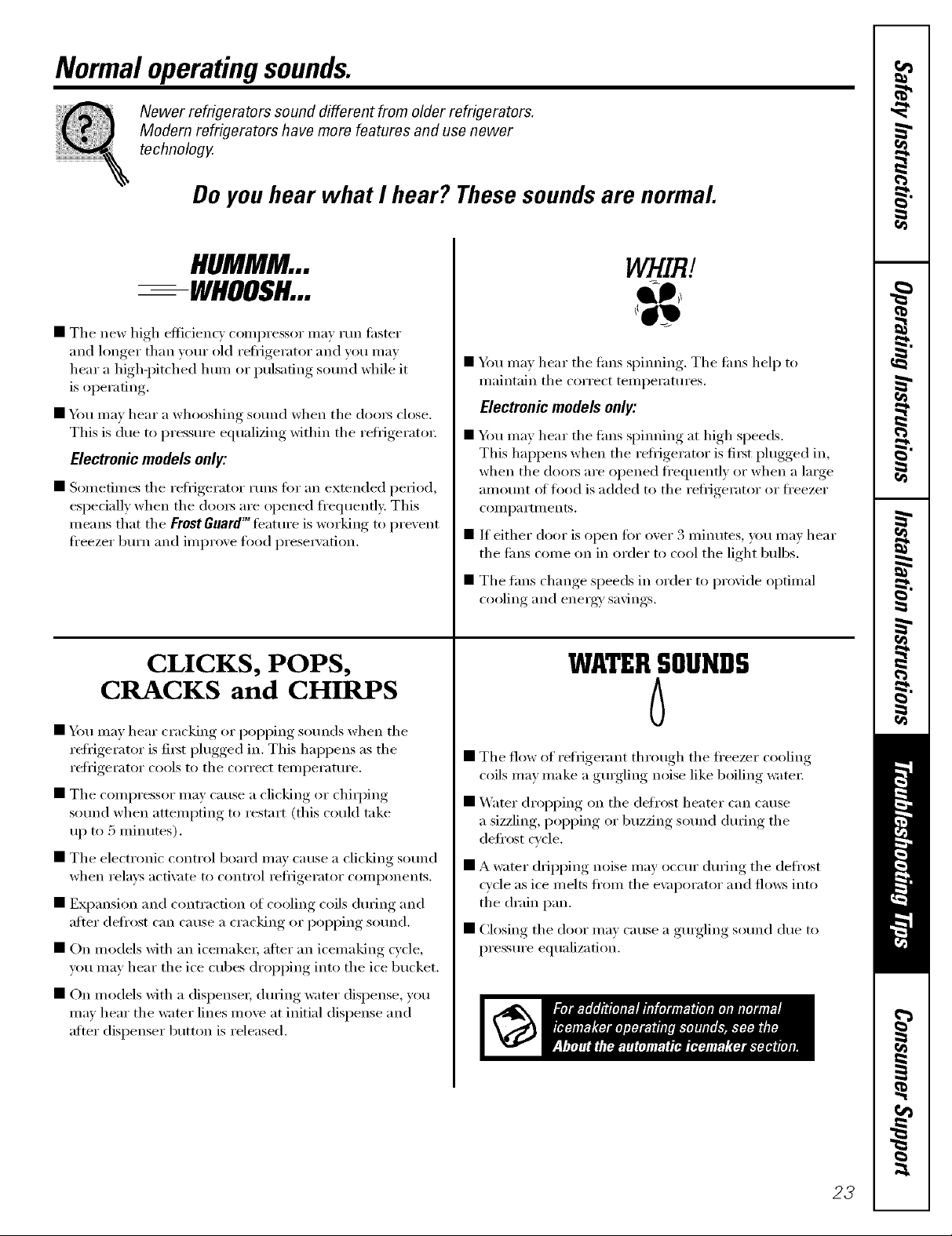
[] REHANG THE FREEZER DOOR
I,ower the ti'eezer door onto the center hinge pin.
CenterHingePin
i,ift the top hinge so the pin fits into the door socket.
Support the door on the handle side and make sure
the door is straight and the gap between the doors is
even across the fl'ont. \,_]file holding the door in
place, tighten the top hinge screws.
%
22
Normal operatingsounds.
Newer refrigerators sound different from older refrigerators.
Modem refrigerators have more features and use newer
technology.
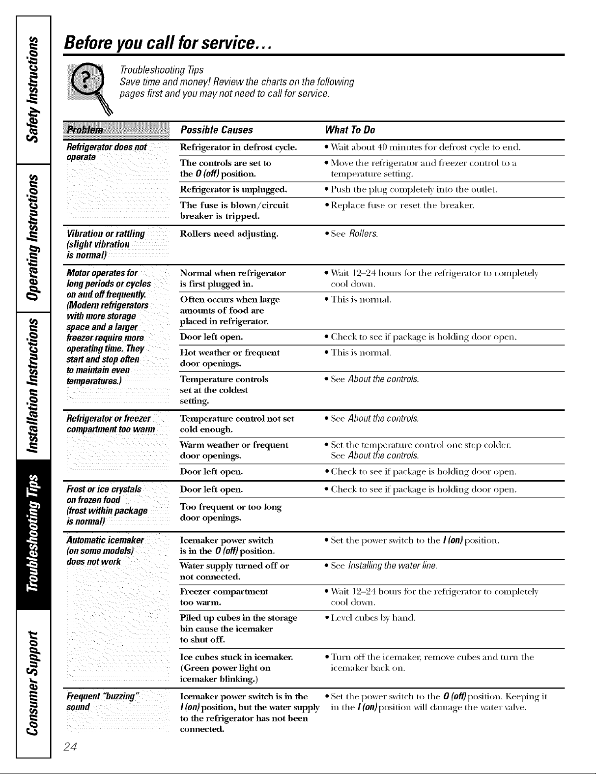
Do you hear what I hear? These sounds are normal.
HUMMM...
--WHOOSH...
• The new high efficiency compressor may run fi_ster
and longer than your old refi_igerator and you may
hear a high-l)itched hum or pulsating so/md while it
is operating.
• 54m may hear a whooshing so/md when the (loo_ close.
This is due to pressm'e equalizing within the reti_igerato_:
Electronic models only:
• Sometimes tile refl'igerator runs for an extended period,
espedally when tile doo_ are opened fl'equenfl): This
ineans that tile FrostGuardT"feature is working to prevent
fl'eezer burn and improve food l)rese_wation.
CLICKS, POPS,
CRACKS and CHIRPS
• _m may hear cracking or l)Ol)ping sotmds when tile
reti_igerator is fi_t l)lugged in. This hal)pens as tile
i'efiJgei'ator cools to tile coYi'ect teilll)ei'attli'e.
• Tile compressor may Catlse a clicking or chiq)ing
sound when attempting to restart (this could take
uI) to 5 minutes).
• The electronic control board may cause a clicking sotmd
when relays acti\me to control _efl_igerator components.
• EN)ansion and contraction of cooling coils during and
after defl'ost C_lll Catlse a ci'acking or l)Ol)ping soma&
• On models with an icemake_; after an icemaking cycle,
um may hear tile ice cubes dropping into tile ice bucket.
WHIRl
54m may hear tile rims 'IS)inning.* Tile rims hel I) to
maintain tile correct temperatm'es.
Electronic models only:
• Ybu may hear tile rims spinning at high speeds.
This hal)pens when tile refl_igerator is fiI_t plugged in,
when tile (loo_ are opened fl'equently or when a lmge
amotmt ot toed is added to the refl_igerator or fl'eezer
COIIll)_l i'tlilents.
• If either door is open tot over 3 minutes, you may hear
the tiros come on in order to cool the light bulbs.
• Tile rims change speeds in order to provide optimal
cooling and energy' savings.
WATERSOUNDS
6
• Tile flow of refrigerant through tile fl'eezer cooling
coils may make a gmgling noise like boiling water:
• Water dropping on tile defl'ost heater can cause
a sizzling, pol)ping or buzzing sotmd (lining tile
defl'ost cycle.
• A water dripping noise may occur during tile defl'ost
c)'cle as ice melts fl'om tile e\_q)orator and flo_vs into
tile drain pan.
• Closing tile door may cause a gmgling sotmd due to
pressm'e equalization.
• On models with a dispense_; dtwing water dispense, you
may hear tile water lines move at initial dispense and
after dispenser button is released,
23
Beforeyoucall forservice...
Troubleshooting -tips
Save time and money/. Review the charts on the following
pages first and you may not need to call for service.
Possible Causes What ToDo
Refrigerator does not Refrigerator in defrost cycle. * Wait about 40 ufinutes for defl'ost cycle to end.
The controls axe set to * Move the reflJgerator and fl'eezer control to a
theO(o.)pos tion. )e,.,,ue
Refrigerator is unplugged. * Push the plug completely into the oudet.
The fuse is blown/cireuit * Replace fllse or reset the breaker.
breaker is tripped.
Vibration orrattling Rollers need adjusting. * See Rollers.
(slight vibration
is normal)
Motor operates for Normal when refrigerator * "x._fit 12-24 houx_ fin" the reti_igerator to completely
long periods or cycles is first plugged in. cool down.
on and offfrequently.
(Modern refrigerators Often occurs when large * This is mmna[.
with more storage placed in refrigerator.
space and a larger
freezer require more Door left open. * Check to see it I)ackage, is holding door open.
operating time. They Hot weather or frequent * This is n(mnal.
staff and stop often door ope_mlgs.
tomaintain even
temperatures.) Temperature controls * See About the controls.
Refrigerator or freezer Temperature control not set • See About the controls.
Frost or ice crystals Door left open. * Check to see if I)ackage, is holding door open.
on frozen food
(frost within package Too frequent or too long
is normal) door ope_lhlgs.
mnotmts of food axe
set at the coldest
setting.
cold enough.
Warm weather or frequent * Set the temperature control one step col([e_:
door opetm,_. See Abouttho controls.
[ , •
if )ackaoe is holding door open.Door left open. * Check to see I
Automatic icemaker lcema.ker power switch * Set the power switch to the I(on) position.
(onsome models) is ha the 0 (off) position.
does not work Water supply turned off or * See Installing the water line.
not commcted.
Freezer compartment * _'%fit [2-24 l_otu_ fi)r the refl_igerator to completely
too warm. cool down.
Piled up cubes h:l the storage * I,e',el cubes by hand.
bin cause the icema_ker
to shut off.
Ice cubes stuck in icema_ker. * Ttlrn Off the icemake_; remoxe cubes and ttlrn the
(Green power light on icemaker back on.
icema_ker blinking.)
Frequent!'buzzing,
sound
lcema_ker power switch is in the
I (on) position, but the water supply
to the refrigerator has not been
commcted.
• Set the power switch to the 0 (off} position. Keelfin(*., it
in the I(OU)position will damage the water xdxe.
24
www.GEAppliances.com
Possible Causes What ToDo
Ice cubes have Ice storage bin needs clemlh_g. * Erupt) and wash bin. Discard old cubes.
odor/taste
Food trmlsmitthag odor/taste * Wrap fi)ocls well.
to ice cubes.
Interior of refrigerator * See Careand c/eaning.
needs clemlh_g.
Slow ice cube freezing Door left open. * Check to see it I)ackage, is holding door open.
Temperature control not set * See About the controls.
cold enough.
Noicecube Supply lh_e or shutoff * (:all a plumbex;
production valve is clogged.
Refrigerator has odor Foods trm_smitth_g * Foods with strong o(hn_ should be tightl) wrapped.
odor to refrigerator. * Keep an oI)en box of 1)aking, soda in the refl_gerator;
replace exerv three months.
Interior needs clemlh_g, * See Care and cleaning.
Moistnre collects inside Too frequent or too
(inhumidweather,air long door openings.
carriesmoistureinto
refrigerator when doors
are opened)
Interiotlightdoes No power at outlet. * ]_epla(e fuse or reset the breakei:
not work
HotaNfrombottom
Food freezing in Food too close to air vent. * Move the fi)od axvav fl'om the air xent (near the controls).
Doordoes Rollers need adjusting. * See Rollers.
by#self
Orange glowin Defrost heater is on. *This is n(mnal.
the freezer
Light bulb burned out. * See Replacingthelight bulbs.
Normal air flow cooling
motor. In the refrigeration
process, it is normaJ that
heat be expelled in the
area under the refrigerator.
Some floor coverings axe
sensitive and will discolor
at these nonnaJ and
safe temperatures.
Refrigerator control is set * Moxe the refl'igerator control to a wai'/ner temperature.
too cold.
25
Beforeyoucall forservice...
Troubleshooting -tips
Possible Causes What ToDo
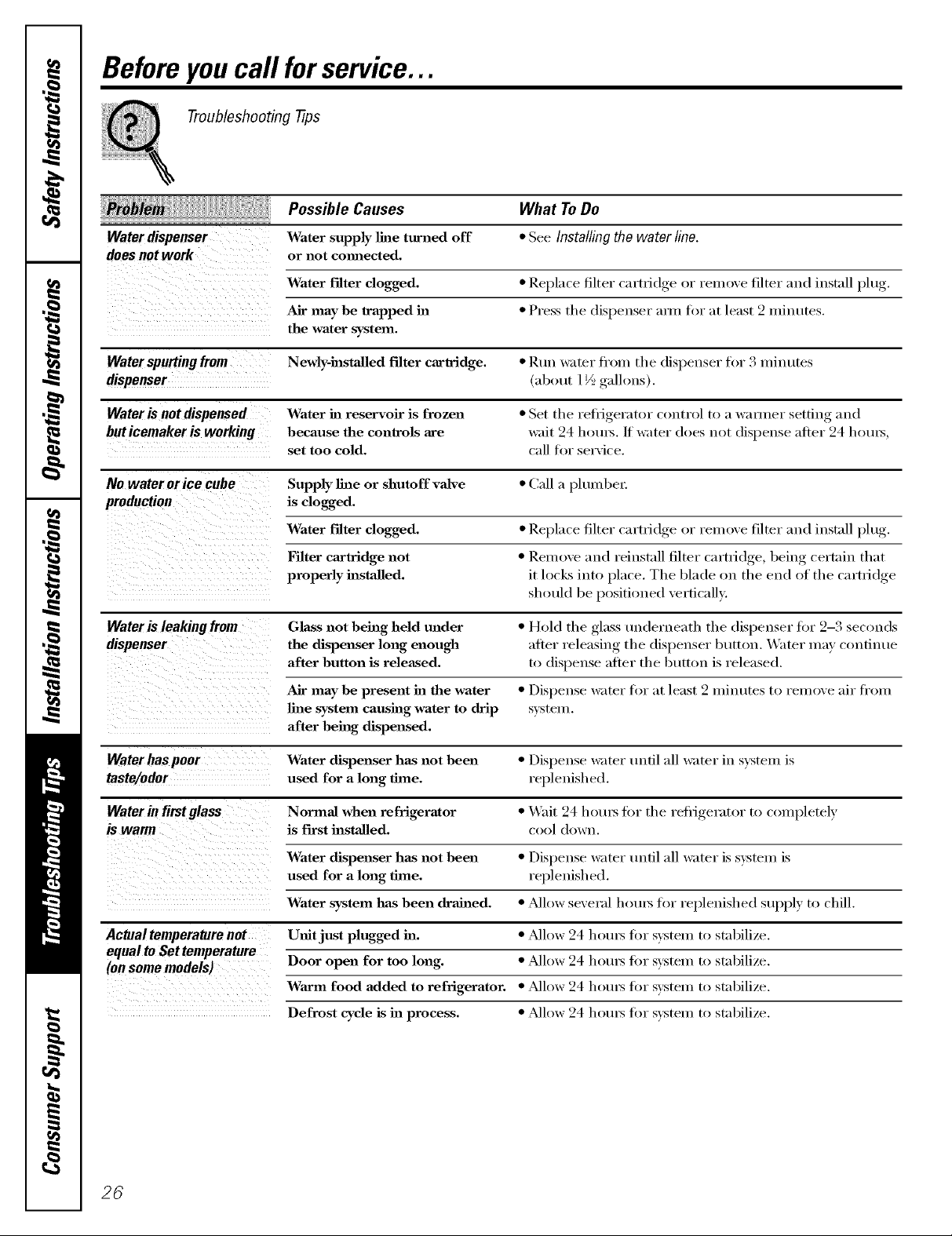
Water dispenser Water supply line turned off * See Installing the water line.
does not work or not cmmected.
Water filter clogged. * Replace filter ('artlJdge or l'elllOVe filter and install })lug7
Air may be trapped in * Press the dispenser ann fin" at lea,4 2 minutes.
the water system.
Water spurting from Newly-hastaUed filter cartridge. • I_.uu water h'om the dispenser for 3 minutes
dispenser (about 1½ galh)us).
Water is not dispensed Water in reservoir is frozen • Set the refrigerator control to a wanuer setting and
but icemaker is working because the controls are wait 24 horus./f water does not dispense after 24 hotn_,
set too cold. call for service.
No water orice cube Supply line or shutoff valve * Call a plumbe_:
production is clogged.
Water filter clogged. * Replace filter cartrid,,e_ or remove filter and install lflu_'
S • "
Filter cm'tridge not * Remove and reinstall, filter cartfidoe,_ behw_ certain that
properly hastaUed, it locks into place. The blade on the end of the cartYidge
should be positioned vertically.,
Water is leaking from Glass not being held under * Hold the glass underneath the dispenser fin" 2-3 sec_mds
dispenser the dispenser long enough after releasing the dispenser button. Water may continue
after button is released, to dispense after the butt_)n is released.
Air may be present ha the water • Dispense water tk)i" at least 2 minutes to remove air from
line system causing water to drip system.
after being dispensed.
Water has poor Water dispenser has not been * Dispense water tmfil :ill water in system is
taste/odor used for a long time. replenished.
Water in fimtglass Normal when refrigerator • Wait 24 hotu_ fin" the refi'igerator to completely
is first installed, c_l (h_wn.
Water dispenser has not been * Dispense water until :ill water is system is
used for a long time. replenished.
Water system has been drained. * _dh)w several horus for replenished supply to chill.
Actualtemperature not U_fit just plugged ha. * ?dlow 24 horns fin" s)'stem to stabilize.
equal to Set temperature
(on some models) Door open for too long. * ?dh _w 24 hotn_ fl n" system t() stabilize.
Wm-m food added to refrigerator. * _dlow 24 hotn_ fin" system to stabilize.
Defrost cycle is ha process. * _dlow 24 hotn_ fin" system to stabilize.
26
PerformanceData Sheet
SmartWaterFiltrationSystem
GSWF Cartridge
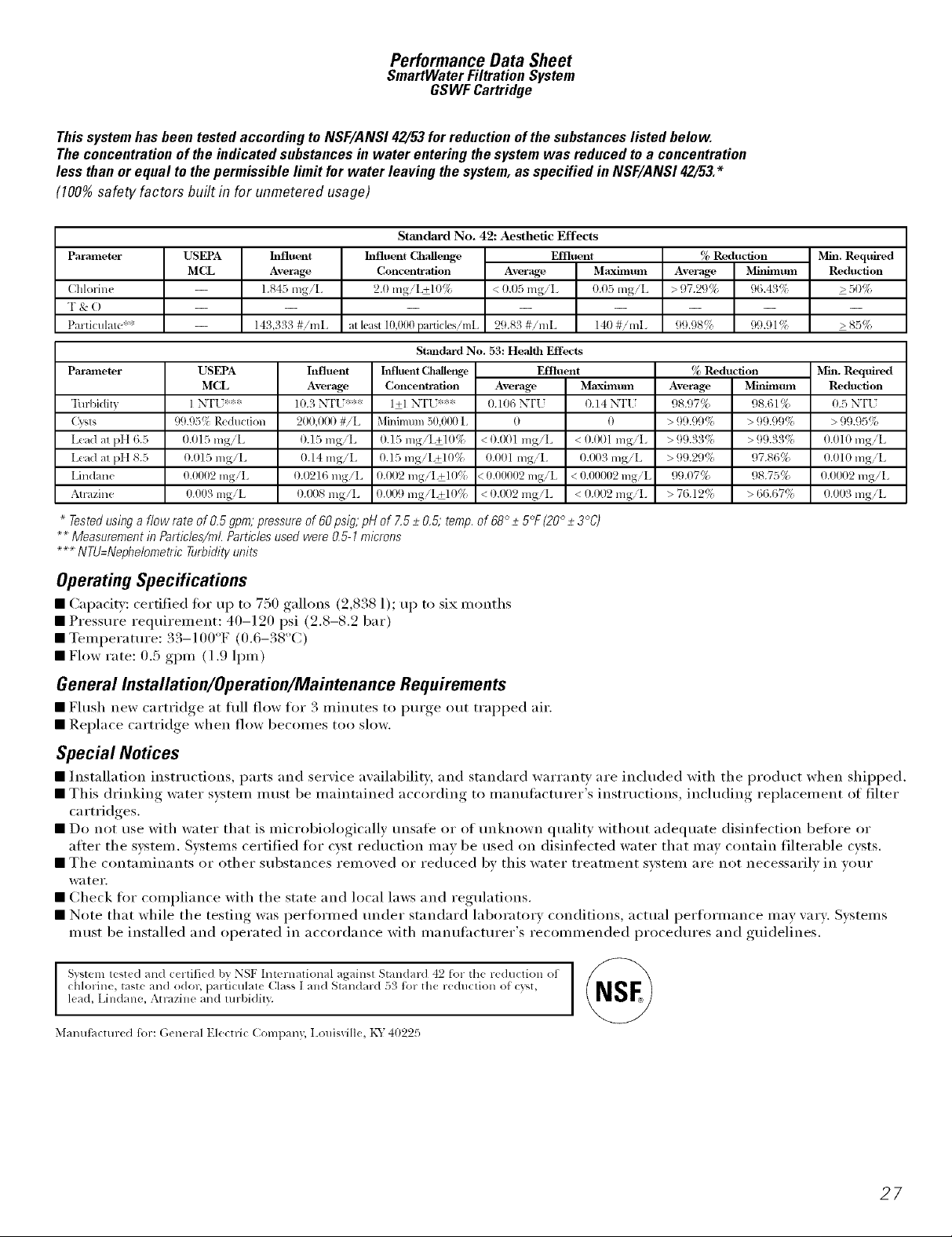
Thissystemhasbeen testedaccordingtoNSF/ANS142/53forreductionof thesubstanceslistedbelow.
Theconcentrationofthe indicatedsubstancesin water entering thesystemwas reducedto a concentration
less thanorequal tothepermissible limit for water leavingthesystem,as specified inNSF/ANS142/53.*
(100%safety factors built in for unmetered usage)
Standard No. 42: Aesthetic Effects
Parameter
(:hlorin(
T & ()
Particulale*':
Parameter
Turbidity
Cysts
I.ead aI pH 6.5
Lead aI pH 8.5
Lindane
A1F,izine
* Tested using a flow rate of O.5 gpm; pressure of 60 psig; pH of 7.5 _+O.5; temp. of 68° -+5°F (20° -+3°C)
** Measurement in Particles/ml. Particles used were 0,5-1 microns
*** NTU=Nephelometric Turbidity units
USEPA
MCL
USEPA
MCL
1 N'FU***
99.95% Reduction
0.015 mgiL
0.015 mgiL
0.0902 mgiL
9.007 mgiL
hlfluent
Average
1.845 mgiI.
143,333 #imI
19.3 N'F[ ;'::**
200,000 #iL
0.15 mgiL
0.14 mgiI
0.0216 mgiL
0.(X)8 mgiL
hafluent Challenge
2.9 mgiL+19%
at least 10,000pardcles/mL
Influent
Average
Concentration
Average MaxiIllttnl
< 0.05 mgiI. 0.05 mgiL
29.83 #imL 140 #imI.
Standard No. 53: Health Effects
Iilfhlent Clr,dlenge Effluent
Effluent
Concentration
1+1 N'[-[ :::**
Minimmn 50,0(X) 1,
O.15 mgiI.+l 0%
0.15 mgiL+10%
0.002 mgiI.+l 0!:_
0.1X)9 mgiL+l 0%
Average
0.106 _FI f
0
< 0.(R)I mgiL
0.001 mgiI.
<0.00002 mgiL
< 0.(_)2 mgiL
Maxirll [inl
0.14 NT[ ;
0
< 0.001 mgiI
0.(x)3 mgiL
< 0.00902 mgiL
< 0.002 mgiI.
% Reduction
Average Mitmnum
> _ 7.2_ % 96.43!'{
99.98!'_ 99.91%
_, Reduction
Average
98.97%
> 99.99!:{
> 99.33!:{
> 99.29!:i
99.t)7%
> 76.129{
Mha. Required
Reduction
> 50%
>85%
Min. Required
Mitfimtmi Reduction
98.61% 9.5 N'F[ ;
> 99.99!:{ > 99.95!:i
>99.33!:i 0.010 mgiL
97.86% 0.010 mgiL
98.75% 0.0(_)2 mgiL
> 66.67:1 0.003 mgiL
Operating Specifications
• (;apacity: certified ti)r up to 750 gallons (2,838 1); up to six months
• Pressttre requirement: 40-120 psi (2.8-8.2 bar)
• Telllperattlre: 33-100°F (0.6-38°(])
• Flow rate: 0.5 gpm (1.9 lpm)
General Installation/Operation/Maintenance Requirements
• Hush new cartridge, at full flow for .3 minutes to Imrge, out trapped air.
• Replace cartridge when flow becolnes too sh)w.
Special Notices
• Installation instructions, parts and service availability, and standard warranty are inchtded with the prodttct when shipped.
• This driI_king water s_steln inust be inaintained according to inanuf,lcturer's instructions, ii_chtding rel)lacelnent of filter
ca rtridges.
• Do not use with water that is microbiologically unsate or of unknown quality without adequate disinfection before or
atter the sx:steln. Svstelns certified tor cyst reduction inav be used on disinli_cted water that inay contain filterable cysts.
• The COlmmdlmnts or other substances relnoved or reduced by this water treatn/ent svsteln are not necessarily in wmr
water.
• Check for compliance with the state and local laws and regulations.
• Note that while the testing was l)ertiwlned under standard laboratory conditions, actual l)erfornmnce nlav vary. Svstelns
Inust be installed and operated in accordance with inanufilcturer's reconlnlended procedures and guidelines.
Svsteln lest(d an(1 c(rtifi((1 by NSF International agaillSl Standard 42 for th( r((h|ction of
chlorin(, tast( and odor, particular( Class ] a d S a ad, d :)_ for the reduclion of (:7,'st,
lead, Lindane, Atrazine and mrbidily.
3,Iant|factm-ed for: (;(neral Electri( (_ompany, I.ouisville, KY 40225
27
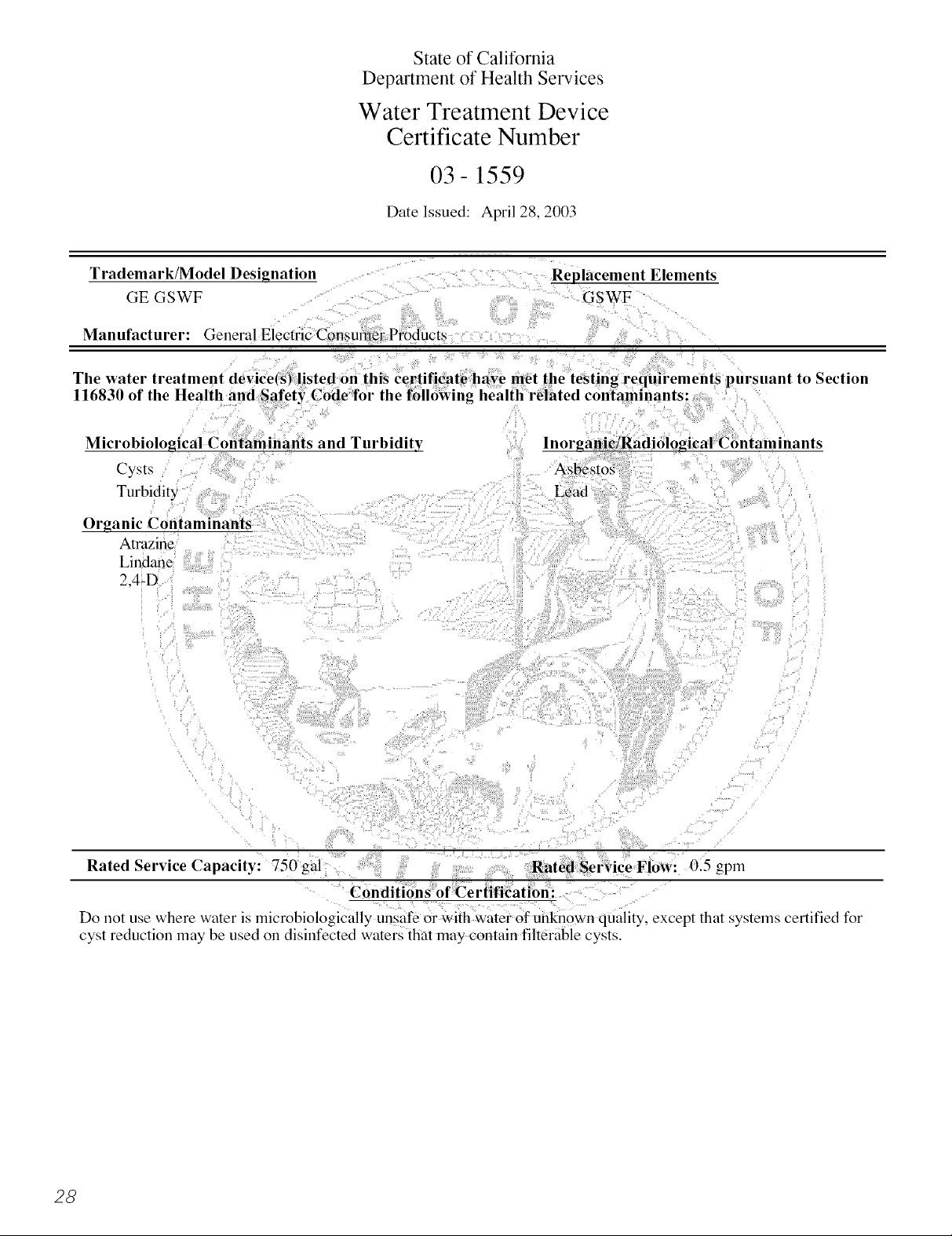
State of California
Department of Health Services
Water Treatment Device
Certificate Number
03-1559
Date Issued: April 28, 2003
Trademark/Model Designation
GE GSWF
Manufacturer: General Electric Consmner Products
Cysts
Turbidity
Organic Contaminants
Atrazine
Lindane
2,4-D
Replacement Elements
GSWF
to Section
lnorganic/Radiological Contaminants
Lead
Rated Service Capacity: 750 gal Rated Service Flow: 0.5 gpm
Conditions of Certification:
Do not use where water is microbiologically unsafe or with water of unknown quality, except that systems certified fbr
cyst reduction may be used on disinfected waters that may contain filterable cysts.
28
 Loading...