


PT878
Table of contents
 Loading...
GE
Sensing & Inspection Technologies Flow
TransPort® Model PT878
Portable Liquid Flowmeter
User’s Manual
910-219 Rev. F
November 2009


GE
Sensing & Inspection Technologies
TransPort® Model PT878
Portable Liquid Flowmeter
User’s Manual
910-219 Rev. F
November 2009
GESensingInspection.com
©2009 General Electric Company. All rights reserved.
Technical content subject to change without notice.

[no content intended for this page - proceed to next page]
ii

Preface
Information Paragraphs
• Note paragraphs provide information that provides a deeper understanding of
the situation, but is not essential to the proper completion of the instructions.
• Important paragraphs provide information that emphasizes instructions that
are essential to proper setup of the equipment. Failure to follow these
instructions carefully may cause unreliable performance.
• Caution! paragraphs provide information that alerts the operator to a hazardous
situation that can cause damage to property or equipment.
• Warning! paragraphs provide information that alerts the operator to a
hazardous situation that can cause injury to personnel. Cautionary information
is also included, when applicable.
Safety Issues
WARNING! It is the responsibility of the user to make sure all local, county,
state and national codes, regulations, rules and laws related to
safety and safe operating conditions are met for each
installation.
Transport® Model PT878 Portable Liquid Flowmeter User’s Manual iii

Preface
Auxiliary Equipment
Local Safety Standards
The user must make sure that he operates all auxiliary equipment in accordance
with local codes, standards, regulations, or laws applicable to safety.
Working Area
WARNING! Auxiliary equipment may have both manual and automatic
modes of operation. As equipment can move suddenly and
without warning, do not enter the work cell of this equipment
during automatic operation, and do not enter the work
envelope of this equipment during manual operation. If you do,
serious injury can result.
WARNING! Make sure that power to the auxiliary equipment is turned OFF
and locked out before you perform maintenance procedures on
the equipment.
Qualification of Personnel
Make sure that all personnel have manufacturer-approved training applicable to the
auxiliary equipment.
Personal Safety Equipment
Make sure that operators and maintenance personnel have all safety equipment
applicable to the auxiliary equipment. Examples include safety glasses, protective
headgear, safety shoes, etc.
Unauthorized Operation
Make sure that unauthorized personnel cannot gain access to the operation of the
equipment.
iv Transport® Model PT878 Portable Liquid Flowmeter User’s Manual

Preface
Environmental Compliance
Waste Electrical and Electronic Equipment (WEEE) Directive
GE Sensing & Inspection Technologies is an active participant in Europe’s
Waste Electrical and Electronic Equipment (WEEE) take-back initiative,
directive 2002/96/EC.
The equipment that you bought has required the extraction and use of
natural resources for its production. It may contain hazardous substances
that could impact health and the environment.
In order to avoid the dissemination of those substances in our environment
and to diminish the pressure on the natural resources, we encourage you to
use the appropriate take-back systems. Those systems will reuse or recycle
most of the materials of your end life equipment in a sound way.
The crossed-out wheeled bin symbol invites you to use those systems.
If you need more information on the collection, reuse and recycling
systems, please contact your local or regional waste administration.
Visit http://www.gesensing.com/environment/weee.htm
for take-back
instructions and more information about this initiative.
Transport® Model PT878 Portable Liquid Flowmeter User’s Manual v

Preface
[no content intended for this page - proceed to next page]
vi Transport® Model PT878 Portable Liquid Flowmeter User’s Manual

Contents
Chapter 1. Features and Capabilities
1.1 Overview . . . . . . . . . . . . . . . . . . . . . . . . . . . . . . . . . . . . . . . . . . . . . . . . . . . . . . . . . . . . . . .1
1.2 System Description . . . . . . . . . . . . . . . . . . . . . . . . . . . . . . . . . . . . . . . . . . . . . . . . . . . . .2
1.2.1 The Flowcell . . . . . . . . . . . . . . . . . . . . . . . . . . . . . . . . . . . . . . . . . . . . . . . . . . . . .2
1.2.2 Electronics Package. . . . . . . . . . . . . . . . . . . . . . . . . . . . . . . . . . . . . . . . . . . . . .3
1.3 Theory of Operation . . . . . . . . . . . . . . . . . . . . . . . . . . . . . . . . . . . . . . . . . . . . . . . . . . . .4
Chapter 2. Initial Setup
2.1 Making Electrical Connections. . . . . . . . . . . . . . . . . . . . . . . . . . . . . . . . . . . . . . . . . . .6
2.1.1 Power Connections . . . . . . . . . . . . . . . . . . . . . . . . . . . . . . . . . . . . . . . . . . . . . .7
2.1.2 Transducer Connections . . . . . . . . . . . . . . . . . . . . . . . . . . . . . . . . . . . . . . . . .7
2.1.3 Input/Output Connections. . . . . . . . . . . . . . . . . . . . . . . . . . . . . . . . . . . . . . . .7
2.1.4 The Infrared Wireless Interface . . . . . . . . . . . . . . . . . . . . . . . . . . . . . . . . . . .8
2.2 Caring for the PT878 Batteries. . . . . . . . . . . . . . . . . . . . . . . . . . . . . . . . . . . . . . . . . . .9
2.2.1 Charging and Storing the Batteries . . . . . . . . . . . . . . . . . . . . . . . . . . . . . . .9
2.2.2 Replacing the Batteries. . . . . . . . . . . . . . . . . . . . . . . . . . . . . . . . . . . . . . . . . 10
2.2.3 Disposing of Batteries. . . . . . . . . . . . . . . . . . . . . . . . . . . . . . . . . . . . . . . . . . 11
2.3 Powering ON and OFF . . . . . . . . . . . . . . . . . . . . . . . . . . . . . . . . . . . . . . . . . . . . . . . . 12
2.4 Using the Screen and Keypad . . . . . . . . . . . . . . . . . . . . . . . . . . . . . . . . . . . . . . . . . 15
2.4.1 Screen. . . . . . . . . . . . . . . . . . . . . . . . . . . . . . . . . . . . . . . . . . . . . . . . . . . . . . . . . 15
2.4.2 Keypad. . . . . . . . . . . . . . . . . . . . . . . . . . . . . . . . . . . . . . . . . . . . . . . . . . . . . . . . 17
2.5 Obtaining On-Line Help . . . . . . . . . . . . . . . . . . . . . . . . . . . . . . . . . . . . . . . . . . . . . . . 19
Transport® Model PT878 Portable Liquid Flowmeter User’s Manual vii

Contents
Chapter 3. Programming Site Data
3.1 Entering the Program Menu . . . . . . . . . . . . . . . . . . . . . . . . . . . . . . . . . . . . . . . . . . . 22
3.2 Entering Transducer Parameters . . . . . . . . . . . . . . . . . . . . . . . . . . . . . . . . . . . . . . 23
3.2.1 Parameters for Special Transducers . . . . . . . . . . . . . . . . . . . . . . . . . . . . 26
3.2.2 Confirming Entries . . . . . . . . . . . . . . . . . . . . . . . . . . . . . . . . . . . . . . . . . . . . . 30
3.3 Entering Pipe Parameters . . . . . . . . . . . . . . . . . . . . . . . . . . . . . . . . . . . . . . . . . . . . . 30
3.4 Entering Pipe Lining Parameters. . . . . . . . . . . . . . . . . . . . . . . . . . . . . . . . . . . . . . . 35
3.5 Entering Fluid Types and Speeds . . . . . . . . . . . . . . . . . . . . . . . . . . . . . . . . . . . . . . 37
3.6 Entering the Signal Path Parameters. . . . . . . . . . . . . . . . . . . . . . . . . . . . . . . . . . . 39
3.6.1 Path Parameters for Clamp-On Transducers . . . . . . . . . . . . . . . . . . . . 40
3.6.2 Path Parameters for Wetted Transducers . . . . . . . . . . . . . . . . . . . . . . . 41
3.7 Entering the Energy Option Parameters. . . . . . . . . . . . . . . . . . . . . . . . . . . . . . . . 42
3.7.1 Entering Inputs in the Energy Option . . . . . . . . . . . . . . . . . . . . . . . . . . . . 44
3.7.2 Entering Custom Cp Data in the Energy Option . . . . . . . . . . . . . . . . . . 46
3.8 Entering Analog Inputs. . . . . . . . . . . . . . . . . . . . . . . . . . . . . . . . . . . . . . . . . . . . . . . . 50
3.8.1 Entering General-Purpose Analog Inputs . . . . . . . . . . . . . . . . . . . . . . . . 50
3.8.2 Entering Analog Inputs in the Energy Option. . . . . . . . . . . . . . . . . . . . . 52
3.9 Entering the Analog Output . . . . . . . . . . . . . . . . . . . . . . . . . . . . . . . . . . . . . . . . . . . 54
3.10Entering the Digital Output . . . . . . . . . . . . . . . . . . . . . . . . . . . . . . . . . . . . . . . . . . . . 57
3.11Entering User Functions. . . . . . . . . . . . . . . . . . . . . . . . . . . . . . . . . . . . . . . . . . . . . . . 61
3.11.1 Entering Correction Factors. . . . . . . . . . . . . . . . . . . . . . . . . . . . . . . . . . . . . 65
3.11.2 Entering Reynolds Correction . . . . . . . . . . . . . . . . . . . . . . . . . . . . . . . . . . . 65
3.11.3 Entering a Calibration Factor . . . . . . . . . . . . . . . . . . . . . . . . . . . . . . . . . . . 67
viii Transport® Model PT878 Portable Liquid Flowmeter User’s Manual

Contents
Chapter 4. Creating and Managing Sites
4.1 The Site Manager . . . . . . . . . . . . . . . . . . . . . . . . . . . . . . . . . . . . . . . . . . . . . . . . . . . . . 72
4.1.1 Creating a New Site . . . . . . . . . . . . . . . . . . . . . . . . . . . . . . . . . . . . . . . . . . . . 74
4.1.2 Opening an Existing Site. . . . . . . . . . . . . . . . . . . . . . . . . . . . . . . . . . . . . . . . 76
4.1.3 Saving a Site. . . . . . . . . . . . . . . . . . . . . . . . . . . . . . . . . . . . . . . . . . . . . . . . . . . 77
4.1.4 Saving a Site with a Different Name. . . . . . . . . . . . . . . . . . . . . . . . . . . . . 78
4.1.5 Refreshing a Site . . . . . . . . . . . . . . . . . . . . . . . . . . . . . . . . . . . . . . . . . . . . . . . 79
4.1.6 Renaming a Site . . . . . . . . . . . . . . . . . . . . . . . . . . . . . . . . . . . . . . . . . . . . . . . 79
4.1.7 Deleting a Site . . . . . . . . . . . . . . . . . . . . . . . . . . . . . . . . . . . . . . . . . . . . . . . . . 80
4.1.8 Creating a Site Message. . . . . . . . . . . . . . . . . . . . . . . . . . . . . . . . . . . . . . . . 81
4.1.9 Printing a Current Site . . . . . . . . . . . . . . . . . . . . . . . . . . . . . . . . . . . . . . . . . . 83
4.1.10 Transferring a Site File to a PC . . . . . . . . . . . . . . . . . . . . . . . . . . . . . . . . . . 83
4.1.11 Transferring a Site File in Text Format to a PC . . . . . . . . . . . . . . . . . . . 84
4.1.12 Transferring a File from a PC to the PT878. . . . . . . . . . . . . . . . . . . . . . . 85
4.1.13 Listing Files by Name. . . . . . . . . . . . . . . . . . . . . . . . . . . . . . . . . . . . . . . . . . . 88
4.1.14 Listing Files in Chronological Order. . . . . . . . . . . . . . . . . . . . . . . . . . . . . . 88
Chapter 5. Displaying and Configuring Data
5.1 The Format Option. . . . . . . . . . . . . . . . . . . . . . . . . . . . . . . . . . . . . . . . . . . . . . . . . . . . 90
5.2 The View Option . . . . . . . . . . . . . . . . . . . . . . . . . . . . . . . . . . . . . . . . . . . . . . . . . . . . . . 92
5.3 The Limits Option . . . . . . . . . . . . . . . . . . . . . . . . . . . . . . . . . . . . . . . . . . . . . . . . . . . . . 93
5.4 The Measurement Option . . . . . . . . . . . . . . . . . . . . . . . . . . . . . . . . . . . . . . . . . . . . . 95
5.5 Customizing the Display Screen . . . . . . . . . . . . . . . . . . . . . . . . . . . . . . . . . . . . . . . 97
5.5.1 Specifying the Number of Displayed Parameters . . . . . . . . . . . . . . . . 98
5.5.2 Customizing Softkeys . . . . . . . . . . . . . . . . . . . . . . . . . . . . . . . . . . . . . . . . . . 99
5.6 Managing Files — The Drive Manager . . . . . . . . . . . . . . . . . . . . . . . . . . . . . . . . . 102
5.6.1 Transferring a File to a PC . . . . . . . . . . . . . . . . . . . . . . . . . . . . . . . . . . . . . 104
5.6.2 Transferring a File from a PC to the PT878. . . . . . . . . . . . . . . . . . . . . . 105
5.6.3 Refreshing a File . . . . . . . . . . . . . . . . . . . . . . . . . . . . . . . . . . . . . . . . . . . . . . 107
5.6.4 Deleting a File . . . . . . . . . . . . . . . . . . . . . . . . . . . . . . . . . . . . . . . . . . . . . . . . 108
5.6.5 Listing Files by Name. . . . . . . . . . . . . . . . . . . . . . . . . . . . . . . . . . . . . . . . . . 109
5.6.6 Listing Files in Chronological Order. . . . . . . . . . . . . . . . . . . . . . . . . . . . . 109
5.7 Accessing Meter Data —The About Option . . . . . . . . . . . . . . . . . . . . . . . . . . . . 110
Transport® Model PT878 Portable Liquid Flowmeter User’s Manual ix

Contents
Chapter 6. Programming Meter Settings
6.1 Entering the Meter Menu . . . . . . . . . . . . . . . . . . . . . . . . . . . . . . . . . . . . . . . . . . . . . 112
6.2 Selecting Measurement Units . . . . . . . . . . . . . . . . . . . . . . . . . . . . . . . . . . . . . . . . 113
6.3 The Battery Charger . . . . . . . . . . . . . . . . . . . . . . . . . . . . . . . . . . . . . . . . . . . . . . . . . 114
6.4 Entering Date and Time . . . . . . . . . . . . . . . . . . . . . . . . . . . . . . . . . . . . . . . . . . . . . . 115
6.5 Changing Date and Time Appearance . . . . . . . . . . . . . . . . . . . . . . . . . . . . . . . . 117
6.6 Adjusting the Contrast . . . . . . . . . . . . . . . . . . . . . . . . . . . . . . . . . . . . . . . . . . . . . . . 120
6.7 Setting Backlight Timeout . . . . . . . . . . . . . . . . . . . . . . . . . . . . . . . . . . . . . . . . . . . . 121
6.8 Changing the Display Language. . . . . . . . . . . . . . . . . . . . . . . . . . . . . . . . . . . . . . 122
6.9 Changing Communications Settings . . . . . . . . . . . . . . . . . . . . . . . . . . . . . . . . . . 123
6.10Resetting Forward and Reverse Totals . . . . . . . . . . . . . . . . . . . . . . . . . . . . . . . . 126
6.11Setting Up User Tables . . . . . . . . . . . . . . . . . . . . . . . . . . . . . . . . . . . . . . . . . . . . . . . 127
6.12Taking a Bitmap Capture of a Current Screen . . . . . . . . . . . . . . . . . . . . . . . . . 130
x Transport® Model PT878 Portable Liquid Flowmeter User’s Manual

Contents
Chapter 7. Logging Data
7.1 Entering the Logging Menu. . . . . . . . . . . . . . . . . . . . . . . . . . . . . . . . . . . . . . . . . . . 132
7.2 The Log Manager . . . . . . . . . . . . . . . . . . . . . . . . . . . . . . . . . . . . . . . . . . . . . . . . . . . . 133
7.3 The File Menu. . . . . . . . . . . . . . . . . . . . . . . . . . . . . . . . . . . . . . . . . . . . . . . . . . . . . . . . 134
7.3.1 Setting up a New Log . . . . . . . . . . . . . . . . . . . . . . . . . . . . . . . . . . . . . . . . . 135
7.3.2 Copying (Cloning) a Selected Log . . . . . . . . . . . . . . . . . . . . . . . . . . . . . . 140
7.3.3 Renaming a Log . . . . . . . . . . . . . . . . . . . . . . . . . . . . . . . . . . . . . . . . . . . . . . 141
7.3.4 Deleting a Log . . . . . . . . . . . . . . . . . . . . . . . . . . . . . . . . . . . . . . . . . . . . . . . . 141
7.3.5 Deleting All Logs . . . . . . . . . . . . . . . . . . . . . . . . . . . . . . . . . . . . . . . . . . . . . . 142
7.3.6 Refreshing the Log Manager Screen . . . . . . . . . . . . . . . . . . . . . . . . . . . 142
7.3.7 Printing a Log. . . . . . . . . . . . . . . . . . . . . . . . . . . . . . . . . . . . . . . . . . . . . . . . . 143
7.3.8 Transferring a Log to a PC. . . . . . . . . . . . . . . . . . . . . . . . . . . . . . . . . . . . . 144
7.4 The Log Menu . . . . . . . . . . . . . . . . . . . . . . . . . . . . . . . . . . . . . . . . . . . . . . . . . . . . . . . 145
7.4.1 Stopping (Pausing) a Log . . . . . . . . . . . . . . . . . . . . . . . . . . . . . . . . . . . . . . 146
7.4.2 Restarting a Log . . . . . . . . . . . . . . . . . . . . . . . . . . . . . . . . . . . . . . . . . . . . . . 146
7.4.3 Ending a Log. . . . . . . . . . . . . . . . . . . . . . . . . . . . . . . . . . . . . . . . . . . . . . . . . . 146
7.4.4 Stopping All Logs. . . . . . . . . . . . . . . . . . . . . . . . . . . . . . . . . . . . . . . . . . . . . . 147
7.4.5 Restarting All Logs . . . . . . . . . . . . . . . . . . . . . . . . . . . . . . . . . . . . . . . . . . . . 147
7.4.6 Ending All Logs . . . . . . . . . . . . . . . . . . . . . . . . . . . . . . . . . . . . . . . . . . . . . . . 147
7.4.7 View All Sites . . . . . . . . . . . . . . . . . . . . . . . . . . . . . . . . . . . . . . . . . . . . . . . . . 147
7.5 The View Menu . . . . . . . . . . . . . . . . . . . . . . . . . . . . . . . . . . . . . . . . . . . . . . . . . . . . . . 148
7.5.1 Displaying Log Details. . . . . . . . . . . . . . . . . . . . . . . . . . . . . . . . . . . . . . . . . 149
7.5.2 Displaying Log Data in Graphical Form. . . . . . . . . . . . . . . . . . . . . . . . . 150
7.5.3 Displaying Log Data in Spreadsheet Form . . . . . . . . . . . . . . . . . . . . . . 153
7.6 The Sort Menu . . . . . . . . . . . . . . . . . . . . . . . . . . . . . . . . . . . . . . . . . . . . . . . . . . . . . . . 154
7.6.1 Listing Logs by Name . . . . . . . . . . . . . . . . . . . . . . . . . . . . . . . . . . . . . . . . . 154
7.6.2 Listing Logs in Chronological Order . . . . . . . . . . . . . . . . . . . . . . . . . . . . 154
Transport® Model PT878 Portable Liquid Flowmeter User’s Manual xi

Contents
Chapter 8. Servicing the PT878
8.1 Entering the Service Menu . . . . . . . . . . . . . . . . . . . . . . . . . . . . . . . . . . . . . . . . . . . 156
8.2 Printing Reports . . . . . . . . . . . . . . . . . . . . . . . . . . . . . . . . . . . . . . . . . . . . . . . . . . . . . 157
8.3 Setting up the Thickness Gauge . . . . . . . . . . . . . . . . . . . . . . . . . . . . . . . . . . . . . . 159
8.4 Measuring Pipe Wall Thickness . . . . . . . . . . . . . . . . . . . . . . . . . . . . . . . . . . . . . . . 160
8.4.1 Entering the Material and Soundspeed. . . . . . . . . . . . . . . . . . . . . . . . . 160
8.4.2 Measuring Thickness in Numeric Format . . . . . . . . . . . . . . . . . . . . . . . 162
8.4.3 Displaying the Receive Signal in Graphical Format . . . . . . . . . . . . . . 163
8.4.4 Calibrating the Thickness Gauge Transducer . . . . . . . . . . . . . . . . . . . 165
8.4.5 Calculating Velocity (Pipe Material Soundspeed) . . . . . . . . . . . . . . . . 168
8.5 Programming the Thickness Gauge. . . . . . . . . . . . . . . . . . . . . . . . . . . . . . . . . . . 170
8.6 Displaying Diagnostic Parameters . . . . . . . . . . . . . . . . . . . . . . . . . . . . . . . . . . . . 173
8.7 Calibrating the Analog Output and Inputs . . . . . . . . . . . . . . . . . . . . . . . . . . . . . 174
8.7.1 Calibrating the Analog Output . . . . . . . . . . . . . . . . . . . . . . . . . . . . . . . . . 174
8.7.2 Calibrating Inputs . . . . . . . . . . . . . . . . . . . . . . . . . . . . . . . . . . . . . . . . . . . . . 176
8.8 Setting up Signal Parameters. . . . . . . . . . . . . . . . . . . . . . . . . . . . . . . . . . . . . . . . . 178
8.8.1 Setting up Signal Parameters . . . . . . . . . . . . . . . . . . . . . . . . . . . . . . . . . . 179
8.8.2 Setting up Peak Detection . . . . . . . . . . . . . . . . . . . . . . . . . . . . . . . . . . . . . 181
8.8.3 Selecting the Transmit Code. . . . . . . . . . . . . . . . . . . . . . . . . . . . . . . . . . . 183
8.9 Setting Error Limits. . . . . . . . . . . . . . . . . . . . . . . . . . . . . . . . . . . . . . . . . . . . . . . . . . . 184
8.10The Test Option . . . . . . . . . . . . . . . . . . . . . . . . . . . . . . . . . . . . . . . . . . . . . . . . . . . . . . 187
8.10.1 Testing the Screen . . . . . . . . . . . . . . . . . . . . . . . . . . . . . . . . . . . . . . . . . . . . 188
8.10.2 Testing the Keys . . . . . . . . . . . . . . . . . . . . . . . . . . . . . . . . . . . . . . . . . . . . . . 189
8.10.3 Testing the Watchdog Timer Circuit. . . . . . . . . . . . . . . . . . . . . . . . . . . . 190
8.10.4 Setting Impulse Response . . . . . . . . . . . . . . . . . . . . . . . . . . . . . . . . . . . . . 191
8.10.5 Taking Wave Samples for Diagnosis . . . . . . . . . . . . . . . . . . . . . . . . . . . 192
8.10.6 Applying a Stored Signal for Diagnosis . . . . . . . . . . . . . . . . . . . . . . . . . 192
8.10.7 Testing the Battery . . . . . . . . . . . . . . . . . . . . . . . . . . . . . . . . . . . . . . . . . . . . 193
8.11Resetting to Factory Default Parameters. . . . . . . . . . . . . . . . . . . . . . . . . . . . . . 194
8.12Updating PT878 Software . . . . . . . . . . . . . . . . . . . . . . . . . . . . . . . . . . . . . . . . . . . . 195
8.12.1 Updating Software Via IrOBEX . . . . . . . . . . . . . . . . . . . . . . . . . . . . . . . . . 196
8.12.2 Updating Software Via IrCOMM . . . . . . . . . . . . . . . . . . . . . . . . . . . . . . . . 197
xii Transport® Model PT878 Portable Liquid Flowmeter User’s Manual

Contents
Chapter 9. Diagnostics and Troubleshooting
9.1 Error Code Messages . . . . . . . . . . . . . . . . . . . . . . . . . . . . . . . . . . . . . . . . . . . . . . . . 204
9.2 Displaying Diagnostic Parameters . . . . . . . . . . . . . . . . . . . . . . . . . . . . . . . . . . . . 206
9.3 Flowcell Problems . . . . . . . . . . . . . . . . . . . . . . . . . . . . . . . . . . . . . . . . . . . . . . . . . . . 208
9.3.1 Fluid Problems . . . . . . . . . . . . . . . . . . . . . . . . . . . . . . . . . . . . . . . . . . . . . . . . 208
9.3.2 Pipe Problems . . . . . . . . . . . . . . . . . . . . . . . . . . . . . . . . . . . . . . . . . . . . . . . . 209
9.4 Transducer Problems . . . . . . . . . . . . . . . . . . . . . . . . . . . . . . . . . . . . . . . . . . . . . . . . 210
9.4.1 Wetted Transducer Problems. . . . . . . . . . . . . . . . . . . . . . . . . . . . . . . . . . 210
9.4.2 Clamp-on Transducer Problems . . . . . . . . . . . . . . . . . . . . . . . . . . . . . . . 211
9.4.3 Relocating Transducers . . . . . . . . . . . . . . . . . . . . . . . . . . . . . . . . . . . . . . . 212
Chapter 10. Specifications
10.1Overall . . . . . . . . . . . . . . . . . . . . . . . . . . . . . . . . . . . . . . . . . . . . . . . . . . . . . . . . . . . . . . 213
10.1.1 Hardware Configuration . . . . . . . . . . . . . . . . . . . . . . . . . . . . . . . . . . . . . . 213
10.1.2 Size/Weight. . . . . . . . . . . . . . . . . . . . . . . . . . . . . . . . . . . . . . . . . . . . . . . . . . . 213
10.1.3 Enclosure. . . . . . . . . . . . . . . . . . . . . . . . . . . . . . . . . . . . . . . . . . . . . . . . . . . . . 213
10.1.4 Flow Accuracy (Velocity, % of reading): . . . . . . . . . . . . . . . . . . . . . . . . . 213
10.2Electrical . . . . . . . . . . . . . . . . . . . . . . . . . . . . . . . . . . . . . . . . . . . . . . . . . . . . . . . . . . . . 214
10.3Operational Specifications . . . . . . . . . . . . . . . . . . . . . . . . . . . . . . . . . . . . . . . . . . . 216
10.4Transducer . . . . . . . . . . . . . . . . . . . . . . . . . . . . . . . . . . . . . . . . . . . . . . . . . . . . . . . . . . 217
10.4.1 Clamp-On Ultrasonic Flow Transducers . . . . . . . . . . . . . . . . . . . . . . . . 217
10.4.2 Temperature Transducers . . . . . . . . . . . . . . . . . . . . . . . . . . . . . . . . . . . . . 217
10.5Pipe Size and Material . . . . . . . . . . . . . . . . . . . . . . . . . . . . . . . . . . . . . . . . . . . . . . . 217
10.5.1 Clamp-On Transducers: . . . . . . . . . . . . . . . . . . . . . . . . . . . . . . . . . . . . . . . 217
10.6Available Options . . . . . . . . . . . . . . . . . . . . . . . . . . . . . . . . . . . . . . . . . . . . . . . . . . . . 218
Transport® Model PT878 Portable Liquid Flowmeter User’s Manual xiii

Contents
Appendix A. Menu Maps
Appendix B. Measuring P and L Dimensions
Appendix C. Temperature Transmitter Installation
C.1 Guidelines for RTD Installation. . . . . . . . . . . . . . . . . . . . . . . . . . . . . . . . . . . . . . . . 243
C.2 Mounting RTDs on the Pipe . . . . . . . . . . . . . . . . . . . . . . . . . . . . . . . . . . . . . . . . . . . 244
C.2.1 Assembling the Clamping Fixture . . . . . . . . . . . . . . . . . . . . . . . . . . . . . . 244
C.2.2 Mounting the RTD to the Pipe . . . . . . . . . . . . . . . . . . . . . . . . . . . . . . . . . . 245
C.3 Making Electrical Connections. . . . . . . . . . . . . . . . . . . . . . . . . . . . . . . . . . . . . . . . 245
C.3.1 Connecting the RTD to the 4 to 20-mA Transmitter . . . . . . . . . . . . . 246
C.3.2 Connecting the Transmitter to the PT878. . . . . . . . . . . . . . . . . . . . . . . 247
Appendix D. Ultrasonic Thickness Gauge Theory of Operation
D.1 Factors Affecting Performance and Accuracy . . . . . . . . . . . . . . . . . . . . . . . . . 250
D.1.1 Transducer Positioning/Alignment . . . . . . . . . . . . . . . . . . . . . . . . . . . . . 251
D.1.2 Calibration. . . . . . . . . . . . . . . . . . . . . . . . . . . . . . . . . . . . . . . . . . . . . . . . . . . . 252
D.1.3 Taper or Eccentricity . . . . . . . . . . . . . . . . . . . . . . . . . . . . . . . . . . . . . . . . . . 252
D.1.4 Acoustic Properties of the Material . . . . . . . . . . . . . . . . . . . . . . . . . . . . . 252
Appendix E. Material Safety Data Sheet for Couplant
E.1 Product Identification . . . . . . . . . . . . . . . . . . . . . . . . . . . . . . . . . . . . . . . . . . . . . . . . 253
E.2 Hazardous Ingredients . . . . . . . . . . . . . . . . . . . . . . . . . . . . . . . . . . . . . . . . . . . . . . . 253
E.3 Physical Data (nominal) . . . . . . . . . . . . . . . . . . . . . . . . . . . . . . . . . . . . . . . . . . . . . . 254
E.4 Fire and Explosion Hazard Data . . . . . . . . . . . . . . . . . . . . . . . . . . . . . . . . . . . . . . 254
E.5 Reactivity Data . . . . . . . . . . . . . . . . . . . . . . . . . . . . . . . . . . . . . . . . . . . . . . . . . . . . . . 254
E.6 Health Hazard and First Aid Data . . . . . . . . . . . . . . . . . . . . . . . . . . . . . . . . . . . . . 255
E.7 Storage and Handling Information. . . . . . . . . . . . . . . . . . . . . . . . . . . . . . . . . . . . 255
E.8 Control Measures . . . . . . . . . . . . . . . . . . . . . . . . . . . . . . . . . . . . . . . . . . . . . . . . . . . . 256
Appendix F. Establishing IR Communications
Appendix G. Glossary
xiv Transport® Model PT878 Portable Liquid Flowmeter User’s Manual

Chapter 1. Features and Capabilities
Chapter 1. Features and Capabilities
The TransPort® Model PT878 is a transit-time flowmeter which combines
all the features of a full-size flowmeter with the advantages of a portable
instrument.
This section describes the TransPort features and general system, and
explains the theory of operation.
1.1 Overview
The PT878 measures the flow rate of acoustically conductive single-phase
fluids. This includes most clean liquids, sewage, some slurries, some
oil/water mixtures, and liquids with a small percentage of entrained gas
bubbles. The flowmeter provides one linear (0/4-20 mA) analog output of
flow velocities or volumetric flow rate of these fluids, measuring velocities
from ±0.03 to ±12 m/sec (±0.1 to ±40 ft/sec), along with one selectable
frequency output or pulsed totalizer output.
The PT878 also provides two 4 to 20-mA analog inputs in order to connect
temperature transmitters to measure energy flow rate of liquids. Energy
flow rate may be calculated for water, glycol, and water/glycol mixtures.
The PT878 has the ability to store site data in files which can be accessed at
a later time. Within the Main Menu, a set of forms (windows) asks you all
the necessary setup information for a particular site. Once the necessary
questions are answered, you simply save the information to a file.
The PT878 stores these files and other data in non-volatile memory, which
retains the information even if power is off. The flowmeter itself runs on
rechargeable or alkaline batteries for up to 10 hours.
This small lightweight flowmeter displays measurements in both numeric
and graphical form on a EL-backlit, 240 x 200 pixel LCD graphic screen.
The PT878 also has the capability of logging over 100,000 flow data points
internally.
Using an infrared communications port, the PT878 can transmit or print
logged data, as well as real time data and other stored data. It is also
computer-programmable via GE’s PanaView™ software.
Transport® Model PT878 Portable Liquid Flowmeter User’s Manual 1

Chapter 1. Features and Capabilities
1.1 Overview (cont.)
To assist you, the PT878 is fully equipped with context-sensitive on-line
help which is accessible at any time by simply pressing the “?” (Help) key.
Internal diagnostic and troubleshooting features help is olate and remedy
common flowcell and transducer problems.
The PT878 operates with all standard GE transducers - wetted, clamp-on,
®
hybrids (Pan-Adapta
plug), and buffered styles.
A built-in ultrasonic thickness gauge capability measures the pipe wall
thickness when used with the optional thickness transducer.
1.2 System Description
The PT878 is one part of the flowmeter system. The flowmeter system
consists of two essential subsystems: the flowcell and the electronics
package (the PT878).
1.2.1 The Flowcell
The flowcell is that part of the system that uses ultrasonic pulses to
interrogate the flow. It consists of the flowcell pipe and the transducers.
A. FLOWCELL PIPE - The flowcell can either be created in the existing
piping (for example, by inserting wetted transducers into the pipe, or
clamping non-wetted transducers onto the pipe), or inserted as a
substitute pipe section (spoolpiece). The flowcell must provide
mechanical support for the transducers and assure stable fluid conditions
for accurate flow measurement.
B. TRANSDUCERS - The transducers convert electrical energy into
ultrasonic pulses when in a transmit cycle, and convert the ultrasonic
pulses back to electrical energy when in a receive cycle. In other words,
they act like loudspeakers when transmitting the signal and microphones
when receiving it. In the PT878 system, each transducer acts as both a
receiver and transmitter, since a series of ultrasonic pulses are alternately
sent upstream and then downstream through the flowcell.
2 Transport® Model PT878 Portable Liquid Flowmeter User’s Manual

Chapter 1. Features and Capabilities
1.2.2 Electronics Package
The PT878 consists of circuits that generate, receive, and measure the travel
time of the ultrasonic pulses. It also contains a microcomputer that controls
operation and calculates flow measurement parameters. Specific circuits
function as follows:
• TRANSMIT SIGNAL GENERATOR - The transmit signal generator,
under control of the microcomputer and timing circuit, synthesizes the
signal that drives the transmitter.
• TRANSMITTER - The transmitter amplifies the signals from the
transmit signal generator to a signal that drives the transmit transducer.
• RECEIVER - The receiver amplifies the received signals to a level
suitable for the data acquisition circuitry.
• DATA ACQUISITION - The data acquisition circuitry digitizes the
received signal and stores it in a buffer for processing by the
microcomputer.
• TIMING CIRCUIT - The timing circuit generates the transmitter
frequency, receive window, controls the data acquisition circuit and the
direction of the transmission.
• MICROCOMPUTER - The microcomputer controls the PT878
flowmeter’s operation and calculates flow measurements derived from
the transmitted and digitized received signals. Also, the microcomputer
continually checks for faults and allows the use of built-in diagnostics for
troubleshooting.
• INPUT/OUTPUT - The input/output circuitry allows the flowmeter to
indicate the measured flow with the 0/4-20 mA current loop, and to
output to a printer or other remote device. The digital output supports
frequency or pulse output, as well as use as a gate input; it can also act as
a test point for triggering an oscilloscope from the transmit or receive
window.
Transport® Model PT878 Portable Liquid Flowmeter User’s Manual 3

Chapter 1. Features and Capabilities
1.3 Theory of Operation
The PT878 is a transit-time ultrasonic flowmeter. When ultrasonic pulses
are transmitted through a moving liquid, the pulses that travel in the same
direction as the fluid flow (downstream) travel slightly faster than the pulses
that travel against the flow (upstream). The PT878 uses various digital
signal processing techniques, including cross-correlation, to determine
transit times and then uses the transit times to calculate flow velocity.
During operation, two transducers serve as both ultrasonic signal generators
and receivers. When mounted on a pipe, they are in acoustic communication
with each other, so that each transducer can receive ultrasonic signals
transmitted by the other transducer. Each transducer thus functions as a
transmitter generating a certain number of acoustic pulses, and as a receiver
for an identical number of pulses.
The flowmeter measures the time interval between transmission and
reception of the ultrasonic signals in both directions. When the liquid in the
pipe is not flowing, the transit-time downstream equals the transit-time
upstream. When the liquid is flowing, the transit-time downstream is less
than the transit-time upstream. The difference between the downstream and
upstream transit-times is proportional to the velocity of the flowing liquid,
and its sign indicates the direction of flow.
4 Transport® Model PT878 Portable Liquid Flowmeter User’s Manual
Chapter 2. Initial Setup
Chapter 2. Initial Setup
Before making measurements, you must prepare the PT878 for operation.
This includes the following procedures:
• Making Electrical Connections
• Charging and/or Replacing Batteries
• Powering On and Off
• Using the Screen and Keypad
• Obtaining On-Line Help
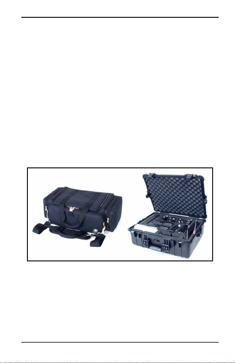
Figure 1 below shows the PT878 in its standard soft case (a) and in the
optional solid case (b). In the solid case, the interior is structured for optimal
protection of the PT878 and its accessories.
(a) (b)
Figure 1: The PT878 and Accessories
Transport® Model PT878 Portable Liquid Flowmeter User’s Manual 5
Chapter 2. Initial Setup
2.1 Making Electrical Connections
Before making measurements with the PT878, you must make all the
necessary connections to the unit. This section describes how to connect the
following:
• Power
• Transducers
• Input/Output
• Infrared Interface
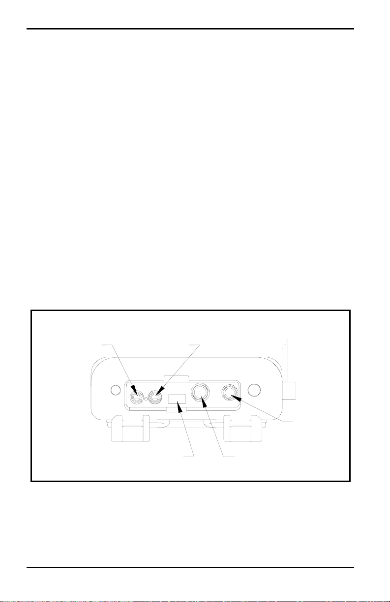
Make all connections to the top of the PT878 unit as shown in Figure 2
below. Please note that you need to make the proper power and transducer
connections only. The other connections are required for particular
functions, but are not necessary for basic operation.
Note: For a listing of Input/Output connections, see Table 1 on page 8.
Transducer
Upstream
Infrared Transceiver
Downstream
Power
Input/Output
Figure 2: Connection Locations
6 Transport® Model PT878 Portable Liquid Flowmeter User’s Manual

Chapter 2. Initial Setup
2.1.1 Power Connections
The PT878 is powered by either a 100-120/200-260 VAC wall mount
plug-in module, or by 5 internal C
-size NiCad high-energy rechargeable
s
batteries or by a pack of 3.0 Ahr NiMH batteries. (An optional power
supplement, part #703-1283, uses 6 AA alkaline batteries.) When you
receive the PT878, the batteries are not charged; therefore, to make remote
measurements using the batteries, follow the instructions on page 9 to
charge the batteries. In either case, you must connect the power cord to the
appropriate terminal as shown in Figure 2 on page 6.
WARNING! To ensure the safe operation of the PT878, you must
install and operate it as described in this manual. In
addition, be sure to follow all applicable safety codes and
regulations for installing electrical equipment in your
area. The PT878 and its transducers are designed for use
only in general-purpose locations.
2.1.2 Transducer Connections
The transducer cables connect to the PT878 with LEMO® coaxial type
connectors. Each color-coded cable should have a collar labeled
UPSTREAM or DOWNSTREAM. Make transducer cable connections to
the top of the flowmeter as shown in Figure 2 on page 6. Because there are
various types of transducers and installations, transducer installation is
discussed separately in the Liquid Transducer Installation Guide (916-055).
2.1.3 Input/Output Connections
The PT878 provides one 0/4-20 mA current output and two 4 to 20-mA
analog inputs with switchable 16-V supply for loop- powered temperature
transmitters. It also supports digital, frequency, and totalizer outputs.
Connect the inputs/outputs using a LEMO
Figure 2 on page 6. The pin numbers for the connector and the color code
for the standard input/output cable are shown in Table 1 on page 8.
Transport® Model PT878 Portable Liquid Flowmeter User’s Manual 7
®
multi-pin connector as in

Chapter 2. Initial Setup
2.1.3 Input/Output Connections (cont.)
Table 1: Cable Assembly for Analog Inputs/Outputs
Pin
Number
Wire
Color Description
1 Black Analog Out 1
2 Red 16 V (switched)
3 White Supply or Return Temperature (Input A)
4 Yellow Supply or Return Temperature (Input B)
5 Green Analog Ground
6 Orange Digital Output (frequency output, pulse totalizer,
diagnostic output or calibration gate)
7 Blue Digital Ground
8 Violet Receive Monitor
2.1.4 The Infrared Wireless Interface
The PT878 comes equipped with an internal infrared transceiver (shown in
Figure 2 on page 6) that enables communication between the meter and
other IR devices, particularly the IR ports or dongles (IR to RS232 adapters)
of Windows
They can also program the meter using the optional PanaView software
interface. The PT878 was designed for use with products that comply to the
IrDA protocol. For more information on establishing IR communications
between the PT878 and your PC, refer to Appendix F.
®
-based PCs. Users can send and receive site and log data.
Note: The dongle connection is RS232. The configuration options are either
RS232 or IRDa. Selecting the RS232 does not
link the meter to the
dongle. IrDa must be selected for the link to work.
• To transfer files between the PT878 and PC, see Managing Files — the
Drive Manager on page 102.
• To transfer a log from the PT878 to a PC, see page 144.
8 Transport® Model PT878 Portable Liquid Flowmeter User’s Manual

Chapter 2. Initial Setup
2.2 Caring for the PT878 Batteries
The PT878 comes with self-contained, built-in rechargeable batteries to
support portable operation. For optimum performance, these batteries
require a minimum of maintenance.
CAUTION! Use only GE-approved batteries and desktop chargers.
These chargers are designed to maximize battery life.
Using other batteries or chargers voids the warranty and
may cause damage.
IMPORTANT: For CE compliance, the PT878 is classified as a
battery-powered device, not to be used with the AC
adaptor.
2.2.1 Charging and Storing the Batteries
When you receive the PT878, you will need to initially charge the batteries.
Also, the battery may need recharging if it has not been used for a long
period of time. The batteries must be charged up to 8 hours to receive the
maximum charge. When fully charged, the batteries provide 8 to 10 hours
of continuous operation. An internal battery gauge indicates the remaining
power in the batteries.
To charge the batteries, simply plug the AC power module cord into the
power jack (shown in Figure 2 on page 6) and be sure the battery pack is
installed. When the PT878 is plugged into line voltage, the internal battery
charger automatically charges the batteries, whether the PT878 is on or off.
If the PT878 is on, the Battery icon in the upper right corner of the screen
indicates battery status (as shown in Table 2 on page 10).
Note: For version 1B of the PT878 software, you must also press the red
power key in the upper right corner of the keypad. (See page 110 to
determine your software version.)
For optimal run time, charge the batteries only in temperatures from 50°F to
104°F (10°C to 40°C). Otherwise, the batteries will not be properly charged
and will have a significantly reduced run time.
Transport® Model PT878 Portable Liquid Flowmeter User’s Manual 9
Chapter 2. Initial Setup
2.2.1 Charging and Storing the Batteries (cont.)
Store the batteries at temperatures from –4°F to 131°F (–20°C to 55°C) for
periods of less than one month, or from 32°F to 104°F (0°C to 40°C) for
longer periods. (If you are transporting them for two days or less, the
batteries can withstand temperatures from –40°F to 158°F (–40°C to 70°C).
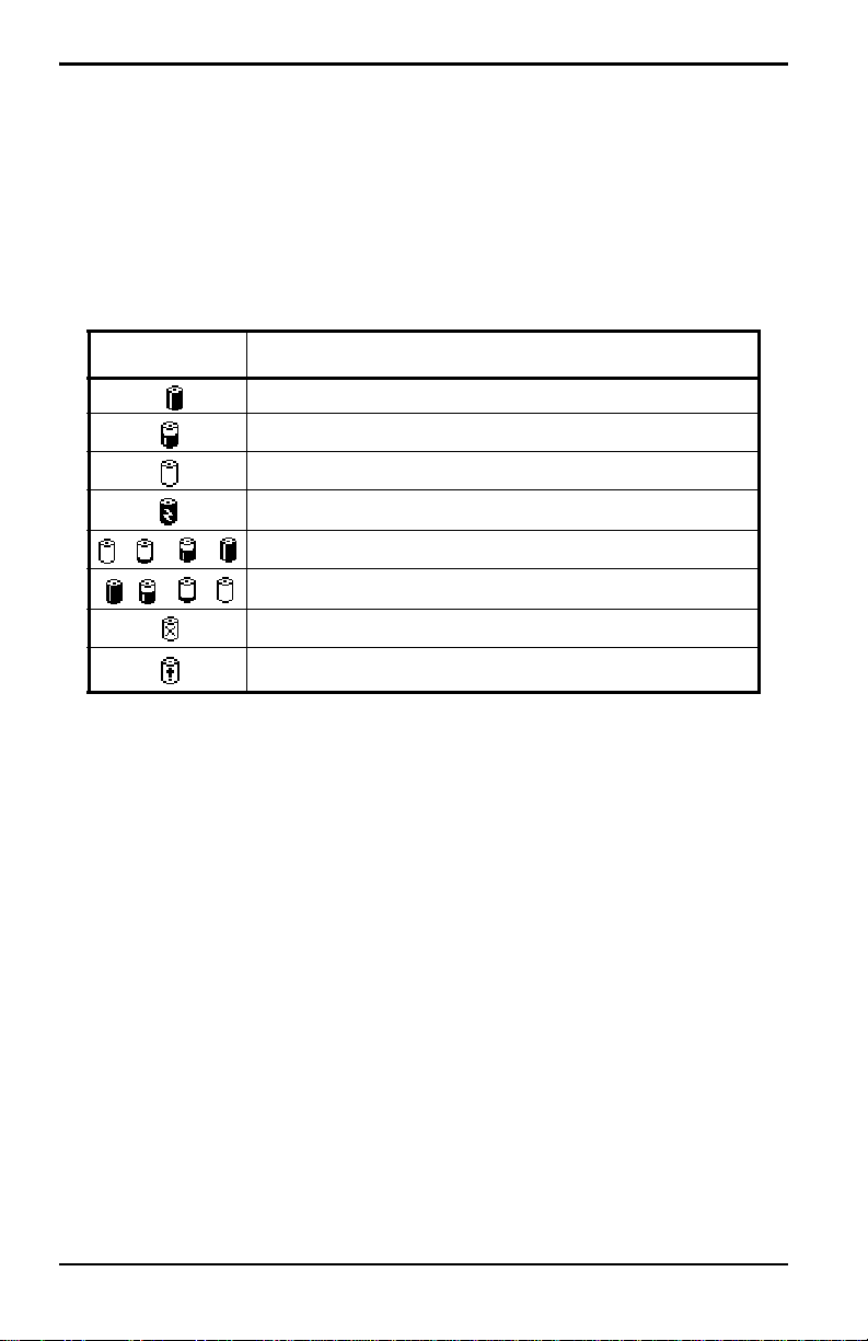
Table 2: Battery Status Icons
Icon Battery Status
Full battery
Partially full battery
Empty battery
Fully charged battery, connected to AC power
Charging battery
Discharging battery
Failure/missing battery
Notification to check battery form (see page 114)
2.2.2 Replacing the Batteries
CAUTION! Replace batteries only with the specified rechargeable
batteries. The battery charges when the unit is off. Do not
attempt to recharge non-rechargeable batteries.
If you need to replace the rechargeable batteries, use the recommended 3.0
Ahr NiMH batteries (part number 200-081). While the batteries can be
recharged up to 600 times, it is best to replace them when they no longer
provide acceptable performance. T o replace the batteries, remove the rubber
boot, open the panel located on the back of the PT878 unit, disconnect the
batteries, and replace with new ones (see Figure 3 on page 11).
10 Transport® Model PT878 Portable Liquid Flowmeter User’s Manual
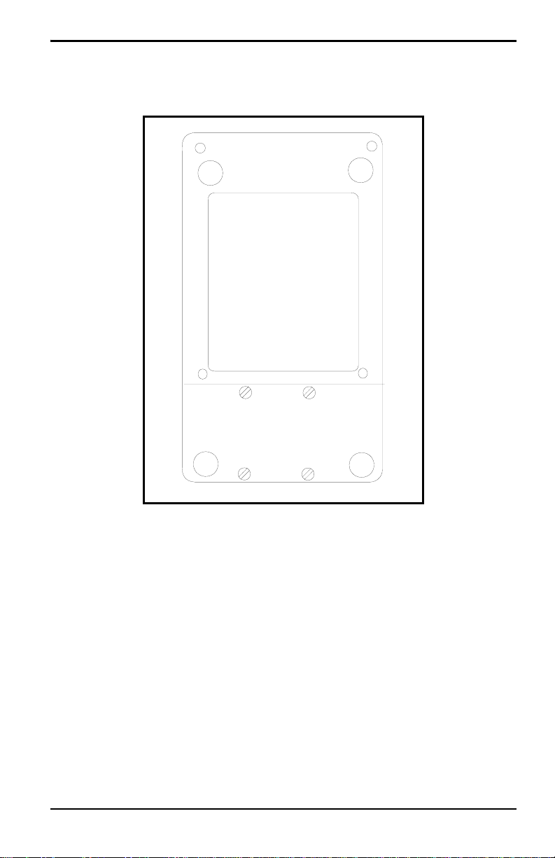
2.2.2 Replacing the Batteries (cont.)
Battery Location
(behind panel)
Chapter 2. Initial Setup
Figure 3: Battery Location
To further extend the battery power on the PT878, the GE Part #705-1283
option uses 6 AA alkaline batteries.
2.2.3 Disposing of Batteries
CAUTION! Never dispose of the batteries by incineration. Do not
attempt to disassemble or short-circuit the batteries. For
safety. do not handle a damaged or leaking battery.
IMPORTANT: Be sure to dispose of your battery properly. In some areas,
battery disposal in business or household trash may be
prohibited. For safe disposal options, contact your nearest
GE-authorized service center.
Transport® Model PT878 Portable Liquid Flowmeter User’s Manual 11

Chapter 2. Initial Setup
2.3 Powering ON and OFF
To operate the PT878, the power cord must be plugged into line voltage or
the battery must be charged as described previously.
IMPORTANT: For CE compliance, the PT878 is classified as a
battery-powered device, not to be used with the AC adapter.
To comply with CE certification, do not operate the meter
with the charger plugged in.
T o turn the PT878 on, press the red button in the upper-right-hand corner of
the keypad. Immediately upon power up the PT878 emits a short beep and
displays a “PCI Loader” message. It then validates the instrument
programming, and then displays the GE logo and the software version and
emits a long beep. If the meter fails any of these tests, contact the factory.
WARNING! If the meter fails the backup battery test, you must send
the unit back to the factory for a battery replacement.
Make sure you keep the batteries charged until you are
ready to ship the unit back to the factory. Before shipping,
print out all the log and site data, or transfer it to your PC.
12 Transport® Model PT878 Portable Liquid Flowmeter User’s Manual
Chapter 2. Initial Setup
2.3 Powering ON and OFF (cont.)
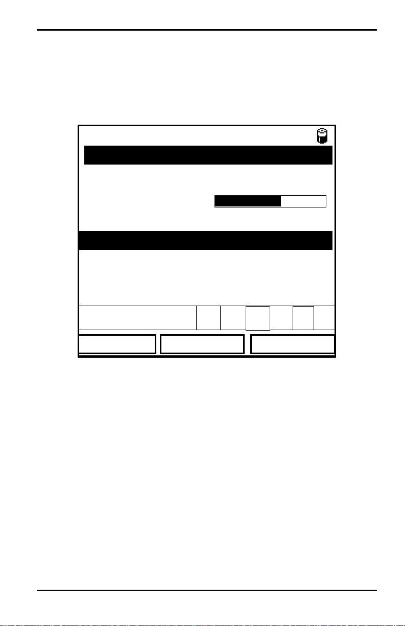
After the meter conducts all the self checks, the screen then appears similar
to the one shown in Figure 4 below.
ABC.SIT
Velocity, ft/s
0.00
Delta-T, ns
E0: No Errors
Figure 4: Screen After Powering ON
0.10
2000/11/30 09:53 AM
Signal, dB
32
Volume, l/s
0.0
Transport® Model PT878 Portable Liquid Flowmeter User’s Manual 13
Chapter 2. Initial Setup
2.3 Powering ON and OFF (cont.)
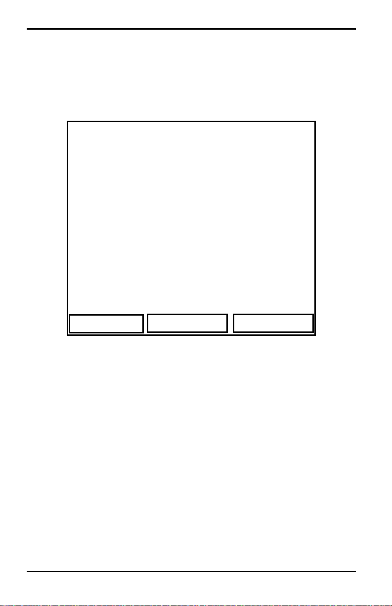
To turn the PT878 off, press the red key for 3 seconds. The screen now
appears similar to Figure 5 below.
Velocity, ft/s
SHUTDOWN: Meter OFF
Signal, dB
SLEEP: Meter Idle
CANCEL: Resume Operations
Delta-T, ns
Shutdown
Figure 5: Shutdown Menu
Three options are available:
Sleep
Volume, l/s
Resume
• Press [F1] to shut down the PT878, turning it completely off.
• Press [F2] to send the PT878 into sleep mode. In this mode, some of the
power supplies shut down, but the PT878 remains in a standby mode.
Users can resume taking measurements immediately by pressing the
power button.
• Press [F3] to cancel the command and return the PT878 to normal
operation.
If the PT878 locks up, you can reset it by holding the power key (the red key
in the upper right corner) for 15 seconds.
14 Transport® Model PT878 Portable Liquid Flowmeter User’s Manual
Loading...