


GE PSB9240DF, PSB9240SF, PSB9240BL, PSB9240EF, ZSC2200 Installation Instructions
...Installation
Instructions
Advantium®
240V Built-In SpeedCook Ovens
PSB9240DF
PSB9240SF
PSB9240BL
PSB9240EF
ZSC2200
ZSC2201
ZSC2202
49-40690-4 MFL59060926
07-20 GEA
Español
For a Spanish version of this manual, visit our Website at GEAppliances.com.
Para consultar una version en español de este manual de instrucciones, visite nuestro sitio de internet GEAppliances. com.
GE is a trademark of the General Electric Company. Manufactured under trademark license.

Safety Information
BEFORE YOU BEGIN
Read these instructions completely and carefully.
IMPORTANT — Save these
instructions for local inspector’s use.
IMPORTANT — Observe all governing codes and ordinances.
•Note to Installer — Be sure to leave these instructions with the Consumer.
•Note to Consumer — Keep these instructions with your Owner’s Manual for future reference.
•Skill Level — Installation of this appliance requires basic mechanical and electrical skills.
•Completion Time — 1 Hour.
•Proper installation is the responsibility of the installer.
•Product failure due to improper installation is not covered under the warranty. See Owner’s Manual for warranty information.
IMPORTANT — Use this oven only for its intended purpose. Never use the oven for warming or heating a room. Prolonged use of the oven without proper ventilation can be hazardous.
 CAUTION
For personal safety, remove house fuse or oven circuit breaker before beginning
installation to avoid severe or fatal shock injury.
 CAUTION
For personal safety, the mounting surface must be capable of supporting the cabinet load, in addition to the added weight of the oven and drawer, plus additional oven loads.
 CAUTION
For personal safety this product cannot be installed in cabinet arrangements such as an island, a peninsula or below a countertop.
CONTENTS |
|
Design Information |
|
Models Available ............................................... |
2 |
Product Dimensions and Clearances................ |
4 |
Tools and Parts Required ................................. |
4 |
Parts Supplied ................................................... |
4 |
Electrical Tools and Parts Required.................. |
4 |
Advance Planning ............................................. |
4 |
Installation Preparation |
|
Electrical Requirements .................................... |
5 |
Install Junction Box ........................................... |
5 |
Preparing the Opening (Installation without |
|
an accessory storage drawer)..................... |
6-7 |
Preparing the Opening (Installation with |
|
an accessory storage drawer)..................... |
8-9 |
Installation Instructions |
|
Step 1, Remove Packaging and Parts ............ |
10 |
Step 2, Route Conduit..................................... |
11 |
Step 3, Install Bottom Trim.............................. |
12 |
Step 4, Install Mounting Screws...................... |
12 |
Step 5, Finalize Installation ............................. |
12 |
MODELS AVAILABLE |
|
Models: |
|
PSB9240DFWW–White |
|
PSB9240DFBB–Black |
|
PSB9240SFSS–Stainless Steel |
|
PSB9240BLTS–Black Stainless Steel |
|
PSB9240EFES–Slate |
|
Monogram Models: |
|
ZSC2200NWW–White |
|
ZSC2200NBB–Black |
|
ZSC2201NSS–Stainless Steel |
|
ZSC2201JSS–Stainless Steel |
|
Monogram Pro Range Models:
ZSC2202NSS–Stainless Steel
ZSC2202JSS–Stainless Steel
NOTE: This unit cannot be installed with an accessory storage drawer.
2

Información de seguridad
ANTES DE COMENZAR
Lea estas instrucciones por completo y con detenimiento.
IMPORTANTE — Guarde estas instrucciones para el uso de inspectores locales.
IMPORTANTE — Cumpla con todos los códigos y ordenanzas vigentes.
• Nota al instalador — Asegúrese de dejar estas instrucciones con el Consumidor.
• Nota al consumidor — Mantenga estas instrucciones con el Manual del Propietario para referencia futura.
• Nivel de capacidad — La instalación de este aparato requiere capacidades mecánicas y eléctricas básicas.
•Tiempo de finalización — 1 hora.
•La instalación adecuada es responsabilidad del instalador.
•La garantía no cubre fallas producidas
por la instalación inadecuada del producto. Consulte el Manual del propietario para obtener información sobre la garantía.
IMPORTANTE — Utilice este horno sólo con el objetivo para el que fue creado. Nunca use el horno para entibiar o calentar una habitación. El uso prolongado del horno sin una ventilación adecuada puede resultar peligroso.

 PRECAUCIÓN
Para seguridad personal, quite el fusible o el interruptor de circuitos de la vivienda antes de comenzar la instalación a fin de evitar una lesión grave o fatal.

 PRECAUCIÓN
Para su seguridad personal, la superficie de montaje deberá poder soportar la carga del gabinete, además del peso agregado al horno y al cajón, junto con las cargas adicionales en el horno.

 PRECAUCIÓN
Para su seguridad personal, este producto no puede ser instalado en arreglos de alacena, como por ejemplo, islas, penínsulas o debajo de superficies de trabajo.
3

Design Information
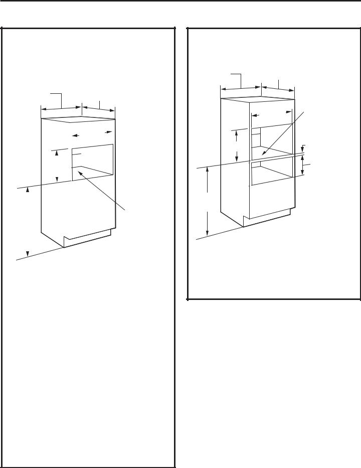
PRODUCT DIMENSIONS AND CLEARANCES NOTE: Appearance will vary by model.
21-1/2” |
29-3/4” |
1s |
|
19”
1” 
 1-3/16s

 13”
13” 
TOOLS AND PARTS REQUIRED
(NOT SUPPLIED)
•#2 Phillips screwdriver
•Hand held drill
•High speed drill bit, 3/32" diameter
•3/8" slot head screwdriver
•Level
•Saw
•2x4 or 2x2 lumber for installing runners or 3/8" plywood for floor (if required)
•Wood screws or other hardware for installing runner or shelf to support oven (if required)
•Safety glasses or goggles
PARTS SUPPLIED
•6 brass screws (3 required, 3 extra)
•5 color matched screws (4 required, 1 extra)
•Bottom trim
ELECTRICAL TOOLS AND PARTS REQUIRED (NOT SUPPLIED)
•Junction box
•Electrical cable (3-conductor or 4-conductor wire as required by local codes)
•UL-listed conduit connectors
•Wire cutters and wire strippers
4
ADVANCE PLANNING
•These ovens may be installed directly into a 30” wide oven cabinet.
•Cutout dimensions are NOT the same for installation with or without an accessory storage drawer. Make sure to use the correct cutout when preparing the opening.
NOTE: Model ZSC2202 CANNOT be installed with an accessory storage drawer. See Installation Preparation Without an Accessory Storage Drawer for this model.
IMPORTANT — This oven is not approved for use above another built-in Advantium Speedcook oven, a side by side installation or below a countertop.
•For personal safety, this oven cannot be installed in a cabinet arrangement such as an island or peninsula.
•The oven must be installed at least 36-3/4” above the floor.
•Allow for clearance to adjacent corners, walls, drawers, etc.
•Cabinets installed adjacent to wall ovens must have an adhesion spec of at least 194ºF temperature rating.
The oven must be securely installed in a cabinet that is firmly attached to the house structure. Weight on the oven door could cause the oven to tip and result in injury. Never allow anyone to climb, sit, stand or hang on the oven door.
If installing the drawer accessory, the drawer must be assembled to the oven prior to installation into the cabinet. See the Accessory Storage Drawer Assembly Instructions.

Installation Preparation
ELECTRICAL REQUIREMENTS
Single Speedcook Installation
Product rating is 120/208 or 120/240 volt, 60 Hz, 30 amps. This product must be connected to a supply circuit of the proper voltage and frequency and protected by a time delay fuse or circuit breaker. Power should be supplied from a separate, dedicated 30-ampere branch circuit. Wire size must conform to the requirements of the National Electrical Code or the prevailing local code.
Combined Speedcook and Wall Oven Installation
When installed in combination with a single wall oven, use separate electrical junction boxes.
Refer to single oven installation instructions for electrical requirements of that product.
These connections must be made by a qualified electrician. All electrical connections must meet National Electrical Code or prevailing local codes.
Combined Speedcook and Warming Drawer Installation
When installing the Speedcook oven over an electric warming drawer, a separate 120V, 60Hz, properly grounded receptacle must be installed. See instructions packed with the warming drawer.

 WARNING
•The electrical power to the oven branch circuit must be shut off while line connections are being made.
•Use copper wiring only.
•Electrical ground is required on this appliance. The free end of the green wire (ground wire) must be connected to a suitable ground.
This wire must remain grounded to the oven.
•If cold water pipe is interrupted by plastic, non-metallic gaskets, union connections or other insulating materials, DO NOT use for grounding.
•DO NOT ground to a gas pipe.
•DO NOT have a fuse in the NEUTRAL or GROUNDING circuit. A fuse in the NEUTRAL or GROUNDING circuit could result in an electrical shock.
•Check with a qualified electrician if you are in doubt as to whether the appliance is properly grounded.
Failure to follow these instructions could result in serious injury or death.
5

 ADVERTENCIA
•El encendido eléctrico al circuito paralelo deberá estar apagado mientras se realizan las conexiones de línea.
•Use conductores de cobre únicamente.
•Este electrodoméstico requiere que se realice una conexión a tierra. El extremo libre del cable verde (cable a tierra) debe estar conectado a una conexión a tierra adecuada. Este cable debe permanecer conectado a la conexión a tierra del horno.
•Si la tubería de agua fría presenta interrupciones por plásticos, juntas, conexiones de uniones u otros
materiales aislantes, NO use la misma como conexión a tierra.
•NO se debe conectar a tierra en una tubería de suministro de gas.
REQUISITOS ELÉCTRICOS (Cont)
•NO posee un fusible en el circuito neutro o de conexión a tierra. Un fusible en el circuito neutro o de conexión a tierra podría ocasionar una descarga eléctrica.
•Consulte a un electricista calificado o personal del servicio si tiene dudas de que el electrodoméstico se encuentre conectado a tierra apropiadamente.
Si no se siguen estas instrucciones, se podrán producir lesiones graves o la muerte.
INSTALL JUNCTION BOX
The conduit is located at the top right on the back of the oven.
Locate and install the junction box within reach of the oven conduit.
•Through the left or right sides of the cabinet wall and into adjacent cabinet.
•Or, through the cutout floor.
•Or, in the upper cabinet.
Cutout
Height
Installation Preparation
Preparation WITHOUT an Accessory Storage Drawer
PREPARE THE OPENING
The Advantium 240V can be installed in combination with other Built-In appliances. Always follow each product’s Installation Instructions to complete the installation.
30” 23-1/2”
|
|
|
|
|
|
|
|
|
|
|
|
|
|
|
|
|
|
|
|
|
25-1/4” |
|
|
|
|
|
|
|
|
|
|
|
|
|
||||
|
|
|
|
|
|
|
|
|
|
|
|
|
|
|
|
|
|
|
|
|
|
|
|
|
|
|
|
|
|
|
|
|
|
|
|
|
|
|
|
|
|
|
|
|
|
|
|
|
|
|
|
|
|
|
|
|
|
|
|
|
|
|
|
|
|
|
|
17-1/2” |
|
|
|
|
|
|
|
||
|
|
|
|
|
|
|
|
|
|
|||
|
|
|
|
|
|
|
|
|
|
|
|
|
|
|
|
|
|
|
|
|
|
|
|
|
Construct |
|
|
|
|
|
|
|
|
|
|
|
|
Base |
|
|
|
|
|
|
|
|
|
|
|
|
Min. 3/8” |
|
|
|
|
|
|
|
|
|
|
|
|
Plywood |
|
|
|
|
|
|
|
|
|
|
|
|
Supported |
|
|
|
|
|
|
|
|
|
|
|
by 2x4 |
|
36-3/4” |
|
|
|
|
|
|
|
|
|
|||
Min. |
|
|
|
|
|
|
|
|
|
|
or 2x2 |
|
|
|
|
|
|
|
|
|
|
|
|
|
Runners all |
|
|
|
|
|
|
|
|
|
|
|
|
|
|
|
|
|
|
|
|
|
|
||||
|
|
|
|
|
|
|
|
|
|
|
|
Four Sides |
|
|
|
|
|
|
|||||||
|
|
|
|
|
|
|
|
|
|
|
|
|
|
|
|
|
|
|
|
|
|
|
|
|
|
Single Advantium 240V Installation:
Order a 30” wide single oven cabinet or cut the opening in a wall to the dimensions shown.
•Always maintain 36-3/4” minimum height from the floor to the cutout in any single or combined installation.
•Allow the following clearances around the cutout on the front surface of the cabinet: 5/8” from the top, 2-3/8” from the side edges, and
í ´ IURP WKH ERWWRP 1RWH WKHVH UHIHU WR minimum clearances required for installation and do not reflect actual product dimensions.)
•Oven overlaps will conceal cut edges on all sides of the opening.
When installed over a single oven or a warming drawer, allow at least 2” between the two openings. This separation will provide clearance for bottom overlap of the Advantium 240V and the other appliance overlaps.
Construct a solid oven floor of 3/8” min. thick plywood supported by 2 x 4 or 2 x 2 runners on all sides.
•The support must be level and rigidly mounted, flush with the bottom edge of the cutout.
PREPARE THE OPENING (CONT.)
Installation over a Warming Drawer:
30” |
23-1/2” |
Construct |
|
|
Solid Bottom |
|
|
Min. 3/8” |
|
|
Plywood |
|
|
Supported |
|
25-1/4” |
by 2x4 or 2x2 |
|
Runners all |
|
|
|
Four Sides |
17-1/2” |
|
2” Min. |
|
(3” |
|
|
|
|
|
|
recommended) |
|
|
Per warming |
|
|
drawer |
|
|
requirement |
36-3/4” Min.
NOTE: Additional clearances between the cutouts may be required. Check to be sure the oven supports above the Warming Drawer location do not obstruct the required interior depth and height. See Warming Drawer installation instructions for details.
6

Installation Preparation
Preparation WITHOUT an Accessory Storage Drawer
PREPARE THE OPENING (CONT.)
Installation over a Wall Oven:
|
|
|
|
|
|
|
23-1/2” |
|
|
|
|
|
|
|
|
|||||
30” |
|
|
|
|
|
|
|
|
|
Construct |
||||||||||
|
|
|
|
|
|
|
|
|
|
|
|
|
|
|
|
|
|
Solid Bottom |
|
|
|
|
|
|
|
|
|
|
|
|
|
|
|
|
|
|
|
||||
|
|
|
|
|
|
|
|
|
|
|
|
|
|
|
|
|
|
Min. 3/8” |
|
|
|
|
|
|
|
|
|
|
|
|
|
|
|
|
|
|
|
|
Plywood |
|
|
|
|
|
|
|
|
|
|
|
|
|
|
|
|
|||||||
|
|
|
|
|
|
|
|
|
|
|
|
|
|
|
|
|
|
Supported by |
|
|
|
|
|
|
|
|
|
|
|
|
|
|
|
|
|
|
|
|
2x4 or 2x2 |
|
|
|
|
|
|
|
|
|
|
|
25-1/4” |
|
|
|
|
|
|
Runners all |
|
|||
|
|
|
|
|
|
|
|
|
|
|
|
|
|
|
|
|
|
Four Sides |
|
|
|
|
|
|
|
|
|
|
|
|
|
|
|
||||||||
|
|
|
|
|
|
|
|
|
|
|
|
|
|
|
|
|
|
|
||
|
|
|
|
|
|
|
|
|
|
|
|
|
|
|
|
|
|
|
||
|
|
|
|
|
|
|
|
|
|
|
|
|
|
|
|
2” Min. |
||||
|
|
|
|
|
|
|
|
|||||||||||||
|
17- |
|
1/2” |
|
|
|
|
|
|
|
|
|
||||||||
|
|
|
|
|
||||||||||||||||
|
|
|
|
|
|
|
|
|
|
|
|
|
|
|
|
|
|
(3” recommended) |
||
|
|
|
|
|
|
|
|
|
|
|
|
|
|
|||||||
|
|
|
|
|
|
|
|
|
|
|
|
|
|
|
|
|
|
|
|
|
|
|
|
|
|
|
|
|
|
|
|
|
|
|
|
|
|
|
|
|
|
|
|
|
|
|
|
|
|
|
|
|
|
|
|
|
|
|
|
|||
|
|
|
|
|
|
|
|
|
|
|
|
|
|
|
|
Per Oven |
||||
|
|
|
|
|
|
|
|
|
|
|
|
|
|
|
|
Requirement |
|
|||
45-1/4” Min.
• If you are replacing an electric double oven with the combined installation of
an Advantium 240V and a single oven, use the dimensions shown. The middle rail separating the two openings may need to be larger than the 2” minimum shown.
PREPARE THE OPENING (CONT.)
Installation over a Wall Oven and Warming Drawer:
|
|
Construct |
30” |
23-1/2” |
Solid Bottom |
|
|
Min. 3/8” |
|
|
Plywood |
|
|
Supported |
|
|
by |
|
25-1/4” |
2x4 or 2x2 |
|
Runners all |
|
|
|
Four Sides |
17-1/2” |
|
2” Min. |
|
|
|
|
|
(3” recommended) |
|
|
Per Oven |
|
|
Requirement |
45-1/4” |
|
2” Min. |
Min. |
|
|
Per warming drawer requirement |
||
NOTE: Additional clearances between the cutouts may be required. Check to be sure the oven supports above the Warming Drawer location do not obstruct the required interior depth and height. See Warming Drawer installation instructions for details.
 CAUTION For personal safety, the mounting surface must be capable of supporting the cabinet load, in addition to the added weight of the oven and drawer, plus additional oven loads.

 PRECAUCIÓN Para su seguridad personal, la superficie de montaje deberá poder soportar la carga del gabinete, además del peso agregado al horno y al cajón, junto con las cargas adicionales en el horno.
7

Installation Preparation
Preparation WITH an Accessory Storage Drawer
NOTE: MODEL ZSC2202 CANNOT BE INSTALLED WITH AN ACCESSORY STORAGE DRAWER. SEE INSTALLATION PREPARATION WITHOUT AN ACCESSORY STORAGE DRAWER FOR THIS MODEL.
PREPARE THE OPENING
The Advantium 240V can be installed in combination with other Built-In appliances. Always follow each product’s Installation Instructions to complete the installation.
Single Advantium 240V Installation:
Order a 30” wide single oven cabinet or cut the opening in a wall to the dimensions shown.
30” 23-1/2”
|
|
|
|
|
|
|
|
|
|
|
|
|
|
|
|
|
|
|
|
25-1/4” |
|
|
|
|
|
|
|
|
|
|
|
Min.* |
|
|
|
|
|
|
|
|
|
|
|
|
|
||
|
|
|
|
|
|
|
|
|
|
|
|
|
|
|
|
|
|
|
|
|
|
|
|
|
|
|
|
|
|
|
|
|
|
|
|
|
|
|
|
|
|
|
|
|
|
|
|
|
|
|
|
|
|
|
|
|
|
|
|
|
|
|
21” |
|
|
|
|
|
|
||
|
|
|
|
|
|
|
|
|
|||
|
|
|
|
|
|
|
|
|
|
|
|
|
|
|
|
|
|
|
|
|
|
|
Construct |
|
|
|
|
|
|
|
|
|
|
|
Base |
|
|
|
|
|
|
|
|
|
|
|
Min. 3/8” |
|
|
|
|
|
|
|
|
|
|
|
Plywood |
|
|
|
|
|
|
|
|
|
|
|
Supported |
|
|
|
|
|
|
|
|
|
|
by 2x4 |
|
36-3/4” |
|
|
|
|
|
|
|
|
|||
Min. |
|
|
|
|
|
|
|
|
|
or 2x2 |
|
|
|
|
|
|
|
|
|
|
|
|
Runners all |
|
|
|
|
|
|
|
|
|
|
|
|
|
|
|
|
|
|
|
|
||||
|
|
|
|
|
|
|
|
|
|
|
Four Sides |
|
|
|
|
|
|
||||||
|
|
|
|
|
|
|
|
|
|
|
|
|
|
|
|
|
|
|
|
|
|
|
|
*For existing cutouts, a maximum width of 28-1/2” is acceptable. If the opening is slightly wider, secure a furring strip on each side of the cutout for securing the oven.
•Always maintain 36-3/4” minimum height from the floor to the cutout in any single or combined installation.
•Allow the following clearances around the cutout on the front surface of the cabinet: 5/8” from the top, 2-3/8” from the side edges, and 3/4” from the bottom. (Note: these refer to minimum clearances required for installation and do not reflect actual product dimensions.)
•Oven overlaps will conceal cut edges on all sides of the opening.
PREPARE THE OPENING (CONT.)
Single Advantium 240V Installation (cont.)
When installed over a single oven or a warming drawer, allow at least 2” between the two openings. This separation will provide clearance for bottom overlap of the Advantium 240V and the other appliance overlaps.
Construct a solid oven floor of 3/8” min. thick plywood supported by 2 x 4 or 2 x 2 runners on all sides.
• The support must be level and rigidly mounted, flush with the bottom edge of the cutout.
Installation over a Warming Drawer:
30” |
23-1/2” |
Construct |
|
|
Solid Bottom |
|
|
Min. 3/8” |
|
|
Plywood |
|
25-1/4” |
Supported |
|
by 2x4 or 2x2 |
|
|
Min.* |
Runners all |
|
|
Four Sides |
|
21” |
2” Min. |
|
|
(3” recommended) |
|
|
Per warming |
|
|
drawer |
|
|
requirement |
36-3/4” Min.
*For existing cutouts, a maximum width of 28-1/2” is acceptable. If the opening is slightly wider, secure a furring strip on each side of the cutout for securing the oven.
NOTE: Additional clearances between the cutouts may be required. Check to be sure the oven supports above the Warming Drawer
location do not obstruct the required interior depth and height. See Warming Drawer installation instructions for details.
8

Installation Preparation
Preparation WITH an Accessory Storage Drawer
NOTE: MODEL ZSC2202 CANNOT BE INSTALLED WITH AN ACCESSORY STORAGE DRAWER. SEE INSTALLATION PREPARATION WITHOUT AN ACCESSORY STORAGE DRAWER FOR THIS MODEL.
PREPARE THE OPENING (CONT.)
Installation over a Wall Oven:
|
|
|
|
|
|
|
|
|
|
23-1/2” |
|
|
|
|
|
|
|
|
|||
30” |
|
|
|
|
|
|
|
|
|
|
|
|
Construct |
||||||||
|
|
|
|
|
|
|
|
|
|
|
|
|
|
|
|
|
|
|
Solid Bottom |
|
|
|
|
|
|
|
|
|
|
|
|
|
|
|
|
|
|
|
|
||||
|
|
|
|
|
|
|
|
|
|
|
|
|
|
|
|
|
|
|
Min. 3/8” |
|
|
|
|
|
|
|
|
|
|
|
|
|
|
|
|
|
|
|
|
|
Plywood |
|
|
|
|
|
|
|
|
|
|
|
|
|
|
|
|
|
|||||||
|
|
|
|
|
|
|
|
|
|
|
|
|
|
|
|
|
|
|
Supported by |
|
|
|
|
|
|
|
|
|
25-1/4” |
|
|
|
|
|
|
|
2x4 or 2x2 |
|
|||||
|
|
|
|
||||||||||||||||||
|
|
|
|
|
|
|
|
|
Min.* |
|
|
|
|
|
|
|
Runners all |
|
|||
|
|
|
|
|
|
|
|
|
|
||||||||||||
|
|
|
|
|
|
|
|
|
|
|
|
|
|
|
|||||||
|
|
|
|
|
|
|
|
|
|
|
|
|
|
|
|
|
|
|
Four Sides |
|
|
|
|
|
|
|
|
|
|
|
|
|
|
|
|
||||||||
|
|
|
|
|
|
|
|
|
|
|
|
|
|
|
|
|
|
|
|
|
|
|
|
|
|
|
|
|
|
|
|
|
|
|
|
|
|
|
|
|
|
|
|
|
|
|
|
|
|
|
|
|
|
|
|
|
|
|
|
|
|
|
|
|
|
|
|
|
|
|
|
|
|
|
|
|
|
|
|
|
|
|
|
|
|||
|
|
|
21” |
|
|
|
|
|
|
|
|
|
|
|
2” Min. |
||||||
|
|
|
|
||||||||||||||||||
|
|
|
|
|
|
|
|
|
|
|
|
|
|
|
|
|
|
|
(3” recommended) |
||
|
|
|
|
|
|
|
|
|
|
|
|
|
|
|
|
|
|
|
|
|
|
|
|
|
|
|
|
|
|
|
|
|
|
|
|
|
|
|
|
|
|
|
|
|
|
|
|
|
|
|
|
|
|
|
|
|
|
|
|
|
|
|
|||
|
|
|
|
|
|
|
|
|
|
|
|
|
|
|
|
|
Per Oven |
||||
|
|
|
|
|
|
|
|
|
|
|
|
|
|
|
|
|
Requirement |
|
|||
45-1/4” Min.
*For existing cutouts, a maximum width of 28-1/2” is acceptable. If the opening is slightly wider, secure a furring strip on each side of the cutout for securing the oven.
• If you are replacing an electric double oven with the combined installation of
an Advantium 240V and a single oven, use the dimensions shown. The middle rail separating the two openings may need to be larger than the 2” minimum shown.
PREPARE THE OPENING (CONT.)
Installation over a Wall Oven and |
|||||||||||||
Warming Drawer: |
|
|
|
|
|
|
|
|
|
||||
|
|
|
|
|
|
|
|
Construct |
|||||
|
|
|
|
|
|
|
|
|
|
Solid Bottom |
|||
|
30” |
|
|
|
|
||||||||
|
|
|
|
23-1/2” |
|
|
|
|
|||||
|
|
|
|
|
|
|
|
|
|
|
|
|
Min. 3/8” |
|
|
|
|
|
|
|
|
|
|
|
|
|
Plywood |
|
|
|
|
|
|
|
|
|
|
|
|
|
Supported |
|
|
|
|
|
|
|
|
|
|
|
|||
|
|
|
|
|
|
|
|
|
|
|
|
|
by |
|
|
|
|
|
25-1/4” |
|
|
|
|
|
2x4 or 2x2 |
||
|
|
|
|
|
|
||||||||
|
|
|
|
|
Min.* |
|
|
|
|
|
Runners all |
||
|
|
|
|
|
|
|
|
|
|
|
|
|
Four Sides |
|
|
|
|
|
|
|
|
|
|
||||
|
|
|
|
|
|
|
|
|
|
|
|
|
|
21” |
2” Min. |
(3” recommended)
Per Oven
Requirement
45-1/4” |
2” Min. |
|
|
Min. |
Per warming drawer requirement |
|
*For existing cutouts, a maximum width of 28-1/2” is acceptable. If the opening is slightly wider, secure a furring strip on each side of the cutout for securing the oven.
NOTE: Additional clearances between the cutouts may be required. Check to be sure the oven supports above the Warming Drawer location do not obstruct the required interior depth and height. See Warming Drawer installation instructions for details.
 CAUTION For personal safety, the mounting surface must be capable of supporting the cabinet load, in addition to the added weight of the oven and drawer, plus additional oven loads.

 PRECAUCIÓN Para su seguridad personal, la superficie de montaje deberá poder soportar la carga del gabinete, además del peso agregado al horno y al cajón, junto con las cargas adicionales en el horno.
9
Installation Instructions
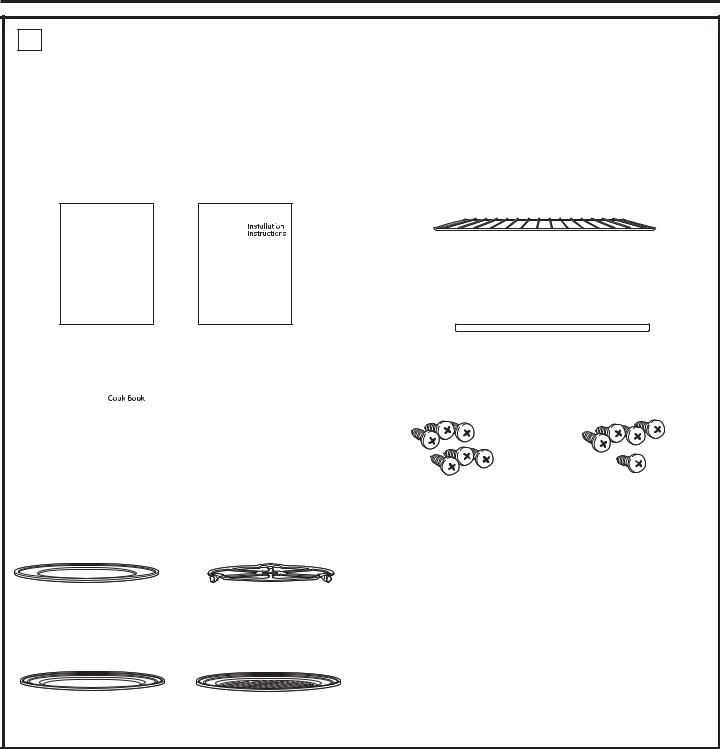
1 REMOVE THE PACKAGING AND PARTS
•Remove all packing material and tape.
•Locate parts package containing mounting
screws.
•Remove the oven from the carton. Do not lift unit by handle or conduit. Two people are required to lift this oven.
•Open the door and remove any packaging in oven.
Owner’s
Manual
|
|
|
|
|
Installation |
|
Owner’s Manual |
||||
|
|
|
|
|
Instructions |
|
|
|
|||
|
|
|
|
|
|
|
|
|
|
|
|
|
|
|
|
|
Cooking |
|
|
|
|
|
Guide |
|
|
|
|
|
|
|
|
|
|
|
|
|
|
|
|
|
|
|
Cook Book |
|
|
|
|
|
|
|
|
|
Cooking Guide |
||
|
|
|
|
|
|
|
|
|
|
|
|
|
|
|
|
|
|
|
|
|
Glass Tray |
Turntable Ring |
Rack
Bottom Trim
|
|
|
|
|
|
|
|
|
|
|
|||
|
6 Brass Screws |
|
5 Color Matched Screws |
|||
(3 required, 3 extra) |
|
(4 required, 1 extra) |
||||
|
|
|
|
|
|
|
|
|
|
|
|
|
|
IMPORTANT: If installing the Advantium 240V Oven with an accessory storage drawer, read the storage drawer assembly instructions to assemble the products together before proceeding to Step 2.
|
|
|
|
|
|
|
|
|
|
|
|
|
|
|
|
|
|
|
|
|
|
|
|
|
|
|
|
|
Metal Grill Tray |
|||||
|
Metal Trays (2) |
|
|
|||
|
|
|
|
|
|
|
10
 Loading...