


PVM2070DM1BB
GE PVM2070DM1BB, PVM2070DM1CC, PVM2070DM1WW, PVM2070DM2BB, PVM2070DM2CC Installation Guide
...
Installation
Instructions
Overthe Range
Microwave Oven
PVM2070
Questions?Call800.GE.CARES(800.432.2737)or Visit,,,, x_ebsite;,t:ge.com
BEFORE YOU BEGIN
Read these instructions completely and carefully.
• IMPORTANT - S_,,e_hese
instructions for local inspector's use.
• IMPORTANT - Obse,,e;,ll
goxernin(, codes and ordinances.
• Note to Installer - Be sure to leaxe these
instructions with the (_onsumer.
o
o
o
o
Note to Consumer - Keep these
instructions for futm'e reterence.
Skill level - Installation of this appliance requires
basic mechanical and electrical skills.
Proper installation is the responsibility of the installer.
Product thilm'e due to iml)roper installation is not
coxered trader the _'arrantx.
Fora Spanish version of thismanual,visitour Websiteat ge.com.
Para consultaruna versionen espa_ol de estemanual de instrucciones,visitenuestrositio
de internetge.com.
READ CAREFULLY.
KEEP THESE INSTRUCTIONS.
Installation Instructions
CONTENTS
General information
hnportant Safety Instructions .................................. 3
Electrical Requirements .......................................... 3
Hood Exhaust ...................................................... 4, 5
Damage - Shipment/InstaJlation .............................. 6
Parts Included. ......................................................... 6
Tools You Will Need ................................................ 7
Mounting Space ...................................................... 7
Step-by-step installation guide
Placement of Mounting Plate ............................ 8-10
Removing tire Mounting Plate ...................... 8
Finding the _4all Studs ................................. 8
Determining _.lll Plate l.oration .................. 9
Aliguiug the Wall Plate ............................... 10
Installation Types .................................. 11-22
_] ()utside Top ............................
Exhaust
12-14
Attach Mounting Plate to W;fll ....... 12
Preparation of Top Cabinet .......... 13
Checking 1or Proper Damper
Operation ............................................ 13
Mount the Microwave Oven .......... 13
A_!just tire Exhaust Adaptor .......... 14
Connerting Durtwork .......................... 14
_ Outside Back Exhaust 15-18
Preparing Rear _'\';dl ti)r
Outside Bark Exhaust .......................... 15
Remove Exhaust Adaptor .................... 15
Attach Mounting Plate to _4"01 ....... 16
Preparation of Top CaNnel .......... 16
Adapting Microwave Blower
for Outside Back Exhaust ................ 16, 17
Mount the Microwave Oven .......... 18
Redrculating ........................................ 19-22
Attach Mounting Plate to _4all .......... 19
Preparation of Top Cabinet .............. 19
Cherk Microwave Assembly .......... 20
Adapting Microwave Blower
tot Red_'ulation ......................... 20, 21
Mount the Microwave Oveu .......... 21, 22
Installing the Charcoal Filter ...... ........ 22
Before You Use Your Microwave .......................... 23
2
Installation Instructions
iMPORTANT SAFETY iNSTRUCTiONS
This product requires a three-prong groronled outlet.
The installer must perflmu a ground continuit_ check
on the power outlet box befl_re beginning the
installation to insm'e that the outlet box is properly
grotmded. If not properly grotmded, or if the outlet
box does not meet electrical requirements noted
(troder E1,E(_TRICAI_ REQLIIREMENTS), a qualified
electrician should be employed to correct any
deficiencies.
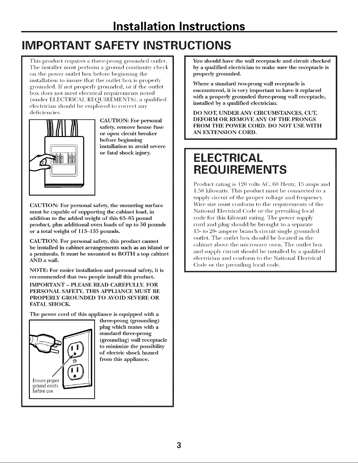
CAUTION: For persona]
safety, remove house fuse
or open circuit breaker
before beg_g
iusmllation to avoid severe
or fatal shock injury.
CAUTION: For personal safety, the mounting surface
must be capable of supporting the cabinet load, in
addition to the added weight of this 63-85 pound
product, plus additional oven loads of up to 50 pounds
or a total weight of 113-135 pounds.
CAUTION: For personal safety, this product cannot
be installed in cabinet arrangements such as an island or
a peninsula. It must be mounted to BOTH a top cabinet
AND a wall.
NOTE: For easier installation and personal safety, it is
recommended that two people install this product.
IMPORTANT - PLEASE READ CAREFULLY. FOR
PERSONAL SAFETY, THIS APPLIANCE MUST BE
PROPERLY GROUNDED TO AVOID SEVERE OR
FATAL SHOCK,
The power cord of this appliance is equipped with a
tKree-prong (grounding)
plug which mates with a
standard three-prong
(grounding) wall receptacle
to minimize the possibility
of electric shock hazard
from tiffs appliance.
Ensureproper
groundexists
beforeuse
You should have the wall receptacle and circuit checked
by a qualified electrician to mane sure the receptacle is
properly grounded.
Where a standard two-prong wall receptacle is
encountered, it is very important to have it replaced
with a properly grounded three-prong wall receptacle,
installed by a qualified electriciaJa.
DO NOT, UNDER ANY CIRCUMSTANCES, CUT,
DI_'ORM OR REMOVE ANY OF THE PRONGS
FROM THE POWER CORD. DO NOT USE WITH
AN EXTENSION CORD.
ELECTRICAL
REQUIREMENTS
Product rating is 120 volts AC, 60 Hertz, 15 amps and
1.58 kilowatts. This product must be connected to a
supply circuit of the proper voltage and ti'equency,
Wire size must conflwm to the requirements of the
National Electrical Code or the pre\zdling local
code ti_r this kilowatt rating. The power supply
cord and plug shoMd be brought to a separate
15- to 20- ampere branch circuit single grounded
outlet, The outlet box should be located in the
cabinet above the microwave oven. The outlet box
and supply circuit should be installed by a qualified
electrician and con%tin to the National Electrical
Code or the pre\_dling local code.
3
Installation Instructions
HOOD EXHAUST
NOTE: Read these next two pages tufty if you plan to vent your exhaust to the
outside. If you plan to recirculate the air back into the room, proceed to page 6.
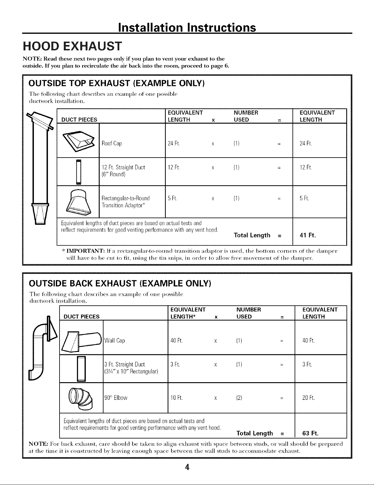
OUTSIDE TOP EXHAUST (EXAMPLE ONLY)
The following chart describes an example ot one possible
ductwork installation.
DUCT PIECES
EQUIVALENT NUMBER
LENGTH x USED
RoofCap 24 Ft. x
12Ft.StraightDuct 12Ft. x
(6" Round)
-_ Rectangular-to-Round 5Ft. x
TransitionAdaptor*
Equivalentlengthsof duct piecesare basedonactualtests and
reflectrequirementsfor goodventingperformancewith anyventhood.
(1)
(1)
(1)
Total Length
EQUIVALENT
LENGTH
24 Ft.
12Ft.
5Ft.
41 Ft.
* IMPORTANT: If a rectangulat_to-round transition adaptor is used, the bottom cornets of the damper
will haxe to be cut to fit, usin,,._ the tin snips, in order to allow free moxement of the damper.
OUTSIDE BACK EXHAUST (EXAMPLE ONLY)
The following chart describes an example ot one possible
ductwork installation.
[
DUC_ PIECES
_Wall Cap
(_ 90° Elbow
EQUIVALENT NUMBER
LENGTH* x USED
40Ft. x (1)
3 Ft. x (1)3 Ft.StraightDuct
3W' x 10" Rectangular)
10Ft. x (2)
EQUIVALENT
LENGTH
40Ft.
3 Ft.
20Ft.
Equivalent lengths of duct piecesare based on actual tests and
reflect requirements for good venting performance with any vent hood.
Total Length = 63 Ft.
NOTE: For back exhaust, care should be taken to align exhaust with space between studs, or wall should be prepared
at the time it is const_ ucted by leaving enough space between the wall studs to accommodate exhaust.
4
Installation Instructions
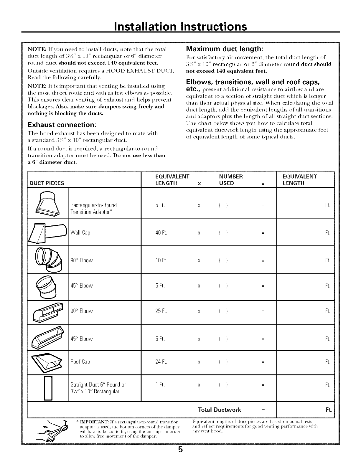
NOTE: If wm need to install ducts, note that the total
duct lengti_ of 3¼" x ] O" rectangular or 6" diameter
round duct should not exceed 140 equivalent feet.
Outside ventilation requires a HOOD EXHAUST DUCT.
Read the following careflfllv.
NOTE: It is important that venting be installed using
the most direct route and with as few elbows as possible.
This ensm'es clear venting of exhaust and helps prevent
blockages. Also, make sure dmnpers swing freely and
nothing is blocking the ducts.
Exhaust connection:
The hood exhaust has been designed to mate with
a standard 3Vt" x 10" rectangular duct.
If a round duct is required, a rectangula_to-rotmd
transition adaptor inust be used. Do not use less than
a 6" diameter duct.
Maximum duct length:
For satisfiwtorv air movement, the total duct length of
3¼" x ] 0" rectangular or 6" diameter round duct should
not exceed 140 equivalent feet,
Elbows, transitions, wall and roof caps,
etc., present additional resistance to airflow and are
equiwdent to a section of straight duct which is longer
than their actual physical size. When calculating the total
duct length, add the equiwdent lengths of all transitions
and adaptors plus the length of all straight duct sections.
The chart below shows w)u how to calculate total
equivalent ductwork length using the approximate feet
of equiwdent length of some typical ducts.
EQUIVALENT NUMBER EQUIVALENT
DUCT PIECES LENGTH x USED = LENGTH
Rectangular-to-Round 5Ft. x ( ) = Ft.
TransitionAdaptor*
..,,..,,.-%
Wall Cap 40 Ft. x ( ) = Ft.
()_ 90° Elbow 10Ft. x ( ) = Ft.
45° Elbow 5Ft. x ( ) = Ft.
90° Elbow 25Ft. x ( ) = Ft.
J 45° Elbow 5Ft. x ( ) = Ft.
RoofCap 24Ft. x ( ) = Ft.
StraightDuct6" Roundor 1Ft. x ( ) = Ft.
3W' x 10" Rectangular
Total Ductwork = Ft.
* IMPORTANT: If a r_( tangulal_to-round transilion Equival< nl 1_ngths o[ du_t pie_<s are bas<d on aclual lests
adaptor is used, the bottom comers of th( dampel and ret]ect requiremenls tk)r good venling performanc( with
xdll hax< to b< Clll to fit, using Ih(t lill snips, in ordel any vent hood.
to allm_ free lllOVelllelll of Ihe (]alllpel.
5
Installation Instructions
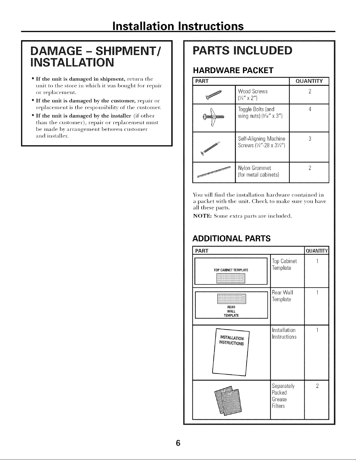
DAMAGE - SHIPMENT/
iNSTALLATiON
* If the unit is damaged in shipment, return the
unit to the store in which it was bought fin" repair
or replacement,
® If the unit is damaged by the customer, repair or
replacement is the responsibility of the customer.
® If the unit is damaged By the installer (if other
th;m the customer), repair or replacement must
be made by ;uT;mgement between customer
and installer.
PARTS iNCLUDED
HARDWARE PACKET
PART QUANTITY
Wood Screws 2
(Y4"x2")
ToggleBolts(and 4
wing nuts)(_" x 3")
Self-AligningMachine 3
Screws(W'-28x 31/4")
NylonGrommet 2
(for metal cabinets)
You will find the installation hardware contained in
a packet with the unit, Check to inake sure you have
all these parts.
NOTE: Some extI'a parts are inchlded.
ADDITIONAL PARTS
PART
TOPCABINETTEMPLATE
REAR
WALL
TEMPLATE
LATION
INSTRUCTIONS
TopCabinet
Template
RearWall
Template
Installation
Instructions
Separately
Packed
Grease
Filters
QUANTITY
1
6
Installation Instructions
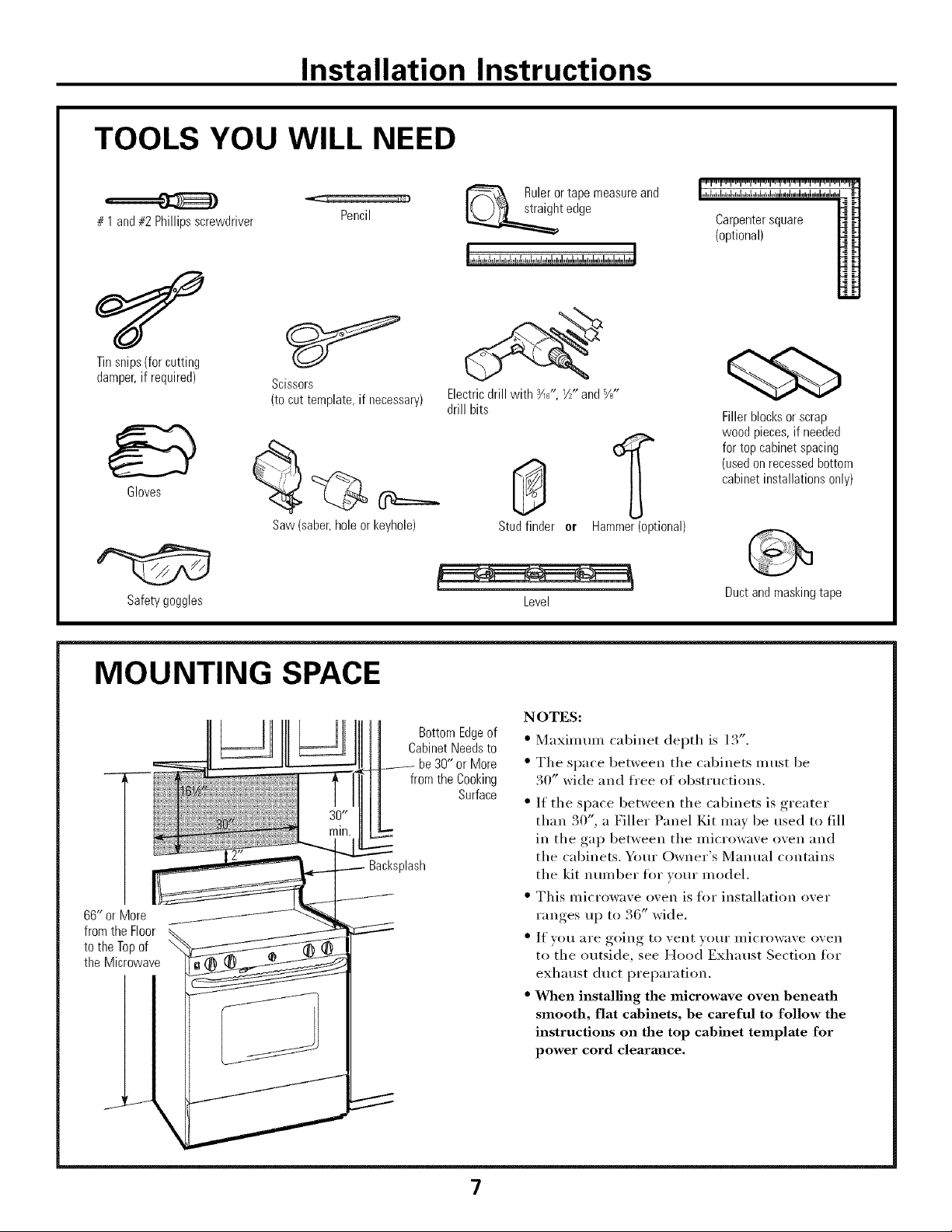
TOOLS YOU WILL NEED
# 1 and#2Phillipsscrewdriver
Pencil
Tinsnips(forcutting
damper,if required)
Scissors
(to cut template, if necessary)
Gloves
Safety goggles
Saw (saber, hole or keyhole)
Rulerortapemeasureand
t edge
Electric drill with ¾_", V/" and %"
drill bits
Stud finder or Hammer (optional)
Level
Carpenter square
(optional)
Fillerblocksor scrap
woodpieces,if needed
fortopcabinetspacing
(usedonrecessedbottom
cabinetinstallationsonly)
Duct and masking tape
MOUNTING SPACE
66" or More
fromthe Floor
tothe Topof
the Microwave
\
BottomEdgeof
CabinetNeedsto
be30" or More
from the Cooking
Surface
Backsplash
NOTES:
• Maxinmm cabinet depth is 13".
• The space between the cabinets illtlst be
30" wide and fl'ee of obstructions.
• If the space between the cabinets is greater
than 30", a Filler Panel Kit may be used to fill
in the gap between the microwave oven and
the cabinets, Your Owner's Manual contains
the kit number fin" wmr model.
• This microwave oven is fl_r installation over
ranges up to 36" wide.
• If you are going to vent your microwave oven
to the outside, see Hood Exhaust Section tin"
exhaust duct preparation.
• When installing the microwave oven Beneath
smooth, flat cabinets, he careful to follow the
instructions on the top cabinet template for
power cord clearmlce.
7
Installation Instructions
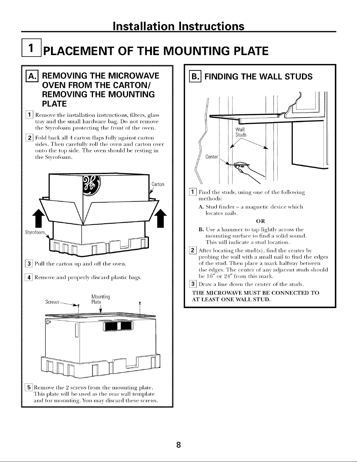
I- PLACEMENT OF THE MOUNTING PLATE
N REMOVING THE MICROWAVE
OVEN FROM THE CARTON/
REMOVING THE MOUNTING
PLATE
_ Remove the installation instructions, filters, glass
tray and the small hardware bag. Do not remove
the Swrofl)am protecting the fl'ont of the oven.
[] Fold back all 4 carton flaps flflly against carton
sides. Then careflfllv roll the oven and carton over
onto the top side. m'he oven should be resting in
the Stvrofl)am.
_Pull the carton up and off the oven.
[] Remove and properly discard plastic bags.
Mounting
Plate
!
i
[]Remove the 2 screws from the mounting plate.
This plate will be used as the rear wall template
and for mounting. You max discard these screws.
N FINDING THE WALL STUDS
_ Center
_Find the studs, usino one of the followiw,
methods:
A. Stud finder - a magnetic device which
locates nails.
OR
B. Ilse a hammer to tap lightly across the
mounting surihce to find a solid s(mnd.
This will indicate a stud location.
_ After the stud find tile bylocating
(s), centel"
probing the wall with a small nail to find the edges
of the stud. Then place a mark haltway between
the edges. Tile center of any ac!jacent studs should
be 16" or 24" fl'om this mark.
_Draw a line down the center of tile sttlds.
THE MICROWAVE MUST BE CONNECTED TO
AT LE&ST ONE WALL STUD.
8
Installation Instructions
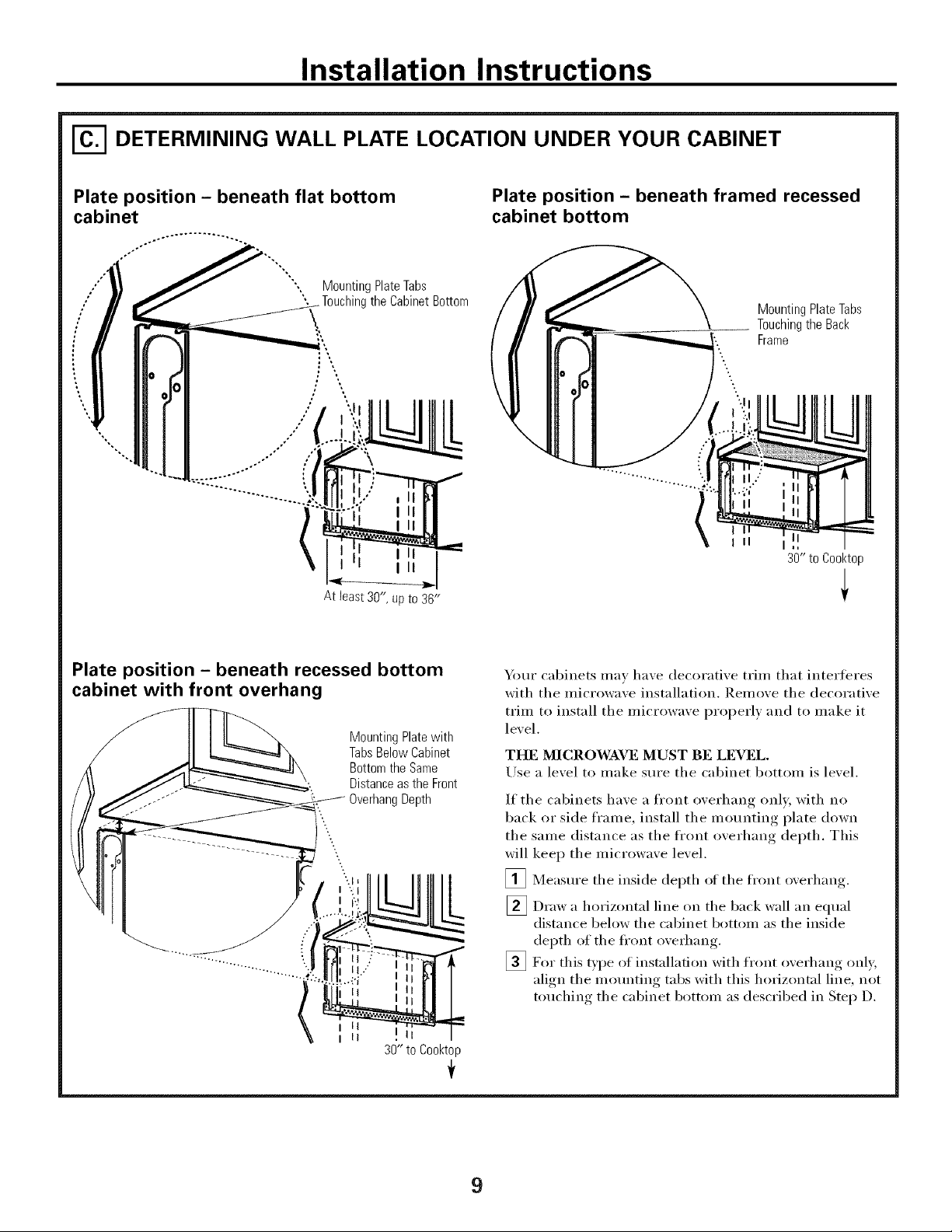
DETERMINING WALL PLATE LOCATION UNDER YOUR CABINET
Plate position - beneath flat bottom
%*,
Mounting Plate Tabs
'', the Cabinet Bottom
/ ill
III
III
At least30",upto 36"
Plate position - beneath framed recessed
cabinet bottom
Mounting Plate Tabs
Touching the Back
Frame
III I
30" to Cooktop
Plate position - beneath recessed bottom
cabinet with front overhang
Mounting Plate with
Tabs Below Cabinet
Bottom the Same
Distance as the Front
g Depth
\
\
L
I II
I II
30" to Cooktop
Your cabinets may have decorative trim that interieres
with the microwave installation. Remove the decorative
trim to install the microwave i)roperly and to make it
level.
THE MICROWAVE MUST BE LEVEL.
Use a level to make sure the cabinet bottom is level.
If the cabinets have a fl'ont overhang only, with no
back or side fl'ame, install the mounting plate down
the same distance as the fl'ont overhang depth. This
will keep the microwave level.
_ Measm'e the inside depth oI the fl'ont overhang.
[] Draw a horizontal line on the back wall an equal
distance below the cabinet bottom as the inside
depth of the front overhang.
_For this type of instnllation with fl'ont overhang only,
align the motmting tabs with this horizontnl line, not
touching the cabinet bottom as described in Step D.
9
Installation Instructions
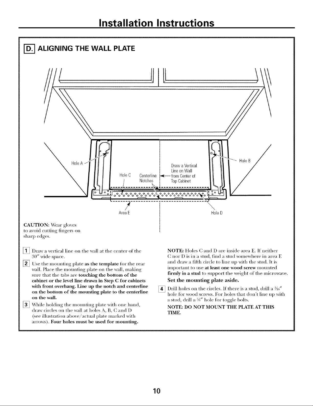
ALIGNING THE WALL PLATE
CAUTION: _,_ar glo_es
to a_oid cutting finge_ on
sharp edces
O "
,
o-,:)OoOo OoOoyoOoOoOo °o°o°oOo
AreaE H01eD
¢
/
-'-'- HoleB J
/
[]Draw a vertical line on the wall at the center of the
30" wide space.
_Use the moui_ting plate as the template for the rear
wall. Place the motmting plate on the wall, making
sure that the tabs are touchhag the bottom of the
cabinet or the level line drawn in Step C for cabinets
with front overhm_g. Line up the notch and centerline
on the bottom of the mounting plate to the centerlhle
on the wall.
_ \._]file holding the mounting plate with one hand,
draw drcles on the wall at holes A, B, C and D
(see illustratioi_ above/actual plate marked with
arrows). Four holes must be used for mounting.
[]
NOTE: Holes C and D are inside area E. If neither
C nor D is in a stud, find a stud somewhere in area E
"and draw "afilth circle to line up with the stud. It is
important to use at least one wood screw mortared
f'trmly in a stud to support the weight of the microwave.
Set the mounting plate aside.
Drill holes on the circles. If there is a stud, drill a :_A_,"
hole fi:,r wood scre_:s. For holes that don't line up with
a stud, chill a %" hole fin" toggle bolts.
NOTE: DO NOT MOUNT THE PLATE AT THIS
TIME.
10
Installation Instructions
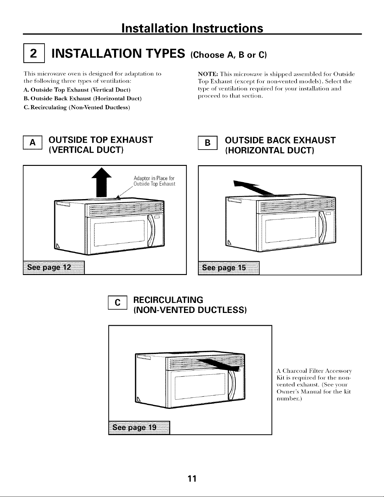
I2-] INSTALLATION TYPES
This microwave oven is designed for adaptation to
the tolh)wing three types of ventilation:
A. Outside Top Exhaust (Vertical Duct)
B. Outside Back Exhaust (Horizontal Duct)
C. Recirculating (Non-Vented Ductless)
(Choose A, B or C)
NOTE: This microwave is shii)ped assembled fl_r Outside
Top Exhaust (except ti)r non-vented models). Select the
type of ventilation required for vom" installation and
proceed to that section.
_-_ OUTSIDE TOP EXHAUST
(VERTICAL DUCT)
OUTSIDE BACK EXHAUST
(HORIZONTAL DUCT)
1
Adaptorin Placefor
OutsideTopExhaust
[-_ RECIRCULATING
(NON-VENTED DUCTLESS)
A Charcoal Filter Accessory
Kit is required fl_r the non-
vented exhaust. (See your
Owner's Manual for the kit
number.)
11
Installation Instructions
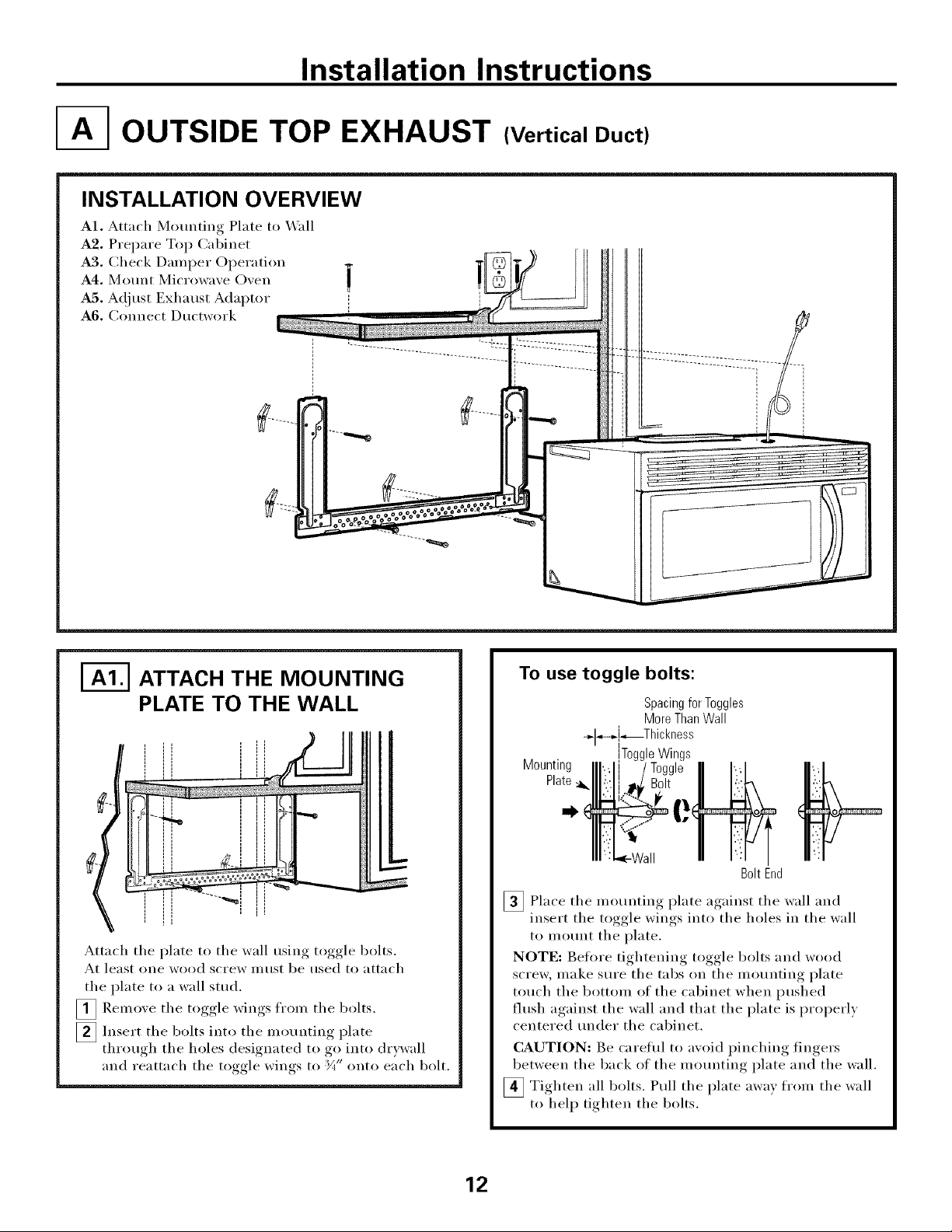
OUTSIDE TOP EXHAUST (Vertical Duct)
INSTALLATION OVERVIEW
A1. Attach Mom_ting Plate to _\'all
A2. Prepare Top Cabinet
A3. Check Damper Operation
A4, Mom_t Microwave Oven
A5. A(!just Exhaust Adaptor ',
A6. Connect Ductwork "
I-_ ATTACH THE MOUNTING
PLATE TO THE WALL
Attach tile plate to tile wall using toggle bolts.
At least one wood screw nlust be used to attach
the plate to a wall stud.
[]Remove the toggle wings fl'om the bolts.
[]Insert tile bolts into tile mounting plate
through the holes designated to go into drywall
and reattach the toggle wings to '_A"onto each bolt.
To use toggle bolts:
Mounting
Plate :_
Spacingfor Toggles
MoreThanWall
÷l_,.i-_Th ckness
ToggleWings
BoltEnd
[]Place tile mounting plate against tile wall and
insert tile toggle wings into tile holes in tile wall
to mount tile plate.
NOTE: Betore tightening toggle bolts and wood
scre_, make sure tile tabs on tile mounting plate
touch tile bottom of tile cabinet when pushed
flush against the wall and that the plate is properly
centered under the cabinet.
CAUTION: Be careflfl to axoid Ilinchin'*_ fingers
between the back of the motmting plate and the wall.
_ Tighten all bolts. Pull the plate awax from the wall
to help tighten the bolts.
12
Installation Instructions
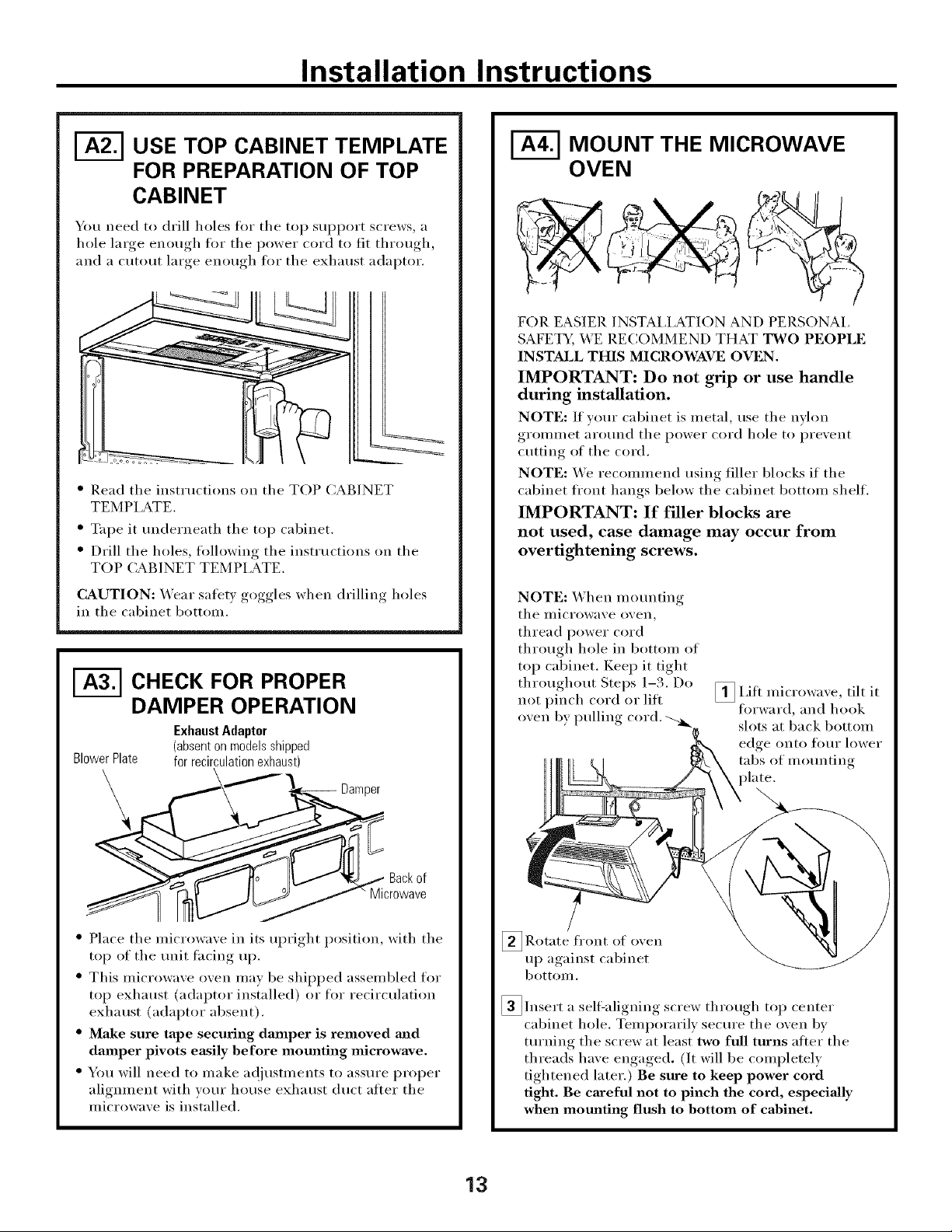
I-_ USE TOP CABINET TEMPLATE
FOR PREPARATION OF TOP
CABINET
You need to drill holes fl)r the top SUl)port screws, a
hole large enough for the power cord to fit throu ,h
and a cutout large enough for the exhaust adaptor.
%
" Read the instructions on tile TOP CABINET
TEMPLATE.
" Tape it tmderneath the top cabinet.
" Drill the holes, following the insnuctions on the
TOP CABINET TEMPLATE.
CAUTION: Wear safety goggles when drilling holes
in the cabinet bottom.
I-_ CHECK FOR PROPER
DAMPER OPERATION
BlowerPlate
Exhaust Adaptor
(absenton modelsshipped
for recirculationexhaust)
Damper
Backof
Microwave
" Place tile microwave in its uI)right position, with tile
top of tile unit tacing up.
" This microwave oven mav be shil)ped assembled for
top exhaust (adaptor installed) or fl)r recirculation
exhaust (adaptor absent).
" Make sure tape securing damper is removed and
damper pivots easily before mom_ting microwave.
" You will need to make ac!jUStlnents to assure proper
alignment with yore" house exhaust duct atter the
microwave is installed.
MOUNT THE MICROWAVE
OVEN
FOIl EASIER INSTAI,IATION AND PERSONAI,
SAFETY, WE RECOMMEND THAT TWO PEOPLE
INSTALL THIS MICROWAVE OVEN.
IMPORTANT: Do not grip or use handle
during installation.
NOTE: If your cabinet is metal, use tile nylon
grolnu/et _li'O/lnd tile power cord hole to l)revent
cutting of tile cord.
NOTE: We recommend using filler blocks if tile
cabinet fl'ont hangs below tile cabinet bottom shelf.
IMPORTANT: If filler blocks are
not used, case damage may occur from
overtightening screws.
NOTE: When motmting
tile ulici'owave ovell_
thread power cord
through hole in bottom of
top cabinet. Kee I) it tight
throughout Steps 1-3. Do
not pinch cord or lift
oven by pulling cord.
_I,ifl tilt it
inicrowave,
forward, and hook
slots at back bottom
edge onto [()/lI" lower
tabs of mounting
_Rotate fI'Ollt of
o_en
up against cabinet
bottoI//.
_lnsert a sell=aligning screw through top center
cabinet hole. Temporarily secure the oven by
turning the screw at least two full turns atter the
threads have engaged. (It will be completely
tightened later.) Be sure to keep power cord
tight. Be careful not to pinch the cord, especially
when mounting flush to bottom of cabinet.
13
Installation Instructions
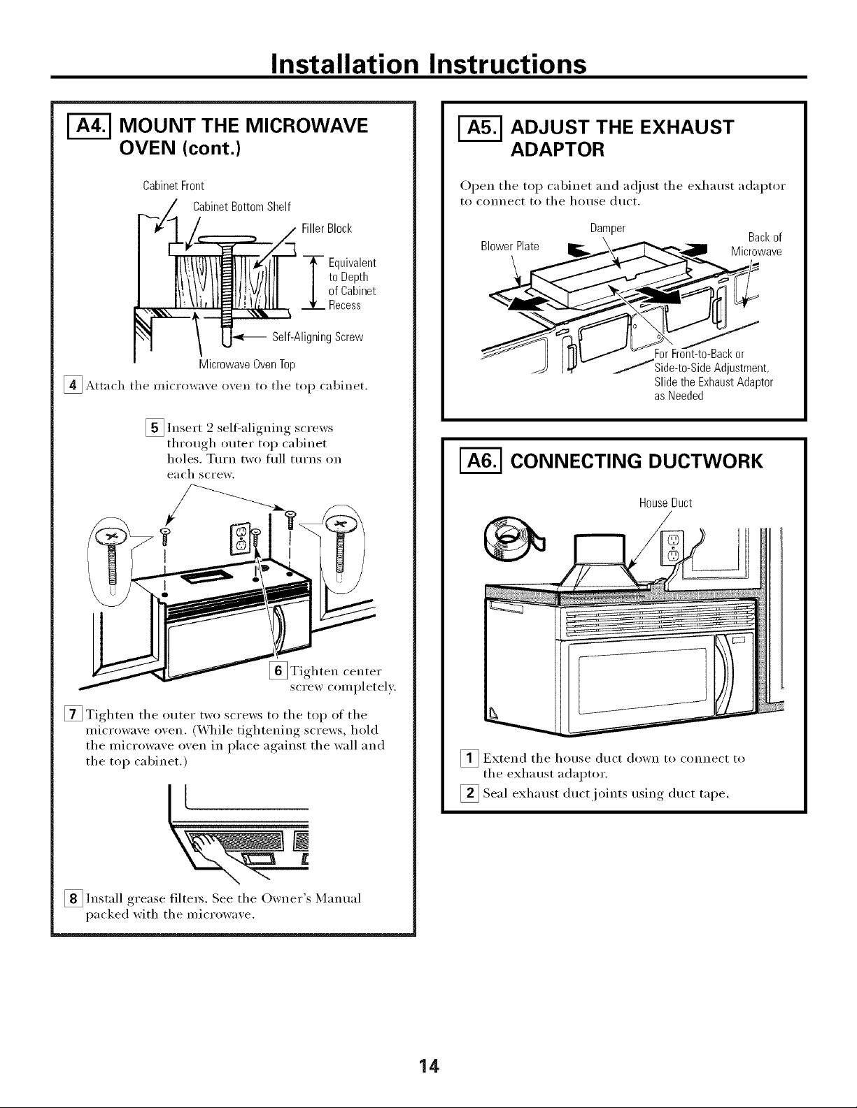
I-_ MOUNT THE MICROWAVE
OVEN (cont.)
CabinetFront
CabinetBottomShelf
FillerBlock
_ quivalent
toDepth
ofCabinet
Recess
Self-AligningScrew
MicrowaveOvenTop
[]Attach tile microwave oven to tile top cabinet.
[] Insert 2 selfZaligning screws
through outer top cabinet
holes. TtlI'IX tWO fllll ttlI'ns on
each screw.
[]Tighten center
screw completely.
[] Tighten tile outer two screws to tile top of tile
microwave oven. (While tightening screws, hold
tile microwave oven in place against tile wall and
tile top cabinet.)
II
S /
[]Install filte_s. See tile Owner Manualgrease
packed with tile microwave.
ADJUST THE EXHAUST
ADAPTOR
Open tile top cabinet and a(!iust tile exhaust adaptor
to connect to tile house duct.
Damper
, Backof
BlowerPlate _ --\__ Microwave
[ I III / _ ForFront-to-Backor
" _ I_l/_ /Side-to-Side Adjustment,
Slidethe ExhaustAdaptor
asNeeded
I-_ CONNECTING DUCTWORK
HouseDuct
_ Extend tile hot/se duct down to connect to
tile exhaust adaptor.
] , . , , , duct tape.
Seal exhaust duct ioints using
14
Installation Instructions
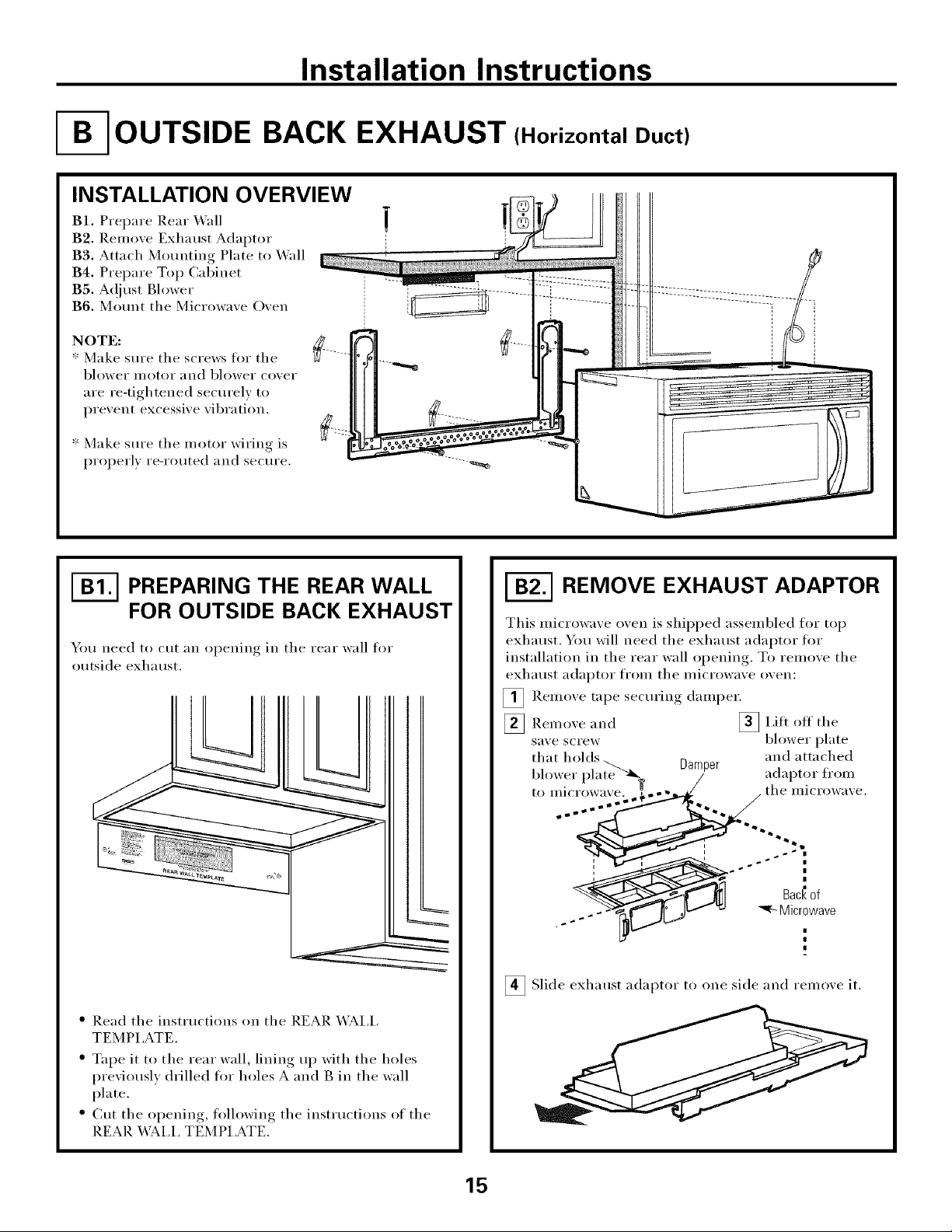
OUTSIDE BACK EXHAUST (Horizontal Duct)
INSTALLATION OVERVIEW
B1. Prel)are Rear Wall
B2. Renlove Exhaust Adaptor
B3. Attach Mounting Plate to _'all
B4. Prel)are Top Cabinet
BS. A_!just Blower
B6. Mount tile Microwave Oven
NOTE:
* Make sure tile screws fin" tile
blower ii/otoi" and blower cover
are re-tightened securely to
l)revent excessive vibration.
* Make sure tile niotor wiring is
l)rol)erl } re-routed and secure.
I-_ PREPARING THE REAR WALL
FOR OUTSIDE BACK EXHAUST
Yo/I need to tilt }111 l
O )eniIl_* in tile rear wall for
outside exhaust.
" Read tile instiuctions on tile REAR X4__I,i,
TEMPI ,ATE.
" Tape it to tile rear wall, lining up with tile holes
previously drilled fin" holes A and B in the wall
plate.
" Cut the oi)ening, tollowing the instiuctions of the
REAR X__I,I, TEMPI,ATE.
REMOVE EXHAUST ADAPTOR
This niicrowave oven is shii)ped assen/bled for top
exhaust. You will need tile exhaust adaptor tor
installation in tile rear wall oi)ening. To renlove tile
exhaust a(laptoi" t1"()I11 tile i/iicFowave ()veil:
[] Renlove tape securing dainl)er.
_Rein oxe and [] I,ift off the
sa;e screw blower plate
that Damper and attached
blower adaptor fronl
to IlliCI'OWaVe,
n
1
Bac_of
_'_ Microwave
I
_ Slide exhaust adaptor to one side and reinoxe it.
15
 Loading...