


 Loading...
Digital Energy
Multilin
MultiLink ML1200
Managed Field Switch
Instruction Manual
Firmware Revision 3.3x
Manual P/N: 1601-9095-A1
Manual Order Code: GEK-113538
Copyright © 2009 GE Multilin
GE Multilin
215 Anderson Avenue, Markham, Ontario
Canada L6E 1B3
Tel: (905) 294-6222 Fax: (905) 201-2098 Internet: http://www.GEmultilin.com
*1601-9095-A1*
|
|
|
T |
E |
|
|
|
|
|
IS |
R |
||||
|
G |
|
|
||||
R |
E |
|
|
|
|
E |
|
|
|
|
|
|
D |
||
|
|
|
|
|
|
|
|
ISO9001:2000 |
|||||||
E |
|
|
|
|
|
IN |
|
G |
|
|
|
|
L |
||
|
|
|
|
I |
|
||
|
|
MULT |
|
|
|||
|
|
|
|
|
|
|
|
GE Multilin's Quality Management System is registered to ISO9001:2000
QMI # 005094
UL # A3775
These instructions do not purport to cover all details or variations in equipment nor provide for every possible contingency to be met in connection with installation, operation, or maintenance. Should further information be desired or should particular problems arise which are not covered sufficiently for the purchaser’s purpose, the matter should be referred to the General Electric Company.
To the extent required the products described herein meet applicable ANSI, IEEE, and NEMA standards; but no such assurance is given with respect to local codes and ordinances because they vary greatly.
© 2009 GE Multilin Incorporated. All rights reserved.
GE Multilin Multilink ML1200 instruction manual for revision 3.3x.
Multilink ML1200 is a registered trademark of GE Multilin Inc.
NEBS is a trademark of Telcordia Technologies
The contents of this manual are the property of GE Multilin Inc. This documentation is furnished on license and may not be reproduced in whole or in part without the permission of GE Multilin. The content of this manual is for informational use only and is subject to change without notice.
Part numbers contained in this manual are subject to change without notice, and should therefore be verified by GE Multilin before ordering.
Part number: 1601-9095-A1 (June 2009)
Federal Communications Commission Radio Frequency Interference Statement
This equipment generates, uses and can radiate frequency energy and if not installed and used properly in strict accordance with the manufacturer's instructions, may cause interference to radio communication. It has been tested and found to comply with the limits for a Class A computing device in accordance with the specifications in Subpart J of Part 15 of FCC rules, which are designed to provide reasonable protection against such interference when operated in a commercial environment. Operation of this equipment in a residential area is likely to cause interference, in which case the user, at their own expense, will be required to take whatever measures may be required to correct the interference.
Canadian Emissions Statement
This Class A digital apparatus meets all requirements of the Canadian Interference-Causing Equipment Regulations.
Electrical Safety requirements:
1.This product is to be installed Only in Restricted Access Areas (Dedicated Equipment Rooms, Electrical Closets, or the like).
2.48 V DC products shall be installed with a readily accessible disconnect device in the building installation supply circuit to the product.
3.This product shall be provided with a maximum 10 A DC Listed fuse or circuit breaker in the supply circuit when connected to a 48 V centralized DC source.
4.The external power supply for DC units shall be a Listed, Direct Plug In power unit, marked Class 2, or Listed ITE Power Supply, marked LP, which has suitably rated output voltage (i.e. 24 V DC or 48 V DC) and suitable rated output current.
5.Product does not contain user replaceable fuses. Any internal fuses can ONLY be replaced by GE Multilin.

TOC |
TABLE OF CONTENTS |
Table of Contents
1: INTRODUCTION |
GETTING STARTED ............................................................................................................................. |
1-1 |
|
INSPECTING THE PACKAGE AND PRODUCT ........................................................................ |
1-1 |
|
ORDER CODES ..................................................................................................................................... |
1-2 |
|
SPECIFICATIONS ................................................................................................................................. |
1-3 |
|
COMMAND LINE INTERFACE FIRMWARE ................................................................................. |
1-7 |
|
CONSOLE CONNECTION ....................................................................................................... |
1-7 |
|
CONSOLE SETUP .................................................................................................................... |
1-7 |
|
CONSOLE SCREEN ................................................................................................................. |
1-8 |
|
LOGGING IN FOR THE FIRST TIME ....................................................................................... |
1-8 |
|
AUTOMATIC IP ADDRESS CONFIGURATION ....................................................................... |
1-8 |
|
SETTING THE IP PARAMETERS USING CONSOLE PORT .................................................... |
1-9 |
|
PRIVILEGE LEVELS .................................................................................................................. |
1-11 |
|
USER MANAGEMENT ............................................................................................................. |
1-12 |
|
HELP ........................................................................................................................................ |
1-13 |
|
EXITING ................................................................................................................................... |
1-14 |
|
ENERVISTA SECURE WEB MANAGEMENT ............................................................................... |
1-15 |
|
LOGGING IN FOR THE FIRST TIME ....................................................................................... |
1-15 |
|
PRIVILEGE LEVELS .................................................................................................................. |
1-17 |
|
USER MANAGEMENT ............................................................................................................. |
1-17 |
|
MODIFYING THE PRIVILEGE LEVEL ...................................................................................... |
1-21 |
|
HELP ........................................................................................................................................ |
1-22 |
|
EXITING ................................................................................................................................... |
1-22 |
|
ML1200 FIRMWARE UPDATES ..................................................................................................... |
1-24 |
|
UPDATING MULTILINK ML1200 FIRMWARE .................................................................... |
1-24 |
|
SELECTING THE PROPER VERSION ...................................................................................... |
1-24 |
|
UPDATING THROUGH THE COMMAND LINE ....................................................................... |
1-24 |
|
UPDATING THROUGH THE ENERVISTA SECURE WEB MANAGEMENT SOFTWARE ........ |
1-26 |
|
|
|
2: PRODUCT DESCRIPTION |
OVERVIEW ............................................................................................................................................. |
2-1 |
|
FOUR-PORT SFF FIBER MODULES (CC MODULE, CD MODULE), 100MB FIBER ......... |
2-3 |
|
FOUR-PORT COPPER MODULE, C1 MODULE MDIX) ................................................... |
2-4 |
|
POE (POWER PASS-THROUGH), C2 MODULE (MDIX), 10/100MB 4-PORT ............... |
2-4 |
|
TWO-PORT FIBER MODULES, 2@ 100MB FIBER ........................................................... |
2-5 |
|
TWO -PORT 10 MB MM FIBER ST MODULES ................................................................... |
2-5 |
|
SFP GIGABIT (1000MBPS) PORT MODULES ..................................................................... |
2-6 |
|
PACKET PRIORITIZATION, 802.1P QOS ............................................................................. |
2-6 |
|
FRAME BUFFERING AND FLOW CONTROL ......................................................................... |
2-7 |
|
MANAGED NETWORK FIRMWARE FOR MULTILINK ML1200-SERIES ........................... |
2-7 |
|
FEATURES AND BENEFITS .............................................................................................................. |
2-8 |
|
APPLICATIONS ..................................................................................................................................... |
2-10 |
|
|
|
3: INSTALLATION |
PREPARATION ...................................................................................................................................... |
3-1 |
|
LOCATING MULTILINK ML1200 SWITCHES ...................................................................... |
3-1 |
|
CONNECTING ETHERNET MEDIA ................................................................................................. |
3-2 |
|
MECHANICAL INSTALLATION ....................................................................................................... |
3-6 |
|
DIN-RAIL MOUNTING THE MULTILINK ML1200 ............................................................ |
3-6 |
|
ELECTRICAL INSTALLATION ........................................................................................................... |
3-8 |
|
POWERING THE MULTILINK ML1200 MANAGED FIELD SWITCH ................................ |
3-8 |
MULTILINK ML1200 MANAGED FIELD SWITCH – INSTRUCTION MANUAL |
TOC–I |

TABLE OF CONTENTS
|
ALARM CONTACTS FOR MONITORING INTERNAL POWER, AND SOFTWARE TRAPS |
.....3-8 |
|
ML1200 PORT MODULE (PM) INSTALLATION ................................................................. |
3-9 |
|
CONNECTING A MANAGEMENT CONSOLE TERMINAL |
|
|
TO MULTILINK ML1200 (SERIAL-RJ-45 CONSOLE PORT) ........ |
3-10 |
|
|
|
4: OPERATION |
FUNCTIONALITY .................................................................................................................................. |
4-1 |
|
SWITCHING FUNCTIONALITY ................................................................................................ |
4-1 |
|
STATUS LEDS ........................................................................................................................ |
4-2 |
|
AUTO-CROSS (MDIX) AND AUTO-NEGOTIATION, FOR RJ-45 PORTS ........................... |
4-2 |
|
FLOW-CONTROL, IEEE 802.3X STANDARD ...................................................................... |
4-3 |
|
POWER BUDGET CALCULATIONS FOR ML1200 PM’S WITH FIBER MEDIA ................. |
4-4 |
|
MULTILINK ML1200 MANAGED FIELD SWITCH PORT MODULES ................................. |
4-6 |
|
INSPECTING THE PACKAGE AND PRODUCT ........................................................................ |
4-6 |
|
ML1200 MODULES ............................................................................................................. |
4-6 |
|
BEFORE CALLING FOR ASSISTANCE .................................................................................... |
4-13 |
|
|
|
5: IP ADDRESSING |
IP ADDRESS AND SYSTEM INFORMATION ............................................................................... |
5-1 |
|
OVERVIEW .............................................................................................................................. |
5-1 |
|
IMPORTANCE OF AN IP ADDRESS ............................................................................................... |
5-3 |
|
DHCP AND BOOTP ............................................................................................................... |
5-3 |
|
BOOTP DATABASE .................................................................................................................. |
5-3 |
|
CONFIGURING DHCP/BOOTP/MANUAL/AUTO .............................................................. |
5-3 |
|
USING TELNET ....................................................................................................................... |
5-5 |
|
SETTING PARAMETERS .................................................................................................................... |
5-8 |
|
SETTING SERIAL PORT PARAMETERS .................................................................................. |
5-8 |
|
SYSTEM PARAMETERS ........................................................................................................... |
5-8 |
|
DATE AND TIME ..................................................................................................................... |
5-9 |
|
NETWORK TIME ..................................................................................................................... |
5-10 |
|
SYSTEM CONFIGURATION .............................................................................................................. |
5-14 |
|
SAVING AND LOADING – COMMAND LINE ........................................................................ |
5-14 |
|
CONFIG FILE ........................................................................................................................... |
5-14 |
|
DISPLAYING CONFIGURATION .............................................................................................. |
5-17 |
|
SAVING CONFIGURATION ..................................................................................................... |
5-20 |
|
SCRIPT FILE ............................................................................................................................ |
5-22 |
|
SAVING AND LOADING – ENERVISTA SOFTWARE ............................................................. |
5-23 |
|
HOST NAMES ......................................................................................................................... |
5-25 |
|
ERASING CONFIGURATION ................................................................................................... |
5-27 |
|
IPV6 .......................................................................................................................................................... |
5-31 |
|
INTRODUCTION TO IPV6 ....................................................................................................... |
5-31 |
|
WHAT’S CHANGED IN IPV6? ............................................................................................... |
5-31 |
|
IPV6 ADDRESSING ................................................................................................................ |
5-32 |
|
CONFIGURING IPV6 .............................................................................................................. |
5-33 |
|
LIST OF COMMANDS IN THIS CHAPTER ................................................................................ |
5-34 |
|
|
|
6: ACCESS |
SECURING ACCESS ............................................................................................................................ |
6-1 |
CONSIDERATIONS |
DESCRIPTION .......................................................................................................................... |
6-1 |
|
PASSWORDS ........................................................................................................................... |
6-1 |
|
PORT SECURITY FEATURE ..................................................................................................... |
6-2 |
|
CONFIGURING PORT SECURITY THROUGH THE COMMAND LINE INTERFACE ....... |
6-3 |
|
COMMANDS ............................................................................................................................ |
6-3 |
|
ALLOWING MAC ADDRESSES ............................................................................................. |
6-4 |
TOC–II |
MULTILINK ML1200 MANAGED FIELD SWITCH – INSTRUCTION MANUAL |

TOC |
TABLE OF CONTENTS |
|
|
SECURITY LOGS ..................................................................................................................... |
6-8 |
|
AUTHORIZED MANAGERS ..................................................................................................... |
6-10 |
|
CONFIGURING PORT SECURITY WITH ENERVISTA SOFTWARE ..................................... |
6-12 |
|
COMMANDS ............................................................................................................................ |
6-12 |
|
LOGS ....................................................................................................................................... |
6-15 |
|
AUTHORIZED MANAGERS ..................................................................................................... |
6-16 |
|
|
|
7: ACCESS USING RADIUS |
INTRODUCTION TO 802.1X ............................................................................................................ |
7-1 |
|
DESCRIPTION .......................................................................................................................... |
7-1 |
|
802.1X PROTOCOL ............................................................................................................... |
7-1 |
|
CONFIGURING 802.1X THROUGH THE COMMAND LINE INTERFACE ......................... |
7-4 |
|
COMMANDS ............................................................................................................................ |
7-4 |
|
EXAMPLE ................................................................................................................................. |
7-6 |
|
CONFIGURING 802.1X WITH ENERVISTA SECURE |
|
|
WEB MANAGEMENT SOFTWARE ............................................................ |
7-9 |
|
COMMANDS ............................................................................................................................ |
7-9 |
|
|
|
8: ACCESS USING |
INTRODUCTION TO TACACS+ ....................................................................................................... |
8-1 |
TACACS+ |
OVERVIEW .............................................................................................................................. |
8-1 |
|
TACACS+ FLOW .................................................................................................................. |
8-2 |
|
TACACS+ PACKET ............................................................................................................... |
8-2 |
|
CONFIGURING TACACS+ THROUGH THE COMMAND LINE INTERFACE .................... |
8-4 |
|
COMMANDS ............................................................................................................................ |
8-4 |
|
EXAMPLE ................................................................................................................................. |
8-4 |
|
CONFIGURING TACACS+ WITH ENERVISTA SECURE |
|
|
WEB MANAGEMENT SOFTWARE ............................................................ |
8-6 |
|
|
|
9: PORT MIRRORING AND |
PORT MIRRORING .............................................................................................................................. |
9-1 |
SETUP |
DESCRIPTION .......................................................................................................................... |
9-1 |
|
PORT MIRRORING USING THE COMMAND LINE INTERFACE .......................................... |
9-2 |
|
COMMANDS ............................................................................................................................ |
9-2 |
|
PORT SETUP ......................................................................................................................................... |
9-3 |
|
COMMANDS ............................................................................................................................ |
9-3 |
|
FLOW CONTROL .................................................................................................................... |
9-5 |
|
BACK PRESSURE .................................................................................................................... |
9-5 |
|
BROADCAST STORMS ............................................................................................................ |
9-7 |
|
LINK LOSS ALERT .................................................................................................................. |
9-9 |
|
PORT MIRRORING USING ENERVISTA SECURE |
|
|
WEB MANAGEMENT SOFTWARE ............................................................ |
9-11 |
|
COMMANDS ............................................................................................................................ |
9-11 |
|
PORT SETUP ........................................................................................................................... |
9-12 |
|
BROADCAST STORMS ............................................................................................................ |
9-15 |
|
|
|
10: VLAN |
VLAN DESCRIPTION .......................................................................................................................... |
10-1 |
|
OVERVIEW .............................................................................................................................. |
10-1 |
|
TAG VLAN VS. PORT VLAN ............................................................................................... |
10-3 |
|
CONFIGURING PORT VLANS THROUGH THE COMMAND LINE INTERFACE ............. |
10-5 |
|
DESCRIPTION .......................................................................................................................... |
10-5 |
|
COMMANDS ............................................................................................................................ |
10-5 |
|
CONFIGURING PORT VLANS WITH ENERVISTA SECURE |
|
MULTILINK ML1200 MANAGED FIELD SWITCH – INSTRUCTION MANUAL |
TOC–III |

TABLE OF CONTENTS
|
WEB MANAGEMENT SOFTWARE ............................................................ |
10-7 |
|
DESCRIPTION .......................................................................................................................... |
10-7 |
|
CONFIGURING TAG VLANS THROUGH THE COMMAND LINE INTERFACE ................ |
10-12 |
|
DESCRIPTION .......................................................................................................................... |
10-12 |
|
COMMANDS ............................................................................................................................ |
10-12 |
|
EXAMPLE ................................................................................................................................. |
10-13 |
|
CONFIGURING TAG VLANS WITH ENERVISTA SECURE |
|
|
WEB MANAGEMENT SOFTWARE ............................................................ |
10-19 |
|
DESCRIPTION .......................................................................................................................... |
10-19 |
|
|
|
11: VLAN REGISTRATION |
OVERVIEW ............................................................................................................................................. |
11-1 |
OVER GARP |
DESCRIPTION .......................................................................................................................... |
11-1 |
|
GVRP CONCEPTS .................................................................................................................. |
11-1 |
|
GVRP OPERATIONS .............................................................................................................. |
11-2 |
|
CONFIGURING GVRP THROUGH THE COMMAND LINE INTERFACE ............................ |
11-7 |
|
COMMANDS ............................................................................................................................ |
11-7 |
|
GVRP OPERATION NOTES ................................................................................................... |
11-7 |
|
CONFIGURING GVRP WITH ENERVISTA SECURE |
|
|
WEB MANAGEMENT SOFTWARE ............................................................ |
11-9 |
|
EXAMPLE ................................................................................................................................. |
11-9 |
|
|
|
12: SPANNING TREE |
OVERVIEW ............................................................................................................................................. |
12-1 |
PROTOCOL (STP) |
DESCRIPTION .......................................................................................................................... |
12-1 |
|
FEATURES AND OPERATION ................................................................................................. |
12-1 |
|
CONFIGURING STP ............................................................................................................................ |
12-3 |
|
|
|
13: RAPID SPANNING |
OVERVIEW ............................................................................................................................................. |
13-1 |
TREE PROTOCOL |
DESCRIPTION .......................................................................................................................... |
13-1 |
|
RSTP CONCEPTS ................................................................................................................... |
13-1 |
|
TRANSITION FROM STP TO RSTP ....................................................................................... |
13-2 |
|
CONFIGURING RSTP THROUGH THE COMMAND LINE INTERFACE ............................. |
13-4 |
|
NORMAL RSTP ...................................................................................................................... |
13-4 |
|
SMART RSTP (RING-ONLY MODE) THROUGH |
|
|
THE COMMAND LINE INTERFACE (CLI) ........................................... |
13-13 |
|
CONFIGURING STP/RSTP WITH ENERVISTA SECURE |
|
|
WEB MANAGEMENT SOFTWARE ............................................................ |
13-15 |
|
NORMAL RSTP ...................................................................................................................... |
13-15 |
|
SMART RSTP (RING-ONLY MODE) WITH ENERVISTA SECURE |
|
|
WEB MANAGEMENT SOFTWARE ..................................................... |
13-19 |
|
|
|
14: QUALITY OF SERVICE |
QOS OVERVIEW .................................................................................................................................. |
14-1 |
|
DESCRIPTION .......................................................................................................................... |
14-1 |
|
QOS CONCEPTS ..................................................................................................................... |
14-1 |
|
DIFFSERV AND QOS ............................................................................................................. |
14-2 |
|
IP PRECEDENCE ..................................................................................................................... |
14-2 |
|
CONFIGURING QOS THROUGH THE COMMAND LINE INTERFACE .............................. |
14-4 |
|
COMMANDS ............................................................................................................................ |
14-4 |
|
EXAMPLE ................................................................................................................................. |
14-6 |
|
CONFIGURING QOS WITH ENERVISTA SECURE |
|
|
WEB MANAGEMENT SOFTWARE ............................................................ |
14-9 |
TOC–IV |
MULTILINK ML1200 MANAGED FIELD SWITCH – INSTRUCTION MANUAL |

TOC |
TABLE OF CONTENTS |
|
|
DESCRIPTION .......................................................................................................................... |
14-9 |
|
|
|
15: IGMP |
OVERVIEW ............................................................................................................................................. |
15-1 |
|
DESCRIPTION .......................................................................................................................... |
15-1 |
|
IGMP CONCEPTS .................................................................................................................. |
15-1 |
|
IP MULTICAST FILTERS ......................................................................................................... |
15-4 |
|
RESERVED ADDRESSES EXCLUDED FROM IP MULTICAST (IGMP) FILTERING ............... |
15-5 |
|
IGMP SUPPORT ..................................................................................................................... |
15-5 |
|
CONFIGURING IGMP THROUGH THE COMMAND LINE INTERFACE ............................. |
15-6 |
|
COMMANDS ............................................................................................................................ |
15-6 |
|
EXAMPLE ................................................................................................................................. |
15-8 |
|
CONFIGURING IGMP WITH ENERVISTA SECURE |
|
|
WEB MANAGEMENT SOFTWARE ............................................................ |
15-11 |
|
EXAMPLE ................................................................................................................................. |
15-11 |
|
|
|
16: SNMP |
OVERVIEW ............................................................................................................................................. |
16-1 |
|
DESCRIPTION .......................................................................................................................... |
16-1 |
|
SNMP CONCEPTS ................................................................................................................. |
16-1 |
|
TRAPS ...................................................................................................................................... |
16-3 |
|
STANDARDS ............................................................................................................................ |
16-3 |
|
CONFIGURING SNMP THROUGH THE COMMAND LINE INTERFACE ........................... |
16-5 |
|
COMMANDS ............................................................................................................................ |
16-5 |
|
EXAMPLE ................................................................................................................................. |
16-6 |
|
CONFIGURING SNMP WITH ENERVISTA SECURE |
|
|
WEB MANAGEMENT SOFTWARE ............................................................ |
16-11 |
|
EXAMPLE ................................................................................................................................. |
16-11 |
|
CONFIGURING RMON ...................................................................................................................... |
16-15 |
|
DESCRIPTION .......................................................................................................................... |
16-15 |
|
COMMANDS ............................................................................................................................ |
16-15 |
|
|
|
17: MISCELLANEOUS |
E-MAIL ..................................................................................................................................................... |
17-1 |
COMMANDS |
DESCRIPTION .......................................................................................................................... |
17-1 |
|
COMMANDS ............................................................................................................................ |
17-2 |
|
EXAMPLE ................................................................................................................................. |
17-3 |
|
STATISTICS ............................................................................................................................................ |
17-5 |
|
VIEWING PORT STATISTICS WITH ENERVISTA SECURE |
|
|
WEB MANAGEMENT SOFTWARE ..................................................... |
17-5 |
|
SERIAL CONNECTIVITY ..................................................................................................................... |
17-7 |
|
DESCRIPTION .......................................................................................................................... |
17-7 |
|
HISTORY ................................................................................................................................................. |
17-8 |
|
COMMANDS ............................................................................................................................ |
17-8 |
|
PING ......................................................................................................................................................... |
17-9 |
|
PING THROUGH THE COMMAND LINE INTERFACE ............................................................ |
17-9 |
|
PING THROUGH ENERVISTA SECURE WEB MANAGEMENT SOFTWARE ......................... |
17-9 |
|
PROMPT .................................................................................................................................................. |
17-10 |
|
CHANGING THE COMMAND LINE PROMPT ........................................................................ |
17-10 |
|
SYSTEM EVENTS ................................................................................................................................. |
17-11 |
|
DESCRIPTION .......................................................................................................................... |
17-11 |
|
COMMAND LINE INTERFACE EXAMPLE ............................................................................... |
17-11 |
|
ENERVISTA EXAMPLE ............................................................................................................ |
17-12 |
|
COMMAND REFERENCE .................................................................................................................. |
17-14 |
MULTILINK ML1200 MANAGED FIELD SWITCH – INSTRUCTION MANUAL |
TOC–V |

TABLE OF CONTENTS
|
MAIN COMMANDS ................................................................................................................. |
17-14 |
|
CONFIGURATION COMMANDS .............................................................................................. |
17-16 |
|
|
|
18: MODBUS PROTOCOL |
MODBUS CONFIGURATION ........................................................................................................... |
18-1 |
|
OVERVIEW .............................................................................................................................. |
18-1 |
|
COMMAND LINE INTERFACE SETTINGS ............................................................................... |
18-1 |
|
ENERVISTA SETTINGS ............................................................................................................ |
18-3 |
|
MEMORY MAPPING ........................................................................................................................... |
18-4 |
|
MODBUS MEMORY MAP ....................................................................................................... |
18-4 |
|
FORMAT CODES ..................................................................................................................... |
18-37 |
|
|
|
APPENDIX A |
REVISION HISTORY ............................................................................................................................ |
A-1 |
|
CHANGE NOTES ..................................................................................................................... |
A-1 |
|
CHANGES TO THE MANUAL .................................................................................................. |
A-1 |
|
WARRANTY ........................................................................................................................................... |
A-2 |
|
GE MULTILIN WARRANTY STATEMENT .............................................................................. |
A-2 |
|
|
|
APPENDIX B: DC POWER |
SPECIFICATIONS FOR MULTILINK ML1200 SWITCHES, DC POWER |
|
INPUT |
AT 24 V AND –48 V AND 125 V DC POWER INPUT ......................... |
B-2 |
|
-48 V DC, 24 V DC AND 125 V DC POWER, THEORY OF OPERATION ......................... |
B-3 |
|
APPLICATIONS FOR DC POWERED ETHERNET SWITCHES ............................................... |
B-4 |
|
ML1200, -48 V, 24 V, 125 V DC INSTALLATION ..................................................................... |
B-5 |
|
UL REQUIREMENTS FOR DC-POWERED UNITS ..................................................................... |
B-6 |
|
OPERATION ........................................................................................................................................... |
B-7 |
APPENDIX C: INTERNAL DC DUAL-SOURCE POWER INPUT OPTION
SPECIFICATIONS FOR MULTILINK ML1200 FIELD SWITCH .............................................. |
C-2 |
MULTILINK ML1200 WITH -48 V DC, 24 V DC |
|
AND 125 V DC DUAL-SOURCE OPTION ............................................... |
C-3 |
DUAL-SOURCE OPTION THEORY OF OPERATION ................................................................ |
C-4 |
FEATURES AND BENEFITS OF THE DUAL-SOURCE DESIGN ............................................ |
C-5 |
INSTALLATION ..................................................................................................................................... |
C-6 |
TOC–VI |
MULTILINK ML1200 MANAGED FIELD SWITCH – INSTRUCTION MANUAL |

Digital Energy
Multilin
Multilink ML1200
Managed Field Switch
Chapter 1: Introduction
1.1Getting Started
1.1.1 Inspecting the Package and Product
Examine the shipping container for obvious damage prior to installing this product; notify the carrier of any damage that you believe occurred during shipment or delivery. Inspect the contents of this package for any signs of damage and ensure that the items listed below are included.
This package should contain:
•Multilink ML1200 Managed Field Switch, base unit (configured with user-selected port module options installed)
•1 Set of two metal vertical mounting brackets, with screws to the case
•1 Installation and User Guide (this manual)
•1 Product Registration Card
Remove the items from the shipping container. Be sure to keep the shipping container should you need to re-ship the unit at a later date. To validate the product warranty, please complete and return the enclosed Product Registration Card to GE Multilin as soon as possible.
In the event there are items missing or damaged, contact the party from whom you purchased the product. If the unit needs to be returned, please use the original shipping container if possible. Refer to Section 6, Troubleshooting, for specific return procedures.
MULTILINK ML1200 MANAGED FIELD SWITCH – INSTRUCTION MANUAL |
1–1 |

INTRODUCTION |
CHAPTER 1: INTRODUCTION |
1.2Order Codes
ML1200 |
- * |
- * |
- * |
- * |
- * |
- * |
|
* |
ML1200 |
|
|
|
|
|
|
|
|
Module |
|
Slot A |
Slot B |
Slot C |
Slot D |
|
|
|
ML1200 |
| |
| |
| |
| |
| |
| |
Base Unit |
|
Power Supply |
250S |
| |
| |
| |
| |
| |
ML1200 250VDC Chassis |
|
|
125S |
| |
| |
| |
| |
| |
ML1200 125VDC Chassis |
|
|
48VS |
| |
| |
| |
| |
| |
ML1200 48VDC Chassis |
|
|
24VS |
| |
| |
| |
| |
| |
ML1200 24VDC Chassis |
|
|
12VS |
| |
| |
| |
| |
| |
ML1200 12VDC Chassis |
|
|
125D |
| |
| |
| |
| |
| |
ML1200 125VDC Chassis - Dual Input PSU |
|
|
48VD |
| |
| |
| |
| |
| |
ML1200 48VDC Chassis - Dual Input PSU |
|
|
24VD |
| |
| |
| |
| |
| |
ML1200 24VDC Chassis - Dual Input PSU |
|
|
48PS |
| |
| |
| |
| |
| |
ML1200 48VDC Chassis - PoE enabled |
|
|
48PD |
| |
| |
| |
| |
| |
ML1200 48VDC Chassis - PoE enabled with Dual Input PSU |
|
Modules |
|
| |
XX |
XX |
XX |
| |
None |
|
|
|
C1 |
| |
| |
| |
| |
4 x 10/100 RJ-45 |
|
|
|
| |
C1 |
C1 |
| |
| |
4 x 10/100 RJ-45 |
|
Only with ML1200-48 models |
|
C2 |
C2 |
| |
| |
| |
4 x 10/100 RJ-45 PoE-enabled ports (only with ML1200-48P models) |
|
|
|
|
C3 |
C3 |
| |
| |
2 x10/100 RJ-45 + 2x 100Mbit MTRJ mm Fiber |
|
|
|
|
C4 |
C4 |
| |
| |
2x |
10/100 RJ-45 + 2x 100Mbit LC mm Fiber |
|
|
|
C5 |
C5 |
| |
| |
2x |
10/100 RJ-45 + 2x 100Mbit LC sm Fiber 15km |
|
|
|
C6 |
C6 |
| |
| |
2x |
10/100 RJ-45 + 1x 100Mbit SC mm Fiber |
|
|
|
C7 |
C7 |
| |
| |
2x |
10Mbit ST mm Fiber |
|
|
|
C8 |
C8 |
C8 |
| |
2x |
100Mbit ST mm Fiber |
|
|
|
C9 |
C9 |
C9 |
| |
2x |
100Mbit SC mm Fiber |
|
|
|
CA |
CA |
CA |
| |
2x |
100Mbit SC sm Fiber 20km |
|
|
|
CB |
CB |
CB |
| |
2x |
100Mbit SC sm Fiber 40km |
|
|
|
CC |
CC |
CC |
| |
4x |
100Mbit MTRJ mm Fiber |
|
|
|
CD |
CD |
CD |
| |
4x |
100Mbit LC mm Fiber |
|
|
|
CE |
CE |
CE |
| |
4x |
100Mbit LC sm Fiber 15km |
|
|
|
|
| |
CF |
| |
1x |
100Mbit ST mm Fiber |
|
|
|
|
| |
CG |
| |
1x |
100Mbit SC mm Fiber |
|
|
|
|
| |
CH |
| |
1x |
100Mbit SC sm Fiber 20km |
|
|
|
|
| |
CI |
| |
1x |
100Mbit SC sm Fiber 40km |
|
|
|
|
| |
CJ |
| |
2x |
100Mbit MTRJ mm Fiber |
|
|
|
|
| |
CK |
| |
2x |
100Mbit LC mm Fiber |
|
|
|
|
| |
CL |
| |
2x |
100Mbit LC sm Fiber 15km |
|
|
|
|
H1 |
|
| |
2x |
1000Mbit LC mm Fiber |
|
|
|
|
H2 |
|
| |
2x |
1000Mbit LC mm 2km Fiber |
|
|
|
|
H3 |
|
| |
2x |
1000Mbit LC sm Fiber 10km |
|
|
|
|
H4 |
|
| |
2x |
1000Mbit LC sm Fiber 25km |
|
|
|
|
H5 |
|
| |
2x |
1000Mbit LC sm Fiber 40km |
|
|
|
|
H6 |
|
| |
2x |
1000Mbit LC sm Fiber 70km |
|
|
|
|
H7 |
|
| |
2x |
1000Mbit RJ-45 Copper |
|
|
|
|
H8 |
|
| |
1x |
1000Mbit RJ-45 Copper + 1x 1000Mbit SC mm Fiber |
|
|
|
|
H9 |
|
| |
1x |
1000Mbit RJ-45 Copper + 1x 1000Mbit SC mm 2km Fiber |
|
|
|
|
HA |
|
| |
1x |
1000Mbit RJ-45 Copper + 1x 1000Mbit LC sm Fiber 10km |
|
|
|
|
HB |
|
| |
1x |
1000Mbit RJ-45 Copper + 1x 1000Mbit LC sm Fiber 25km |
|
|
|
|
HC |
|
| |
1x |
1000Mbit RJ-45 Copper + 1x 1000Mbit LC sm Fiber 40km |
|
|
|
|
HD |
|
| |
1x |
1000Mbit RJ-45 Copper + 1x 1000Mbit LC sm Fiber 70km |
|
|
|
|
HE |
|
| |
1x |
1000Mbit SC mm Fiber |
|
|
|
|
HF |
|
| |
1x |
1000Mbit SC mm 2km Fiber |
|
|
|
|
HG |
|
| |
1x |
1000Mbit LC sm Fiber 10km |
|
|
|
|
HH |
|
| |
1x |
1000Mbit LC sm Fiber 25km |
|
|
|
|
HI |
|
| |
1x |
1000Mbit LC sm Fiber 40km |
|
|
|
|
HJ |
|
| |
1x |
1000Mbit LC sm Fiber 70km |
|
|
|
|
HK |
|
| |
1x |
1000Mbit RJ-45 Copper |
RoHS/Conformal Coating Option |
|
|
|
|
|
X |
None |
|
|
|
|
|
|
|
H |
Harsh Chemical Environment Conformal Coating |
|
|
|
|
|
|
|
Z |
RoHS-compliant |
|
|
|
|
|
|
|
Y |
RoHS-compliant with Harsh Chemical Environment Coating |
|
1–2 |
MULTILINK ML1200 MANAGED FIELD SWITCH – INSTRUCTION MANUAL |
CHAPTER 1: INTRODUCTION |
INTRODUCTION |
1.3Specifications
PERFORMANCE
Filtering / Forwarding Rate:............................................................... |
Ethernet(10Mb):14,880 pps |
|
Fast Ethernet(100Mb): 148,800 pps |
|
Gigabit Ethernet (1000Mb): 1, 488,000 |
|
pps |
Switching Processing Type: ............................................................... |
Store and Forward with IEEE 802.3x |
|
full-duplex flow -control, non-blocking |
Data Rate: ................................................................................................. |
10Mbps,100Mbps and 1000Mbps |
Address Table Capacity: ..................................................................... |
4K node, self-learning with address |
|
aging |
Packet buffer size : ............................................................................... |
240KB for 10/100 and 120KB for |
|
1000Mb |
Latency: ..................................................................................................... |
5 μs + packet time (100 to 100Mbps) |
|
15 μs + packet time (10 to 10 Mbps, |
|
and 10 to 100Mbps) |
Throughput with 12 10/100 and 2Glink max:........................... |
4.76M pps (Transmit) |
Back plane:................................................................................................ |
2.66Gb/s per slot |
NETWORK STANDARDS AND COMPLIANCE, HARDWARE |
|
Ethernet V1.0/V2.0 IEEE 802.3: ........................................................ |
10BASE-T, |
IEEE 802.3u: .............................................................................................. |
100Base-TX, 100BASE-FX |
IEEE 802.3z: .............................................................................................. |
1000BASE-X Ethernet (Auto- |
|
negotiation) |
IEEE 802.3ab: ........................................................................................... |
1000BASE-X Ethernet |
IEEE 802.1p: .............................................................................................. |
Priority protocol |
IEEE 802.1d: .............................................................................................. |
Spanning tree protocol |
IEEE 802.1w: ............................................................................................. |
Rapid Spanning tree protocol |
IEEE 802.1q: .............................................................................................. |
VLAN Tagging |
IEEE 802.3x: ............................................................................................... |
Flow Control |
IEEE 802.3ad: ........................................................................................... |
Link Aggregation (Trunking) |
IEEE 802.1x: .............................................................................................. |
Port based Network access control |
IEEE 802.3af: ............................................................................................ |
Power over Ethernet |
MAXIMUM 10 MBPS ETHERNET SEGMENT LENGTHS |
|
Unshielded twisted pair ...................................................................... |
100 m (328 ft) |
Shielded twisted pair:........................................................................... |
150 m (492 ft) |
10BASE-FL multi-mode fiber optic:................................................ |
2 km (6,562 ft) |
10BASE-FL single-mode fiber optic:.............................................. |
10 km (32,810 ft) |
MAXIMUM STANDARD FAST ETHERNET SEGMENT LENGTHS: |
|
10BASE-T (CAT 3, 4, 5 UTP): ................................................................ |
100 m (328 ft) |
100BASE-TX (CAT 5 UTP):..................................................................... |
100 m (328 ft) |
Shielded twisted pair:........................................................................... |
150 m (492 ft) |
100BASE-FX, half-duplex, multi-mode:........................................ |
412 m (1350 ft) |
100BASE-FX, full-duplex, multi-mode:.......................................... |
2.0 km (6,562 ft) |
100BASE-FX, half-duplex, single-mode: ...................................... |
412 m (1350 ft) |
100BASE-FX, full-duplex, single-mode:....................................... |
20.0 km (66K ft) |
100BASE-FX, full-duplex, Long Reach: ......................................... |
40.0 km (132K ft) |
MAXIMUM STANDARD GIGABIT ETHERNET SEGMENT LENGTHS: |
|
1000BASE-T (CAT5e or higher is recommended):.................... |
100 m (328 ft) |
1000BASE-SX, full-duplex, multi-mode(62.5μm cable):........ |
220m |
MULTILINK ML1200 MANAGED FIELD SWITCH – INSTRUCTION MANUAL |
1–3 |
INTRODUCTION CHAPTER 1: INTRODUCTION
1000BASE-SX, full-duplex, multi-mode(50μm cable):............ |
550m |
1000BASE-LX, full-duplex, single-mode(62.5μm cable): ...... |
5Km |
FIBER MULTI-MODE CONNECTOR TYPES SUPPORTED: |
|
Fiber Port, ST-type (twist-lock): ........................................................ |
Fiber multi-mode, 10Mb 10BASE-FL |
Fiber Port, MTRJ-type (plug-in):........................................................ |
SFF Fiber multi-mode100BASE-FX |
Fiber Port, SC-type (snap-in): ............................................................ |
Fiber optic multi-mode, 100BASE-FX |
Fiber Port, ST-type (twist-lock): ........................................................ |
Fiber optic m.-mode, 100BASE-FX |
Fiber Port, 1000BASE-FX, SFP modules |
|
FIBER SINGLE-MODE CONNECTOR TYPES: |
|
Fiber Port, SC-type:................................................................................ |
Fiber optic single-mode, 100BASE-FX |
Fiber Port, LC-type:................................................................................ |
Fiber SFF single-mode, 100BASE-FX |
Fiber Port, 1000BASE-FX, SFP modules |
|
LEDS PER PORT (ONE SET AT THE PORT, ONE SET ON SWIVEL TOP ON RIGHT SIDE) |
|
LK: ................................................................................................................. |
Steady ON when media link is |
|
operational |
ACT: .............................................................................................................. |
ON with receiver port activity |
FDX/HDX: ................................................................................................... |
ON = Full-Duplex ModeOFF = Half- |
|
Duplex Mode |
100/10: ....................................................................................................... |
ON = 100Mbps speedOFF = 10 Mbps |
OPERATING ENVIRONMENT |
-40° to 140° F (-40° to 60°C) for |
Ambient Temperature: ........................................................................ |
|
|
UL60950 and Component Parts rating |
|
-60° to 195° F (-50° to 85°C) for IEC |
|
60068 Type Test short term rating |
Storage Temperature: .......................................................................... |
-60°to 210°F (-50°to 100°C) |
Ambient Relative Humidity: ............................................................... |
5% to 95% (non-condensing) |
Altitude: ....................................................................................................... |
-200 to 13,000 ft. (-60 to 4000m) |
Conformal Coating (humidity protection) option: .................. |
Request quote |
ALARM RELAY CONTACTS
One NC indicating internal power, one NC software controllable
PACKAGING
Enclosure: .................................................................................................. |
High strength extruded aluminum |
Dimensions: ............................................................................................. |
6.85 in. H x 7.5 in. W x 2.0 in. D |
|
17.4 cm H x 19.1 cm W x 5.08 cm D |
Cooling method: ..................................................................................... |
Convection, fully-enclosed ribbed- |
|
surface aluminum case used as a |
|
sink, designed for vertical mounting, |
|
no fans |
Weight: ....................................................................................................... |
3 lbs. (1.3 kg) |
MANAGEMENT CONSOLE CONNECTOR |
|
Serial DB15 or RJ-45, see details at sec. 3.7 |
|
DC POWER SUPPLY (INTERNAL, FLOATING GROUND DESIGN)
12VDC Power Input nominal (range 8 to 18VDC 24VDC Power Input nominal (range 18 to 36VDC) -48VDC Power Input nominal (range 36 to 60VDC) 125VDC Power Input nominal (range 88 to 150VDC) 250VDC Power Input nominal (range 160 to 300VDC) Std. Terminal Block : “ -, GND, + ”
1–4 |
MULTILINK ML1200 MANAGED FIELD SWITCH – INSTRUCTION MANUAL |
CHAPTER 1: INTRODUCTION |
INTRODUCTION |
POWER CONSUMPTION
35 watts worst case (for a fully loaded fiber model) 12 watts typical (for a small 4 port copper-only model)
DUAL DC POWER INPUT (OPTIONAL)
A Dual-Source option is available for the 12VDC, 24VDC, – 48VDC, and 125VDC models (not the 250VDC model). This provides for continuity of operation when either of the DC input sources is interrupted. See Appendices B and C.
The Dual-Source Terminal Block is marked:.............................. |
“ –A, -B, +A, +B ” |
ML1200 MOUNTING
Vertical mounting normal. Suitable for wall or DIN-Rail mounting (ML1200)
TYPE TESTS
TEST |
REFERENCE STANDARD |
TEST LEVEL |
|
Electrostatic Discharge |
EN61000-4-2 |
Level 4 |
|
RF immunity |
EN61000-4-3 |
Level 3 |
|
Fast Transient Disturbance |
EN61000-4-4 |
Level 3 & 4 |
|
Surge Immunity |
EN61000-4-5 |
Level 4 |
|
Conducted RF Immunity |
EN61000-4-6 |
Level 3 |
|
Power magnetic Immunity |
IEC61000-4-8 |
Level 2 |
|
Voltage Dip & interruption |
IEC61000-4-11 |
0,40,70% dips,250/300cycle |
|
interrupts |
|||
|
|
||
Environmental (Cold) |
DNV 2.4 |
-25 C |
|
Environmental (Dry heat) |
DNV 2.4 |
70C |
|
Relative Humidity Cyclic |
DNV 2.4 |
2 day |
|
Radiated & Conducted |
CISPR22/ IEC60255-25 |
Class A |
|
Emissions |
|||
|
|
||
Radiated & Conducted |
FCC Part 15 Subpart B |
Class A |
|
Emissions |
|||
|
|
||
Safety |
EN60950-1 |
stanadard |
|
Harmonics |
EN61000-3-2 |
|
|
Flicker |
EN61000-3-3 |
|
|
Ingress Protection |
IEC60529 |
IP20A |
|
Sinusoidal Vibration |
DNV 2.4 |
1 to 4 G |
MULTILINK ML1200 MANAGED FIELD SWITCH – INSTRUCTION MANUAL |
1–5 |
INTRODUCTION CHAPTER 1: INTRODUCTION
APPROVALS |
|
|
|
Applicable Council Directive |
According to |
CE Compliance |
Low voltage directive |
EN60950-1 |
|
EMC Directive |
EN61000-6-2, EN61000-6-4 |
North America |
cULus |
UL60950-1 |
|
|
C22.2 No. 60950-1 |
ISO |
Manufactured under a registered |
ISO9001 |
|
quality program |
|
WARRANTY
Three years, per UL 60950 temperature rating.
Made in USA
1–6 |
MULTILINK ML1200 MANAGED FIELD SWITCH – INSTRUCTION MANUAL |
CHAPTER 1: INTRODUCTION |
INTRODUCTION |
1.4Command Line Interface Firmware
1.4.1 Console Connection
The connection to the console is accessed through the DB-9 RS232 connector on the switch marked as the console port. This command line interface (or CLI) provides access to the switch commands. It can be accessed by attaching a VT100 compatible terminal or a PC running terminal emulation firmware to the console port.
USB-to-serial adapters are also available for computers that do not support native serial ports but have access to USB ports.
The interface through the console or the console management interface (or CMI) enables you to reconfigure the switch and to monitor switch status and performance.
Once the switch is configured with an IP address, the command line interface (or CLI) is also accessible using telnet as well as the serial port. Access to the switch can be either through the console interface or remotely over the network. Simultaneous access (that is, through the console port as well as through the network) to the MultiLink ML1200 Managed Field Switch switch is not permitted.
The Command Line Interface (CLI) enables local or remote unit installation and maintenance. The MultiLink ML1200 Managed Field Switch provides a set of system commands which allow effective monitoring, configuration and debugging of the devices on the network.
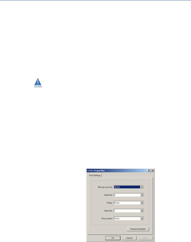
1.4.2Console Setup
Connect the console port on the switch to the serial port on the computer using the serial cable listed above. The settings for the HyperTerminal firmware emulating a VT100 are shown below. Make sure the serial parameters are set as shown (or bps = 38400, data bits = 8, parity = none, stop bits = 1, flow control = none).
FIGURE 1–1: Serial Settings in HyperTerminal
MULTILINK ML1200 MANAGED FIELD SWITCH – INSTRUCTION MANUAL |
1–7 |
INTRODUCTION |
CHAPTER 1: INTRODUCTION |
1.4.3Console Screen
Once the console cable is connected to the PC and the firmware configured, ML1200 legal disclaimers and other text scrolls by on the screen.
The line interface prompt appears displaying the switch model number (e.g. ML1200>)
The switch has three modes of operation: operator (least privilege), manager, and configuration. The prompts for the switches change as the switch changes modes from operator to manager to configuration. The prompts are shown below with a brief description.
•ML1200>
Operator Level - for running operations queries
•ML1200#
Manager Level - for setting and reviewing commands
•ML1200##
Configuration Level - for changing the switch parameter values
For additional information on default users, user levels and more, refer to section 1.4.8 -
User Management.
1.4.4Logging In for the First Time
For the first time, use the default user name and passwords assigned by GE. They are:
•Username: manager Password: manager
•Username: operator Password: operator
We recommend you login as manager for the first time to set up the IP address as well as change user passwords or create new users.
1.4.5Automatic IP Address Configuration
The ML1200 is operational immediately after it is powered up. The advanced management and configuration capabilities of the ML1200 allows you to easily configure, manage, and secure your devices and network.
Before starting, ensure you have the following items:
•RJ45 Ethernet cable
•PC with an Ethernet port
•Microsoft Internet Explorer 6.0 or higher
•Macromedia Flash Player 5.0 or higher (available from http:// www.macromedia.com/shockwave/download/ download.cgi?P1_Prod_Version=ShockwaveFlash)
Ensure both firmware components are installed before proceeding.
The ML1200 can search the network for commonly used services that can issue an IP address. If the switch is connected to a network, the ML1200 uses the following process to find an IP address.
1–8 |
MULTILINK ML1200 MANAGED FIELD SWITCH – INSTRUCTION MANUAL |

CHAPTER 1: INTRODUCTION |
INTRODUCTION |
If the ML1200 is not connected to a network, then proceed to Step 3 below. or use the default IP address.
Step 1:
The ML1200 will scan the network for a DHCP server. If the server responds, the ML1200 will acquire and set the assigned IP address. To manage the switch, determine the assigned IP address and enter as follows in Internet Explorer:
https://<assigned_IP_address>
Ensure that https is entered, not http, and that there is connectivity (that is, you can ping the switch).
Step 2:
If there is no response from a DCHP server, the ML1200 will query for a BOOTP server. If the server responds, the ML1200 will acquire and set the assigned IP address. To manage the switch, determine the assigned IP address and enter as follows in Internet Explorer:
https://<assigned_IP_address>
Ensure that https is entered, not http, and that there is connectivity (that is, you can ping the switch).
Step 3:
If there is no response from either a DCHP or BOOTP server, or if the switch is not connected to a network, the switch will assign itself an IP address. The ML1200 will check to see if IP address 192.168.1.2, with a network mask of 255.255.255.0, is free. If so, it will assume these values. If this IP address is assigned to another device, the ML1200 will repeat steps 1 through 3 to find a DCHP or BOOTP server or wait for the 192.168.1.2 address to become free.
Once connected, the browser will display a login prompt. The default login is:
•Username: manager Password: manager
1.4.6Setting the IP Parameters Using Console Port
To configure the Switch’s IP using EnerVista UR Setup software, refer to chapter 2 of this manual,
To setup the switch, the IP address and other relevant TCP/IP parameters have to be specified.
The IP address on the MultiLink ML1200 Managed Field Switch is set to 192.168.1.2 from the factory. The switch is fully operational as a Layer 2 switch as a default. Setting a default IP address can potentially cause duplicate IP address problem if multiple switches are powered on and installed on the network. To manage the switch, an IP address has to be programmed.
Before starting, please ensure that the IP address assigned to the switch is known or contact your system/network administrator to get the IP address information. Follow the steps listed below to configure the switch.
Z Ensure the power is off.
MULTILINK ML1200 MANAGED FIELD SWITCH – INSTRUCTION MANUAL |
1–9 |

INTRODUCTION |
CHAPTER 1: INTRODUCTION |
ZFollow the steps described above for connecting the console cable and setting the console firmware.
ZPower on the switch.
ZOnce the login prompt appears, login as manager using default password (manager).
ZConfigure the IP address, network mask and default gateway as per the IP addressing scheme for your network.
ZSet the manager password (this step is recommended; refer to the following section).
ZSave the settings (without saving, the changes made will be lost).
ZPower off the switch (or a firmware reboot as discussed below).
ZPower on the switch - login with the new login name and password.
ZFrom the PC (or from the switch) ping the IP address specified for the switch to ensure connectivity.
ZFrom the switch ping the default gateway specified (ensure you are connected to the network to check for connectivity) to ensure network connectivity.
Syntax:
ipconfig [ip=<ip-address>] [mask=<subnet-mask>] [dgw=<gateway>]
An example is shown below.
ML1200# ipconfig ip=3.94.247.41 mask=255.255.252.0 dgw=3.94.244.41
ML1200# save
This manual assumes the reader is familiar with IP addressing schemes as well as how net mask is used and how default gateways and routers are used in a network.
Reboot gives an opportunity to save the configuration prior to shutdown. For a reboot, simply type in the command reboot. Note that even though the passwords are not changed, they can be changed later.
ML1200# reboot
Proceed on rebooting the switch? ['Y' or 'N'] Y
Do you wish to save current configuration? ['Y' or 'N'] Y
ML1200#
The ML1200 forces an answer by prompting with a “Y” or a “N” to prevent accidental keystroke errors and loss of work.
The parameters can be viewed at any time by using the show command. The show command will be covered in more detail later in various sections throughout the document.
The example below illustrates the basic setup parameters. You can use show setup or show sysconfig commands to view setup parameters.
1–10 |
MULTILINK ML1200 MANAGED FIELD SWITCH – INSTRUCTION MANUAL |
CHAPTER 1: INTRODUCTION INTRODUCTION
ML1200# show setup
Version: ML1200 build 2.1.0 Nov 12 2007 11:10:13
MAC Address: 00:20:06:27:0a:e0
IP Address: 3.94.247.41
Subnet Mask: 255.255.252.0
Gateway Address: 3.94.244.1
CLI Mode: Manager
System Name: ML1200
System Description: 6 Port Modular Ethernet Switch
System Contact: multilin.tech@ge.com
System Location: Markham, Ontario
System ObjectId: 1.3.6.1.4.1.13248.12.7
ML1200# show sysconfig
System Name: ML1200
System Contact: multilin.tech@ge.com
System Location: Markham, Ontario
Boot Mode: manual
Inactivity Timeout(min): 120
Address Age Interval(min): 300
Inbound Telnet Enabled: Yes
Web Agent Enabled: Yes
Time Zone: GMT-05hours:00minutes
Day Light Time Rule: Canada
System UpTime: 0 Days 0 Hours 45 Mins 55 Secs
ML1200#
Some of the parameters in the MultiLink ML1200 Managed Field Switch are shown above. The list of parameters below indicates some of the key parameters on the switch and the recommendations for changing them (or optionally keeping them the same).
1.4.7Privilege Levels
Two privilege levels are available - manager and operator. Operator is at privilege level 1 and the manager is at privilege level 2 (the privilege increases with the levels). For example, to set up a user for basic monitoring capabilities use lower number or operator level privilege (level 1).
The Manager level provides all operator level privileges plus the ability to perform systemlevel actions and configuration commands. To select this level, enter the enable <username> command at the Operator level prompt and enter the Manager password, when prompted.
enable <user-name>
For example, switching from an operator-level to manager-level, using the enable command is shown below.
ML1200> enable manager
Password: *******
ML1200#
Note the prompt changes with the new privilege level.
Operator privileges allow views of the current configurations but do not allow changes to the configuration. A “>” character delimits the operator-level prompt.
Manager privileges allow configuration changes. The changes can be done at the manager prompt or for global configuration as well as specific configuration. A “#” character delimits any manager prompt.
MULTILINK ML1200 MANAGED FIELD SWITCH – INSTRUCTION MANUAL |
1–11 |
INTRODUCTION |
CHAPTER 1: INTRODUCTION |
1.4.8User Management
A maximum of five users can be added per switch. Users can be added, deleted or changed from a manager level account. There can be more than one manager account, subject to the maximum number of users on the switch being restricted to five.
To add a user, use the add command as shown below. The user name has to be a unique name. The password is recommended to be at least 8 characters long with a mix of upper case, lower case, numbers and special characters.
add user=<name> level=<number>
The following example adds a user “peter” with manager-level privilege:
ML1200# user
ML1200(user)## add user=peter level=2
Enter User Password:******
Confirm New Password:******
ML1200(user)##
To delete a user, use the delete command as shown below. delete user=<name>
The following example deletes the user “peter”:
ML1200(user)## delete user=peter
Confirm User Deletion(Y/N): Y
User successfully deleted
ML1200(user)##
The syntax to modify a password is shown below: passwd user=<name>
The following example changes the password for user “peter”.
ML1200(user)## passwd user=peter
Enter New Password:******
Confirm New Password :******
Password has been modified successfully
ML1200(user)##
The syntax to modify the privilege level for a specific user is shown below: chlevel user=<name> level=<number>
The following example modifies the privilege level of user “peter” to Operator privileges.
ML1200(user)## chlevel user=peter level=1
Access Permission Modified
ML1200(user)##
The syntax to set the access privileges for telnet and Web services is shown below: useraccess user=<name> service=<telnet|web> <enable|disable>
The following example sets the access privileges for telnet and Web services.
ML1200(user)## useraccess user=peter service=telnet disable
Telnet Access Disabled.
1–12 |
MULTILINK ML1200 MANAGED FIELD SWITCH – INSTRUCTION MANUAL |
CHAPTER 1: INTRODUCTION |
INTRODUCTION |
1.4.9Help
Typing the help command lists the commands you can execute at the current privilege level. For example, typing help at the Operator level shows the following:
ML1200> help
logout |
ping |
set |
terminal |
telnet |
walkmib |
Contextless Commands:
!? clear
enable |
exit |
help |
show |
whoami |
|
alarm |
|
|
ML1200>
Help for any command that is available at the current context level can be viewed by typing help followed by enough of the command string to identify the command. The following syntax applies:
help <command string>
For example, to list the help for the set time command
ML1200# help set time
set time |
: Sets the device Time |
Usage
set time hour=<0-23> min=<0-59> sec=<0-59> [zone=GMT[+/-]hh:mm]
ML1200#
The options for a specific command can be displayed by typing the command and pressing enter. The following syntax applies:
command <Enter>
For example, the options for the show command are:
ML1200# show <Enter>
Usage
show active-stp show active-snmp show active-vlan show address-table show age
show alarm show arp
show auth <config|ports> show backpressure
show bootmode --more--
Other ways to display help, specifically, with reference to a command or a set of commands, use the TAB key. The following syntax applies:
<TAB>
<Command string> <TAB>
<First character of the command> <TAB>
For example, following the syntax listed above, the <TAB> key will list the available commands in the particular privilege level:
ML1200> <TAB>
MULTILINK ML1200 MANAGED FIELD SWITCH – INSTRUCTION MANUAL |
1–13 |
INTRODUCTION |
CHAPTER 1: INTRODUCTION |
?
alarm clear enable exit help logout ping set show telnet
terminal walkmib whoami
ML1200>
The following example lists commands starting with a specific string:
ML1200> s <TAB>
set show
ML1200>
In the following example, the <TAB> key completes the command:
ML1200> se<TAB>
password timeout vlan
ML1200> set
1.4.10 Exiting
To exit from the CLI interface and terminate the console session use the logout command. This command prompts to ensure that the logout was not mistakenly typed. The following syntax applies:
logout
The following example illustrates logging out from a session:
ML1200> logout
Logging out from the current session [’Y’ or ’N’] Y
Connection to the host lost
1–14 |
MULTILINK ML1200 MANAGED FIELD SWITCH – INSTRUCTION MANUAL |
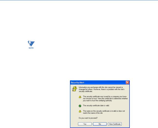
CHAPTER 1: INTRODUCTION |
INTRODUCTION |
1.5EnerVista Secure Web Management
1.5.1Logging in for the First Time
Enter the following URL in the web browser to login to the EnerVista Secure Web
Management software.
https://<IP Address assigned to the switch>
Make sure you use HTTPS (secure HTTP) and not HTTP in the URL.
In the example shown in the previous section, the URL is:
https://3.94.247.41
If your site uses name services, you can use a name instead of the IP address. Please make sure that the name is resolved to the IP address assigned to the switch.
The secure site will issue the certificate check shown below.
FIGURE 1–2: Security certificate
Once you click Yes on the security certificate, the browser will prompt you to login.
MULTILINK ML1200 MANAGED FIELD SWITCH – INSTRUCTION MANUAL |
1–15 |
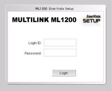
INTRODUCTION |
CHAPTER 1: INTRODUCTION |
FIGURE 1–3: Login screen
For the first time,
ZLogin with the name manager and password manager.
ZClick on Login.
After a successful login, the welcome screen is shown. Note the different information provided on the screen and different areas. The menus are used to configure settings on the switch. Users can click on a specific port to open the port configuration view.
1–16 |
MULTILINK ML1200 MANAGED FIELD SWITCH – INSTRUCTION MANUAL |
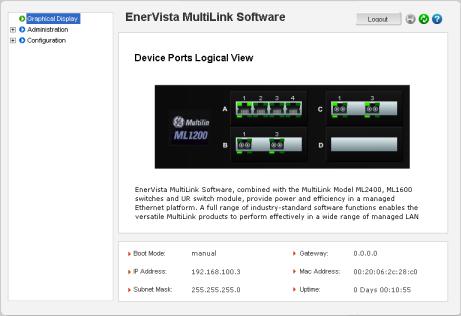
CHAPTER 1: INTRODUCTION |
INTRODUCTION |
FIGURE 1–4: Welcome screen
1.5.2Privilege Levels
•Operator privilege users: operator privileges allow views of the current configurations but do not allow changes to the configuration.
•Manager privilege users: manager privileges allow configuration changes. The changes can be done at the manager prompt or for global configuration as well as specific configuration.
1.5.3User Management
A maximum of five users can be added per switch. Users can be added, deleted or changed from a manager level account. There can be more than one manager account, subject to the maximum number of users on the switch being restricted to five.
ZSelect the Administration > User Mgmt > User Accounts menu item.
ZTo add a user, use the add button.
The username must be a unique name. The password is recommended to be at least 8 characters long with a mix of upper case, lower case, numbers and special characters.
MULTILINK ML1200 MANAGED FIELD SWITCH – INSTRUCTION MANUAL |
1–17 |
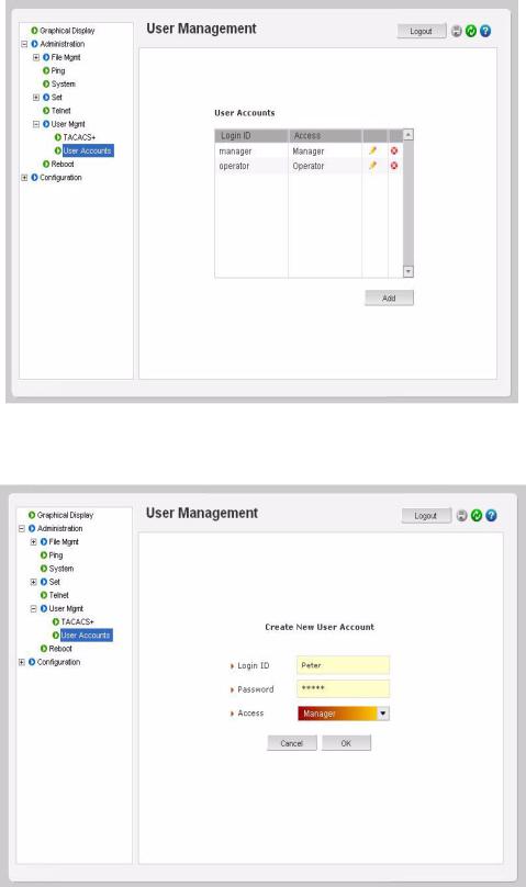
INTRODUCTION |
CHAPTER 1: INTRODUCTION |
In the following example below, the user peter was added with manager privilege after clicking the add button.
1–18 |
MULTILINK ML1200 MANAGED FIELD SWITCH – INSTRUCTION MANUAL |
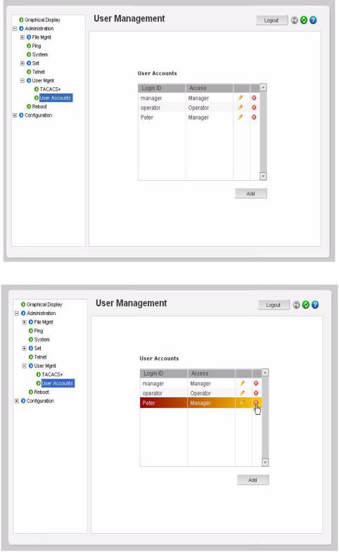
CHAPTER 1: INTRODUCTION |
INTRODUCTION |
After successfully adding a user, the added user is displayed in the list of users as shown below.
Z To delete a user, click on the delete icon ( )as shown below.
MULTILINK ML1200 MANAGED FIELD SWITCH – INSTRUCTION MANUAL |
1–19 |
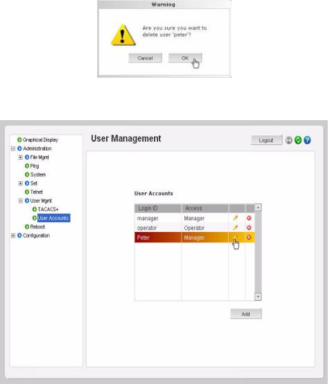
INTRODUCTION |
CHAPTER 1: INTRODUCTION |
The firmware will prompt to verify the delete command.
ZTo modify the password, view the users as described above and click on the edit icon (  ).
).
1–20 |
MULTILINK ML1200 MANAGED FIELD SWITCH – INSTRUCTION MANUAL |
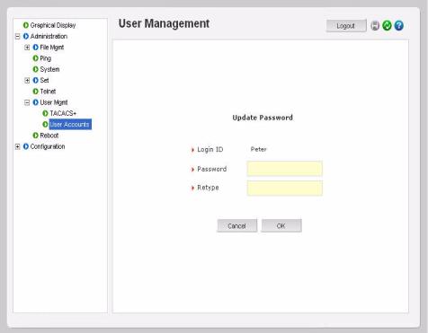
CHAPTER 1: INTRODUCTION |
INTRODUCTION |
After clicking on the edit icon, the screen opens up for modifying the password.
In this example, the user ID peter was selected for modification. The password for peter will be modified after the new password is entered.
1.5.4Modifying the Privilege Level
Privilege levels cannot be changed from the EnerVista Secure Web Management (SWM) firmware. This can only be done through the CLI interface, or alternately, by deleting the user and adding the same user with the proper privilege level.
MULTILINK ML1200 MANAGED FIELD SWITCH – INSTRUCTION MANUAL |
1–21 |

INTRODUCTION |
CHAPTER 1: INTRODUCTION |
1.5.5Help
Help for the EnerVista Secure Web Management software can be obtained by clicking on the Help icon as shown below.
1.5.6Exiting
Z To exit or logout, click on the logout button.
1–22 |
MULTILINK ML1200 MANAGED FIELD SWITCH – INSTRUCTION MANUAL |
Loading...