


Installation |
Pyramid Wall |
Instructions |
Chimney Vent Hoods |
JVW5301, JVW5361 |


 “If you have questions, call 800.GE.CARES (800.432.2737) or visit our website at: GEAppliances.com”
BEFORE YOU BEGIN
Read these instructions completely and carefully.
• IMPORTANT ³Save these instructions for local inspector’s use.
• IMPORTANT ³ Observe all governing codes and ordinances.
•Note to Installer – Be sure to leave these instructions with the Consumer.
•Note to Consumer – Keep these instructions for future reference.
•Skill level – Installation of this vent hood requires basic mechanical and electrical skills.
•Completion time – Approximately 1 to 3 hours
•Proper installation is the responsibility of the installer.
•Product failure due to improper installation is not covered under the Warranty.
 CAUTION: Due to the weight and size of these vent hoods and to reduce the risk of personal injury or damage to the product, TWO
PEOPLE ARE REQUIRED FOR PROPER INSTALLATION.
FOR YOUR SAFETY:
 WARNING: Before beginning the installation, switch power off at service panel and lock the service disconnecting means to prevent power from being switched on accidentally. When the service disconnecting means cannot be locked, securely fasten a prominent warning device, such as a tag, to the service panel.
 WARNING: TO REDUCE THE RISK OF FIRE, ELECTRIC SHOCK OR INJURY TO PERSONS, OBSERVE THE FOLLOWING:
A.Installation work and electrical wiring must be done by qualified person(s) in accordance with all applicable codes and
standards, including fire-rated construction.
B.Sufficient air is needed for proper combustion and exhausting of gases through the flue (chimney) of fuel burning equipment to prevent back drafting. Follow the heating equipment manufacturer’s guidelines and safety standards such
as those published by the National Fire Protection Association (NFPA), the American Society for Heating, Refrigeration and Air Conditioning Engineers (ASHRAE) and the local code authorities.
C.When cutting or drilling into wall or ceiling, do not damage electrical wiring and other hidden utilities.
D.Ducted fans must always be vented to the outdoors.
E.Turn off breaker to adjacent rooms while working.
 WARNING: TO REDUCE THE RISK OF FIRE, USE ONLY METAL DUCT WORK.
INSTRUCTIONS INSTALLATION
(991.0364.803 rev 2) 31-10983-1 04-15 GE
INSTALLATION PREPARATION
Installation Preparation
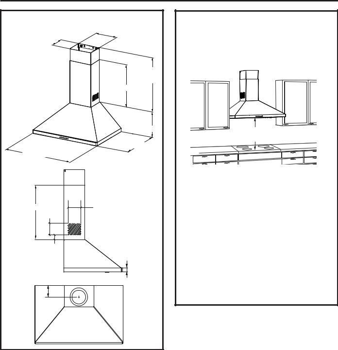
PRODUCT DIMENSIONS |
|
|
8-1/4” |
7-1/16” |
|
|
17-3/8” Min. |
|
24-7/16" Max. |
|
13” |
|
10-1/8” |
|
18-1/2” |
30” to 36” |
|
13” |
5” |
3-5/16” |
|
2” |
|
|
1-3/8” |
4-1/4” |
|
INSTALLATION CLEARANCES
These vent hoods are designed to be installed onto a wall with no above cabinets.
•Install these hoods between the required 24” minimum and 36” recommended maximum above the cooking surface.
24” Required Min.
36” Recommended Max.
The vent hood must be installed between the required 24” minimum and recommended 36” maximum above the cooking surface. The hood installation height above the cooking surface depends upon ceiling height and duct cover limitations. The telescopic duct cover conceals the ductwork running from the top of the hood to the ceiling. For supplied duct cover ceiling heights, see table on page 5.
NOTE: Installation height should be measured from the cooking surface to the lowest part of the hood. This hood must be installed onto a wall. It can be vented to the outdoors, or it
can be installed for recirculating operation. For recirculation operation, see Recirculation Install Planning.
2 |
31-10983 |
Installation Preparation
ADVANCE PLANNING
Duct Install Planning
•This hood is designed to be vented vertically through the ceiling. Use a 6" round duct. Use locally supplied elbows to vent horizontally through the rear wall.
•Use metal ductwork only.
•Determine the exact location of the vent hood.
•Plan the route for venting exhaust to the outdoors. To maximize the ventilation performance of the vent system:
1.Minimize the duct run length and number of transitions and elbows.
2.Maintain a constant duct size.
3.Seal all joints with duct tape to prevent any leaks.
4.Do not use any type of flexible ducting.
•Install a wall cap or roof cap with damper at the exterior opening. Purchase the wall or
roof cap and any transition and length of duct needed in advance.
•When applicable, install any makeup (replacement) air system in accordance with local building code requirements. Visit GEAppliances.com for available makeup air solutions.
Recirculation Install Planning
A recirculation duct (included) and two charcoal filters (not included) are necessary for recirculation installation.
Power Supply Planning
The location of the power supply connection is called out in the Prepare the Wall section on page 6.
POWER SUPPLY
IMPORTANT – (Please read carefully)
 WARNING:
FOR PERSONAL SAFETY, THIS APPLIANCE MUST BE PROPERLY GROUNDED.
Remove house fuse or open circuit breaker before beginning installation.
Do not use an extension cord or adapter plug with this appliance. Follow National Electrical Codes or prevailing local codes and ordinances.
Electrical supply
These vent hoods must be supplied with 120V, 60Hz, and connected to an individual, properly grounded branch circuit, and protected by a 15 or 20 amp circuit breaker or time delay fuse.
•Wiring must be 2 wire with ground.
•If the electrical supply does not meet the above requirements, call a licensed electrician before proceeding.
•Route house wiring as close to the installation location as possible in the ceiling or wall.
•Connect the wiring to the house wiring in accordance with local codes.
Grounding instructions
The grounding conductor must be connected to a ground metal, permanent wiring system, or an
equipment-grounding terminal or lead on the hood.
 WARNING: The improper connection of the equipment-grounding conductor can result in a risk of electric shock. Check with a qualified electrician or service representative if you are in doubt whether the appliance is properly grounded.
PREPARATION INSTALLATION
31-10983 |
3 |
INSTALLATION PREPARATION
Installation Preparation
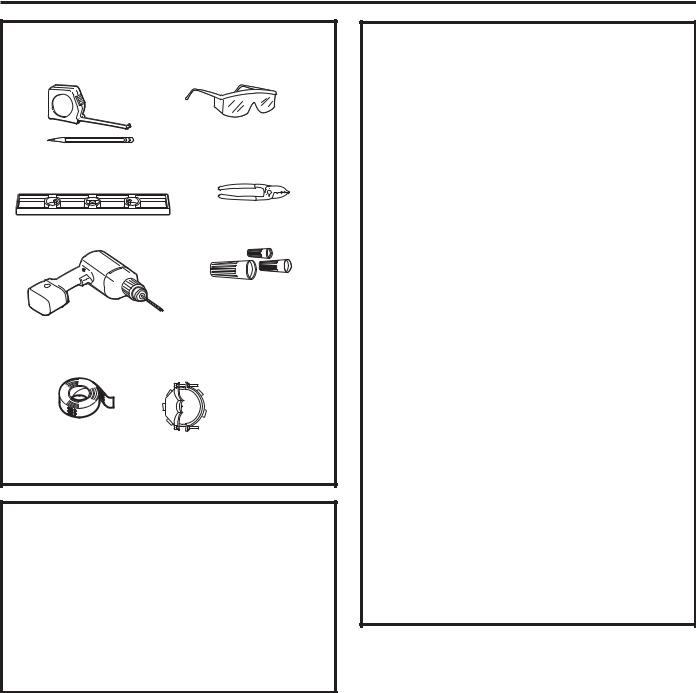
TOOLS AND MATERIALS REQUIRED |
|
(NOT SUPPLIED) |
|
|
Safety glasses |
Pencil and tape measure |
|
Spirit level |
Wire cutter/stripper |
|
|
|
UL listed wire nuts |
Electric drill, #2 Phillips, |
|
flat head, and 9/32" drill bit |
|
Aluminized |
Strain relief for |
Duct tape |
|
|
junction box |
REMOVE THE PACKAGING
 CAUTION: Wear gloves to protect against sharp edges.
•Remove the duct covers.
•Remove the hardware bag, literature package and other boxed parts.
•Remove and properly discard the protective plastic wrapping and other packaging materials.
PLAN THE INSTALLATION
 CAUTION: To reduce risk of fire and to properly exhaust air, be sure to duct the air outside – Do not vent exhaust air into spaces within walls or ceilings or into attics, crawl spaces, or garages.
PARTS SUPPLIED FOR INSTALLATION
•1 Hardware Package
•1 Literature Package
PARTS NEEDED FOR INSTALLATION
•1 Strain Relief
•Power Supply Cable
•1 Wall or Roof Cap (for external venting only)
•All Metal Ductwork (for external venting only)
•Recirculation Duct (for recirculation install only)
 WARNING:
PERSONAL INJURY HAZARD
Because of the weight and size of the range hood canopy. It is recommended that 2 people are used to install the range hood. Failure to properly lift range hood could result in damage to the product or personal injury.
NOTE: This range hood can be installed as either ducted or recirculation. In a ducted application, this range hood can be vented through the wall or ceiling. When installed for recirculation, the range hood vents out the sides of the duct cover.
NOTE: Before making any cuts or holes for installation, determine which venting method will be used and carefully calculate all measurements.
4 |
31-10983 |

Installation Preparation
RANGE HOOD COMPONENTS |
|
|||
A. Canopy Section |
F. Duct Cover Screws |
|||
B. Lower Duct Cover |
G. Damper |
|
||
C. Upper Duct Cover |
H. Canopy Mounting |
|||
D. Mounting Screws |
Anchors |
|
||
E. Duct Cover |
|
I. Duct Cover Anchors |
||
Mounting Brackets |
|
|
||
|
I |
|
D |
|
|
|
|
F |
|
E |
F |
|
|
|
|
I |
|
C |
|
|
|
D |
|
|
|
|
|
|
|
|
|
|
B |
|
|
|
|
H |
|
|
I |
|
|
|
|
|
|
G |
D |
|
|
|
|
|
|
A |
D |
|
|
|
|
|
|
|
RANGE HOOD RECIRCULATION
COMPONENT
Recirculation Duct
INSTALLATION DIMENSIONS
The Pyramid Chimneys are adjustable and designed to meet varying ceiling heights. The duct covers can be adjusted for ceilings between
7’ 3 1/4” and 8’ 10 5/16” depending on the distance between the bottom of the hood and the cooktop (distance X).
|
|
|
|
|
|
|
|
|
|
|
|
|
Upper Duct Cover |
|
|
|
|||
|
|
|
|
|
|
|
|
|
|
|
|
||||||||
|
|
|
|
|
|
|
|
|
|
|
|
|
|
|
|
Required Min & |
Recommended |
|
|
|
4-3/8 ”min |
|
|||||||||||||||||
|
|
|
|
|
|
|
|
|
Max Ceiling Height Examples |
|
|||||||||
11-7/16” max |
|
|
|
|
|
|
|
|
|
||||||||||
|
|
|
|
|
|
|
|
|
|
|
|
||||||||
|
|
|
|
|
|
|
|
|
|
|
|
|
|
|
|
x = 24" |
|
x = 36" |
|
|
|
|
|
|
|
|
|
|
|
|
|
|
|
|
|
|
|||
|
|
|
|
|
|
|
|
|
|
|
|
|
|
|
|||||
|
|
|
|
|
|
|
|
|
|
|
|
|
|
|
|
Min |
|
Min |
|
|
|
|
|
|
|
|
|
|
|
|
|
|
7' 3-1/4" |
8' 3-1/4" |
|
||||
|
|
|
13” |
|
|
||||||||||||||
|
|
|
|
|
|
|
|
|
|
|
Max |
|
Max |
|
|||||
|
|
|
|
|
|
|
|
|
|
|
|
|
|
|
|
|
|
||
|
|
|
|
|
|
|
|
|
|
|
|
|
7' 10-5/16" |
|
8’ 10-5/16" |
|
|||
|
|
|
|
|
|
|
|
|
|
|
|
|
Lower Duct Cover |
For higher ceiling |
|||||
|
|
|
|
|
|
|
|
|
|||||||||||
|
|
|
|
|
|
|
|
|
|
|
|
|
|
|
|
|
|||
|
|
|
|
|
|
|
|
|
|
|
|
|
|
|
|
|
|||
|
|
|
|
|
|
|
|
|
|
|
|
|
|
|
|
|
installations, the |
||
|
|
9-7/8” |
|
|
|
|
|
|
|
|
|
|
|
||||||
|
|
|
|
|
Canopy |
High Ceiling |
|||||||||||||
|
|
|
|
|
|
|
|
|
|
||||||||||
|
|
|
|
|
|
|
|
|
|
Duct Cover Kit |
|||||||||
|
|
|
|
|
|
|
|
|
|
|
|
|
|
|
|
|
(JXDC72) includes |
||
|
|
|
|
|
|
|
|
|
|
|
|
|
|
|
|
|
a new 20” lower |
||
|
|
|
|
|
|
|
|
|
|
|
18-1/2” |
|
|||||||
|
|
|
|
|
|
|
|
|
X = Distance From Hood To Cooktop |
duct cover which |
|||||||||
|
|
|
|
|
|
|
|
|
would replaces |
||||||||||
|
|
|
|
|
|
|
|
|
|
(Varies depending on installation) |
the 13” lower duct |
||||||||
|
|
|
|
X |
|
|
|
|
|
|
Required Min - 24”, |
||||||||
|
|
|
|
|
|
|
cover that came |
||||||||||||
|
|
|
|
|
|
|
|
|
|
Recommended Max - 36” |
|||||||||
|
|
|
|
|
|
|
|
|
|
||||||||||
|
|
|
|
|
|
|
|
|
|
with the hood. |
|||||||||
|
|
|
|
|
|
|
|
|
|
|
also consult cooktop |
||||||||
|
|
|
|
|
|
|
|
|
|
manufacturer’s recommendation |
|
|
|
||||||
|
|
|
|
|
|
|
|
|
|
|
|
|
|
|
|
|
|
|
|
19-3/4”
36”
HARDWARE COMPONENTS
D F H I
PREPARATION INSTALLATION
31-10983 |
5 |
 Loading...