


Installation
Instructions
2YHU WKH 5DQJH 0LFURZDYH 2YHQ
AVM4160, JNM3161, JVM3160, and RVM5160
Questions? Call 800.GE.CARES (800.432.2737) or Visit our Website at: GEAppliances.com
BEFORE YOU BEGIN
Read these instructions completely and carefully. |
Note to Consumer – Keep these instructions |
||
|
IMPORTANT – Save these |
for future reference. |
|
6NLOO OHYHO – Installation of this appliance requires basic |
|||
|
instructions for local inspector’s use. |
mechanical and electrical skills. |
|
|
IMPORTANT – Observe all |
||
Proper installation is the responsibility of the installer. |
|||
|
governing codes and ordinances. |
Product failure due to improper installation is not |
|
Note to Installer – Be sure to leave these |
covered under the warranty. |
||
instructions with the consumer.
Convenience |
Cooking |
|
||||||
|
|
|
||||||
|
|
|
|
age |
to |
|||
|
n |
|
Be |
|
age |
|
|
|
|
|
Bever |
|
|
|
|
||
Popcorn |
|
|
|
|
|
|
|
|
|
|
|
|
f |
|
|
CookC |
|
|
|
|
Defrost |
Time |
||||
|
att |
|
Weight/Time |
Time |
||||
Rehea |
|
Weight/Time |
|
|
||||
|
|
|
|
|
|
|
r |
|
|
|
|
|
|
|
|
TimeTi |
r |
|
|
|
|
|
|
|
On/Offff |
|
Express |
Cook |
|
|
On/O |
|
|||
|
|
|
|
|||||
|
|
|
|
3 |
AddAdd |
|
||
|
|
|
|
30 .. |
||||
1 |
|
2 |
|
30Sec |
||||
|
|
|
|
|
|
|
||
4 |
|
5 |
|
6 |
Turntable |
|||
|
|
|
|
|||||
|
|
|
|
|
Surface |
|||
|
|
|
|
|
|
|
||
|
|
|
|
9 |
Surface |
|||
7 |
|
8 |
|
Light |
||||
|
|
|
|
|
|
|
||
|
|
|
|
SettSe |
Vent |
|
||
Power |
|
0 |
|
|
|
ck |
Vent |
|
Power |
|
|
Clock |
|
|
|||
LevelLevel |
|
|
|
|
|
|
|
|
|
l |
|
SSttaart |
|
|
|||
ncel |
|
Pause |
|
|
|
|||
Ca |
|
|
|
|
|
|||
OfffOf |
|
|
Pause |
|
|
|||
Throughout this manual, features and appearance may vary from your model.
READ CAREFULLY. KEEP THESE INSTRUCTIONS.
49-40675-2
(12-13 GE)
Installation Instructions
CONTENTS |
|
|
General information |
|
|
Important Safety Instructions........................................ |
3 |
|
Electrical Requirements .................................................. |
3 |
|
Tools You Will Need ......................................................... |
4 |
|
Hood Exhaust ................................................................. |
5,6 |
|
'DPDJH ² 6KLSPHQW ,QVWDOODWLRQ .................................. |
7 |
|
Parts Included ................................................................... |
7 |
|
0RXQWLQJ 6SDFH................................................................ |
8 |
|
6WHS E\ VWHS LQVWDOODWLRQ JXLGH |
|
|
3ODFHPHQW RI 0RXQWLQJ 3ODWH................................... |
9-11 |
|
|
Removing the Mounting Plate............................. |
9 |
|
Finding the Wall Studs.......................................... |
9 |
|
Determining Mounting Plate Location .............. |
10 |
|
Aligning the Mounting Plate .............................. |
11 |
Installation Types ..................................................... |
12-23 |
|
A |
Recirculating.................................................. |
13-16 |
|
Attach Mounting Plate to Wall ................ |
13 |
|
Preparation of Top Cabinet...................... |
13 |
|
Adjust the Blower...................................... |
14 |
|
Installing the Charcoal Filter.................... |
15 |
|
Mount the Microwave Oven .............. |
15, 16 |
|
Installing the Charcoal Filter |
|
|
without Top Access ............................ |
16 |
B |
Outside Top Exhaust..................................... |
17-20 |
|
Attach Mounting Plate to Wall ................. |
17 |
|
Preparation of Top Cabinet....................... |
18 |
|
Adjust Blower Motor .................................. |
18 |
|
Assemble and Install Adaptor .................. |
19 |
|
Mount the Microwave Oven .............. |
19, 20 |
|
Connecting Ductwork................................ |
20 |
C Outside Back Exhaust.................................. |
21-24 |
Installation Overview ................................ |
21 |
Preparing Rear Wall for |
|
Outside Back Exhaust................................ |
21 |
Attach Mounting Plate to Wall .......... |
21, 22 |
Preparation of Top Cabinet....................... |
22 |
Adapting Blower for Outside |
|
Back Exhaust.......................................... |
22, 23 |
Mount the Microwave Oven .............. |
23, 24 |
%HIRUH <RX 8VH <RXU 0LFURZDYH 2YHQ ..................... |
25 |
2
Installation Instructions
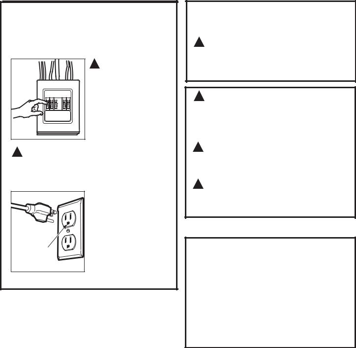
IMPORTANT SAFETY INSTRUCTIONS
A qualified electrician must perform a ground continuity check on the wall receptacle before beginning the installation to ensure that the outlet box is properly grounded. If not properly grounded, or if the wall receptacle does not meet electrical requirements noted (under ELECTRICAL REQUIREMENTS), a qualified electrician should be employed to correct any deficiencies.
 WARNING:
5LVN RI (OHFWULF 6KRFN
Can cause injury or death:
5HPRYH KRXVH IXVH RU RSHQ FLUFXLW EUHDNHU EHIRUH EHJLQQLQJ LQVWDOODWLRQ WR DYRLG VHYHUH RU IDWDO VKRFN LQMXU\
 WARNING:5LVN RI (OHFWULF 6KRFN
Can cause injury or death: THIS APPLIANCE MUST BE PROPERLY GROUNDED WR DYRLG VHYHUH RU IDWDO VKRFN
120 V Models |
|
|
The power cord of this |
|
appliance is equipped with |
|
D WKUHH SURQJ JURXQGLQJ |
|
SOXJ ZKLFK PDWHV ZLWK |
|
D VWDQGDUG WKUHH SURQJ |
|
JURXQGLQJ ZDOO UHFHSWDFOH |
Ensure proper |
to minimize the possibility |
ground exists |
RI HOHFWULF VKRFN KD]DUG |
before use. |
from this appliance. |
:KHUH D VWDQGDUG WZR SURQJ ZDOO UHFHSWDFOH LV encountered, it must be replaced with a properly
JURXQGHG WKUHH SURQJ ZDOO UHFHSWDFOH LQVWDOOHG E\ D qualified electrician.
 WARNING:5LVN RI (OHFWULF 6KRFN
Can cause injury or death: DO NOT, under any
FLUFXPVWDQFHV FXW GHIRUP RU UHPRYH DQ\ RI WKH SURQJV from the power cord. Do not use with an extension cord. Failure to comply may cause fire.
 CAUTION:For personal safety, the
PRXQWLQJ VXUIDFH PXVW EH FDSDEOH RI VXSSRUWLQJ WKH FDELQHW ORDG LQ DGGLWLRQ WR WKH DGGHG ZHLJKW RI WKLV² SRXQG SURGXFW SOXV DGGLWLRQDO PLFURZDYH RYHQ
ORDGV RI XS WR SRXQGV RU D WRWDO ZHLJKW RI ² pounds.
 CAUTION:For personal safety, this product
FDQQRWEHLQVWDOOHGLQFDELQHWDUUDQJHPHQWVVXFKDVDQ island or a peninsula. It must be mounted to BOTH a top
FDELQHW $1' D EDFN ZDOO
 CAUTION:7R DYRLG WKH ULVN RI SHUVRQDO LQMXU\ EDFN LQMXU\ RU RWKHU LQMXULHV GXH WR H[FHVVLYH ZHLJKW RI WKH PLFURZDYH RU SURSHUW\ GDPDJH \RX ZLOO QHHG WZR SHRSOH WR LQVWDOO WKLV PLFURZDYH
ELECTRICAL REQUIREMENTS
120 V Models
This product requires a three-prong grounded outlet. Product rating is 120 volts AC, 60 Hertz, 15 amps, and 1.70 kilowatts. This product must be connected to a supply circuit of the proper voltage and frequency. Wire size must conform to the requirements of the National Electrical Code or the prevailing local code for this kilowatt rating. The power supply cord and plug should be brought to a separate 15 to 20 ampere branch circuit single grounded outlet. The outlet box should be located in the cabinet above the microwave oven and away from any potential microwave ducting. The outlet box and supply circuit should be installed by a qualified electrician and conform to the National Electrical Code or the prevailing local code.
3
Installation Instructions
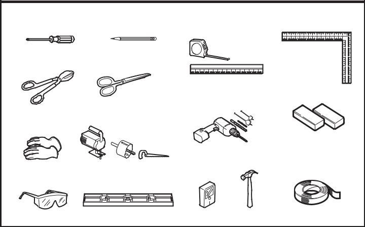
TOOLS YOU WILL NEED
#1 and #2 Phillips |
Pencil |
Carpenter square |
screwdriver |
|
(optional) |
Ruler or tape measure and straight edge
Scissors (to cut
Tin snips (for cutting template, if necessary) damper, if required)
Electric drill with 3ø16s, 7ø16s, 1ø2s and 5ø8s drill bits
Gloves |
Saw (saber, hole or keyhole) |
Filler blocks or scrap wood pieces, if needed for top cabinet spacing (used on recessed bottom cabinet installations only)
Safety goggles |
Level |
Stud finder |
Hammer (optional) |
Duct and masking |
|
|
|
|
tape |
4
Installation Instructions
HOOD EXHAUST
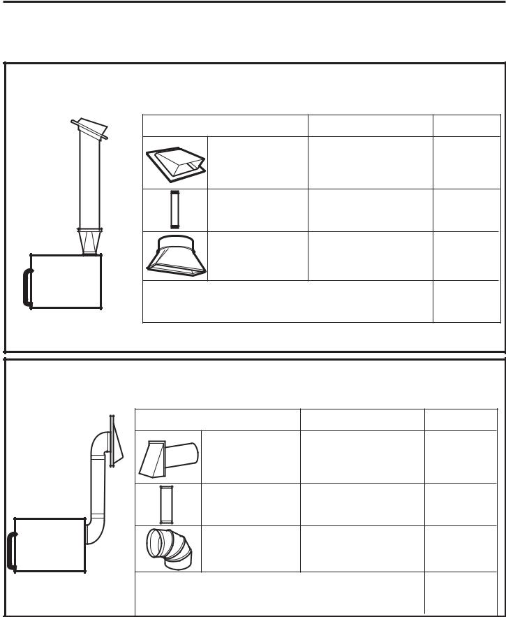
NOTE: 5HDG WKHVH QH[W WZR SDJHV RQO\ LI \RX SODQ WR YHQW \RXU H[KDXVW WR WKH RXWVLGH ,I \RX SODQ WR UHFLUFXODWH WKH DLU EDFN LQWR WKH URRP SURFHHG WR SDJH 6. %HORZ DUH H[DPSOHV RI 2XWVLGH 7RS ([KDXVW DQG 2XWVLGH %DFN ([KDXVW GXFW V\VWHP OD\RXWV 1RWH WKH SRVLWLRQ RI WKH PLFURZDYH RYHQ UHODWLYH WR WKH GXFW V\VWHP
2876,'( 723 (;+$867 (;$03/( 21/<
The following chart describes an example of one possible ductwork installation.
|
EQUIVALENT |
NUMBER |
|
EQUIVALENT |
|
DUCT PIECES |
LENGTH x |
USED |
= |
LENGTH |
|
Roof Cap |
24 Ft. |
x |
(1) |
= |
24 Ft. |
12 Ft. Straight Duct |
12 Ft. |
x |
(1) |
= |
12 Ft. |
(6s Round) |
|
|
|
|
|
Rectangular-to-Round |
5 Ft. |
x |
(1) |
= |
5 Ft. |
Transition Adaptor* |
|
|
|
|
|
Equivalent lengths of duct pieces are based on actual tests and
reflect requirements for good venting performance with any vent hood.
7RWDO /HQJWK )W
*IMPORTANT: If a rectangular-to-round transition adaptor is used, the bottom corners of the damper will have to be cut to fit, using the tin snips, in order to allow free movement of the damper.
2876,'( %$&. (;+$867 (;$03/( 21/<
The following chart describes an example of one possible ductwork installation.
|
EQUIVALENT |
NUMBER |
|
EQUIVALENT |
|
DUCT PIECES |
LENGTH* |
x |
USED |
= |
LENGTH |
Wall Cap |
40 Ft. |
x |
(1) |
= |
40 Ft. |
3 Ft. Straight Duct |
3 Ft. |
x |
(1) |
= |
3 Ft. |
(31ø4s x 10s Rectangular) |
|
|
|
|
|
90° Elbow |
10 Ft. |
x |
(2) |
= |
20 Ft. |
Equivalent lengths of duct pieces are based on actual tests and
reflect requirements for good venting performance with any vent hood.
7RWDO /HQJWK )W
NOTE: For back exhaust, care should be taken to align exhaust with space between studs, or wall should be prepared at the time it is constructed by leaving enough space between the wall studs to accommodate exhaust.
5
Installation Instructions
NOTE: If you need to install ducts, note that the total duct length of 31ø4s x 10s rectangular or 6s diameter round duct
VKRXOG QRW H[FHHG HTXLYDOHQW IHHW
Outside ventilation requires a HOOD EXHAUST DUCT. Read the following carefully:
NOTE: It is important that venting be installed using
the most direct route and with as few elbows as possible. This ensures clear venting of exhaust and helps prevent blockages. $OVR PDNH VXUH GDPSHUV VZLQJ IUHHO\ DQG
QRWKLQJ LV EORFNLQJ WKH GXFWV
Exhaust connection:
The hood exhaust has been designed to mate with a standard 31ø4s x 10s rectangular duct.
If a round duct is required, a rectangular-to-round transition adaptor must be used. Do not use less than a 6s diameter duct.
0D[LPXP GXFW OHQJWK
For satisfactory air movement, the total duct length of 31ø4s x 10s rectangular or 6s diameter round duct should
QRW H[FHHG HTXLYDOHQW IHHW
Elbows, transitions, wall and roof caps, etc., present additional resistance to airflow and are equivalent to a section of straight duct which is longer than their actual physical size. When calculating the total duct length, add the equivalent lengths of all transitions and adaptors plus the length of all straight duct sections. The chart below shows you how to calculate total equivalent ductwork length using the approximate feet of equivalent length of some typical duct pieces.
|
EQUIVALENT |
|
NUMBER |
|
EQUIVALENT |
DUCT PIECES |
LENGTH |
x |
USED |
= |
LENGTH |
|
|
|
|
|
|
Rectangular-to-Round |
5 Ft. |
x |
( |
) |
= |
|
|
Ft. |
|
|
|
|
|
|
Transition Adaptor* |
|
|
|
|
|
|
|
|
|
|
|
|
|
|
|
|
|
|
|
|
|
|
|
|
|
|
|
|
|
Wall Cap |
40 Ft. |
x |
( |
) |
= |
|
|
Ft. |
|
|
|
|
|
|
|
|
|||||||
|
|
|
|
|
|
|
|
|
|
|
|
|
|
|
|
|
|
|
|
|
|
|
|
|
|
|
|
|
|
|
|
|
|
|
|
90° Elbow |
10 Ft. |
x |
( |
) |
= |
|
|
Ft. |
|
|
|
|
|
|
|
|
|
|
|
|
|
|
|
|
|
|
|
|
|
45° Elbow |
5 Ft. |
x |
( |
) |
= |
|
|
Ft. |
|
|
|
|
|
|
|
|
|
|
|
|
|
|
|
|
|
|
|
|
|
90° Elbow |
25 Ft. |
x |
( |
) |
= |
|
|
Ft. |
|
|
|
|
|
|
|
|
|
|
|
|
|
|
|
|
|
|
|
|
|
45° Elbow |
5 Ft. |
x |
( |
) |
= |
|
|
Ft. |
|
|
|
|
|
|
|
|
|
|
|
|
|
|
|
|
|
|
|
|
|
Roof Cap |
24 Ft. |
x |
( |
) |
= |
|
|
Ft. |
|
|
|
|
|
|
|
|
|
|
|
|
|
|
|
|
|
|
|
|
|
Straight Duct 6s Round or |
1 Ft. |
x |
( |
) |
= |
|
|
Ft. |
|
|
|
|
|
|
|
|
|||||||
|
|
|
|
|
|
31ø4s x 10s Rectangular |
|
|
|
|
|
|
|
|
|
|
|
|
|
|
|
|
|
|
|
|
|
|
|
|
|
|
|
|
|
|
|
|
|
|
|
|
|
|
|
|
|
|
|
|
|
|
|
7RWDO 'XFWZRUN |
|
|
|
)W |
|
*IMPORTANT: If a rectangular-to-round transition adaptor is used, the bottom corners of the damper will have to be cut to fit, using the tin snips, in order to allow free movement of the damper.
Equivalent lengths of duct pieces are based on actual tests and reflect requirements for good venting performance with any vent hood.
6
Installation Instructions
'$0$*( ² 6+,30(17
INSTALLATION
,I WKH XQLW LV GDPDJHG LQ VKLSPHQW return the unit to the store in which it was bought for repair or replacement.
,I WKH XQLW LV GDPDJHG E\ WKH FXVWRPHU repair or replacement is the responsibility of the customer.
,I WKH XQLW LV GDPDJHG E\ WKH LQVWDOOHU (if other than the customer), repair or replacement must
be made by arrangement between customer and installer.
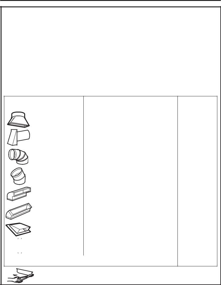
PARTS INCLUDED
HARDWARE PACKET
PART |
QUANTITY |
|
Wood Screws |
2 |
|
(3/16” x 2”) |
||
|
||
Toggle Bolts (and |
4 |
|
wing nuts) (1/4” x 3”) |
||
|
||
Self-aligning Machine |
|
|
Screw (1/4”-28 x |
3 |
|
3-1/4”) |
|
|
Nylon Grommet (for |
2 |
|
metal cabinets) |
||
|
||
Power Cord Strap |
1 |
|
(plastic) |
||
|
You will find the installation hardware contained in a packet with the unit. Check to make sure you have all these parts.
NOTE: Some extra parts are included.
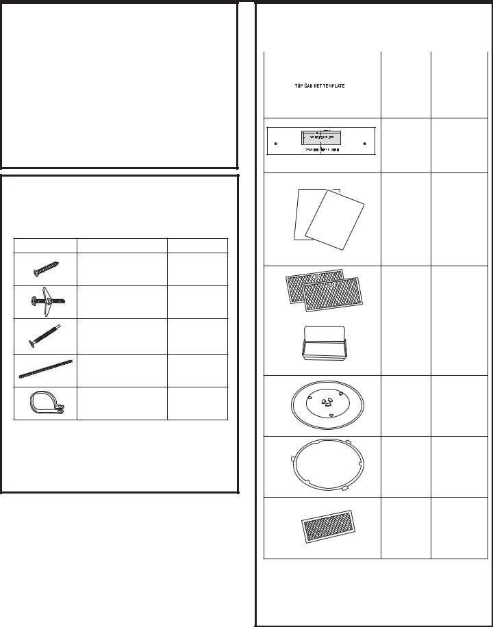
PARTS INCLUDED
ADDITIONAL PARTS
|
|
PART |
|
QUANTITY |
||
|
|
|
|
|
Top Cabinet |
1 |
|
|
|
|
|
||
|
|
|
|
|
||
|
|
|
|
|
||
|
|
|
|
|
Template |
|
|
|
|
|
|
||
|
|
|
|
|
|
|
|
|
|
|
|
|
|
|
|
|
|
|
|
|
|
≤ |
|
≤ |
Rear Wall |
|
|
Template |
1 |
|
|
INSTALLATION |
|
Installation |
|
INSTRUCTIONS |
|
|
|
OWNER |
|
Instructions |
1 |
MANUAL |
S |
||
|
|
|
|
|
|
and |
|
|
|
Owners |
1 |
|
|
Manual |
|
Grease |
2 |
|
Filters |
||
|
||
|
|
|
Exhaust |
1 |
|
Adaptor |
||
|
Tray 1
Turntable |
1 |
|
Ring |
||
|
Charcoal
Filter 1* (on some
models)
* NOTE:
)RU-90 DQG$90, filter is in accessory pack. It is not installed in the product.
)RU-10filter is already installed in the product. )RU 590 filter not included.
7
Installation Instructions
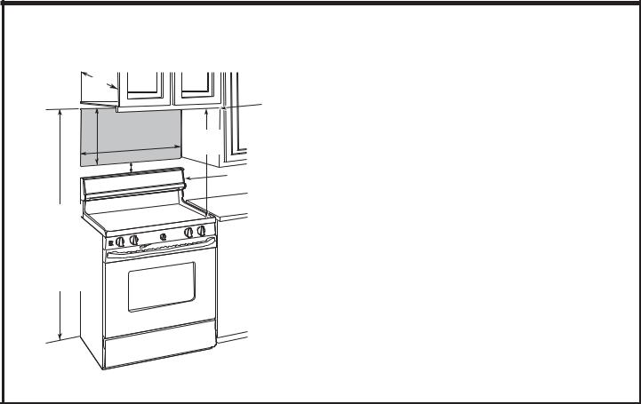
MOUNTING SPACE
12¾s max.
|
|
|
Bottom edge of |
|
|
|
cabinet needs to |
16-½s |
|
30s |
be 30s or more |
|
30s |
from the cooking |
|
|
min. |
surface |
|
|
|
||
|
2s |
|
Backsplash |
|
|
|
66s or more from the floor to the
top of the microwave oven
NOTES:
The space between the cabinets must be 30s wide and free of obstructions.
If the space between the cabinets is greater than 30s, a Filler Panel Kit may be used to fill in the gap between the microwave oven and the cabinets.
Your Owner’s Manual contains the kit number for your model.
This microwave oven is for installation over ranges up to 36s wide.
If you are going to vent your microwave oven to the outside, see Hood Exhaust Section for exhaust duct preparation.
When installing the microwave oven beneath smooth, flat cabinets, be careful to follow the instructions on the top cabinet template for power cord clearance.
0D[LPXP FDELQHW GHSWK DERYH DQG EHVLGH WKH XQLW is 12¾s.
)RU PRGHOV VHWXS LQ 5HFLUF ([KDXVW 'R QRW DOORZ cabinetry or other objects to block the airflow of the vent.
7KH SURGXFW VKRXOG QRW EH LQVWDOOHG RYHU DQ\ FRRNWRS or range with a combined BTU greater than 60,000 BTU.
8

Installation Instructions
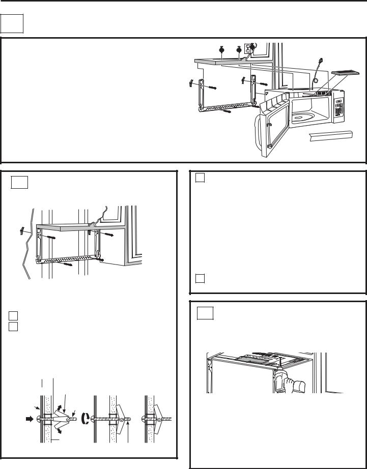
1 PLACEMENT OF THE MOUNTING PLATE
AREMOVING THE MICROWAVE
29(1 )520 7+( &$5721
REMOVING THE MOUNTING PLATE
1Open the box and fold back all four carton flaps fully against the carton sides. Remove the following items from the protective foam: installation instructions, filters, exhaust adaptor, damper, and the small hardware bag. Do not remove the foam protecting the front of the microwave oven.
Then carefully roll the microwave oven and carton
2over onto the top side. The microwave oven should be resting in the foam.
Carton
Foam
3Pull the carton up and off the microwave oven.
4The mounting plate is attached to the back of the microwave oven. Remove the two screws holding it to the microwave oven. The plate will be used as the rear wall template and for mounting the microwave oven to the wall.
5Set the microwave oven upright. Remove and properly discard plastic bags and foam.
6Open the microwave oven door and remove the plastic sheet and tape from inside the microwave oven door. Remove the tape covering the turntable hub.
B FINDING THE WALL STUDS
Wall
Studs
Center
1Find the studs, using one of the following methods: A. Stud finder.
OR
B.Use a hammer to tap lightly across the mounting surface to find a solid sound. This will indicate
a stud location.
2After locating the stud(s), find the center by probing the wall with a small nail to find the edges of the stud. Then place a mark halfway between the edges.
The center of any adjacent studs should be 16s or 24s from this mark.
3 Draw a line down the center of the studs.
IMPORTANT: The microwave must be connected to at least one wall stud.
9
Installation Instructions
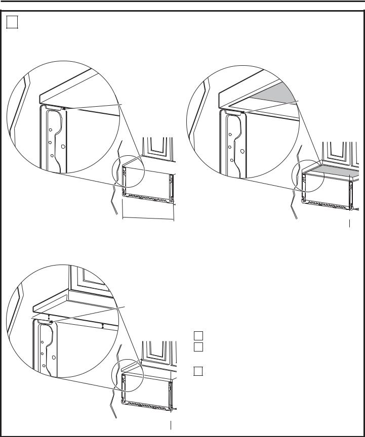
C DETERMINING MOUNTING PLATE LOCATION UNDER YOUR CABINET
Plate Position – flat bottom cabinet |
|
Plate Position – recessed cabinet bottom |
|
|
|
|
Mounting Plate |
Mounting Plate Tabs |
Tabs Touching the |
Back Frame of the |
|
Touching the Cabinet |
Cabinet |
Bottom |
|
30s to Cooktop
At least 30s, up to 36s
3ODWH 3RVLWLRQ ² FDELQHW ZLWK IURQW RYHUKDQJ
Mounting Plate with Tabs Below Cabinet Bottom the Same Distance as the Front Overhang Depth
Your cabinets may have decorative trim that interferes with the microwave oven installation. You may need to remove the decorative trim to install the microwave oven properly and to make it level.
THE MICROWAVE OVEN MUST BE LEVEL.
Use a level to make sure the cabinet bottom is level.
If the cabinets have a front overhang, install the mounting plate down the same distance as the front overhang depth. This will keep the microwave oven level.
1Measure the inside depth of the front overhang.
2Draw a horizontal line on the back wall an equal distance below the cabinet bottom as the inside depth
of the front overhang.
3 For this type of installation with front overhang, align the mounting tabs with this horizontal line, not touching the cabinet bottom as described in Step D.
30s to Cooktop
10
Installation Instructions
D ALIGNING THE MOUNTING PLATE
30”
Hole A
Hole C
Area E
 CAUTION:
:HDU JORYHV WR DYRLG FXWWLQJ ILQJHUV RQ VKDUS HGJHV
1Draw a vertical line on the wall at the center of the 30s wide space.
2Use the mounting plate as the template for the rear wall. Place the mounting plate on the wall, making sure that the tabs are WRXFKLQJ WKH ERWWRP RI WKH FDELQHW RU
WKH OHYHO OLQH GUDZQ LQ 6WHS & IRU FDELQHWV ZLWK IURQW RYHUKDQJ /LQH XS WKH QRWFK DQG FHQWHU OLQH RQ WKH PRXQWLQJ SODWH WR WKH FHQWHU OLQH RQ WKH ZDOO
3While holding the mounting plate with one hand, draw circles on the wall at holes A, B, C, and D (see illustration above/actual plate marked with arrows). Four holes
PXVW EH XVHG IRU PRXQWLQJ

 Hole B
Draw a Vertical Line on Wall from Center of Top Cabinet
 Hole D
Notch
NOTE: Holes C and D are inside area E. If neither C nor D is in a stud, find a stud somewhere in area E and draw a fifth circle to line up with the stud. It is important to use at least one wood screw mounted firmly in a stud
to support the weight of the microwave oven.
6HW WKH PRXQWLQJ SODWH DVLGH
 WARNING:5LVN RI HOHFWULF VKRFN &DQ FDXVH
LQMXU\ RU GHDWK 7DNH FDUH WR QRW GULOO LQWR HOHFWULFDO ZLULQJ inside walls or cabinets.
4Drill holes on the circles. If there is a stud, drill a 3ø16s hole for wood screws. For holes that don’t line up with a stud, drill a 5ø8s hole for toggle bolts.
NOTE: DO NOT MOUNT THE PLATE AT THIS TIME.
11

Installation Instructions
2 INSTALLATION TYPES &KRRVH $ % RU &
This microwave oven is designed for adaptation to the |
127( 6HOHFW WKH W\SH RI YHQWLODWLRQ UHTXLUHG IRU \RXU |
following 3 types of ventilation: |
installation and proceed to that section. |
$ 5HFLUFXODWLQJ 1RQ 9HQWHG 'XFWOHVV |
|
% 2XWVLGH 7RS ([KDXVW 9HUWLFDO 'XFW |
|
& 2XWVLGH %DFN ([KDXVW +RUL]RQWDO 'XFW |
|
A |
RECIRCULATING |
|
|
B |
OUTSIDE TOP EXHAUST |
|
|
|
121 9(17(' '8&7/(66 |
|
9(57,&$/ '8&7 |
|
|
||
|
|
|
|
|
Adaptor in Place for |
||
|
|
|
|
|
Outside Top Exhaust |
||
|
|
Convenience Cooking |
|
|
|
|
|
|
Express Cook |
|
|
Convenience Cooking |
|||
|
|
|
|
|
|||
|
1 |
2 |
3 |
|
|
|
|
|
4 |
5 |
6 |
|
|
|
|
|
7 |
8 |
9 |
|
Express Cook |
||
|
|
0 |
|
|
1 |
2 |
3 |
|
|
|
Start |
|
4 |
5 |
6 |
|
Cancel |
|
7 |
8 |
9 |
||
|
|
|
|
|
|||
|
|
|
|
|
|
0 |
|
|
|
|
|
|
Cancel |
Start |
|
6HH SDJH |
|
|
6HH SDJH |
|
|
||
A Charcoal Filter Accessory Kit is required for the non-vented |
|
|
|
|
|||
exhaust. (See your Owner’s Manual for the kit number.) |
|
|
|
|
|||
C |
OUTSIDE BACK EXHAUST |
|
|
|
+25,=217$/ '8&7 |
|
|
|
|
Convenience Cooking |
|
|
Express Cook |
||
|
1 |
2 |
3 |
|
4 |
5 |
6 |
|
7 |
8 |
9 |
|
|
0 |
|
|
Cancel |
Start |
|
6HH SDJH |
|
|
|
|
12 |
|
|
Installation Instructions
A RECIRCULATING 1RQ 9HQWHG 'XFWOHVV
INSTALLATION OVERVIEW
A1. Attach Mounting Plate to Wall
A2. Prepare Top Cabinet
A3. Adjust Blower Motor
A4. Install Charcoal Filter
A5. Mount the microwave oven
A6. Installing/Replacing the Charcoal Filter Without
Access to Top Screws and the Unit Has Already
Been Mounted.
A1 ATTACH THE MOUNTING PLATE TO THE WALL
Attach the plate to the wall using toggle bolts. At least one wood screw must be used to attach the plate to a wall stud.
1Remove the toggle wings from the bolts.
2Insert the bolts into the mounting plate through
the holes designated to go into drywall and reattach the toggle wings to 3ø4s onto each bolt.
7R XVH WRJJOH EROWV:
Spacing for Toggles More


 Than Wall Thickness
|
Toggle Wings |
|
Mounting |
Toggle |
|
Plate |
||
Bolt |
||
|
Wall |
Bolt End
13
3Place the mounting plate against the wall and insert the toggle wings into the holes in the wall to mount the plate.
NOTE: Before tightening toggle bolts and wood screw, make sure the tabs on the mounting plate touch the bottom of the cabinet or the horizontal level line when pushed flush against the wall and that the plate is properly centered under the cabinet.
 CAUTION: %H FDUHIXO WR DYRLG SLQFKLQJ
ILQJHUV EHWZHHQ WKH EDFN RI WKH PRXQWLQJ SODWH DQG the wall.
4Tighten all bolts. Pull the plate away from the wall to help tighten the bolts.
A2 USE TOP CABINET TEMPLATE
FOR PREPARATION OF TOP CABINET
You need to drill holes for the top support screws and a hole large enough for the power cord to fit through.
Read the instructions on the TOP CABINET TEMPLATE.
Tape it underneath the top cabinet.
Drill the holes, following the instructions on the TOP CABINET TEMPLATE.
 CAUTION: :HDU VDIHW\ JRJJOHV ZKHQ GULOOLQJ KROHV LQ WKH FDELQHW ERWWRP
Installation Instructions
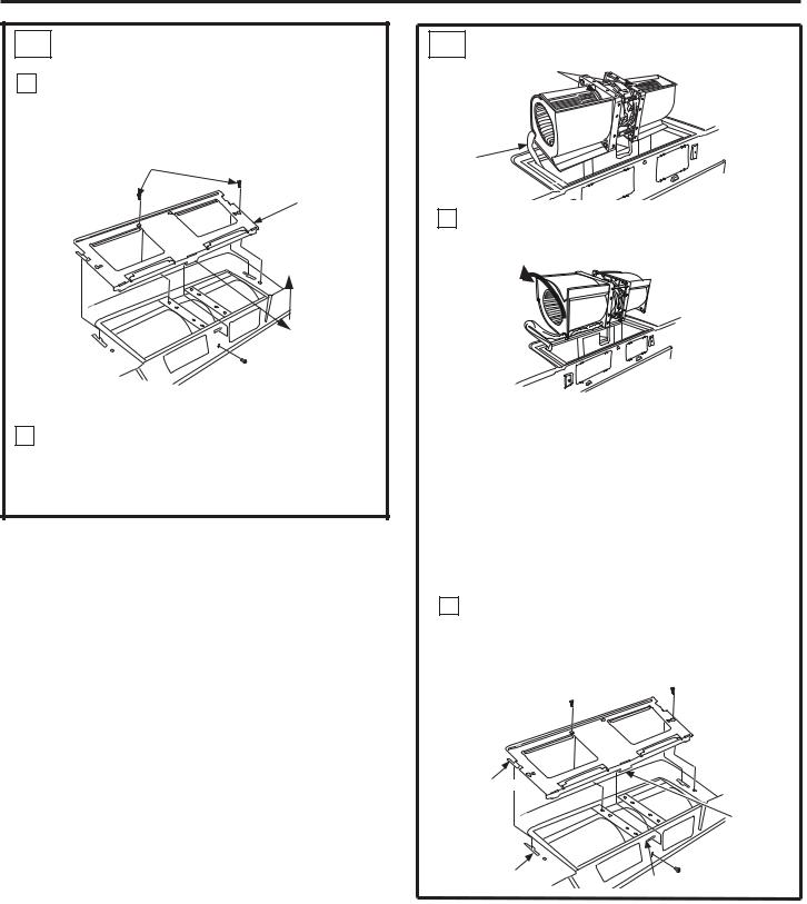
A3 ADJUST BLOWER MOTOR
1Remove the screws holding the blower unit and the screws securing the blower plate. Remove the blower plate from the outer case by sliding it toward the back of the microwave and pulling up.
Blower Motor Screws
Blower Plate
Blower

 Motor
Motor
Screw
2Carefully pull out the blower unit. The wires will extend far enough to allow you to adjust the blower unit.
A3 $'-867 %/2:(5 02725 FRQW
Fan Blades
Wires
Back of
Mircrowave
3Roll the blower so that fan blade openings are facing the top of the oven. Place the blower back into the opening.
Rotate 90°
Back of
Mircrowave
Note: Make sure the wires remain routed through the openings in the motor frame. To avoid damage to the fan motor wiring, insert motor carefully such that the fan motor wiring does not contact the microwave power cord bracket.
 WARNING: 5LVN RI (OHFWULF 6KRFN
Can cause injury or death. Do not pull or stretch the
EORZHU XQLW ZLULQJ 0DNH VXUH WKH ZLUHV DUH QRW pinched.
4Slide the blower plate back onto the microwave by placing the side tabs into the slots and pushing
gently until the back tab is seated into the rear slot. Replace 3 screws.
Side Tab
Rear Tab
Side Slot |
Rear Slot |
|
14
Installation Instructions
A4 INSTALLING THE CHARCOAL FILTER
1Remove 2 screws on top of microwave oven, just above the grille panel, using a Phillips screwdriver. If two screws are not accessible, see section A5.
2Open the door.
3Remove the grille.
Grille
Convenience Cooking
Express Cook
1 2 3
4 5 6
7 8 9
0
Cancel Start
4Insert the top of the filter up and into the grooves on both sides of the inside of the top opening. Once you have cleared the bottom tab, push the bottom of the filter in until it rests in place behind the tab.
Grooves in |
Filter (dashed to show |
|
Microwave for |
||
details of groves) |
||
Filter on Each Side |
||
|
Bottom Tab
5Replace the grille by inserting the top grill flange into the slots in the case as shown.
Grille


Grille
Ensure bottom tabs are seated as shown.
6Replace the 2 top screws.
7Close the door.
15
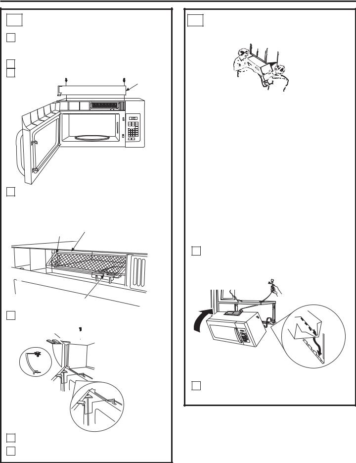
A5 MOUNT THE MICROWAVE OVEN
 CAUTION: 7R DYRLG WKH ULVN RI SHUVRQDO LQMXU\ EDFN LQMXU\ RU RWKHU LQMXULHV GXH WR H[FHVVLYH ZHLJKW RI WKH PLFURZDYH RU SURSHUW\ GDPDJH \RX ZLOO QHHG WZR SHRSOH WR LQVWDOO WKLV PLFURZDYH
IMPORTANT: Do not grip or use handle during installation.
 WARNING: 5LVN RI (OHFWULF 6KRFN &DQ FDXVH LQMXU\ RU GHDWK ,I LQVWDOOLQJ XQLW ZLWK PHWDO FRXQWHUWRSV FRYHU WKH HGJH RI WKH SRZHU VXSSO\ FRUG KROH ZLWK WKH SRZHU VXSSO\ FRUG EXVKLQJ
IMPORTANT: If filler blocks are not used, case damage may occur from overtightening screws.
NOTE: When mounting the microwave, thread power cord through hole in bottom of top cabinet. Keep it tight throughout Steps 1–3. Do not pinch cord or lift microwave oven by pulling cord.
1Lift microwave, tilt it forward, and hook slots at back bottom edge onto four lower tabs of mounting plate.
Power Cord 


2Rotate front of microwave oven up against cabinet bottom.

Installation Instructions
A5 MOUNT THE MICROWAVE OVEN
FRQW
3Insert 3 self-aligning screws (1ø4s-28 x 21ø4”) through outer top cabinet holes. Turn two full turns on each screw.
Cabinet Front
Cabinet Bottom Shelf
Filler Block
|
This distance |
|
Equivalent |
can NOT |
|
to Depth |
exceed 2” |
|
of Cabinet |
to ensure |
|
proper |
||
Recess |
||
installation |
||
|

 Self-Aligning Screw
Microwave Oven Top
Self-Aligning Screws
4Tighten the three screws to the top of the microwave oven. (While tightening screws, hold the microwave oven in place against the wall and the top cabinet.)
5Install grease filters. See the Owner’s Manual packed with the microwave oven.
16
A6 ,167$//,1* 5(3/$&,1* 7+(
CHARCOAL FILTER WITHOUT ACCESS TO TOP SCREWS AND THE UNIT HAS ALREADY BEEN MOUNTED
DISMOUNT THE MICROWAVE OVEN
 CAUTION: 7R DYRLG WKH ULVN RI SHUVRQDO LQMXU\ EDFN LQMXU\ RU RWKHU LQMXULHV GXH WR H[FHVVLYH ZHLJKW RI WKH PLFURZDYH RU SURSHUW\ GDPDJH \RX ZLOO QHHG WZR SHRSOH WR XQLQVWDOO WKLV PLFURZDYH
IMPORTANT: Do not grip or use handle during removal.
 WARNING: 5LVN RI (OHFWULF 6KRFN &DQ FDXVH LQMXU\ RU GHDWK ,I UHPRYLQJ XQLW ZLWK PHWDO FRXQWHUWRSV FRYHU WKH HGJH RI WKH SRZHU VXSSO\ FRUG KROH ZLWK WKH SRZHU VXSSO\ FRUG Q\ORQ JURPPHW
IMPORTANT: If filler blocks are not used, case damage may occur from overtightening screws.
1Loosen the 3 screws on the top of the microwave oven (inside the cabinet).
2Lift microwave, tilt it forward and unhook slots at back bottom edge from the four lower tabs of the mounting plate.
3Replace the filter using instructions from section A4.
4Reinstall unit following instructions from A5.
 Loading...