

Page 1

E-9722R Server
USERGUIDE
®
Page 2

Page 3

Contents
Chapter 1: Checking Out Your Gateway Server . . . . . . . . . . . . . . . . . . . . . . . 1
Front . . . . . . . . . . . . . . . . . . . . . . . . . . . . . . . . . . . . . . . . . . . . . . . . . . . . . . . . . . . . . . . . . . . . . 2
Control panel . . . . . . . . . . . . . . . . . . . . . . . . . . . . . . . . . . . . . . . . . . . . . . . . . . . . . . . 2
Back . . . . . . . . . . . . . . . . . . . . . . . . . . . . . . . . . . . . . . . . . . . . . . . . . . . . . . . . . . . . . . . . . . . . . . 3
Interior . . . . . . . . . . . . . . . . . . . . . . . . . . . . . . . . . . . . . . . . . . . . . . . . . . . . . . . . . . . . . . . . . . . 4
System board . . . . . . . . . . . . . . . . . . . . . . . . . . . . . . . . . . . . . . . . . . . . . . . . . . . . . . . . . . . . . 5
Connectors . . . . . . . . . . . . . . . . . . . . . . . . . . . . . . . . . . . . . . . . . . . . . . . . . . . . . . . . . 5
Hot-swap backplanes . . . . . . . . . . . . . . . . . . . . . . . . . . . . . . . . . . . . . . . . . . . . . . . . . . . . . . 7
SATA II/SAS backplane . . . . . . . . . . . . . . . . . . . . . . . . . . . . . . . . . . . . . . . . . . . . . . . 7
LED information . . . . . . . . . . . . . . . . . . . . . . . . . . . . . . . . . . . . . . . . . . . . . . . . . . . . . 8
Getting Help . . . . . . . . . . . . . . . . . . . . . . . . . . . . . . . . . . . . . . . . . . . . . . . . . . . . . . . . . . . . . . . 9
Server Companion DVD . . . . . . . . . . . . . . . . . . . . . . . . . . . . . . . . . . . . . . . . . . . . . . 9
Gateway Web site . . . . . . . . . . . . . . . . . . . . . . . . . . . . . . . . . . . . . . . . . . . . . . . . . . . 9
Telephone support . . . . . . . . . . . . . . . . . . . . . . . . . . . . . . . . . . . . . . . . . . . . . . . . . . 9
Chapter 2: Setting Up Your Server. . . . . . . . . . . . . . . . . . . . . . . . . . . . . . . . . 11
Setting up the hardware . . . . . . . . . . . . . . . . . . . . . . . . . . . . . . . . . . . . . . . . . . . . . . . . . . 12
Protecting from power source problems . . . . . . . . . . . . . . . . . . . . . . . . . . . . . . . . . . . . 12
Starting your server . . . . . . . . . . . . . . . . . . . . . . . . . . . . . . . . . . . . . . . . . . . . . . . . . . . . . . .13
Understanding the power-on self-test . . . . . . . . . . . . . . . . . . . . . . . . . . . . . . . .13
Turning off your server . . . . . . . . . . . . . . . . . . . . . . . . . . . . . . . . . . . . . . . . . . . . .14
Setting up the operating system . . . . . . . . . . . . . . . . . . . . . . . . . . . . . . . . . . . . . . . . . . . 14
Initial hardware settings . . . . . . . . . . . . . . . . . . . . . . . . . . . . . . . . . . . . . . . . . . . . . . . . . . .14
Chapter 3: Maintaining Your Server . . . . . . . . . . . . . . . . . . . . . . . . . . . . . . . 15
Caring for your server . . . . . . . . . . . . . . . . . . . . . . . . . . . . . . . . . . . . . . . . . . . . . . . . . . . . .16
Cleaning your server . . . . . . . . . . . . . . . . . . . . . . . . . . . . . . . . . . . . . . . . . . . . . . .16
Preparing for system recovery . . . . . . . . . . . . . . . . . . . . . . . . . . . . . . . . . . . . . . . . . . . . .17
Recording the BIOS configuration . . . . . . . . . . . . . . . . . . . . . . . . . . . . . . . . . . . . 17
System administration . . . . . . . . . . . . . . . . . . . . . . . . . . . . . . . . . . . . . . . . . . . . . . . . . . . .17
Gateway Systems Manager . . . . . . . . . . . . . . . . . . . . . . . . . . . . . . . . . . . . . . . . . 17
Server security . . . . . . . . . . . . . . . . . . . . . . . . . . . . . . . . . . . . . . . . . . . . . . . . . . . . . 18
Identifying your server . . . . . . . . . . . . . . . . . . . . . . . . . . . . . . . . . . . . . . . . . . . . . . . . . . . . 18
Updating the baseboa r d manageme n t controll er firmware . . . . . . . . . . . . . . . . . . .19
Using your Server Companion DVD . . . . . . . . . . . . . . . . . . . . . . . . . . . . . . . . . . . . . . . . . 19
Viewing documents . . . . . . . . . . . . . . . . . . . . . . . . . . . . . . . . . . . . . . . . . . . . . . . .19
Installing drivers and programs . . . . . . . . . . . . . . . . . . . . . . . . . . . . . . . . . . . . .20
Booting from the Server Companion DVD . . . . . . . . . . . . . . . . . . . . . . . . . . . . .21
Chapter 4: Installing Components. . . . . . . . . . . . . . . . . . . . . . . . . . . . . . . . . . 23
Preparing to install components . . . . . . . . . . . . . . . . . . . . . . . . . . . . . . . . . . . . . . . . . . . . 24
Selecting a place to work . . . . . . . . . . . . . . . . . . . . . . . . . . . . . . . . . . . . . . . . . . .24
Gathering the tools you need . . . . . . . . . . . . . . . . . . . . . . . . . . . . . . . . . . . . . . .24
Getting Help . . . . . . . . . . . . . . . . . . . . . . . . . . . . . . . . . . . . . . . . . . . . . . . . . . . . . . .24
Preventing static electricity discharge . . . . . . . . . . . . . . . . . . . . . . . . . . . . . . . . . . . . . . .24
Opening the server case . . . . . . . . . . . . . . . . . . . . . . . . . . . . . . . . . . . . . . . . . . . . . . . . . . .25
Closing the server case . . . . . . . . . . . . . . . . . . . . . . . . . . . . . . . . . . . . . . . . . . . . . . . . . . . . 27
i
Page 4

Contents
Installing and removing drives . . . . . . . . . . . . . . . . . . . . . . . . . . . . . . . . . . . . . . . . . . . . .28
Removing and installing an optical drive . . . . . . . . . . . . . . . . . . . . . . . . . . . . . .28
Removing and installing a hard drive . . . . . . . . . . . . . . . . . . . . . . . . . . . . . . . . .29
Filling empty drive bays . . . . . . . . . . . . . . . . . . . . . . . . . . . . . . . . . . . . . . . . . . . . .31
Installing memory . . . . . . . . . . . . . . . . . . . . . . . . . . . . . . . . . . . . . . . . . . . . . . . . . . . . . . . . .31
Installing and removing PCI expansion cards . . . . . . . . . . . . . . . . . . . . . . . . . . . . . . . . .34
Removing and installing the PCI rise r assembly, a riser, or a PCI card . . . .34
Replacing system fans . . . . . . . . . . . . . . . . . . . . . . . . . . . . . . . . . . . . . . . . . . . . . . . . . . . . .38
Replacing or adding a processor . . . . . . . . . . . . . . . . . . . . . . . . . . . . . . . . . . . . . . . . . . . .41
Replacing a power supply module . . . . . . . . . . . . . . . . . . . . . . . . . . . . . . . . . . . . . . . . . .43
Replacing the power distribution module . . . . . . . . . . . . . . . . . . . . . . . . . . . . . . . . . . . .44
Replacing the hot-swap backplane . . . . . . . . . . . . . . . . . . . . . . . . . . . . . . . . . . . . . . . . . .46
Installing and removing an optional mezzanine board . . . . . . . . . . . . . . . . . . . . . . . .47
Replacing the CMOS battery . . . . . . . . . . . . . . . . . . . . . . . . . . . . . . . . . . . . . . . . . . . . . . . .48
Replacing the control panel . . . . . . . . . . . . . . . . . . . . . . . . . . . . . . . . . . . . . . . . . . . . . . . .49
Replacing the system board . . . . . . . . . . . . . . . . . . . . . . . . . . . . . . . . . . . . . . . . . . . . . . . .49
Chapter 5: Using the BIOS Setup Utility . . . . . . . . . . . . . . . . . . . . . . . . . . . . .51
Opening the BIOS Setup utility . . . . . . . . . . . . . . . . . . . . . . . . . . . . . . . . . . . . . . . . . . . . . .52
Updating the BIOS . . . . . . . . . . . . . . . . . . . . . . . . . . . . . . . . . . . . . . . . . . . . . . . . . . . . . . . . .52
Recovering the BIOS . . . . . . . . . . . . . . . . . . . . . . . . . . . . . . . . . . . . . . . . . . . . . . . . . . . . . . .53
Resetting the BIOS . . . . . . . . . . . . . . . . . . . . . . . . . . . . . . . . . . . . . . . . . . . . . . . . . . . . . . . .54
Resetting BIOS passwords . . . . . . . . . . . . . . . . . . . . . . . . . . . . . . . . . . . . . . . . . . .55
Updating and recovering the BMC . . . . . . . . . . . . . . . . . . . . . . . . . . . . . . . . . . . . . . . . . .56
Updating the BMC firmware . . . . . . . . . . . . . . . . . . . . . . . . . . . . . . . . . . . . . . . . .56
Recovering the BMC . . . . . . . . . . . . . . . . . . . . . . . . . . . . . . . . . . . . . . . . . . . . . . . .56
Chapter 6: Troubleshooting . . . . . . . . . . . . . . . . . . . . . . . . . . . . . . . . . . . . . . .57
Telephone support . . . . . . . . . . . . . . . . . . . . . . . . . . . . . . . . . . . . . . . . . . . . . . . . . . . . . . . .58
Before calling Gateway Customer Care . . . . . . . . . . . . . . . . . . . . . . . . . . . . . . .58
Telephone support . . . . . . . . . . . . . . . . . . . . . . . . . . . . . . . . . . . . . . . . . . . . . . . . .58
Tutoring and training . . . . . . . . . . . . . . . . . . . . . . . . . . . . . . . . . . . . . . . . . . . . . . . . . . . . . .59
Safety guidelines . . . . . . . . . . . . . . . . . . . . . . . . . . . . . . . . . . . . . . . . . . . . . . . . . . . . . . . . . .59
Error messages . . . . . . . . . . . . . . . . . . . . . . . . . . . . . . . . . . . . . . . . . . . . . . . . . . . . . . . . . . .59
Troubleshooting . . . . . . . . . . . . . . . . . . . . . . . . . . . . . . . . . . . . . . . . . . . . . . . . . . . . . . . . . .63
First steps . . . . . . . . . . . . . . . . . . . . . . . . . . . . . . . . . . . . . . . . . . . . . . . . . . . . . . . . .63
Battery replacement . . . . . . . . . . . . . . . . . . . . . . . . . . . . . . . . . . . . . . . . . . . . . . . .63
Beep codes . . . . . . . . . . . . . . . . . . . . . . . . . . . . . . . . . . . . . . . . . . . . . . . . . . . . . . . .64
Diagnostic LEDs . . . . . . . . . . . . . . . . . . . . . . . . . . . . . . . . . . . . . . . . . . . . . . . . . . . .65
BIOS . . . . . . . . . . . . . . . . . . . . . . . . . . . . . . . . . . . . . . . . . . . . . . . . . . . . . . . . . . . . . . .70
Optical drive . . . . . . . . . . . . . . . . . . . . . . . . . . . . . . . . . . . . . . . . . . . . . . . . . . . . . . .70
Expansion cards . . . . . . . . . . . . . . . . . . . . . . . . . . . . . . . . . . . . . . . . . . . . . . . . . . . .71
Hard drive . . . . . . . . . . . . . . . . . . . . . . . . . . . . . . . . . . . . . . . . . . . . . . . . . . . . . . . . .71
Internet . . . . . . . . . . . . . . . . . . . . . . . . . . . . . . . . . . . . . . . . . . . . . . . . . . . . . . . . . . .72
Keyboard . . . . . . . . . . . . . . . . . . . . . . . . . . . . . . . . . . . . . . . . . . . . . . . . . . . . . . . . . .72
LED information . . . . . . . . . . . . . . . . . . . . . . . . . . . . . . . . . . . . . . . . . . . . . . . . . . . .72
Memory . . . . . . . . . . . . . . . . . . . . . . . . . . . . . . . . . . . . . . . . . . . . . . . . . . . . . . . . . . .72
ii
Page 5

www.gateway.com
Monitor . . . . . . . . . . . . . . . . . . . . . . . . . . . . . . . . . . . . . . . . . . . . . . . . . . . . . . . . . . .72
Power . . . . . . . . . . . . . . . . . . . . . . . . . . . . . . . . . . . . . . . . . . . . . . . . . . . . . . . . . . . . . 73
Processor . . . . . . . . . . . . . . . . . . . . . . . . . . . . . . . . . . . . . . . . . . . . . . . . . . . . . . . . . . 73
Appendix A: Server Specifications . . . . . . . . . . . . . . . . . . . . . . . . . . . . . . . . 75
System specifications . . . . . . . . . . . . . . . . . . . . . . . . . . . . . . . . . . . . . . . . . . . . . . . . . . . . .76
System board specifications . . . . . . . . . . . . . . . . . . . . . . . . . . . . . . . . . . . . . . . . . . . . . . . 76
Environmental specifications . . . . . . . . . . . . . . . . . . . . . . . . . . . . . . . . . . . . . . . . . . . . . . .77
Electronic specifications . . . . . . . . . . . . . . . . . . . . . . . . . . . . . . . . . . . . . . . . . . . . . . . . . . .77
Memory map . . . . . . . . . . . . . . . . . . . . . . . . . . . . . . . . . . . . . . . . . . . . . . . . . . . . . .77
Interrupts . . . . . . . . . . . . . . . . . . . . . . . . . . . . . . . . . . . . . . . . . . . . . . . . . . . . . . . . . 78
Connector pinouts . . . . . . . . . . . . . . . . . . . . . . . . . . . . . . . . . . . . . . . . . . . . . . . . . .78
Additional specifications . . . . . . . . . . . . . . . . . . . . . . . . . . . . . . . . . . . . . . . . . . . . . . . . . . . 81
Appendix B: BIOS Settings . . . . . . . . . . . . . . . . . . . . . . . . . . . . . . . . . . . . . . 83
Appendix C: Legal Information. . . . . . . . . . . . . . . . . . . . . . . . . . . . . . . . . . . 91
Appendix D: Legal Information . . . . . . . . . . . . . . . . . . . . . . . . . . . . . . . . . . 95
iii
Page 6

Contents
iv
Page 7

CHAPTER 1
Checking Out Y our Gat ewa y Server
• Front
• Back
• Back
• Interior
• System board
• Hot -sw ap bac kplane s
• Getting Help
1
Page 8

Front
CHAPTER 1: Checking Out Your Gateway Server
Hard drives (as many as 12)
Hard drive
tray LEDs
Optical drive
SMIL module
bay (optional) Control panel
Control panel
VGA po r t
USB port s (2 )
Power bu tton
ID bu tton
Powe r LE D
ID LED
NIC status
LED
System fault LED
Reset bu tton
NMI b utto n
2
Page 9
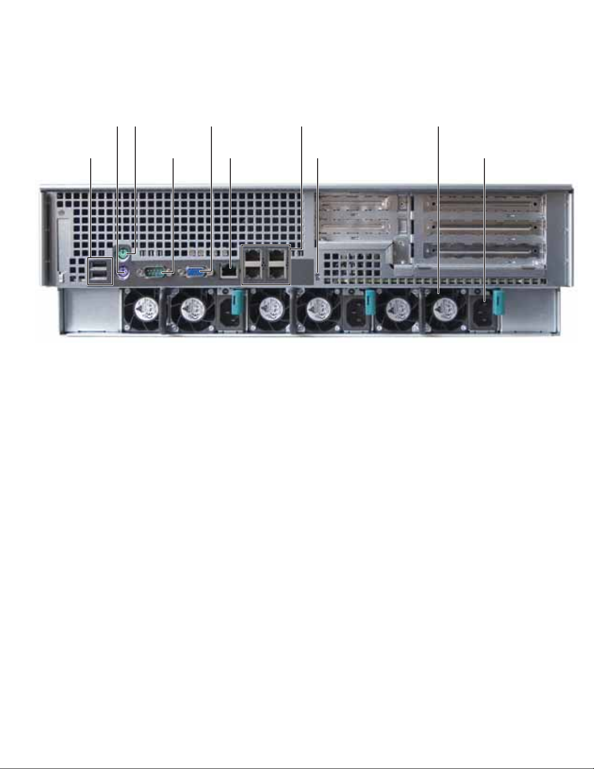
Back
www.gateway.com
PS/2 Keyboard
USB po rts (2)
port
PS/2 Mouse
port
Serial port
VGA p o rt
Server management
port
NIC ports (4)
ID LED
Power supply
AC power connector
3
Page 10

Interior
CHAPTER 1: Checking Out Your Gateway Server
1
2
3
4
5
6
7
8
9
10
# Feature # Feature
1 Syste m b o ard 6 Front panel
2 Fan duct 7 Front panel VGA connector
3 Syste m fa n s 8 SMIL module (optional)
4 SATA II/SAS backplane 9 Slimline DVD/CD-RW combo drive or
5 Hard drive bays 10 Riser card assem bly
DVD-RW drive
4
Page 11

S yst em board
Connectors
www.gateway.com
# Feature # Feature
1 PCI-X/PCI-E expansion slot (J41) 19 DIMM socket group for processor 0 (J24, J125,
2 PCI-E expansion slot (J35) 20 Processor 0 (CPU0) socket
3 DIMM socket group for processor 1 (J33, J32,
J31, J30)
4 ID LED (CR10) 22 IPMB connector (J43)
5 Dual NIC 2 and 3 connector (RJ-45) (J26) 23 SMIL connector (J37)
6 Dual NIC 0 and 1 connector (RJ-45) (J23) 24 Front panel connector (J45)
7 Server management port (RJ-45) (J21) 25 Front panel VGA connector (J46)
8VGA port (J17) 26I
21 IDE connector (J36)
J27, J28)
2
C (SMBus) signal connector (J44)
5
Page 12

CHAPTER 1: Checking Out Your Gateway Server
# Feature # Feature
9 Serial po rt (J12) 27 Main power connector (J48)
10 PS/2 keyboard and mouse ports (J10) 28 Internal USB port for USB floppy (J59)
11 Rear dual USB Port (J6) 29 Powe r s up ply I2C connector (J55)
12 DIMM socket group for processor 3 (J14, J15,
J16, J18)
13 Processor 3 (CPU3) socket 31 Floppy connector (J40)
14 P roc es sor 1 ( CP U1) so cket 32 Bat ter y ( B1)
15 Processor power connector (J1) 33 PCI-E mezzanine board connector (J38)
16 Fan ta ch co nnector (J 2) 34 PCI -X mez zanin e bo ard co nne ctor ( J49)
17 DIMM socket group for processor 2 (J5, J17, J8,
J9)
18 Processor 2 (CPU2) socket 36 Chassis intrusion connector (J58)
30 System configuration jumper (J56)
35 Front panel USB connector (J53)
6
Page 13

Hot -sw ap backplanes
SA T A II/SAS backplane
www.gateway.com
# Feature # Feature
1 SATA II/SAS hard drive connector 0 10 SATA II/SA S ha rd d rive c on ne ctor 9
2 SATA II/SAS hard drive connector 1 11 SATA II/SAS hard drive connector 10
3 SATA II/SAS hard drive connector 2 12 SATA II/ SAS ha rd d rive c on ne ctor 11
2
4 SATA II/SAS hard drive connector 3 13 I
5 SATA II/SAS hard drive connector 4 14 Backplane SATA II/SAS connector
6 SATA II/SAS hard drive connector 5 15 3rd party conn ector
7 SATA II/SAS hard drive connector 6 16 1X4 pin hard drive power connector
8 SATA II/SAS hard drive connector 7 17 2x3 pin hard drive power connector
9 SATA II/SAS hard drive connector 8
C (SMBus) signal connector
7
Page 14
LED inf ormation
See the following table for a description of this server’s LEDs and the information they provide:
LED Name Function Location Color Description
CHAPTER 1: Checking Out Your Gateway Server
ID Aid in server
System Fault Visible fault
Hard drive tray
LEDs
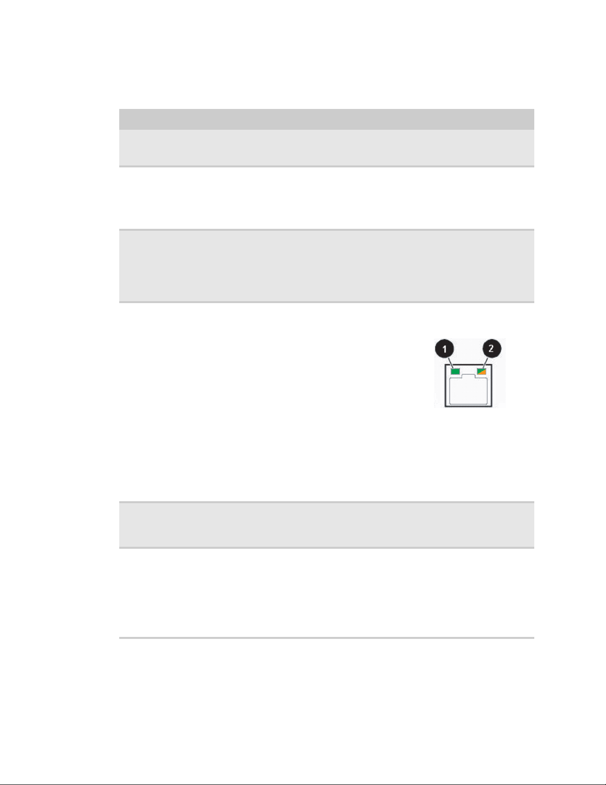
NIC status LEDs Identify NIC states Control panel and
identification
warning
Indicate drive
status and activity
Control panel and
back of system
board
Control panel Red Off = System normal
On each hard drive
tray
back I/O panel
RJ-45 connectors
Yellow
(front)
Blue (back)
Blue or red Blue (On) - Hard drive present
Blue (front)
Green/
Orange
(back)
On = Server identification
enabled
Blinking = Non-critical system
fault
On = Critic al system fault
(system ne eds to be shu t dow n
and serviced)
Blue (Blinking) - Hard drive
activity
Red (On) - Hard drive fault
Red (Blinking) - Hard drive
rebuilding
Off - No hard drive access
Blue (On) - Link
Blue (Blink) - Activity
Off - No link
LED 1 Green (On) - NIC linked
LED 1 Green (Blinking) - NIC
1 Gbps activity
LED 1 (Off) - No link
LED 2 Orange (On) Link speed
1Gbps
LED 2 Green (On) - Link at
100Mbps
LED 2 Green (Off) - Link at
10 Mbps
8
Power LE D Identify t he po wer
state of the system
AC power LED Identif y power
supply fault
Control panel Blue Off = Power is off
Power su pp ly
module
Green or
Orange
Blinking = Power saving state
(S1, S3, or S4)
On = Power is on
Green (On) - Pow er supply good
and receiving power
Orange (On) - Power supply
critical event causing shutdown
Orange (Blinking) - Close to
protection threshold or over
within 15 seconds
Off - Po we r suppl y not r ecei ving
power
Page 15

Get ting Help
In addition to your operating system’s documentation, you can use the following information
resources to help you use your server.
Server Companio n DVD
Use the Server Companion DVD to access file utilities, WindowsServer 2003 drivers, and
documentation for your server and its components. For instructions, see Using Your Serv er
Compa ni on DV D.
Gatew ay W eb site
Gateway provides a variety of information on its Web site to help you use your server.
Visit the Gateway Web site at support.gateway.com
• Technical documentation and product guides
• Technical tips and support
• Updated hardware drivers
• Order status
• Frequently asked questions (FAQs)
www.gateway.com
for :
T elephone sup port
You can access a wide range of services through your telephone, including customer service,
technical support, and information services. For more information, see “Telephone support” on
page 58.
9
Page 16

CHAPTER 1: Checking Out Your Gateway Server
10
Page 17

CHAPTER 2
Setting Up Your Serv er
• Setting up the hard war e
• Prot ecting f rom po wer sour ce problems
• Starting your serv er
• Setting up the operating sy stem
• Initial hardwar e set tings
11
Page 18

CHAPTER 2: Setting Up Your Server
Set ting up the hard war e
To make sure that your working environment is safe:
• Use a clean, dry, flat, stable surface for your server. Allow at least 6 inches at the back of
the server for cabling and air circulation.
• Use the instructions on your server’s setup poster to set up your hardware.
Caution
Your server comes with 3-wire ACpower cords fitted with the correct plug
style for your region. If this plug does not match the connector on your surge
protector, UP S, or wal l o u tle t, do no t attem pt to m od if y the pl ug i n any way. Use a
surge protector, UPS, or wall outlet that is appropriate for the supplied ACpower
cords.
• Use a grounded (three-prong) surge protector. A surge protector helps protect against AC
power fluctuations. For additional protection from power outages, we recommend that you
use an uninterruptible power supply (UPS).
• Avoid subjecting your server to extreme temperature changes. Do not expose your server
to direct sunlight, heating ducts, or other heat-generating objects. Damage caused by
extreme temperatures is not covered by your warranty. As a general rule, your server is
safest at temperatures that are comfortable for you.
• Keep your server and magnetic media away from equipment that generates magnetic
fields, such as unshielded stereo speakers. Strong magnetic fields can erase data on both
diskettes and hard drives. Even a telephone placed too close to the server may cause
interference.
Important
Keep the server boxes and packing material in case you need to ship the
server.
Prot ecting f rom pow er source pr oblems
Surge protectors, line conditioners, and uninterruptible power supplies can help protect your
server against power source problems.
Surge protectors
Caution
High voltages can enter your server through the power cord and the modem and
network connections. Protect your server by using a surge protector. If you have a modem,
use a surge protector that has the appropriate type of modem jack. During an electrical
storm, unplug the surge protector and the modem and network cables.
During a power surge, the voltage level of electricity coming into your server can increase to far
above normal levels and cause data loss or server damage. Protect your server and peripheral
devices b y c onnecting them t o a surge pr ot ec t or, which absorbs voltage surge s and prevents them
from reaching your server.
When you purchase a surge protector:
• Make sure that the surge protector meets the appropriate product safety certification for
your locati on, such as Und erwriters La boratories (UL) .
• Check the maximum amount of voltage the protector allows to pass through the line. The
lower the voltag e, the better the p rotection for your server.
• Check the energy absorption (dissipation) rating. The higher the energy absorption rating,
the better the p rotection for your server.
12
Line conditioners
A line conditioner protects your server from the small fluctuations in voltage from an electrical
supply. Most s erv ers can handle this var iation, called line noise, without problems. How ever, some
electrical sources include more line noise than normal. Line noise can also be a problem if your
server is located near, or shares a circuit with, a device that causes electromagnetic interference,
such as a television or a motor.
Page 19

Some surge protectors and uninterruptible power supplies include simple line-conditioning
capabilities.
Uninterruptible power supplies
Use an uninterruptible power supply (UPS) to protect your server from data loss during a total
power failure . A UPS us e s a batt ery to k eep y our server r unning temporar ily dur ing a power f ailur e
and lets you save your work and shut down your server. You cannot run your server for an
extended period of time while using only the UPS. To buy a UPS, visit www.gateway.com
Starting y our server
Before you start your server for the first time:
• Make sure that the server and monitor are plugged into a power outlet or surge protector
and that the surge protector (if you are using one) is turned on.
Caution
When you connect peripheral devices to the server, make sure that your
server and devices are turned off and the power cords are unplugged.
Important
At least two power supplies must be connected to AC power for the server
to function. All three power supplies must be connected to AC power for
redundancy.
www.gateway.com
.
• Make sure that al l ca bles are co nne cted securely to the co rrect port s a nd ja cks on the back
of the server.
To start the server:
1 Turn on any peripheral devices connected to the server.
2 Press the powe r b utto n (1) . Th e Powe r L ED (2 ) li gh ts.
If nothing happens when you press the power button:
• Make sure that the power cable(s) is plugged in securely and that your surge protector
(if you are using one) is plugged in and turned on.
• Make s ure tha t t he m on ito r i s co nn ecte d to the ser ver, pl ug ge d in to th e p owe r o utl et
or surge protec tor, and turned on. You may also need to adjust t he monitor’ s brightnes s
and contrast controls.
• If you cannot find the cause of the power loss, contact Gateway Customer Care. For
more informat ion, see “Gettin g Help” on pa ge 9 .
3 The first time you turn on the server, any pre-installed operating system may begin asking
you for configuration settings. See your operating system’s documentation for instructions
on configuring advanced settings for your specific network.
Understanding the po wer-on self -te st
When you turn on your server, the power-on self-test (POST) routine checks the server memory
and components. If POST finds any problems, the server displays error messages and issues
audible beeps. Write down any error messages that you see, then see “Error messa ges” on page59
and “Bee p codes” on page 64 for troubleshooting information.
13
Page 20

CHAPTER 2: Setting Up Your Server
T urning of f y our serv er
Every time you turn off your server, first shut down the operating system. You may lose data if
you do not follow the correct procedure.
To turn off the server:
Caution
The power button on the server does not turn off server ACpower. To
remove AC pow er from the se rve r, you m ust unp lu g the AC powe r c ord s fro m th e
wall outlet or power source. The power cords are considered the disconnect device
to th e m ai n ( AC ) po w e r.
1 Use the instructions in the operating system’s documentation or online help to shut down
the operating system. Whenev er pos sible , y ou should use the operating sy st em’s shut down
procedure instead of pressing the power button.
2 If your server did not turn off automatically, press the power button.
- OR Press the reset bu tton to re set t he ser ver.
Set ting up the operating s yst em
If you ordered your server with the operating system already installed by Gateway, in most cases
it is completely installed and the basic settings are already configured. The Windows Small
Business Server operating system may require additional installation, depending on the version
you ordered. See your operating system’s documentation for instructions on completing the
installation or configuring advanced settings for your specific network.
If you are installing an operating system because it was not already installed by Gateway, see
the appropriate installation guide for instructions.
Initial hard ware s ettings
Your server comes from the manufacturer with the correct initial hardware settings to operate
your server as configured. However, at some point you might want to change settings to reflect
a tasking change, a change in security requirements, or the addition of new resources to your
server.
You can change general hardware settings by using the BIOS Setup utility. For information on
the BIOS Setup utility, see “Using the BIOS Setup Utility” on page 51. For information on BIOS
settings, see “BIOS Settings” on page83.
14
Page 21

CHAPTER 3
Maintaining Y our Server
• Caring f or your s erver
• Preparing for s yst em recov ery
• Sy stem administration
• Identifying y our server
• Updating the baseboar d management controller
firmware
• Using your Server Companion DVD
15
Page 22

CHAPTER 3: Maintaining Your Server
Caring f or y our server
To extend the life of your server:
• Be careful not to bump or drop your server.
• When transporting your server, we recommend that you put it in the original packaging
materials.
• Keep your server and magnetic media away from equipment that generates magnetic
fields, such as unshielded speakers.
• Avoid subjecting your server to extreme temperatures. Do not expose your server to
heating ducts or other heat-generating objects. Damage caused by extreme temperatures
is not covered by your warranty. As a general rule, your server is safest at temperatures
that are comfortable for you.
• Keep al l l iqu id s away fro m yo ur s er ver. Whe n sp ill ed on to se rver co mp one nt s, a lm ost any
liquid can result in extremely expensive repairs that are not covered under your warranty.
• Avoid dusty or dirty work environments. Dust and dirt can clog the internal mechanisms
and can cause the server to overheat.
Cleaning y our serv er
Keeping your server clean and the vents free from dust helps keep your server performing at its
best. Your server cleaning kit could include:
• A soft, lint-free cloth
• Glass cleaner
• An aerosol can of air with a narrow, straw-like extension
• Isopropyl alcohol
• Cotton swabs
• A tape drive cleaning cartridge (if a tape drive is installed)
• A CD drive cleaning kit
Cleaning tips
Warning
When you shut down your server, the power turns off, but some electrical
current still flow s through your server. To avoid possible injury fro m elec t rical sh oc k,
unplug the power cords and all other cables connected to the server.
• Always turn off your server and other peripheral devices before cleaning any components.
• Use a damp, lint-free cloth to clean your server and other parts of your server system. Do
not use abrasive or solvent cleaners because they can damage the finish on components.
• Keep the cooling vents free of dust. With your server turned off and unplugged, brush the
dust away from the vents with a damp cloth, but be careful not to drip any water into the
vents.
Cleaning the k e yboard
You should clean the keyboard occasionally by using an aerosol can of air with a narrow,
straw-like extension to remove dust and lint trapped under the keys.
If you spill liquid on the keyboard, turn off your server and turn the keyboard upside down to
let the liquid drain. Let the keyboard dry completely before trying to use it again. If the keyboard
does not work after it dries, you may need to replaceit. Keyboard damage resulting from spilled
liquids is not covered by your warranty.
16
Page 23

www.gateway.com
Cleaning the scre en
Caution
The computer screen is made of specia lly coated glass and can be scratched or
damaged by abrasive or ammonia-based glass cleaners.
If your computer screen is an LCD display, use only a damp, soft cloth to clean it. Never spray
water d ire ctly on to the scree n.
- OR If your computer screen is not a flat panel display, use a soft cloth dampened with glass cleaner
to clean the screen. Never spray cleaner directly onto the screen.
Preparing f or s yst em reco very
If you have a diskette drive installed, you can create startup diskettes to help you recover. Startup
diskettes are diskettes that let you start the server and attempt to fix the problem. See your
operating system’s documentation or online help for instructions on creating startup diskettes.
If your system files become corrupted, you can use the diskettes you created to start your server.
If you have an optical drive, you can also create a bootable CD or DVD to help you recover. In
addition, you can also use a bootable Disk -on-ke y in any of the server’s USB ports. You r server’s
BIOS must be set up to poll the optical drive and USB ports for bootable files.
Some operating systems also l e t you crea te an emergency r e pa ir diskette, CD, DVD , or disk-on-key
to back up critical operating system files. See your operating system’s documentation or online
help for instructions on creating and using an emergency repair discs.
Recor ding the BIO S configur ation
To help keep track of your custom changes to BIOS settings and to prepare for system recovery,
you should record your BIOS configuration after you have your server set up and working. You
should also record your BIOS configuration whenever you upgrade or add new hardware to your
server.
To record your BIOS configuration:
1 Print the appendix for “BIOS Settings” on page83.
2 Restart your server, then press F2 at any time after you see the LEDs on your keyboard
flash or turn off. The BIOS Setup utility opens.
3 Record the BIOS settings on your printout.
S yst em administr ation
Gatew a y Sy stems Manager
Gateway Systems Manager (GSM) lets you manage multiple computers on a Windows network
from a single window, then implement commands and policies across the network with a single
action. With Gateway Systems Manager, you can run system management tasks which are
triggered by certain events or conditions.
For more informa tion, refer to the Gateway Baseboard Management Controller (BMC) User Guide
at support.gateway.com
information in the p rogram’s online help .
(by selecting this server from the list). You can also find additional
17
Page 24

Server sec urity
CHAPTER 3: Maintaining Your Server
Locking the server
To lock the server:
1 Remove the bez el lock k e y s f r om the inside of the bezel, t hen snap on the bezel. T he handles
must be installed for the bezel to snap on.
2 Insert the key into the lock and rotate it ¼ turn clockwise. To unlock it, rotate the key ¼
turn counter-clockwise.
Using BIOS secur ity passw ords
To prevent unauthorized use of the server, you can set server startup passwords. Set an
administrator password to prevent unauthorized access to the BIOS Setup utility.
To set the BIOS security passwords:
1 Restart your server, then press F2 at any time after you see the LEDs on your keyboard
flash or turn off. The BIOS Setup utility opens.
2 Select the Security menu.
3 Select Change Supervisor Password.
4 Type the password and press ENTER, then type it again and press ENTER.
5 Save your changes and close the BIOS Setup utility.
To remove a BIOS security password:
1 Restart your server, then press F2 at any time after you see the LEDs on your keyboard
flash or turn off. The BIOS Setup utility opens.
2 Select the Security menu, then select the password to remove.
3 Enter the curre nt password, then press E NTER.
Tip
Passwords can also be cleared using jumpers on the system board. For
instructions, see “Resetting BIOS passwords” on page55.
4 For the new password, leave the password field blank, then press ENTER. The p asswo rd i s
removed.
Identifying y our serv er
Important
If your server has an Intel IMM module installed, the system ID LED will turn on or
off when the System ID button is pressed. If no IMM Module is installed, the system ID LED
will blink when the System ID button is pressed.
While you are working on a cabinet that contains several slim servers, it can be difficult to keep
track of which server or servers you are currently working on. The System ID indicator is a yellow
LED (front) or blue LED (back) that you can turn on to help you locate the correct server. For the
System ID indicator to turn on, the server does not need to be turned on, but it does need to be
plugged in.
To turn on the System ID ind icator:
1 Press the ID button on the control panel of the server. The yellow (front) and blue (back)
ID LED indicators turn on. For the location of these LEDs, see “LED information” on page 8.
2 To turn off the in di cato r, press th e Syste m ID butto n.
18
Page 25

www.gateway.com
Updating the ba seboard man agement controller firmware
The baseboard management controller (BMC) performs several system management functions
such as:
• Monitoring server components (FRU) and sensor data records (SDR) (the information
provided depends on the option selected)
• Managing non-volatile storage for the system event log and sensor data records
• Interfacing with the emergency management port to send alerts and interact with remote
management systems
• Fault resilient booting (the extent depends on the option selected)
You should update the BMC firmware when Gateway Customer Care has instructed you to update
it.
To u p d at e t he B M C fi r m wa r e:
1 Down loa d th e B MC fir mware zip fi le from support.gateway.com.
2 Read the release notes for the firmware update.
3 Follow the instructions on the Web site or in the readme.txt file in the downloaded zip file
to update the firmware.
4 When th e BM C u pd ate i s c om pl ete, reb oo t yo ur s er ver.
Using y our Server C ompanion DVD
You can use your Server Compa nion D VD (SCDVD) to:
• Install hardware drivers
• Install programs
• View ser ver docu men tat ion
The Server Comp anio n D VD is a tool you can use to help maintain your server. The DVD contains:
• Computer and component documentation
• Drivers and utilities for servers running Windows 2003 Server
Vie wing doc uments
The DVD contains documents for your server and for some optional components. You can view
the documents with the Acrobat® Reader® version 4.0 and above.
To v i ew d o cu m e n ts :
1 Insert the SCDVD into the DVD drive on a computer running the Windows operating system.
The Gateway Application and Driver Recovery window ope ns.
- OR If the window does not open, run the file Runmenu.exe on the DVD.
2 Click Documentation. The server document list opens.
3 Click the title of the document you want to view. The document opens.
To access files manually, open the Docs\Manuals folder on the Server Compan ion DV D.
19
Page 26
CHAPTER 3: Maintaining Your Server
To i n s ta l l A c ro b a t R e ad e r 7:
• Click the link for Acrobat on the Documentation page.
- OR Run Docs\Reader\app21279\Setup.exe fro m t he Server Compa nion DVD.
Installing dri vers and pr ograms
Y o u can insta ll dr ivers and programs directly onto the server by using the Server Companion DVD.
You can also extract drivers onto diskette from the DVD at any Windows workstation.
Important
The SCDVD’s Gateway Application and Driver Recovery utility works only in Windows
operating systems.
To install drivers and programs at the server:
1 Insert the SCDVD into your server’s DVD drive. The Gateway Application and Driver Recovery
wind ow o pe ns.
- OR If the window does not open automatically, run the file Runmenu.exe on the DVD.
A list of programs and drivers that you can install appears in the Drivers and Application
Recovery li st.
2 Click the program or driver you want to install, then click Install. Follow any on-screen
instructions.
To access the files m anually, open the Drivers folder on the SCDVD, then open the appropriate
subfolder.
To extract drivers and programs to diskettes:
1 Insert the SCDVD into your server’s DVD drive. The Gateway Application and Driver Recovery
wind ow o pe ns.
- OR If the window does not open automatically, run the file Runmenu.exe on the DVD.
2 Click Extract Drivers.
3 Click your server model and server operating system at the right of the window, then click
Search. A list of programs and drivers with which you can create recovery disks (diskettes,
CDs, DVDs, or disk-on-keys) appears in the Drivers and Application Recovery list.
4 Click the program or driver you want to extract, then click Extract. Follow any on-screen
instructions.
To access the files m anually, open the Drivers folder on the SCDVD, then open the appropriate
subfolder.
20
Page 27

www.gateway.com
Booting fr om the Serv er C ompanion D VD
By booting from the SCDVD, you can repair applications and drivers or exit to the command
prompt.
Important
Although the SCDVD is bootable, it does not include network operating system files
and is not intended to restore your operating system.
To boot from the SCDVD:
1 With your server turned on, insert the SCDVD into the DVD drive.
2 Restart your server. A message appear s asking you to select an op tion.
3 Press any key to boot from the DVD. The Gateway Options Main Menu appears.
4 Follow any on-screen instructions.
You can use the options in this menu to reformat your hard drive, create mass-storage
driver disks, or reload selected applications.
21
Page 28

CHAPTER 3: Maintaining Your Server
22
Page 29

CHAPTER 4
Installing Components
• Preparing to install components
• Prev enting static electric ity discharge
• Opening the server case
• Closing the server case
• Installing and remov ing driv es
• Installing memory
• Installing and remov ing PCI e xpansion cards
• Replacing system fans
• Replacing or adding a p roces sor
• Replacing a po wer supply module
• Replacing t he pow er distribution module
• Replacing t he hot-s wap bac kplane
• Replacing the CMOS battery
• Replacing t he control panel
• Replac ing t he s yst em boar d
23
Page 30

CHAPTER 4: Installing Components
Preparing t o install components
Selecting a place to work
Work on your server in an area that:
• Is clean (avoid dusty areas).
• Is a low-static environment (avoid carpeted areas).
• Has a stable surface on which to set your server.
• Has enough room to place all of your server parts.
• Is near a grounded outlet so you can test your server after installation.
• Is near a telephone (in case you need help from Gateway Customer Care). The telephone
must be directly connected to a telephone jack and cannot be connected to your server.
Gathering t he tools y ou need
Tip
Blue latches, thumbscrews, or connectors indicate tool-less components.
Green latches and connectors indicate hot-swappable components.
Some tools and supplies that you may need to work on your server are:
• A note bo ok to t ake n otes
• A Phillips screwdriver
• A small flat-blade screwdriver
• Small containers to store various types of screws
• A grounding wrist strap (available at most electronic stores)
Getting Help
If you hav e questions about perf or ming an y of the s e procedure s, contac t Gat ewa y Customer Care .
For m ore in form ati on , se e “Getting Help” on page 9.
Pre v enting static electric ity dischar ge
Warning
To avoid exposure to dangerous electrical voltages and moving parts, turn off your
server and unplug the power cords and modem cable before opening the server case.
The components inside your server are extremely sensitive to static electricity, also known as
electrosta tic di scharge (ESD) .
Caution
ESD can permanently damage electrostatic discharge-sensitive components in the
server. Prevent ESD damage by following ESD guidelines every time you open the server
case.
Before working with server components, follow these guidelines:
• Turn off the server, then unplug the power cords and all other cables.
Important
If you are replacing a hot-swappable system fan, you do not need to turn
off the server or unplug the power cord(s) and other cables.
• Press the power button to drain any residual power from the server.
• Wear a grounding wrist strap (available at most electronics stores) and attach it to a bare
metal part of the server. You can also touch a bare metal surface on the back of the server
with your fing er.
24
Page 31

www.gateway.com
• Avoid static-causing surfaces such as carpeted floors, plastic, and packing foam.
• Avoid working on the server when your work area is extremely humid.
• Remove components from their antistatic bags only when you are ready to use them. Do
not lay components on the outside of antistatic bags because only the inside of the bags
provide electrostatic protection.
• Always hold expansion cards by their edges or their metal mounting brackets. Avoid
touching the edge connectors and components on the cards. Never slide expansion cards
or components over any surface.
Warning
To prevent risk of electric shock, do not insert any object into the vent holes
of the power supply.
Opening the serv er case
Warning
This server may have two power cords. To disconnect internal ACpower, you must
unplug both power cords.
Because the components inside your server are extremely sensitive to static electricity, make sure
that you follow the instructions at the beginning of this chapter to avoid static electricity damage.
To open the server:
Warning
Screws are required to support the front of the server when using the
standard cabin et ra ils. You must support the se rver while re moving the front screws
and while sliding the server off the cabinet rails. If the server is not supported,
damage to the server or injury may result.
1 Follow the instructions in “Preventing static electricity discharge” on page 24. Make sure
that you turn off the server, then unplug the power cord(s) and all other cables connected
to the server.
Important
If you are replacing a hot-swappable system fan, you do not need to turn
off the server or unplug the power cord(s) and other cables.
2 If the bezel is installed, unlock it, then pull it off.
3 If the server is mounted in a cabinet, remove it from the cabinet.
4 Place the server on a stable, non-skid surface.
25
Page 32

CHAPTER 4: Installing Components
5 Remove the sc r e w (1) at the f ront of the t op co v er, then press and hold the release button (2).
Caution
For correct cooling and air flow, always reinstall the top covers before you
turn on the server. Operating the server without the covers in place will cause the
server to overheat.
Important
The hard drive carriers shown in these illustrations may look different than
the actual hard drive carriers in your server.
6 Slide the top cover (3) toward the back of the case, then lift it off the case.
7 Move the fixed tabs (right and left) toward the middle of the server, then slide the front
top c over (2 ) towar d th e b ack of the ser ver an d l ift it o ff.
26
Page 33

www.gateway.com
Closing the server case
To close the server ca se:
1 Make sure that all of the internal cables are arranged inside the case so they will not be
pinched when you close the case.
2 Plac e th e fr ont top cove r o n th e s er ver, th en sli de it forw ard unt il it cli cks in to p la ce.
Important
The hard drive carriers shown in these illustrations may look different than
the actual hard drive carriers in your server.
3 Place the back top cover on the server, then slide it forward (1) until it clicks into place.
Replace the screw (2) to hold the top cover in place.
4 Reconnect the power cords and all other cables.
27
Page 34

CHAPTER 4: Installing Components
Installing and remo ving dri ve s
Your server’s basic configuration includes one optical drive and as many as twelve SAS/SATA
hot-swap hard drives.
As you prepare to install drives, remember:
• Before you install a drive, see the drive’s documentation for information on configuring the
drive, setting drive jumpers, and attaching cables.
• You may need to configure the drives you install using the BIOS Setup utility. Restart your
server, then press F2 at any time after you see the LEDs on your keyboard flash or turn off.
Remo ving and installing an optical dr ive
Caution
The optical drive is not hot-swappable. Before installing or removing the drive, make
sure that power is turned off and the power cord(s) is unplugged.
To remove and install an optical drive:
Important
The hard drive carriers shown in these illustrations may look different than
the actual hard drive carriers in your server.
1 Follow the instructions in “Preventing static electricity discharge” on page 24. Make sure
that you turn off the server, then unplug the power cord(s) and all other cables connected
to the server.
2 Unlock the bezel (if necessary) and remove it by pulling it from the chassis.
3 Follow the instructions in “Opening the server case” on page25.
4 Disconnect the 44-pin optical drive cable from the optical drive interface board.
5 Loosen the thumbscrew (1), then move the retaining clip (2) away from the optical drive.
28
Page 35

www.gateway.com
6 Move the optical drive to the right (3), then push the optical drive (4) out of the b ay.
7 Unscrew the two screws (5) that secur e t he optical drive interface board to t he optical driv e,
then remove the interface board.
8 Using the two screws you just removed, attach the optical drive interface board to the back
of the new optical drive.
9 Insert the optical drive into the optical drive bay, aligning it with the clips on the right and
left sides.
10 Secure the assembly by tightening the thumbscrew you previously loosened.
11 Attach the 44-pin optical drive cable to the back of the interface board.
12 Follow the instructions in “Closing the server case” on page 27.
13 Reinstall the bezel, if required, by snapping it into place on the front of the chassis.
14 Reconnect all power cords and peripheral device cables, then turn on the server.
Remo ving and in stalling a hard driv e
Important
Gateway tests and verifies the operation and compatibility of the drives it sells.
Especially in a hot-swap or mission-critical environment, additional or replacement drives
must conform to Gateway standards.
Use this procedure t o add or replace a hard dri v e in a hot - swap bay . Your server supports as many
as twelve 1-inch high, 3.5-inch hot-swap SATA and SATA II hard drives or twelve 1-inch high,
3.5-inch hot-swap SAS hard drives. You can purchase additional drives through your Gateway
Sales or Customer Care representative.
29
Page 36

CHAPTER 4: Installing Components
To remove and install a hot-swap hard drive:
Caution
Before you remove a failed drive, use the appropriate software and utilities
installed on the server to stop all activity on the failed drive. Instructions for using
the software are provided by the software manufacturer. Failure to do so may
dest roy the da ta on the dr ive.
1 Unlock the bezel (if necessary) and remove it by pulling it from the chassis.
2 Pull the drive release lever out. The drive release lever opens.
3 Pull the drive carrier straight out of the server.
4 Remove the four screws that secure the old hard drive (if you are replacing a drive), or the
dummy hard drive (if you are adding a drive), to the drive tray, then remove the drive (or
dummy drive) from the tray.
5 Using the four screws you removed, install the new hard drive into the drive tray.
6 Make sure that the tray’s release lever is open, then slide the new drive fully into the empty
hot-swap drive bay.
7 Push the lever back into place to secure the hard drive in the bay.
8 Reinstall the bezel, if required, by snapping it into place on the front of the chassis.
30
Page 37

Filling empty dr iv e bay s
Empty drive bays in the server must be filled by drive trays with either hard drives or dummy
hard drive s installed. With t he bez el remov ed, install the appro priat e carrier, then replace the bezel
by snapping it into place on the front of the server. E mpty drive carriers for unused drive bays
are included with your server.
Installing memory
Caution
Use only DDR2-667 MHz compliant, 184-pin, SDRAM registered ECC, DIMM memory
modules.
The system board supports 16 DDR2 667 MHz vertical DIMMs to provide up to 64 GB of memory
with ECC support. The 667 MHz differential memory clocks are driven by the AMD processor with
length matching and impedance controlled through all the DIMM slots. Supported DIMM sizes
include 256MB, 512MB, 1GB, 2GB, and 4GB.
The BIOS configures the memory controller to run in single channel, dual chann el, or four channel
mode.
Caution
When using dual rank (double row) DIMMs, a maximum of four loads per memory
channel is supported. This means a maximum of four dual rank DIMMs can be populated
on this system board.
www.gateway.com
DIMM banks must be populated using the following guidelines:
There are four groups of DIMMs with four DIMMs in each group on the system board, to support
processor 0, processor 1, processor 2, and processor 3. Each group supports one processor
(circled). When you insert the DIMM(s), you must always start with DIMMA1 and DIMMB1 as a pair.
Caution
All DIMMs installed must be the same speed. Do not install more than four dual rank
DIMMs or the BIOS will generate a memory configuration error.
31
Page 38

CHAPTER 4: Installing Components
If you insta ll two proc essors, refer to the following table :
DIMM Processor DIMMA0 DIMMB0 DIMMA1 DIMMB1 Tot a l M e m or y
4 Processor 0 - - 512 M B 512 M B 2 GB
Pr o c e ss o r 1 - - 512 M B 512 MB
Processor 0 - - 1 GB 1 GB 4 GB
Processor 1 - - 1 GB 1 GB
Processor 0 - - 2 GB 2 GB 8 GB
Processor 1 - - 2 GB 2 GB
Processor 0 - - 4 GB 4 GB 16 G B
Processor 1 - - 4 GB 4 GB
8 Processor 0 512 M B 512 M B 512 M B 512 M B 4 GB
Pr o c e ss o r 1 512 M B 512 M B 512 M B 512 M B
Processor 0 1 GB 1 GB 1 GB 1 GB 8 GB
Processor 1 1 GB 1 GB 1 GB 1 GB
Processor 0 2 GB 2 GB 2 GB 2 GB 16 GB
Processor 1 2 GB 2 GB 2 GB 2 GB
Processor 0 4 GB 4 GB 4 GB 4 GB 32 GB
Processor 1 4 GB 4 GB 4 GB 4 GB
32
Page 39

www.gateway.com
If you install four processors, refer to the following table:
DIMM Processor DIMMA0 DIMMB0 DIMMA1 DIMMB1 Tot a l M e m or y
8 Processor 0 - - 512 M B 512 M B 4 GB
Pr o c e ss o r 1 - - 512 M B 512 MB
Processor 2 - - 512 M B 512 M B
Pr o c e ss o r 3 - - 512 M B 512 MB
Processor 0 - - 1 GB 1 GB 8 GB
Processor 1 - - 1 GB 1 GB
Processor 2 - - 1 GB 1 GB
Processor 3 - - 1 GB 1 GB
Processor 0 - - 2 GB 2 GB 16 G B
Processor 1 - - 2 GB 2 GB
Processor 2 - - 2 GB 2 GB
Processor 3 - - 2 GB 2 GB
Processor 0 - - 4 GB 4 GB 32 GB
Processor 1 - - 4 GB 4 GB
Processor 2 - - 4 GB 4 GB
Processor 3 - - 4 GB 4 GB
16 Processor 0 512 M B 512 M B 512 M B 512 M B 8 GB
Pr o c e ss o r 1 512 M B 512 M B 512 M B 512 M B
Processor 2 512 M B 512 M B 512 M B 512 M B
Pr o c e ss o r 3 512 M B 512 M B 512 M B 512 M B
Processor 0 1 GB 1 GB 1 GB 1 GB 16 GB
Processor 1 1 GB 1 GB 1 GB 1 GB
Processor 2 1 GB 1 GB 1 GB 1 GB
Processor 3 1 GB 1 GB 1 GB 1 GB
Processor 0 2 GB 2 GB 2 GB 2 GB 32 GB
Processor 1 2 GB 2 GB 2 GB 2 GB
Processor 2 2 GB 2 GB 2 GB 2 GB
Processor 3 2 GB 2 GB 2 GB 2 GB
Processor 0 4 GB 4 GB 4 GB 4 GB 64 GB
Processor 1 4 GB 4 GB 4 GB 4 GB
Processor 2 4 GB 4 GB 4 GB 4 GB
Processor 3 4 GB 4 GB 4 GB 4 GB
33
Page 40

CHAPTER 4: Installing Components
To install or replace memory:
1 Follow the instructions in “Preventing static electricity discharge” on page 24. Make sure
that you turn off the server, then unplug the power cord(s) and all other cables connected
to the server.
2 Follow the instructions in “Opening the server case” on page25.
3 Pull the plastic tabs ( 1) away from the sides of the memory module slot. If you are replacing
a memory module, lift the old memory module (2) out of the slot.
4 Align the notch on the new module with the notch in the memory module slot and press
the module firmly into the slot. The tabs on the sides of the memory slot should secure the
memory module automatically.
5 Follow the instructions in “Closing the server case” on p age 27.
6 Turn on the server and open the BIOS setup utility. Verify the System Memo ry listed in
the Main menu. When you exit the BIOS setup utility, make sure that the operating system
completely loads. If you receive an error, review the memory overview information in
“Installing memory” on page 31.
Installing and remo ving PCI e xpansion cards
Caution
Always operate your server with the PCI riser assembly in place. The PCI riser
assembly is important for correct airflow within the server. Operating the server without
the PCI riser assembly in place could result in overheating and possible data loss or
equipment damage.
The system board provides one 280-pin PCI-X 66MHz expansion slot and one PCI-E x8 expansion
slot. One PCI-X 66 MHz expa nsion slot can support t wo PCI-E x8 expan sion slots with x8 speed
and one PCI-X 66 MHz using the riser card. One PCI-E expansion slot can support two PCI-E x8
expansion slots with x8 speed using the riser card. The riser card comes with the system package.
The edge connectors of the riser card connect to the PCI slots on the system board.
Remo ving and in stalling the P CI riser a ssembl y , a ri ser, or a PCI card
Caution
The PCI riser assembly and individual PCI expansion cards are not hot-swappable.
Before installing or removing any part of the assembly, make sure that power is turned off
and the power cord(s) is unplugged.
To remove and reinstall the PCI riser assembly, a riser, or a PCI card:
1 Follow the instructions in “Preventing static electricity discharge” on page 24. Make sure
that you turn off the server, then unplug the power cord(s) and all other cables connected
to the server.
2 Follow the instructions in “Opening the server case” on page25.
34
Page 41

www.gateway.com
3 If you are replacing a card, disconnect any cables that are attached to the old card.
4 Push the riser card locking tabs (1) in the directions shown in the illustration.
5 Lift the riser card assembly out of the chassis (2) and place it on a clean, static-free surface.
35
Page 42

CHAPTER 4: Installing Components
6 Press down and open the release lever (4) and flip open the card guide tab (5).
7 Remove the expansion card (6). If you are not replacing the card, install a slot cover (7) on
the back of the ri ser card assembly.
Caution
Do not touc h the c ontact s on t he bottom part of the expansion card. Touching
the contacts can cause electrostatic damage to the card.
36
8 If you are replacing the riser card, continue with the next step.
- OR If you are replacing the PCI card, go to Step11.
Page 43

www.gateway.com
9 Press the tab (8 ) hold ing the rise r card in the riser card assembly, then push the riser c ard
in the direction shown (9) to unlock and remove it from the standoffs.
Standoff
10 Inse rt the new riser card i nto the riser card assemb ly, then push it toward the b ack of the
assembly. It should snap into place.
11 Insert the new PCI card into the riser card, making sure any connectors extend through the
slot at the back of the assembly and that the card is fully seated in the riser card.
12 Close the release lever (see Step6) and the card guide tab.
13 Positio n the PC I riser c ard assembly (1) over the PCI socket on the ser ver boa rd, the n press
the PCI riser card assembly into the PCI socket until it clicks i nto place.
14 Follow the instructions in “Closing the server case” on page 27.
15 See the card’s documentation for software installation instructions.
37
Page 44

CHAPTER 4: Installing Components
Re placing sy stem f ans
This server contains five system fan groups seated in the fan cage. The fan cage is located inside
the chassis and can hold as many as five groups of hot-swappable fans. When replacing a fan, it
is not necessary to power off the server. These fans maintain the ideal temperature for the system
board, backplane and disk drives. If one fan group fails, the speed of the other fan groups will
increase. With the bad one replaced, the other fan groups may revert to the normal speed.
To replace a system fan:
1 Follow the instructions in “Preventing static electricity discharge” on page 24.
2 Follow the instructions in “Opening the server case” on page25, but do not turn off the
server.
3 Remove the fan duct..
4 Determine which fan group needs to be replaced by noting which fans are not operating.
5 Pull up the lo cki ng han dl e (1) o n th e sys tem fan , th en lift the fan gro up (2) fr om t he fan
cage in the chassis.
38
6 Insert the replacement fan group into the fan cage and press down the locking handle to
secure the fan group in place.
Important
Make su re th at the ar rows on top of the fan s i nd ica ti ng ai rf lo w p oin t to th e
back of the chassis. The fan cable should exit the fan module toward the back of
the chass is .
7 Replace the fan duct by placing it in the chassis.
8 Follow the instructions in “Closing the server case” on p age 27.
Page 45

www.gateway.com
To replace the system fans and the fan cage:
1 Follow the instructions in “Preventing static electricity discharge” on page 24.
2 Follow the instructions in “Opening the server case” on page25.
3 Remove the fan duct by lifting it ou t of the chassis.
4 Lift the retaining clip (1).
39
Page 46

CHAPTER 4: Installing Components
5 Lift one side of the fan cage (2) and disengage the retention tab (3), then disconnect the
fan power and fan tach cables from the system board and remove the fan cage from the
chassis.
6 Inse rt the fan s i nto t he new fan c ag e.
Important
Make su re th at the ar rows on top of the fan s i nd ica ti ng ai rf lo w p oin t to th e
back o f th e ch assi s.
7 Connect the fan power and fan tach cables to the system board, then insert the retention
tab (1) into the corresponding clip on the chassis and push the other side of the fan cage
down (2), making sure that the retaining clip is inserted into the hole in the chassis.
8 Replace the fan duct by placing it into the chassis.
9 Follow the instructions in “Closing the server case” on p age 27.
40
Page 47

www.gateway.com
Re placing or adding a proce ssor
Warning
Processors and heat sinks may be hot if the computer has been running. Before
replacing a processor or heat sink, let them cool for several minutes.
Caution
A heat sink must be installed on the processor. Installing a processor without a heat
sink could damage the processor.
The system board supports as many a s four AMD® Optero n ™ 80 00 serie s processors with 3.0 GHz
Hyper Transport Bus. With four 12 07-pin LGA socket F processor slots, the system can be
configured with as man y a s four process ors. T he s y st em connects w it h t he nVIDIA MCP 5 5 thr ough
the Hyper Transport Bus. The server automatically detects the processors each time you turn it
on. Whenever you install new processors, you should first install the most current version of the
BIOS. For instructions , see “Updating the BIOS” on page 52.
Important
You must have a processor in the Processor 0 socket, or your server will not start.
If you are upgrading y our server from one pr ocessor to multiple pr oc essors, you may
need to reconfigure your operating system so it can recognize the additional processors.
For instructions, see your operating system’s documentation.
Important
If you install multiple processors onto the system board, the processors must be the
same speed, revision, core voltage, and bus speed.
To add or replace a processor:
1 Install the most current B IOS version . For in structio ns, see “Updatin g the BIOS” on page 52.
2 Follow the instructions in “Preventing static electricity discharge” on page 24. Make sure
that you turn off the server, then unplug the power cord(s) and all other cables connected
to the server.
3 Follow the instructions in “Opening the server case” on page25. If you are adding a
processor, go to Step 6.
4 Push down, then pull out and up on the heatsink retention levers (1) and move them out
of the way.
2
1
1
Caution
The heatsink has Thermal Interface Material (TIM) on the bottom. Be careful
not to da ma ge this m ater ia l w he n yo u rem ove the he ats in k fro m th e p roc ess or. If
removing the heatsink also pulls the processor out of the processor socket, the
processor could be damaged.
5 Lift the heatsink straight up (2), then remove the heatsink from the processor.
41
Page 48

CHAPTER 4: Installing Components
6 Unlock the load le v er ( 1) and lift i t up, t hen open the loa d plate (2). This releas es t he proce ss or
(if you are replacing the processor), or prepares the socket for the installation of a new
processor (if you are adding a processor).
7 Lift the processor (3) out of the socket (if necessary) and place it in a static-free bag or case
for st ora g e.
42
8 Inse rt t he n ew p roc essor in to th e soc ket, mak in g su re th at the gol d t ria ng le on th e c orn er
is situated as shown in the following illustration.
Caution
The processor only fits the socket when oriented as indicated. Do not force
the processor into the socket. You may bend or damage the processor. If the
processor does not fit completely, check its orientation and check for bent pins.
Page 49

www.gateway.com
9 When the processor is oriented correctly and in place, press it firmly into the socket, rotate
the load plate into place, and push down the load lever until it clicks into place.
Caution
The heatsink has Thermal Interface Material (TIM) located on the bottom of
it. Use caution when you unpack the heatsink so you do not damage the TIM. If you
are reusi ng the or ig ina l hea ts in k, ma ke su re th at the TIM on th e bo ttom o f the
heatsink is not damaged. If the TIM is damaged, you should remove the old TIM,
then a pp ly n ew TI M to the bo ttom of the hea ts in k.
10 Place the heatsink onto the processor, then push down the heatsink retaining levers and
lock them under the retaining hooks on the heatsink socket.
11 Follow the instructions in “Closing the server case” on page 27.
Re placing a pow er supply module
Caution
The power supplies in this server contain no user-serviceable parts. Only a qualified
computer technician should service the power supplies.
Your server comes with 3-wire ACpower cords fitted with the correct plug style for your
region. If t h is plu g does no t mat c h th e conn ec t or on yo ur sur ge protec tor, UPS, or wa ll out let,
do not attempt to modify the plug in any way. Use a surge protector, UPS, or wall outlet
that is appropriate for the supplied ACpower cords.
Your server uses as many as three 700W hot-swappable power supply modules. If your server
has more than one power supply module installed, the modules act as redundant, hot-swappable
power supplies. If one of the power supply modules fails, the other power supply module(s)
support the server while you replace the failed module. You do not need to turn off the server
or disconnect peripheral devices to replace a failed redundant power supply module.
If your server is only equipped with a single power supply module, the server must be turned
off and the AC power cord removed before replacing the module.
To replace a power supply module:
1 If your server is equipped with more than one power supply module, determine which
power supply module has failed (the LED on the power supply will be orange).
2 If your server has only one power supply module installed, make sure that you turn off the
server, then unplug the power cord before continuing.
- OR If your server has two or more power supply modules installed, you do not need to turn
off the power to the server before continuing.
43
Page 50

CHAPTER 4: Installing Components
3 Press the ret ain in g clip (1) on th e powe r sup ply to the l eft to rele ase th e powe r su pply
module (2) from the chassis.
4 Using the handle, pull the power supply module straight out of the server. It may take
considerable force to remove.
5 Push the new power supply module into the server, with the retaining clip on the right,
until it locks into place.
6 Reconnect the AC power cord for the new power supply module.
Re placing the po wer distribution module
To replace the RPS power distribution module:
1 Follow the instructions in “Preventing static electricity discharge” on page 24. Make sure
that you turn off the server, then unplug the power cord(s) and all other cables connected
to the server.
2 Follow the instructions in “Opening the server case” on page25.
3 Remove the PCI riser assembly by following the instructions in “Removing and installing
the PCI riser assembly, a riser, or a PCI card” on page 34.
4 Remove t he f an duc t and s y st em f an cage b y following the instructions in “Replacing s yst em
fans ” on pag e 3 8.
5 Disconnect the main power, CPU power, backplane power, I
cables from the system board. See “System board” on page5 for the location of the
connectors on the system board.
2
C power, and midplane power
44
Page 51

www.gateway.com
6 Loosen the thumbscrew (1), then lift the distribution module slightly and move it toward
the fro nt of the cas e ( 2) to rel ea se i t fro m th e th re e lo cki ng ta bs.
7 Lift the power distribution board (3) out of the chassis.
8 Insert the new power dis tributi on board into the chassi s, then m ove it toward the back of
the chassis to engage the three locking tabs.
9 Tighten the thumbscrew to secure the power distribution board in the chassis.
10 Reconnect the power cables. See “System board” on page5 for the location of the
connectors on the system board.
11 Replace the system f an cage and fan duct b y following the instructions in “Replacing system
fans ” on pag e 3 8.
12 Reinstall the PCI riser assembly by following the instructions in “Removing and installing
the PCI riser assembly, a riser, or a PCI card” on page 34.
13 Follow the instructions in “Closing the server case” on page 27.
45
Page 52

CHAPTER 4: Installing Components
Re placing the hot -s wap bac kplane
Caution
The hot-swap backplane is not hot-swappable. Before removing or replacing the
backplane, you must first turn off the server and all peripheral devices attached to the
server, and remove the AC power cord(s) from the power supply or wall outlet.
To replace the hot-swap backplane:
1 Follow the instructions in “Preventing static electricity discharge” on page 24. Make sure
that you turn off the server, then unplug the power cord(s) and all other cables connected
to the server.
2 Unlock the bezel (if necessary) and remove it by pulling it straight off the front of the server.
3 Follow the instructions in “Opening the server case” on page25.
4 Remove all of the hot-swap drive carriers from the server and make note of which bay you
remove each drive from. For instructions, see “Removing and installing a hard drive” on
page 29.
5 Remove the fan duce, and the system fans and fan cage following the instructions in
“Replacing system fans” on page 38.
6 Disconnect all cables from the backplane.
7 Pull the backplane bracket and backplane (1) out of the chassis.
Caution
Pressing or pulling on any components on the backplane could result in
damage to the backplane.
46
8 Press the release tab (2) on the backplane bracket and push the backplane to the left (3).
9 Pull the backplane from the backplane bracket.
Page 53

www.gateway.com
10 Holding the new backplane by the edges onl y , alig n it with the locking tab s on the bac kplane
bracket, then place it on the locking tabs (1) and slide it to the right until it click into place.
Caution
Make sure you do not pinch, bind, or damage any cables as you install the
backplane.
11 Insert the backp lane assem bly into the chassis (2) , th en press d own on the assem bly unti l
the locking tabs on the chassis engage the holes on the right and left sides of the bracket.
12 Reconnect all cables to the backplane.
13 Replace the system fans and fan cage, and the fan duct by following the instructions in
“Replacing system fans” on page 38.
14 Follow the instructions in “Closing the server case” on page 27.
15 Reinstall the hot-swap drives back into the server. Make sure that you install the drives into
the sa me bays yo u rem oved them from in Step 4. For instructions see “Removing and
installing a hard drive” on page29.
16 Replace the bezel by snapping it into place on the front of the server.
Installing and remo ving an optional mezz anine board
For information on installing or removing the optional mezzanine board, refer to the Mazzanine
Board User Guide.
47
Page 54

CHAPTER 4: Installing Components
Re placing the CMO S batt ery
Warning
Danger of e xplosio n if battery is in cor rectly replaced. Repla ce on ly with the s ame o r
equivalent type recommended by the manufacturer. Dispose of or recycle used batteries
by taking them to a hazardous waste facility. Follow all local regulations for correct battery
disposal.
If the server clock does not keep time or the settings in the BIOS Setup utility are not saved when
you turn off the server, replace the CMOS battery with an equivalent battery.
To replace the battery:
1 Print the appendix for “BIOS Settings” on page83 in this gu ide.
2 Restart your server, then press F2 at any time after you see the LEDs on your keyboard
flash or turn off. The BIOS Setup utility opens.
3 Record the BIOS settings on your printout, then close the utility.
4 Turn off your server, then follow the instructions in “Preventing static electricity discharge”
on page 24.
5 Follow the instructions in “Opening the server case” on page25.
6 Locate the old battery on the system board and note its orientation. You will need to install
the new batter y the sam e way.
48
7 Push the battery retention clip away from the battery until the battery lifts up, then remove
the o ld ba tter y. You ca n use a scr ewdri ver to he lp li ft t he batte ry.
8 Make sure that the positive (+) side of the new battery is facing the correct direction, then
press the new battery into the socket until it snaps into place.
9 Follow the instructions in “Closing the server case” on p age 27.
10 Restart your server, then press F2 at any time after you see the LEDs on your keyboard
flash or turn off. The BIOS Setup utility opens.
11 Restore any BIOS settings that you wrote down in Step3.
12 Save all your settings and close the BIOS Setup utility.
Page 55

www.gateway.com
Re placing the contr ol panel
Caution
Your server must be operated with a control panel in place.
To replace the control panel adapter card:
1 Follow the instructions in “Preventing static electricity discharge” on page 24. Make sure
that you turn off the server, then unplug the power cord(s) and all other cables connected
to the server.
2 Follow the instructions in “Opening the server case” on page25.
3 Disconnect all cables from the control panel.
4 Press down the two side locking tabs, then pull the control panel back and lift it out of the
chassis
5 Holding the new control panel by the edges, align it with the locking tabs in the chassis,
then slide it toward the front of the chassis.
6 Reconnect the cables to the control panel.
7 Follow the instructions in “Closing the server case” on p age 27.
Re placing the s yst em board
To replace the system board:
1 Follow the instructions in “Preventing static electricity discharge” on page 24. Make sure
that you turn off the server, then unplug the power cord(s) and all other cables connected
to the server.
2 Follow the instructions in “Opening the server case” on page25.
3 Remove the PCI riser assembly by following the instructions in “Installing and removing PCI
expansion cards” on page34.
4 Remove t he f an duc t and s y st em f an cage b y following the instructions in “Replacing s yst em
fans ” on pag e 3 8.
5 Remove the memory modules by following the instructions in “Installing memory” on
page 31.
6 Remove the heatsinks and processors by following the instructions in “Replacing or adding
a processor” on page41.
7 Disconnect all cables from the system board, noting their locations and orientation. (You
will reconnect the cables after you install the new board.)
49
Page 56

CHAPTER 4: Installing Components
8 Loosen the two thumbscrews (1) that secure the system board to the server.
2
2
2
2
2
1
1
9 Slide the system board toward the back of the server until it is free of the five retaining
standoffs (2 ) , then li ft the boa rd from the chassi s.
10 Place the old system board in a static-free bag for storage.
11 Insert the new system board into the chassis, aligned with the eight retaining standoffs,
then slid e the bo ard toward the front of the case so the b oard is held by the sta ndoffs.
12 Tighten the two system board thumbscrews you loosened in Step8.
13 Connect the cables you removed in Step 7
14 Replace the heatsink(s) and processor(s) Follow the instructions in “Replacing or adding a
processor” on page 41.
15 Replace the memor y by following the instructions in “Installing memory” on page 31.
16 Replace the system fan cage and fan duct by following the instructions in “Replaci ng sy st em
fans ” on pag e 3 8.
17 Reinstall the PCI riser assembly by following the instructions in “Installing and removing
PCI expansion cards” on page34.
18 Follow the instructions in “Closing the server case” on page 27.
19 Restart your server, then press F2 at any time after you see the LEDs on your keyboard
flash or turn off. The BIOS Setup utility opens.
20 Chec k B IOS sett in gs to ma ke s ure tha t th ey d ete ct th e se r ver ’s n ew h ard ware, the n s ave
your changes (if any) and close the BIOS Setup utility.
21 If your server does not start after installing the new system board, contact Gateway
Customer Care. For more informatio n, see “Getting Help” on page 9.
50
Page 57

CHAPTER 5
Using the BIOS Setup Utility
• Opening the BIOS Setup utility
• Updating the BIOS
• Recovering the BIOS
• Resetting the BIOS
• Updating and recov ering the BMC
51
Page 58

CHAPTER 5: Using the BIOS Setup Util ity
Opening the BIO S Setup utility
The BIOS Setup utility stores basic settings for your server. These settings include basic hardware
configuration, resource settings, and password security. These settings are stored and saved even
when the power is off.
Caution
The options in the BIOS Setup utility have been set at the factory for optimal
performance. Changes to these settings will affect the performance of your server.
Before changing any settings, write them down in case you need to restore them
later. You can record the settings on a printout of this guide’s appendix for “BIOS Settings”
on page83.
To open the BIOS Setup utility:
1 Restart your server, then press F2 at any time after you see the LEDs on your keyboard
flash or turn off. The BIOS Setup utility opens.
When you select menu items, the Item Specific Help box on the right side of the screen
displays specific information about the selection. The command bar across the bottom of
the screen shows the keys you press to access help, navigate through the menus, and
perform other tasks.
2 Select one of these menus:
• Main gives you access to basi c informatio n and setti ngs related to your server ’s
hardware and configuration.
• Advanced gives you access to information and settings for PCI, peripheral devices,
memory, and the chipset.
• Boot gives you access to information and settings for startup features and startup
sequences.
• Security gives you a ccess to settings re lated to system ac cess passwords. For m ore
information, see “Server security” on page18.
• Server gives you access to settings for system management, console redirection, event
log configuration, and fault-resilient boot settings.
• Exit gives you access to options for closing the BIOS Setup utility.
Updating the BIO S
To u p d at e t he B I O S:
1 Print the appendix for “BIOS Settings” on page83.
2 Restart your server, then press F2 at any time after you see the LEDs on your keyboard
flash or turn off.
3 Record any custom BIOS settings on your printout.
4 Down loa d th e B IOS up da te fi les from support.gateway.com.
5 Follow the instructions on the Web site or the readme.txt file in the downloaded zip file to
update the BIOS.
6 After you have updated the BIOS, restart your server and load the default BIOS values.
7 Enter any custom BIOS settin gs you record ed in Step 3, then save your changes and close
the BIOS Setup ut ility.
52
Page 59

Re cov ering the BIOS
If you encounter a problem while you are updating the BIOS, such as a power outage, the BIOS
update may not be successful. If the system continues to try to boot from the new, corrupted
BIOS, you can manually recover the old BIOS so you can try another update.
Important
This m eth od doe s n o t wo rk if the keybo ard is co nne cted thro ug h th e K VM sw itch.
To recover the old BIOS:
1 Insert a diskette (if a diskette drive is available), CD or DVD, or a bootable USB Disk -on-key
containing the AMIBOOT.ROM file.
2 Turn on or restart the server. Press and hold CTRL+HOME during power up until the recovery
process begins (the server beeps). The process is complete when you see a message on the
screen.
3 Remove the diskette, the CD or DVD, or the bootable USB disk-on-key.
4 Restart the server. The old BIOS is recovered.
To manually recover the BIOS:
1 Turn off the server, then disconnect the power cords and all other cables connected to the
server.
2 Follow the instructions in “Opening the server case” on page25.
3 Remove the jumper across pins 1-2 of header J56-E, then place the jumper across pins 2-3.
www.gateway.com
Caution
Moving the jumper while the power is on can damage your server. Always
turn off the server and unplug the power cords and all other cables before changing
the ju mp er.
4 Follow the instructions in “Closing the server case” on p age 27.
5 Insert a bootable USB disk-on- key containing a valid BIOS image into a USB port.
6 Reconnect the power cords and turn on the server. The BIOS recovery is initiated.
7 Wait until the BIOS recovery is completed. The process may take up to 5 minutes.
8 Remove the bootable USB disk-on-key.
9 Turn off the server, then disconnect the power cords and all other cables connected to the
server.
10 Follow the instructions in “Opening the server case” on page 25.
11 Place the jumper back onto pins 1-2.
53
Page 60

CHAPTER 5: Using the BIOS Setup Util ity
12 Follow the instructions in “Closing the server case” on page 27.
13 P lug in th e AC p owe r c ord s a nd tu rn o n th e s er ver, th en v eri fy tha t th e re cove ry was
successful.
Resetting the BIOS
You can use t wo me th o d s to cl e ar a l l BI OS S et u p sett i n gs a nd retur n them to t h e fa cto r y de fau l t s :
• Press the powe r a nd reset bu tton s o n th e fro nt of the ser ver.
• Move the Clear CMOS jumper on the system board.
To reset the BIOS using the power and reset buttons:
1 Print the appendix for “BIOS Settings” on page83 in this gu ide.
2 Restart your server, then press F2 at any time after you see the LEDs on your keyboard
flash or turn off. The BIOS Setup utility opens.
3 Record any custom BIOS settings on your printout.
4 Press the reset button and hold it down for four seconds or more, then continuing to hold
down the reset button, press the power button.
5 Rele ase bo th b utton s a t t he sam e t ime . The BI OS i s re set.
To reset the BIOS using the system board jumper:
1 Print the appendix for “BIOS Settings” on page83 in this gu ide.
2 Restart your server, then press F2 at any time after you see the LEDs on your keyboard
flash or turn off. The BIOS Setup utility opens.
3 Record any custom BIOS settings on your printout.
4 Follow the instructions in “Preventing static electricity discharge” on page 24. Make sure
that you turn off the server, then unplug the power cord(s) and all other cables connected
to the server.
5 Follow the instructions in “Opening the server case” on page25.
6 Remove the jumper across pins 1-2 of header J56-B, then place the jumper across pins 2-3.
Caution
Moving the jumper while the power is on can damage your server. Always
turn off the serv er and unplu g t he power co rd s and al l ot her c ables bef ore changing
the ju mp er.
54
7 Follow the instructions in “Closing the server case” on p age 27.
8 Reconnect the power cords and turn on the server. The BIOS is reset.
Page 61

9 Turn off the server, then disconnect the power cords and all other cables connected to the
server.
10 Follow the instructions in “Opening the server case” on page 25.
11 Place the jumper back onto pins 1-2.
12 Follow the instructions in “Closing the server case” on page 27.
Resetting BIOS passwords
To reset BIOS passwords, you must either reset and clear all BIOS settings, or use the Clear
Password jumper. To reset all BIOS settings, follow the instructions in “Resetting the BIOS ” on
page 54.
Caution
Moving the jumper while the power is on can damage your server. Always turn off
the server and unplug the pow er co rds and a ll othe r cable s be fore changing the j umpe r.
To clear the BIOS password(s):
1 Follow the instructions in “Preventing static electricity discharge” on page 24. Make sure
that you turn off the server, then unplug the power cord(s) and all other cables connected
to the server.
2 Follow the instructions in “Opening the server case” on page25.
3 Remove the jumper across pins1-2 of header J56-A, then place the jumper across pins 2-3.
www.gateway.com
4 Follow the instructions in “Closing the server case” on p age 27.
5 Reconnect the power cords and turn on the server. The BIOS password(s) is cleared.
6 Turn off the server, then disconnect the power cords and all other cables connected to the
server.
7 Follow the instructions in “Opening the server case” on page25.
8 Place the jumper back onto pins 1-2.
9 Follow the instructions in “Closing the server case” on p age 27.
55
Page 62

CHAPTER 5: Using the BIOS Setup Util ity
Updating and reco vering t he BMC
Updating the BMC fir mw are
To u p d at e t he B M C fi r m wa r e:
1 Down loa d the BMC firmwar e zip fil e from support.gateway.com.
2 Read the release notes for the firmware update.
3 Follow the instructions on the Web site or in the readme.txt file in the downloaded zip file
to update the firmware.
4 When th e BM C u pd ate i s c om pl ete, reb oo t yo ur s er ver.
Recovering the BMC
If you encounter a problem while you are updating the BMC, such as a power outage, the BMC
update may not be successful. If this occurs, you may need to recover the old BMC.
Important
This m eth od doe s n o t wo rk if the keybo ard is co nne cted thro ug h th e K VM sw itch.
To manually recover the BMC:
1 Follow the instructions in “Preventing static electricity discharge” on page 24. Make sure
that you turn off the server, then unplug the power cord(s) and all other cables connected
to the server.
2 Follow the instructions in “Opening the server case” on page25.
Caution
Moving the jumper while the power is on can damage your server. Always
turn off the serv er and unplu g t he power co rd s and al l ot her c ables bef ore changing
the ju mp er.
3 Remove the jumper across pins 1-2 of header J3-F, then place the jumper across pins 2-3.
4 Follow the instructions in “Closing the server case” on p age 27.
5 Update the BMC fi rmware by following Step 1 through Step 4 in “To update the BMC
firmware:” on page 56.
6 Follow the instructions in “Opening the server case” on page25.
7 Remove the jumper from pins 2-3 and replace the jumper back onto pins 1-2.
8 Follow the instructions in “Closing the server case” on p age 27.
9 Plug in the AC power cords and turn on the server for normal use.
56
Page 63

• T elephone support
• T utor ing and training
• Safe ty guidelines
• Error messages
• Troubleshooting
CHAPTER 6
Troubleshooting
57
Page 64

CHAPTER 6: Troubleshooting
T elephone suppor t
Befor e calling Gate wa y C ust omer Care
If you have a technical problem with your server, follow these recommendations before
contacting Gateway Customer Care:
• Make sure that your server is connected correctly to a grounded ACoutlet that is supplying
power.
• If a peripheral device, such as a keyboard or mouse, does not appear to work, make sure
that all cables are plugged in securely and plugged into the correct port or jack.
• If you have recently installed hardware or software, make sure that you have installed it
following the instr uctions pr ov ided with it. If y ou did not purcha se the hard wa re or sof twar e
from Gateway, see the manufacturer’s documentation and technical support resources.
• If you have “how to” questions about using a program, see:
• The program’s online Help
• The program’s documentation
• Your operating system’s documentation
• The so ftwa re o r h ard ware m an ufact ure r ’s Web si te
• See “Troubleshooting” on page 63.
• Have your client ID, serial number (usually located on the back of your server case), and
order number available, along with a detailed description of your issue, including the exact
text of any error messages, and the steps you have taken.
• Make sure that your server is nearby at the time of your call. The technician may have you
follow appropriate troubleshooting steps.
• Consider using Gateway’s online technical support. Gateway’s Web site has FAQs, tips, and
other technical help. You can also use the Web site to e-mail Customer Care. For more
information, visit Gateway’s Customer Care Web site at support.gateway.com
.
T elephone sup port
Gateway offers a wide range of customer service, technical support, and information services.
T elephone nu mbers
You can access the following services through your telephone to get answers to your questions:
Resource Service description How to reac h
Gateway’s
fee-based software
tutorial service
Gateway Customer
Care
Sales, accounting,
and warranty
Get tutorial assistance for software issues. 800-229-1103( charged to your
Talk to a Gateway Customer Care representative
about a non-tutorial technical support question.
Get information about available systems, pricing,
orders, billing statements, warranty service, or
other non- technical i ssues.
credit ca rd)
877-485-1464 (US) (say the word
“Server”)
800-846-3609(Canada and
Puerto Rico )
605-232-2191
(all other countries)
800-846-2000(US)
888-888-2037 (Canada)
58
Page 65

T ut oring and training
Gateway's Customer Care professionals cannot provide hardware and software training. Instead,
Gateway recommends the following training resources.
Resource Service description For more information
www.gateway.com
Gateway Learning
Libraries
Saf ety guideline s
While troublesh ooting your server, follow these safety guidelines:
• Never remove the top panel while your server is turned on and while the modem cable
and the power cords are connected.
• Do not attempt to open the monitor. To do so is extremely dangerous. Even if the power
is disconnected, energy stored in the monit or components can be dangerous. Also, opening
the monitor void s its warrant y.
• Make sure that you are grounded correctly before opening the server. For more information
about preventing damage fr om static electr icity, see “Preventing static ele ctr ic ity dis ch arge”
on page 24.
• After yo u c om ple te a ny ma in tena nc e t ask whe re you h ave to op en the s er ver case, make
sure that you close the case and reconnect all cables before you restart your server.
Warning
To avoid bodily injury, do not attempt to troubleshoot your server problem if:
- The power cords or plugs are damaged
- Liquid has been spilled into your server
- Your server was dropped
- The case was damaged
Instead, unplug your server and contact a qualified computer technician.
A varie ty of c ours e s and tu t or ials are av ail able on
CD. Select from several easy-to-use learning
libraries.
www.gateway.com/training
Err or mess ages
These messages often indicate procedural errors such as typing an incorrect keystroke or trying
to save a file to a write-protected diskette. Some messages, however, may indicate a problem
that requires further troubleshooting.
Memory messages
Gate20 Error
The BIOS is unable to corr ec tly contr ol the sy st em board’ s Gat e A20 function, whic h controls acce ss
of memory over 1 MB. This may indicate a problem with the system board.
Boot messages
Boot Failure ...
This i s a g ene ric me s sa ge i ndi cati ng t h e BI OS cou ld not boot f rom a partic ular de vice . T his mes sage
is usually followed by other information concerning the device.
Invalid Boot Diskette (if a diskette drive is available)
A diskette was found in the drive, but it is not configured as a bootable diskette.
59
Page 66

CHAPTER 6: Troubleshooting
Drive Not Ready
The BIOS was unable to access the drive because it indicated it was not ready for data transfer.
This is often reported by drives when no media is present.
A: Drive Error
The BIOS attempted to configure the A: drive during POST, but was unable to correctly configure
the device. This may be due to a bad cable or faulty diskette drive.
Insert BOOT diskette in A:
The BIOS attempted to boot from the A: drive, but could not find a correct boot diskette.
Reboot and Select proper Boot device or Insert Boot Media in selected Boot device
BIOS could not find a bootable device in the system or removable media drive does not contain
media.
NO ROM BASIC
This message occurs on some systems when no bootable device can be detected.
Storage Device messages
Primary Master Hard Disk Error
The IDE/ATAPI device configured as Primary Master could not be correctly initialized by the BIOS.
This message is typically displayed when the BIOS is trying to detect and configure IDE/ATAPI
devices in POST.
Primary Slave Hard Disk Error
The ATAPI device configured as Primary Slave could not be correctly initialized by the BIOS. This
message is typically displayed when the BIOS is trying to detect and configure ATAPI devices in
POST.
Secondary Master Hard Disk Error
The ATAPI device configured as Secondary Master could not be correctly initialized by the BIOS.
This message is typically displayed when the BIOS is trying to detect and configure ATAPI devices
in POST.
Secondary Slave Hard Disk Error
The ATAPI device configured as Secondary Slave could not be correctly initialized by the BIOS.
This message is typically displayed when the BIOS is trying to detect and configure ATAPI devices
in POST.
Primary Master Drive - ATAPI Incompatible
The IATA PI device configured as Primary Master failed an ATAPI compatibility test. This message
is typically displayed when the BIOS is trying to detect and configure ATAPI devices in POST.
Primary Slave Drive - ATAPI Incompatible
The ATAPI device configured as Primary Slave failed an ATAPI compatibility test. This message is
typically displayed when the BIOS is trying to detect and configure ATAPI devices in POST.
Secondary Master Drive - ATAPI Incompatible
The ATAPI device configured as Secondary Master failed an ATAPI compatibility test. This message
is typically displayed when the BIOS is trying to detect and configure ATAPI devices in POST.
60
Secondary Slave Drive - ATAPI Incompatible
The ATAPI device configured as Secondary Slave failed an ATAPI compatibility test. This message
is typically displayed when the BIOS is trying to detect and configure ATAPI devices in POST.
Page 67

www.gateway.com
S.M.A.R.T. Capable but Command Failed
The BIOS tried to send a S.M.A.R.T. message to a hard disk, but the command transaction failed.
This message ca n be re ported by an ATA PI device usi ng the S.M. A.R. T. error reportin g stan dard.
S.M.A.R.T. failure messages may indicate the need to replace the hard disk.
S.M.A.R.T. Command Failed
The BIOS tried to send a S.M.A.R.T. message to a hard disk, but the command transaction failed.
This message ca n be re ported by an ATA PI device usi ng the S.M. A.R. T. error reportin g stan dard.
S.M.A.R.T. failure messages may indicate the need to replace the hard disk.
S.M.A.R.T. Status BAD, Backup and Replace
A S.M.A.R.T. capable hard disk sends this message when it detects an imminent failure.
This message ca n be re ported by an ATA PI device usi ng the S.M. A.R. T. error reportin g stan dard.
S.M.A.R.T. failure messages may indicate the need to replace the hard disk.
S.M.A.R.T. Capable and Status BAD
A S.M.A.R.T. capable hard disk sends this message when it detects an imminent failure.
This message ca n be re ported by an ATA PI device usi ng the S.M. A.R. T. error reportin g stan dard.
S.M.A.R.T. failure messages may indicate the need to replace the hard disk.
Syst em configuration messages
DMA-2 Error
Error initializing secondary DMA controller. This is a fatal error, often indication a problem with
system hardware.
DMA Controller Error
POST error while trying to initialize the DMA controller. This is a fatal error, often indication a
problem with system hardware.
Checking NVRAM..Update Failed
BIOS could not write to the NVRAM block. This message appears when the FLASH part is
write-protected or if there is no FLASH part (System uses a PROM or EPROM).
Microcode Error
BIOS could not find or load the CPU Microcode Update to the CPU. This message only applies to
INTEL CPUs. The message is most likely to appear when a new CPU is installed in a system board
with an outdated BIOS. In this case, the BIOS must be updated to include the Microcode Update
for th e n ew C PU .
NVRAM Checksum Bad, NVRAM Cleared
There was an error in while validating the NVRAM data. This causes POST to clear the NVRAM data.
Resou rce Confl ict
More than one system device is trying to use the same non-shareable resources (Memory or I/O).
NVRAM Ignored
The NVRAM data used to store Plug’n’Play (PnP) data was not used for system configuration in
POST.
NVRAM Bad
The NVRAM data used to store Plug’n’Play (PnP) data was not used for system configuration in
POST due to a data error.
Static Resource Conflict
Two or more Static Devices are trying to use the same resource space (usually Memory or I/O).
61
Page 68

CHAPTER 6: Troubleshooting
PCI I/O con flict
A PCI adapter generated an I/O resource conflict when configured by BIOS POST.
PCI ROM conflict
A PCI adapter generated an I/O resource conflict when configured by BIOS POST.
PCI IRQ confl ict
A PCI adapter generated an I/O resource conflict when configured by BIOS POST.
PCI IRQ routing table error
BIOS POST (DIM code) found a PCI device in the system but was unable to figure out how to route
an IRQ to the device. Usually this error is causing by an incomplete description of the PCI Interrupt
Rout ing of th e syste m.
Timer Error
Indicates an error while programming the count register of channel 2 of the 8254 timer. This may
indicate a problem with system hardware.
Interrupt Controlle r-1 error
BIOS POST could not initialize the Master Interrupt Controller. This may indicate a problem with
system hardware.
Interrupt Controlle r-2 error
BIOS POST could not initialize the Slave Interrupt Controller. This may indicate a problem with
system hardware.
CMOS messages
CMOS Date/Time Not Set
The CMOS Date and/or Time are invalid. This error can be resolved by readjusting the system time
in AMIBIOS Setup.
CMOS Battery Low
CMOS Ba tte r y i s l o w. Th is m es sag e us ua l ly i nd i c a tes th at th e C M OS ba tte r y n ee d s to be re p l ac e d .
It could also appear when the user intentionally discharges the CMOS battery.
CMOS Setting s Wrong
CMOS settings are invalid. This error can be resolved by using BIOS Setup.
CMOS Checks um Bad
CMOS contents failed the Checksum check. Indicates that the CMOS data has been changed by a
program other than the BIOS or that the CMOS is not retaining its data due to malfunction. This
error can typically be resolved by using BIOS Setup.
Miscella neous me ssages
Keyb o ar d Er ro r
Keyboard is not present or the hardware is not responding when the keyboard controller is
initialized.
Keyboard/Interface Error
Keyboard Controller failure. This may indicate a problem with system hardware.
62
System Halted
The system has been halted. A reset or power cycle is required to reboot the machine. This
message appears after a fatal error has been detected.
Page 69

Troubleshooting
First step s
Warning
To avoid bodily injury, do not attempt to troubleshoot your server problem if:
- The power cords or plugs are damaged
- Liquid has been spilled into your server
- Your server was dropped
- The case was damaged
Instead, unplug your server and contact a qualified computer technician.
Try these steps first be fore going to the following sectio ns:
• Make sure that the power cords are connected to your server and an ACoutlet and that
the ACoutlet is supplying power.
• If you use a surge protector or a UPS, make sure that it is turned on and is rated to handle
the power required by your server.
• If you added or removed server components before the problem started, review the
installation procedures you performed and make sure that you followed each instruction.
You may need to remove the device, uninstall the device’s software, then reinstall the
device.
• If an error message appears on the screen, write down the exact message before calling
Gateway Customer Care. For instructions, see “Telephone support” on page58.
• Restart your server, then open the BIOS Setup utility by pressing and holding F2 while your
server restarts. Check your configuration settings.
• When diagnosing problems, press the non-maska ble interrupt (NMI) butt on to put the server
into a halt state. For the location of the button, see “Control panel” on page 2.
• If an error occurs in a program, see its documentation or online help.
www.gateway.com
Batt ery replac ement
If you have problems after installing a new CMOS battery, try each of the following items, closing
the case and restarting the server after each try:
• Restart your server, then open the BIOS Setup utility by pressing and holding F2 while your
server restarts. Correct any discrepancies.
• Remove the back top panel by following the ins tructions in “Opening the server case” on
page 25, then make sure that all cables inside the case are attached securely. Also, make
sure that the colored cable edges are aligned correctly and that the connectors do not miss
any pins.
• If you have the correct test equipment, make sure that the new battery has power. Although
unlikely, your new battery may be defective.
63
Page 70

Beep codes
Beeps Description Troubleshooting steps
CHAPTER 6: Troubleshooting
Whenever a recoverable error occurs during the power-on self-test (POST), the BIOS displays an
error message that describes the problem. The BIOS also sounds a beep code (one long tone
follow ed by two short tones) during POST if the video configuration fails (a faulty video controller)
or if an expansion card is not functioning correctly. One short beep indicates the BIOS will boot
the operating system. No error found.
A PCI expansion card (for example, a RAID controller) can also issue audible errors by itself, u sually
consisting of one long tone followed by a series of short tones. For more information on the beep
codes issued, check the documentation for that device.
The following table shows POST error beep codes. Prior to system video initialization, BIOS uses
these codes to inform you of e rror co nditio ns.
1 Memory refresh timer error Reseat the memory mo dules or repl ace with
2 Parity error in the first 64KB of memory. Same as for 1 beep.
3 Ba se memo ry read /write test error Same as for 1 beep.
4 System board timer not operational. Possible system board malfunction. To eliminate
5 A processor on the system board generated an
error.
6 The keyboard controller (8042) may be
defective. The BIOS cannot switch to Protected
mode.
7 G eneral excepti on erro r (processor excepti on
error).
modules you know are good.
the possibility of an add-in card problem,
remove all expansion cards.
If the beep code occurs even when all expansion
cards have been removed, the system board is
at fault.
If the beep code does not occur when the
expansion cards have been r e moved, one of the
cards is causing the problem. Install the cards
one at a time until the problem happens again.
When the b eep c ode ret urns, t he most recent
card you installed is at fault.
Remove one of the processors if t wo are
installed, then try a known good processor in the
first socket.
Same as for 4 beeps.
Remove the keyboard to see if the error goes
away. If it does, try a known good keyboard.
Same as for 4 beeps.
Same as for 5 beeps
64
8 Display memory error (system video adapter). If the system video adapter is an add-in card,
9 The ROM checksum value does not match the
value encoded in the BIOS.
10 The shutdown register for CMOS RAM failed. Same as for 4 beeps.
11 The cache memory test failed. Same as for 4 beeps.
replace or reseat the vid e o a d apter. If the video
adapter is integrated into the system board, the
board may be faulty. Try using an add-in card.
Same as for 4 beeps.
Page 71

Diagnostic LEDs
This system board provides a set of eight diagnostic (Port 80) LEDs. If you are troubleshooting
your system, these LEDs can help you determine where errors are taking place.
If you are experiencing problems with your server, open the case and check these LEDs (CR22 to
CR29) on the system board, then check the tables on the following pages to determine the
problem.
The locatio n of Port 80 L EDs is s hown in the followin g illustra tion:
www.gateway.com
The eight diagnostic LEDs are di vided into two gr oups. LEDs from CR22-CR25 comprise one group,
and LEDs from CR26-CR829 comprise the other group. The two groups represent the two digits
of the hex code. The CR22-CR25 group stands for the first digit and the CR26-CR29 group stands
for th e s e co nd .
CR22
CR23
CR24 CR25 CR26 CR27 CR28
CR29
65
Page 72

CHAPTER 6: Troubleshooting
In determining the code, Off = 0 and On = 1. Based on this, you can determine the corresponding
hex code. Then, by checking “POST code checkpoints” on page66, “Bootblock initialization code
checkpoints” on page68, “Bootblock recovery code checkpoints” on page 69, “DIM code
checkpoints” on page70, and “ACPI runtime checkpoints” on page70, you can find out where an
error is taking place.
For example, if a hex code of 0B is indicated, you can detemine that the server cannot detect the
PS/2 mouse. You can then take measures, such as reinserting the mouse, to solve the problem.
All LEDs are cleared and restored to normal status after the server is power cycled.
POST code checkpoints
The following table shows the checkpoints, LED codes, and task description of events that may
occur during the POST portion of the BIOS:
Check
Description
point
03 Disable NMI, Parity, video for EGA, and DMA controllers. Initialize BIOS, POST,
04 Check CMOS diagnostic byte to determine if battery power is OK and CMOS
05 Ini tial ize the interru pt con troller in h ardware (gen erally PIC) and interrupt vector
06 Do R/W test to CH-2 count reg. Initialize CH-0 as system timer. Install the
08 Initialize the CPU. The BAT test is being done on KBC. The keyboard controller
C0 Ea rly CPU Init S tart — D isable Ca che - Init Local APIC
C1 Set up boot strap processor information.
C2 Set up boot strap processor for POST.
C5 Enumerate and set up application processors.
Runtime data area. Also initialize BIOS modules on POST entry and GPNV area.
Initialized CMOS as mentioned in the Kernel Variable “wCMOSFlags.”
checksum is OK. Verify CMOS checksum manually by reading storage area. If the
CMOS checksum is bad, update CMOS with power-on default values and clear
passwords. Initial ize status regis ter A.
Initialize data variables that are based on CMOS setup questions. Initialize both the
8259 compat ibl e PICs i n the system.
table.
POSTINT1Ch handler. E nable IRQ-0 in PIC for system timer interrupt.
Trap INT1Ch vector to “POSTINT1ChHandlerBlock.”
command byte is being programmed after Auto detection of KB/MS using AMI KB-5.
66
C6 Re-enable cache for boot strap processor.
C7 Early CPU In it Exi t.
0A Initialize the 8042 compatible keyboard controller.
0B Detect the presence of PS/2 mouse.
0C Detect the presence of keyboard in KBC port.
0E Testing and initialization of different input devices. Also, update the Kernel
Variables.
Trap the INT09h vector, so that the POST INT09h handler gets control for IRQ1.
Uncompress all available language, BIOS logo, and Silent logo modules.
13 Early POST initialization of chipset registers.
24 Uncompress and initialize any platform specific BIOS modules.
30 Initialize System Management Interrupt.
Page 73

www.gateway.com
Check
Description
point
2A Initialize different devices through DI M.
2C Initialize different devices. Detects and initializes the video adapter installed in the
2E I nitialize all the output devices.
31 Allocate memory for ADM module and uncompress it. Give control to ADM module
33 Initialize the silent boot module. Set the window for displaying text information.
37 Displaying sign-on message, CPU information, setup key message, and any
38 Initialize different devices through DIM. See “DIM code checkpoints” on page70 for
39 Initialize DMAC-1 and DMAC-2.
3A Initialize RTC date/time.
3B Test for total memory installed in the system. Also, press DEL or ESC keys to limit
3C Mid-POST initialization of chipset registers.
See “DIM code checkpoints” on page 70 for more informatio n.
system that has optional ROMs.
for initialization. Initialize language and font modules for ADM. Activate ADM
module.
OEM-specific informatio n.
more informati on.
memory test. Display total memory in the system.
40 Detect different devices (parallel ports, serial ports, and coprocessor in CPU, and so
50 Programming the memory hole or any kind of implementati on that needs an
52 Updates CMOS memory size from memory found in memory test. Allocates memory
60 Initialize NUM-LOCK status and programs the KBD typematic rate.
75 Initialize Int-13 and prepare for IPL detection.
78 Initialize IPL devices controlled by BIOS and option ROMs.
7A Initialize remaining option ROMs.
7C Generate and write contents of ESCD in NVRam.
84 Lo g errors e ncoun tered duri ng POST.
85 Display error to the user and gets the user response to error.
87 Execute BIOS setup if needed/requested.
8C Late POST initialization of chipset registers.
8D Build ACPI tables (if ACPI is supported).
8E P rogram the peripheral parameters. Enable/disable NMI as selected.
on) successfully installed in the system and update the BDA, EBDA, and so on.
adjustment in system RAM size, if needed.
for Extended BIOS Data Area from base memory.
90 Late POST initialization of system management interrupt.
A0 Check boot password if installed.
A1 Clean-up work needed before booting to operating system.
67
Page 74

CHAPTER 6: Troubleshooting
Check
Description
point
A2 Take care of r untime image preparation for d iff erent BIOS modules. Fill t he fr ee area
A4 Initialize runtime language module.
A7 Display the system configuration screen, if enabled. Initialize the CPUs before boot,
A8 Prepare CPU for operating system boot, including final MTRR values.
A9 Wait for user input at config display, if needed.
AA Uninstall POST INT1Ch vector and INT09h vector. De-initializes the ADM module.
AB P repare BBS in Int 19 boot.
AC End of POST initialization of chipset registers.
B1 Save system context for ACPI.
00 Pass control to OS Loader (typically INT19h).
in F000h segment with 0FFh. Initializes the Microsoft® IRQ Routing Table. Prepares
the runtime language module. Disables the system configuration display, if needed.
including the programming of the MTRRs.
Bootblock initialization code checkpoints
The Bootblock initialization code sets up the chipset, memory, and other components before
system memory is available. The following table provides the diagnostic LED code for these
checkpoints and describes the type of checkpoints that may occur during the bootblock
initialization:
Check
Description
point
Before
D1h
D1 Perform keyboard controlle r BAT test. Check if waking up from power management
D0 Go to flat mode with 4GB limit and GA20 enabled. Verify the bootblock checksum.
D2 Disable CACHE before memory detection. Execute full memory sizing module. Verify
D3 If memory sizing modu le not executed, start memo ry r efresh and d o mem ory s i z ing
D4 Test base 512 KB memory. Adjust policies and cache first 8MB. Set stack.
D5 Bootblock code is copied from ROM to lower system memory and control is given
D6 Both key sequence and OEM-specific method is checked to determine if BIOS
D7 Restore CPUID value back into register. The Bootbl ock-Runtime interface module is
Early c hi p s et initializ atio n is do ne. Early super I/O initializ ati on is done, including RTC
and keyboard controller. NMI is disabled.
suspend state. Save power-on CPUID value in scratch CMOS.
that flat mode is enabled.
in Bootblock code. Do additional chipset initialization. Re-enable CACHE. Verify that
flat mode is enabled.
to it. BIOS now executes out of RAM.
recovery is forced. Main BIOS checksum is tested. If BIOS recovery is necessary,
control flows to checkpoint E0. See Bootblock Recovery Code Checkpoints section of
document for more information.
moved to system memory and control is given to it. Determine whether to execute
serial flash.
68
D8 The Runtime module is uncompressed into memory. CPUID information is stored in
memory.
Page 75

www.gateway.com
Check
Description
point
D9 Store the Uncompressed pointer for future use in PMM. Copying Main BIOS into
DA Restore CPUID value back into register. Give control to BIOS POST
memory. Leaves all RAM below 1MB Read-Write, including E000 and F000 shadow
areas, but closing SMRAM.
(ExecutePOSTKernel). See “POST code checkpoints” on page66 for more information.
Bootblock recov ery code checkpoints
The bootblock recovery code gets control when the BIOS determines that a BIOS recovery needs
to occur because the user has forced the update or the BIOS checksum is corrupt. The following
table provides the diagnostic LED codes for these checkpoints and describes the type of
checkpoints that may occur during the Bootblock recovery portion of the BIOS:
Check
point
E0 Initialize the floppy controller in the super I/O. Some interrupt vectors are initialized.
E9 Set u p flop py con troll er an d dat a. Attemp t to rea d from fl oppy.
EA Enable ATAPI hardware. Attempt to read from ARMD and ATAPI CDROM.
EB Di sa bl e ATAPI hard ware. Ju mp back to che ckp oi nt E 9.
Description
DMA controller is initialized. 8259 interrupt controller is initialized. L1 cache is
enabled.
EF Read error occurred on media. Jump back to checkpoint EB.
E9 or EADetermine information about root directory of recovery media.
F0 Search for pre -de fined recover y file nam e in root directory.
F1 Recovery file not found.
F2 Start reading FAT table and analyze FAT to find the clusters occupied by the recovery
F3 Start reading the recovery file cluster by cluster.
F5 Disable L1 cache.
FA Check the validity of the recovery file configuration to the current configuration of
FB Make flash write-enabled through chipset and OEM-specific method. Detect correct
F4 The recovery file size does not equal the found flash part size.
FC Erase th e flas h part.
FD Pro gram th e flash part.
FF The flash has been updated succ essfully. Make flash write-disabled. Di sable ATAPI
file.
the flash part.
flash part . Verify that the found fl ash pa rt size eq uals th e rec overy fil e size.
hardware. Restore CPUID value back into register. Give control to F000 ROM at
F000:FFF0h.
69
Page 76

CHAPTER 6: Troubleshooting
DIM code checkpoints
The Device Initialization Manager (DIM) gets control at various times during BIOS POST to initialize
different s y stem bu s es. T he f ollow ing table des cr ibes t he main chec kpoints where t he DIM module
is accessed.
Checkpoint Description
2A Initializ e different bu se s and per f orm t he f ollo wing funct ions:
38 Initialize different bus es and pe r form th e followin g functions:
■
Rese t, Det ect, and Disable (func tion 0) — Disable s all dev ice
nodes, PCI devices, and PnP ISA cards. It also assigns PCI
bus numbers.
■
Static Dev ice Initial iz at ion (fun c tion 1 ) — Initia li z e s a ll sta tic
devices that incl ude manua l conf igured o nboard
peripherals, memory and I/O decode windows in PCI-PCI
bridges, and noncompliant PCI devices. Static resources
are al so rese rved .
■
Boot Output Device Initialization (function 2) — Searches
for and initializes any PnP, PCI, or AGP video devices.
■
Boot Input Dev ic e INi tialization (func tion 3) — Sear ches f or
and configures PCI input de v i ces and de t ects if syst em ha s
standard keyboard con troller.
■
IPL Device Initia lization (functio n 4) — Searches for a nd
configures all PnP and PCI boot devices.
■
General Device Initialization (function 5) — Configures all
onboard peripherals that are set to an automatic
configuration and configures all remaining PnP and PCI
devices.
ACPI runtime checkpoints
ACPI checkpoints are displayed when an ACPI-capable operating system either enters or leaves
a sleep state. The following table describes the types of checkpoints that may occur during ACPI
sleep or wake events:
Checkpoint Description
BIOS
Optical drive
70
AC First ASL checkpoint. Indicates that the system is running in
ACPI mo de.
AA System is running in APIC mode.
01, 02, 03, 04, 05 Entering sleep state S1, S2, S3, S4, or S5.
10, 20, 30, 40, 50 Waking from sleep state S1, S2, S3, S4, or S5.
The settings in the BIOS Setup utility are not retained
• Replace the CMOS battery. For instructions, see “Replacing the CMOS battery” on page48.
Your server does not recognize an optical drive
• Restart your server, then open the BIOS Setup utility by pressing and holding F2 while your
server restarts. Make sure that the IDE controllers are enabled. For more information, see
“Using the BIOS Setup Utility” on page51.
• Reinstall the device driver. For instructions, see Using Your Se rver Compa nio n DVD.
Page 77

Your optical drive tray does not open
Expansion cards
Your server does not recognize an expansion card
Hard driv e
www.gateway.com
• Make sure that the drive is configured correctly by following the instructions in the drive’s
documentation.
• Turn off yo ur ser ver, the n r em ove th e dr ive a nd pus h i t in ag ai n to ma ke su re th e d rive i s
seated correctly. For instructions, see “Removing and installing an optical drive” on page28.
• Press a straightened paper clip wire into the optical drive’s manual eject hole. The drive
tray opens.
• If this problem happens frequently while the server is turned on, the drive ma y be defecti v e .
• Resta rt you r se rve r.
• Make sure that you have installed the necessary software or driver. For instructions, see
the card’s documentation.
• Reseat the expansion card and riser card. For instructions, see “Installing and removing PCI
expansion cards” on page34.
• If another slot of the correct size is available, install the card in a different slot.
The hard drive cannot be accessed, or you receive a “General failure reading drive C” error
message
• If a diskette is in the diskette drive, eject it and restart your server by pressing the reset
button.
• Restart your server by pressing the reset button.
• Turn off your server, then remove all hard drives and push them in again to make sure the
drives are seated correctly. For instructions, see “Removing and installing a hard drive” on
page 29.
• If your server has been subjected to static electricity or physical shock, you may need to
reinstall the operating system.
You receive a “Non-system disk” or “disk error” error message
• Eject the diskette from the diskette drive (if installed), then press ENTER.
• Make sure that your hard drive has an active partition. For more information, see “The
master boot record is corrupted” on page71.
You are having problems with a SATA drive
• For normal SATA drives (not SATA RAID), check the BIOS setup utility to see if the BIOS has
recognized the drive.
• Make sure that the power cable and SATA cables are attached securely to the drive cage.
• If the drive is not detected, try a different SATA port.
• Try swapping SATA cables between drives to determine if the cable is defective.
• Try listening to the drive to determine if the drive is spinning up. If not, the drive may be
defective.
The master boot record is corrupted
• In a Windows network operating system, repair the master boot record using FDISK.
To repair the master boot record:
• At a DOS command prompt, type fdisk/mbr, then press ENTER.
71
Page 78

Internet
You cannot connect to the Internet
Keyboard
Liquid has been spilled into the keyboard
LED inf ormation
See “LED information” on page8 for a description of this server’s LEDs and the information they
provide.
Memory
CHAPTER 6: Troubleshooting
• Make sure that your account with your Internet Service Provider (ISP) is set up correctly.
Contact your ISP technical support for help.
• If you spilled liquid in the keyboard, turn off your server and unplug the keyboard. Clean
the keyboard and turn it upside down to dr ai n it. Let the keyboard dry before u sing it again.
If the ke y boar d does not work af t e r it drie s, y ou ma y need to replaceit. This type of damage
is not covered by your server’s warranty.
Monitor
Memory errors were detected during server start up
• Open your server and make sure that the memory modules are installed correctly. For
instructions, see “Installing memory” on page 31.
• A memory module may be defective. If possible, try another memory module and see if
the error rep eats.
Your server is running but there is no picture
• Adjust the brightness and contrast controls to the center position.
• Make sure that the monitor is plugged in and turned on. If the monitor is turned on, the
power LED should be lit.
• Check the port and cable for bent or damaged pins.
• Connect your monitor to another computer, or connect a monitor that you know works to
you r se rve r.
The color is not uniform
Make s ure th at th e m on ito r wa rms up for a t l eas t 30 min utes be fore m ak in g a fina l j ud gm ent
about color uniformity.
Make sure that:
• The monitor is not positioned too close to another monitor, electric fan, or fluorescent light.
• You demagnetize the screen using the monitor’s degauss feature. For more information on
degauss, see the monitor’s documentation.
A horizontal line or wire is visible across the CRT monitor screen
The monitor may use thin damper wires, located approximately 1/3 of the way from the upper
and lower screen edges, to stabilize the internal aperture grille. These wires are most obvious
when the monitor displays a white background. The aperture grille allows more light to pass
through the screen for brighter colors and greater luminescence. The damper wire is a critical
part of the overall monitor design and does not negatively affect the monitor’s function.
72
Page 79

Power
Processor
www.gateway.com
You press the power button, but the server does not turn on
• If the power button LED is green, the server is turned on, but you may not be seeing an
image on the monitor. For monitor troubleshooting, see “Monitor” on page72.
• If your server is plugged into a surge protector or UPS, make sure that the surge protector
or UPS is connected securely to an electrical outlet, turned on, and working correctly. One
way to check this is to plug the server directly into a wall outlet, bypassing the surge
protector or UPS.
• Make sure t hat the electr ical outle t is work ing b y plugging a w orking de v ice , suc h as a lamp ,
into the outlet, then turning it on to test the outlet.
• Open your server and make sure that the power supply module cage cable is conn ected
correctly to the system board.
When you turn on the server, it makes several short beeps
• The short beeps indicate the server has encountered some type of error. See “Bee p codes”
on page 64.
Your server does not recognize a new processor
• Make sure that the processor is fully seated in its socket. The processor should be recognized
automatically if it is installed correctly.
• If you have upgraded your server from one processor to two, you may need to reconfigure
your operating system so it recognizes the additional processor. For instructions, see your
operating system’s documentation.
73
Page 80

CHAPTER 6: Troubleshooting
74
Page 81

APPENDIX A
Server Specifications
• Sy stem specifications
• Sy stem board spec ifications
• Envir onmental specifications
• Electronic spec ifications
• Additional specifications
75
Page 82

APPENDIX A: Server Specifications
S yst em specif ications
Case size
Weight
Fans
Ports
Drives
(standard)
Hard drive bays
Card sizes
Power supply
Operating
systems
Certifications
5.12 × 17.56 × 27.56 inches (13.0 × 44.6 × 70.0 cm)
Minimum - 79.37 lbs (36 Kg) (no bezel, power supplies, hard drives, optical
drive, fans, cables, and so on)
Maximum - 99.21 lbs (45 Kg) (±0.5 Kg)
■
Five dual-rotor, multi-speed system fans
■
PS/2 keyboard or mouse (2)
■
USB (4 standard, 2 front and 2 back)
■
Serial
■
VGA (2 standard, 1 front and 1 back)
■
LAN (4) (RJ-45)
■
IPMI (RJ-45) for BMC
■
One slimline drive bay for an optical drive
Twelve SATA or SAS hot-swap hard drive bays
Riser card assembly supports three full-length, full-height and two
low-profile PCI expansio n cards
Three 700W hot-swap, redundant power supply modules (standard)
Supports WindowsServer2003 (all) and Windows Storage Server 2003 (all)
■
FCC Class A
■
UL
■
cUL
S yst em board spec ifications
Processor
Chipset
Memory
PCI device/slot
VGA
76
Qua d 1207- p i n s o cke t F
Supports as many as four AMD Opteron 8000 Series processors with 1.0 GHz
Hyper Transport Bus
■
nVIDIA nFORCE 3600 (MCP55 Professional)
■
nVIDIA nFORC E 3050 ( IO55)
■
NEC PCI-X b ridg e uPD 72 0404
Sixteen DIMM slots support from 1 GB to 64 GB total memory
Use only 184-pin, DDR2-533/667 compliant, ECC, registered, 72-bit, single
rank or dual rank, SDRAM modules.
Caution - When using Dual Rank (double row) DIMMs, a maximum of four
loads per memory c hannel is supported. This mea ns a m axim um of four dual
rank DIMMs can be populated on this system board.
■
Riser 1 supports - one full-length, full-height 64-bit PCI-X 100 MHz card
and two PCI-Express cards
■
Riser 2 supports - two low profile PCI-Express cards.
■
Integrated Matrox G200 Graphics Core with 2.25 MB
■
Up to 1280 × 1024, 8 b pp or 1024 × 768 , 16 bp p
Page 83

LAN
www.gateway.com
■
nVIDIA MCP55 and IO55
■
Four onboard 10/100/1000 network interface
■
Supports teaming, load-balancing, failover, TOE, and jumbo frame
ACPI
ACPI 2.0b compliance
Supports:
■
S0
■
S1
■
S5
Env ironmental spec ifications
The following specifications identify maximum environmental conditions. At no time should the
server run under conditions which violate these specifications.
Variable Requirements
Temperature Nonoperating: -40° to 158°F (-40° to 70°C)
Humidity Nonoperating: + 10% to +95%
Acoustic noise Sound Pressure: 58 dBA (Rackmount) in an idle state at typical office
Shock Operating - 5.0 g, 11 mSec, 1/2 sine
Operating: 50° to 95°F (10° to 35°C) with a maximum rate of change not
to exceed 10° per hour
Operating: +20% to +80%
ambient temperature. (73.4 +/- ° F) Sound Power: 6.8 BA in an idle state
at typical office ambient temperature. (73.4 +/- 3.6°F)
Unpackag ed - 25 g, ve locit y chan ge 136 inches /sec
( ≧ 40 lbs to > 80 lbs).
Pack aged - Non-palle tiz ed fr ee f all in height 24 inches (≧ 40 lbs to > 80 lbs)
Vibration Unpackaged - 5 Hz to 500 Hz, 2.20 g RMS random
Electrostatic
discharge (ESD)
Syste m co o li n g
requirement in
BTU/Hr
+/-15 kV, air discharge
+/- 8 kV direct contact
7140 BTU/hour (Based on one 700W power supply module)
Electr onic specifications
Memory map
Address Range (hex) Amount Function
0 to 07FFFFh 640 KB DOS region, base system memory
0A0000h to 0BFFFFh 128 KB Video or SMM memory
0C0000h and 0DFFFFh 128 K B Expansion card BIOS and buffer area
0E0000h to 0FFFFFh 128 KB System BIOS
77
Page 84

Interrupts
APPENDIX A: Server Specifications
Address Range (hex) Amount Function
0E0000h to 0EFFFFh 2 MB Extended system BIOS
FC000000h to FFFFFFFFh 64 MB PCI memo ry space
Important
If you disable an IDE controlle r to free the interrup t for that con troller, you must
physically unplug the IDE cable from the system board. Simply disabling the drive by
configuring the BIOS option does not make the interrupt available.
The following table reflects a typical configuration, but you can change these interrupts. Use this
information to determine how to program each interrupt.
ISA Interrupt Description
IRQ0 8254 t im er
IRQ1 Keyboard controller
IRQ2 Cascade for IRQ9
IRQ3 Free
Connec t or pinouts
Main power connector (J48)
IRQ4 Serial po rt
IRQ5 VGA
IRQ6 Diskette controller
IRQ7 Free
IRQ8 Real-time clock
IRQ9 Generic, Option for SCI
IRQ10 USB control ler
IRQ11 LAN
IRQ12 Mouse controller
IRQ13 Numeric data processor
IRQ14 Primary IDE controller
IRQ15 Free
78
Pin Signal Name
1 +3.3 V
2 +3.3 V
3 Ground
Page 85

www.gateway.com
Pin Signal Name
4+5 V
5 Ground
6+5 V
7 Ground
8 Power good
9 Stand by +5 V
10 +12 V
11 +12 V
12 +3 . 3 V
13 +3.3 V
14 -12 V
15 Ground
16 DC _ O N ( s o ft o n /o ff )
17 Ground
18 Ground
19 Ground
20 Key
21 +5 V
22 +5 V
23 +5 V
24 Ground
Processor power connector (J1)
Pin Signal Name
1 Ground
2 Ground
3 Ground
4 Ground
5 +12 V1
6+12 V1
7 +12 V2
8+12 V2
79
Page 86

VGA connector
APPENDIX A: Server Specifications
Pin Signal Name
1 Red
2 Green
3 Blue
4 No connection
5 GND
6GND
7 +5 V
8GND
9 +5 V
10 GND
11 No connection
12 SDA
13 HSYNC (horizontal sync)
14 VS Y N C ( ve r t i c a l s y n c )
15 SCL
Serial port connector
Pin Signal Name Description
1 DCD Data Carrie r Detect
2 RXDATA Receive Data
3 TXDATA Tra n s m it D a t a
4 DTR Data Terminal Ready
5 GND Ground
6 DSR Data Set Ready
7 RTS Reque st To Se nd
8CTS Clear To Send
9 RI Ring Indicate
80
Ke yboard and Mouse connectors
Pin Signal Name
1 Keyboard (or mo use) data
2NC
Page 87

Pin Signal Name
3 GND
4+5 V
5 Keyb o a r d ( o r m o u se ) cl o c k
6NC
External USB connectors
Pin Signal Name
1 +5 V
2USBn Da ta-
3 USBn Data+
4GND
2
I
C (SMBus) connector
www.gateway.com
Pin Signal Name
1 I2C SCL
2
2I
3 I2C Alert
4 Ground
5 +3.3 V
C SDA
Additional spec ifications
For mor e in formation about y o u r s e rver, such as memo ry s i ze , h ard dri ve si ze, a nd pr o cess or type ,
visit Gateway’s Support page at support.gateway.com
additional Gateway documentation and detailed specifications for your server.
. The Support page also has links to
81
Page 88

APPENDIX A: Server Specifications
82
Page 89

APPENDIX B
BIOS Settings
83
Page 90

APPENDIX B: BIOS Settings
If you ever need to restore your BIOS settings, such as after a system board change, a record of
the settings will make the process much easier. You can print this appendix, then record your
custom BIOS sett in gs o n th e p rin tou t. O nly sett in gs wh ich ca n b e ch ang ed are li sted . Fo r a
complete list of viewable BIOS settings, run the BIOS Setup utility.
To view all BIOS settings:
1 Rest art yo ur se rve r.
2 Press F2 at any time after you see the LEDs on your keyboard flash or turn off. The BIOS
Setup utility opens.
3 Select menus and submenus to display setting information.
Caution
Setting th e w rong value s in the Advanc ed Me nu m ay cause t he server to malf un ction.
BIOS menu BIOS submenu Setting Value
Main
Syste m Ove r vi ew
AMIBIOS (Version, Build date,
System ID, Version) , Processor
(Type, Speed, Count )
System Memory (Size)
Advanced
System Time HH:MM:SS
Syste m Da te DAY MM/DD/YYYY
CPU Configuration Module Version
Physical count
Logical count
Manufacturer and type
Revision
Cache L1
Cache L2
Speed
Current FSB Multiplier
Maximum FSB Multiplier
Able to Ch ange Fre q.
uCode Patch Level
GART Error Reporti ng Enabled
Disabled
84
Microcode Update Enable
Disable
SVM Enable
Disable
Page 91

www.gateway.com
BIOS menu BIOS submenu Setting Value
Memory
Configuration
ACPI 2.0 Ob je ct E na bl e
Disable
Tot a l M e m o r y C a p a c i t y
IOMMU Mode AGP Present
Disabled
32MB
64MB
128MB
256MB
512MB
1GB
Memory Hole Remapping Enabled
Disabled
CS Sparing Ena ble Enabled
Disabled
DIMM Information
CPU0
Size of Dimm #A0 (Size or Non-Presence)
Size of Dimm #B0 (Size or Non-Presence)
Size of Dimm #A1 (Size or Non-Presence)
Size of Dimm #B1 (Size or Non-Presence)
CPU1
Size of Dimm #A0 (Size or Non-Presence)
Size of Dimm #B0 (Size or Non-Presence)
Size of Dimm #A1 (Size or Non-Presence)
Size of Dimm #B1 (Size or Non-Presence)
IDE Configuration
CPU2
Size of Dimm #A0 (Size or Non-Presence)
Size of Dimm #B0 (Size or Non-Presence)
Size of Dimm #A1 (Size or Non-Presence)
Size of Dimm #B1 (Size or Non-Presence)
CPU3
Size of Dimm #A0 (Size or Non-Presence)
Size of Dimm #B0 (Size or Non-Presence)
Size of Dimm #A1 (Size or Non-Presence)
Size of Dimm #B1 (Size or Non-Presence)
OnBoard IDE Controller Disabled
Enabled
OnBoard SATA Controller Disabled
Device 0
Device 0/1
Device 0/1/2
Primary IDE Master (auto-detected)
Selects IDE Configura tion sub-menu.
Primary IDE Slave (auto-detected)
Selects IDE Configura tion sub-menu.
MCP55 SATA 0 Primary (auto-detected)
Selects IDE Configura tion sub-menu.
85
Page 92

APPENDIX B: BIOS Settings
BIOS menu BIOS submenu Setting Value
MCP55 SATA 0 Secondary (auto-detected)
MCP55 SATA 1 Primary (auto-detected)
MCP55 SATA 1 Secondary (auto-detected)
MCP55 SATA 2 Primary (auto-detected)
MCP55 SATA 2 Secondary (auto-detected)
IO55 SATA 0 Primary (auto-detected)
IO55 SATA 0 Secondary (auto-detected)
IO55 SATA 1 Primary (auto-detected)
IO55 SATA 1 Secondary (auto-detected)
IO55 SATA 2 Primary (auto-detected)
IO55 SATA 2 Secondary (auto-detected)
Selects IDE Configura tion sub-menu.
Selects IDE Configura tion sub-menu.
Selects IDE Configura tion sub-menu.
Selects IDE Configura tion sub-menu.
Selects IDE Configura tion sub-menu.
Selects IDE Configura tion sub-menu.
Selects IDE Configura tion sub-menu.
Selects IDE Configura tion sub-menu.
Selects IDE Configura tion sub-menu.
Selects IDE Configura tion sub-menu.
Selects IDE Configura tion sub-menu.
Super I/O
Configuration
Hard Disk Write Protect Disabled
Enabled
IDE Detect Time Out (Sec) 0, 5, 10, 15, 20, 25, 30, 35
ATA(PI) 80Pin Cable Detection Host & Device
Host
Device
Onboard Floppy Controller Disabled
Enabled
Floppy A Disabled
1.44 M B 3½ ”
2.88 MB 3½”
Serial Port 1 Address Disabled
3F8
2F8
3E8
2E8
Serial Port 1 IR Q IRQ3
IRQ4
IRQ10
IRQ11
PS/2 Keyboard Present
86
PS/2 Mouse Present
Page 93

www.gateway.com
BIOS menu BIOS submenu Setting Value
USB Configuration
USB Devices Enabled (List of
USB devices detected by BIOS)
PCI Configuration
Legacy USB Support Disabled
USB 2.0 Controll er Mo de FullSpeed (12Mbps)
BIOS EHCI Hand-Off Disabled
OnBoard VGA Disabled
OnBoard NIC1 Disabled
OnBoard NIC2 Disabled
OnBoard NIC3 Disabled
OnBoard NIC4 Disabled
OnBoard NIC PXE Function Disabled
PCIX Daughter Card Option
ROM
Enabled
Auto
HiSpeed (480Mbps)
Enabled
Enabled
Enabled
Enabled
Enabled
Enabled
Enabled
Disabled
Enabled
Boot
GW MzBo ard Opt ion ROM Disabled
Enabled
Full Height Riser Slot Installed
PCIe Top Slot Option ROM Disabled
Enabled
PCIe Middle Slot Option ROM Disabled
Enabled
PCI-X Bottom Slot Option ROM Disabled
Enabled
Low Profile Riser Slot Installed
PCIe Top Slot Option ROM Disabled
Enabled
PCIe Middle Slot Option ROM Disabled
Enabled
Boot Settings
Configuration
87
Page 94

APPENDIX B: BIOS Settings
BIOS menu BIOS submenu Setting Value
Security
Quick Boot Disabled
Enabled
Quiet Boot Disabled
Enabled
Bootup Num-Lock On
Off
POST Error Pause Disabled
Enabled
Supervisor Password
(Installed/Not installed)
User Password (Installed/Not
installed)
Change Supervisor Password
(Set or clear Supervisor
password)
User A cc ess Level No Access
View O n ly
Limited
Full Access
Chan ge Use r Pa ssw ord (S et or
clear User password )
Server
Password Check Disabled
Enabled
Boot Sector Virus Protection Disabled
Enabled
Power & Reset Switches Inhibit Disabled
Enabled
NMI control switch inhibit Disabled
Enabled
System Management
Restore o n AC Powe r Loss Last State
Install OS Windows/Other
Wake on Ring Function Enabled
Disabled
Plug & Play BMC detection Enabled
Disabled
Remote Access
Configuration
Remote A cce ss Disable d
Enabled
88
Serial Port Numb er (Base
address and IRQ)
COM1
Page 95

www.gateway.com
BIOS menu BIOS submenu Setting Value
IPMI Configuration
Serial Port Mode 115200 8,n,1
57600 8,n,1
19200 8,n,1
09600 8,n,1
Flow Contro l None
Hardware
Software
Redi rec ti on Afte r BIO S PO ST Disa bl ed
Boot Loader
Always
Ter m i n a l Typ e ANSI
VT100+
VT-UTF8
VT-UTF8 Combo Key Support Disabled
Enabled
Status of BMC
BMC Firmware Revision
View BMC Event Log Provides data on event log
Clear BMC System Event Log
Disable PEF No
Yes
Exit
Restore o n AC Powe r
Loss
Wake o n R I NG
function
Power O ff
Power O n
Last State
Disabled
Enabled
Save Changes and Exit (F10)
Discard Changes and Exit
Discard Changes
Load Optimal Defaults
Load Cus tom De faul ts
Save Custom Defaults
89
Page 96

APPENDIX B: BIOS Settings
This second level submenu is accessed from the submenu indicated in the first column.
BIOS submenu BIOS 2nd level
submenu
IDE
Configuration
Primary IDE Master
(All IDE drives)
Setting Value
(Below is shown in formation
and options appropriate to
drive type)
Device Device information
Vendor Device vendor
Size Device size
LBA Mode Device LBA mode
Block Mode Device block mode
PIO Mode Device PIO mo de
Async DMA Device Async DMA mode
Ultra DMA Device Ultra DMA mode
S.M.A.R.T. Device S.M.A.R.T. support
Ty p e Not Ins tal le d
Auto
CD/DVD
ARMD
LBA/Large Mode Disabled
Block (Multi-Sector Transfer)
Mode
PIO Mode Auto
DMA Mode Auto
S.M.A.R.T. Auto
32Bit Data Transfer Disabled
Auto
Disabled
Auto
0
1
2
3
4
SWDMA 0-2
MWDMA 0-2
UWDMA 0-6
Disabled
Enabled
Enabled
90
Page 97

APPENDIX C
Legal Inf ormation
91
Page 98

APPENDIX C: Legal Information
Re gulatory compliance statements
United State s of America
Federal Com munications Commission (FCC)
Unintentional emitter per FCC Part 15
FCC Par t 15 Class A Statem ent
The server is designated as comply ing with Cla ss A requirements if it bares t he follow ing tex t on the rating label:
This device complies with Part 1 5 of the FC C R ules. Operation is subject t o the f ollowing two conditions:
(1) T his dev ice may not caus e harmful interf er ence.
(2) This device must accept any int erfer ence recei ved, including inter ference t hat may cause unde sired operation.
This device has been tested and found to comply with the limits f or a ClassA digital device, pursuant to Part 15 of the FC C rules. Thes e
limits are designed to provide r easonable prot ection against harmful interfer ence in a commercial installation. This equipment
generates, uses, and can radiate radio frequency energy and, if not installed and used in accordance with the instructions, may caus e
harmful interference wit h radio communications. Operation of this equipment in a residential area is likely to cau se harmful
interference , in which ca se you will be requir ed to correc t the int erfer ence at your own expense .
Caution
Changes or modifications not expressly approved by Gateway could void the FCC
compliance and ne gate your au thority to opera te the product.
T eleco mmunic ations per FC C par t 68
(applicable to products fitted with USA modems)
Your modem complies with P art68 of the Federal Communications Commission (FCC) rules. On the computer or modem card is a label
that contains the FCC registration number and Ringer Equiv alence Number (REN) for this device. If requested, this inf ormation must be
provided to the telephone company.
An FCC -compliant telephone line cord with a modular plug is required for u se with t his device . The modem is designed to be connected
to the telephone network or premises wir ing using a compatible modular jack which is Part68-compliant. See installation instructions
for details.
The Ringer Equivalence Number (REN) is used to determine the number of devices which may be connected to the telephone line.
Excessiv e RENs on a telephone line may result in the de vice s not ringing in response t o an incoming call. In most areas, the sum of
RENs should not exceed five (5.0). To be certain of the number of devices that may be connected to a line, as determined by the total
RENs, contact the local telephone company.
If this device causes harm to the telephone network, the telephone company will notify you in advance that temporary discontinuance
of service may be required. The telephone company may request that you disconnect the equipment until the problem is resolved.
The telephone company may make changes in its f acilitie s, equipment, operations, or procedures that could affec t the operation of
this equipment. If this happens, the telephone company will provide advance notice in order for y ou to make neces sary modifications
to maintain uninterrupted service.
This equipment cannot be used on telephone company-provided coin service. Connection to party line service is subject to state
tariffs. Contact the stat e public utility commission or public service commission for inf ormation.
When programming or making test calls to emergency numbers:
■
Remain on the line and briefly explain to the dispatcher t he reas on for the call.
■
Perform such activities in the off-peak hours such as early morning or late evenings.
The United States Telephone Consumer Protection Act of 1991 makes it unlawful for any person to use a computer or other electronic
device to send any message via a telephone fax machine unless such message clearly contains, in a margin at the top or bottom of
each transmitted page or on the first page of the transmission, the date and time it is sent, an identification of the business, other
entity, or other individual sending the message, and the telephone number of the sending machine or such business, other entity, or
individual. Refer t o your fax communication software documentation for details on how to comply with the fax-branding requirement.
FCC declar ation of conf ormity
92
Responsible party:
Gateway C ompanies, Inc.
6 1 0 Gate wa y Dri ve , Nort h Sioux C ity, SD 57049
(605) 23 2 - 2000 Fax: (605) 23 2 - 20 23
Product:
■
Gatewa y E-9 72 2R Server
Page 99

Canada
www.gateway.com
For unique identification of the product configuration, please submit the 10-digit serial number found on the product to the
responsible party.
This device complies with P art15 of the FCC Rules. Operation of thi s product is subject t o the f ollowing two conditions: ( 1) t his dev ice
may not caus e harmfu l inter fe rence , and (2) t his de vice mu st accept an y interf erence recei ved, including inter ference that ma y cause
undesired operation.
Caution
Changes or modifications not expressly approved by Gateway could void the FCC
compliance and ne gate your au thority to opera te the product.
Industry Canada (IC)
Unintentional emitter per ICES-003
This digital apparatus does not exceed the Clas sA limits for radio noise emissions from digital apparatus as set out in the radio
interference regulations of Industry Canada.
Le présent appareil numérique n’émet pa s de bruits radioélectriques dé passant le s limites applicables au x appareils numériques de
ClasseA prescrites dans le règlement sur le brouillage radioélectrique édicté par Industrie Canada.
T elecommunications per Industry Canada CS03
(for products fitt ed with an IC-compliant modem)
The Industry Canada label identifies certified equipment. This certification means that the equipment meets certain
telecommu nic ation s net wor k pro t ec ti ve , o per ation , and s af e ty r equir eme nts. T he D epart ment does not gu ar ant ee t he eq uipmen t wi ll
operate to the users’ satisf action.
Before installing this equipment, users should make sure that it is permissible to be connected t o the fac ilities of the local
telecommuni cati ons comp any. The equipment must also b e inst alled using an acceptable method of connection. In some cases, the
inside wiring associated wit h a single-line individual service may be ext ended by means of a certified connect or assembly. The
customer should be aware that compliance with the abov e conditions ma y not pre v ent degr ada tion of ser vic e in s ome s itu atio ns.
Repairs to certified equipment should be made by an authorized Canadian maintenance facility designat ed by the supplier . An y
repairs or alterations made by the user to this equipment, or equipment malfunctions, may give the telecommunications company
cause to request the user t o disconnect the equipment.
Warning
To avoid electrical shock or equipment malfunction do not attempt to make electrical
ground connections by yourself. Contact the appropriate inspection authority or an
electrician, as appropriate.
Users should make sure, f or the ir own prot ection, that the elec trical ground connections of the power utility , t elephone lines, and
internal metallic water pipe sy st em, if present, are connec ted toge ther . T his precaution may be particularl y important in rural are as.
The Ringer Equivalence Number (REN) assigned to each terminal device provides an indication of the maximum number of terminals
allowed to be connected to a t elephone interface . The t ermination on an interface ma y consist of any combination of device s subject
only to the requirement that the sum of the Ringer Equivalence Numbers of all the devices does not ex ceed5.
Laser saf ety statement
All Gatewa y syst ems equipped with CD and DVD driv es comply wit h the appropriate sa fety standar ds, including IEC825. The laser
devices in these components are classified as “Class1 Laser Products” under a US Department of Health and Human Services (DHHS)
Radiation Perfor mance Standard. Should the unit ever need servicing, contac t an authoriz ed service location.
Warning
Use of controls or adjustments or performance of procedures other than those
specified in this manual may result in hazardous radiation exposure. To prevent exposure
to laser beams, do not try to open the enclosure of a CD or DVD drive.
Califor nia Propo sition65 W arning
Warning
This product contains chemicals, including lead, known to the State of California to
cause cancer and/or birth defects or reproductive harm.
93
Page 100

APPENDIX C: Legal Information
Env ironmental inf ormation
The product you have purchased contains extract ed natural resources t hat have been used in the manufacturing process. This product
may contain substances known to be hazardous to the environment or to human health.
To prevent releases of harmful substances into the environment and to maximize the use of our natural resources, Gateway provides
the following information on how you can responsibly recycle or reu se most of the materials in your “end of lif e” product.
Waste Electrical and Electronic Equipment (commonly known as WEEE) should never be disposed of in the municipal waste stream
(residential garbage collection). The “Crossed-Out Waste Bin” label affixed t o this product is y our reminder to dispose of y our “end of
life” product properly .
Substances such as glass, plastics, and certain chemical compounds are highly recoverable, recyclable, and
reusable. You can do your part for the envir onment by follow ing these simple steps:
■
When your electrical or electronic equipment is no longer useful to you, “take it back” to your local or regional
waste collec tion administration for r ecyc ling.
■
In some cases, your “end of life” product may be “traded in” f or credit tow ards the purchas e of new Gatewa y
equipment. Call Gateway to see if t his program is av ailable in your area.
■
If you need further assistance in recycling, reusing, or trading in your “end of life” product, you may contact us at
Finally, we suggest that you practice other envir onmentally friendly actions by understanding and using the energy-saving features of
this product (where applicable), recycling the inner and outer packaging (including shipping containers) this product was deliver ed in,
and by disposi ng of or r ecy clin g us ed bat te ries p roper ly .
With your help, we can reduce the amount of natural resources needed to produce electrical and electronic equipment, minimize the
use of landfills for the disposal of “end of life” products, and generally improve our quality of life by ensuring that potentially
hazardous substances are not released into the en vironment and are disposed of properly .
the Customer Care number listed in your product’s user guide and we will be glad to help you with your effort.
Notices
Copyr ight ©2007 Gatewa y, Inc.
All Rights Reserved
7565 Irvine Center Drive
Irvine, CA926 18- 2 930USA
All Rights Reserved
This publication is protected b y copyr ight and all rights are reserved. No part of it may be r eproduced or transmitte d by any means or
in any form, without prior consent in wr iting from Gat ew ay .
The information in this manual has been carefully check ed and is believ ed to be accur ate . Howe ver, changes are made periodically.
These changes are incorporated in new er publication editions. Gatewa y may impro ve and/ or change products des cribed in this
publication at any time. Due to continuing system improv ements, Gatew ay is not re sponsible for inaccurat e inf ormation which may
appear in this manual. For the latest product updates, consult the Gateway Web site at www.gateway.com
be liable for direct, indirec t, special, exemplary , inc idental, or consequential damages resulting from any defec t or omission in this
manual, even if advised of t he possibility of such damages.
In the interest of continued product development, Gateway res erves the right to mak e improvements in this manual and the products
it describes at an y time, wit hout notices or obligation.
Trademark Acknowledgments
Tr ademark s us ed he rei n ar e trad emarks or r egist er ed tr ademarks o f Gat e w ay, Inc. in the United Sta te s and o the r countr ie s. All other
brands and product names are trademarks or registered trademarks of their respective companies.
. In no event will Gateway
94
 Loading...