

Page 1
E-5400 Mid Tower
System Manual
Page 2

Contents
Preface
Conventions used in this manual . . . . . . . . . . . . . . . . . . . . . . . . . . . . . . . . . . . . . . . . v
Getting additional information . . . . . . . . . . . . . . . . . . . . . . . . . . . . . . . . . . . . . . . . . . . vi
System Features
Standard features . . . . . . . . . . . . . . . . . . . . . . . . . . . . . . . . . . . . . . . . . . . . . . . . . . . . 1
Front panel . . . . . . . . . . . . . . . . . . . . . . . . . . . . . . . . . . . . . . . . . . . . . . . . . . . . . . . . . 2
Rear panel . . . . . . . . . . . . . . . . . . . . . . . . . . . . . . . . . . . . . . . . . . . . . . . . . . . . . . . . . 4
System board . . . . . . . . . . . . . . . . . . . . . . . . . . . . . . . . . . . . . . . . . . . . . . . . . . . . . . . 6
System Setup
Setting up your system . . . . . . . . . . . . . . . . . . . . . . . . . . . . . . . . . . . . . . . . . . . . . . . . 9
Starting your system . . . . . . . . . . . . . . . . . . . . . . . . . . . . . . . . . . . . . . . . . . . . . . . . . 10
Turning off your system . . . . . . . . . . . . . . . . . . . . . . . . . . . . . . . . . . . . . . . . . . . . . . . 13
Resetting your system . . . . . . . . . . . . . . . . . . . . . . . . . . . . . . . . . . . . . . . . . . . . . . . . 14
Case Access
Preventing static electricity . . . . . . . . . . . . . . . . . . . . . . . . . . . . . . . . . . . . . . . . . . . . 15
Opening the case . . . . . . . . . . . . . . . . . . . . . . . . . . . . . . . . . . . . . . . . . . . . . . . . . . . . 17
Closing the case . . . . . . . . . . . . . . . . . . . . . . . . . . . . . . . . . . . . . . . . . . . . . . . . . . . . 20
. . . . . . . . . . . . . . . . . . . . . . . . . . . . . . . . . . . . . . . . . . . . . . . . . . . . . . . . . . . . . . v
. . . . . . . . . . . . . . . . . . . . . . . . . . . . . . . . . . . . . . . . . . . . . . . . . . . . 1
. . . . . . . . . . . . . . . . . . . . . . . . . . . . . . . . . . . . . . . . . . . . . . . . . . . . . . . . 9
Understanding the Power-On Self-Test . . . . . . . . . . . . . . . . . . . . . . . . . . . . . . . 12
Setting up the operating system . . . . . . . . . . . . . . . . . . . . . . . . . . . . . . . . . . . . . 12
. . . . . . . . . . . . . . . . . . . . . . . . . . . . . . . . . . . . . . . . . . . . . . . . . . . . . . . . 15
System Components
The system board . . . . . . . . . . . . . . . . . . . . . . . . . . . . . . . . . . . . . . . . . . . . . . . . . . . 23
Removing the system board . . . . . . . . . . . . . . . . . . . . . . . . . . . . . . . . . . . . . . . 23
Replacing or adding a processor . . . . . . . . . . . . . . . . . . . . . . . . . . . . . . . . . . . . 28
Adding or replacing memory . . . . . . . . . . . . . . . . . . . . . . . . . . . . . . . . . . . . . . . 30
Adding an expansion card . . . . . . . . . . . . . . . . . . . . . . . . . . . . . . . . . . . . . . . . . 34
Replacing the battery . . . . . . . . . . . . . . . . . . . . . . . . . . . . . . . . . . . . . . . . . . . . . 36
Troubleshooting the battery installation . . . . . . . . . . . . . . . . . . . . . . . . . . . . . . . 37
Preparing to replace or add a drive . . . . . . . . . . . . . . . . . . . . . . . . . . . . . . . . . . . . . . 39
Drive cabling information . . . . . . . . . . . . . . . . . . . . . . . . . . . . . . . . . . . . . . . . . . 41
3.5-inch diskette or CD/DVD drives . . . . . . . . . . . . . . . . . . . . . . . . . . . . . . . . . . . . . 42
Removing and replacing the 3.5-inch diskette or CD/DVD drive . . . . . . . . . . . 42
Installing an additional 3.5-inch device . . . . . . . . . . . . . . . . . . . . . . . . . . . . . . . 44
Installing an additional 5.25-inch device . . . . . . . . . . . . . . . . . . . . . . . . . . . . . . 46
Hard drives . . . . . . . . . . . . . . . . . . . . . . . . . . . . . . . . . . . . . . . . . . . . . . . . . . . . . . . . . 49
. . . . . . . . . . . . . . . . . . . . . . . . . . . . . . . . . . . . . . . . . . . . . . . 23
i
Page 3

Removing and replacing the hard drive . . . . . . . . . . . . . . . . . . . . . . . . . . . . . . 49
Installing an additional hard drive . . . . . . . . . . . . . . . . . . . . . . . . . . . . . . . . . . . 50
Power supply . . . . . . . . . . . . . . . . . . . . . . . . . . . . . . . . . . . . . . . . . . . . . . . . . . . . . . . 52
Removing and replacing the power supply . . . . . . . . . . . . . . . . . . . . . . . . . . . . 52
System fans . . . . . . . . . . . . . . . . . . . . . . . . . . . . . . . . . . . . . . . . . . . . . . . . . . . . . . . . 55
Removing and replacing the system fans . . . . . . . . . . . . . . . . . . . . . . . . . . . . . 55
Control panel . . . . . . . . . . . . . . . . . . . . . . . . . . . . . . . . . . . . . . . . . . . . . . . . . . . . . . . 62
Removing and replacing the control panel . . . . . . . . . . . . . . . . . . . . . . . . . . . . 62
Using the BIOS Configuration Manager
About the BIOS Configuration Manager . . . . . . . . . . . . . . . . . . . . . . . . . . . . . . . . . . 65
Updating the BIOS . . . . . . . . . . . . . . . . . . . . . . . . . . . . . . . . . . . . . . . . . . . . . . . . . . 68
Setting the system board jumpers . . . . . . . . . . . . . . . . . . . . . . . . . . . . . . . . . . . . . . 70
BIOS recovery mode . . . . . . . . . . . . . . . . . . . . . . . . . . . . . . . . . . . . . . . . . . . . . 70
Managing Your System
Protecting against power source problems . . . . . . . . . . . . . . . . . . . . . . . . . . . . . . . 73
Surge suppressors . . . . . . . . . . . . . . . . . . . . . . . . . . . . . . . . . . . . . . . . . . . . . . . 73
Line conditioners . . . . . . . . . . . . . . . . . . . . . . . . . . . . . . . . . . . . . . . . . . . . . . . . 74
Uninterruptible power supplies . . . . . . . . . . . . . . . . . . . . . . . . . . . . . . . . . . . . . 74
Maintain and manage your hard drive . . . . . . . . . . . . . . . . . . . . . . . . . . . . . . . . . . . 75
Hard drive maintenance utility . . . . . . . . . . . . . . . . . . . . . . . . . . . . . . . . . . . . . . 75
Hard drive management practices . . . . . . . . . . . . . . . . . . . . . . . . . . . . . . . . . . 76
System integrity . . . . . . . . . . . . . . . . . . . . . . . . . . . . . . . . . . . . . . . . . . . . . . . . . . . . . 79
Protecting your computer from viruses . . . . . . . . . . . . . . . . . . . . . . . . . . . . . . . 79
Monitoring system health with LANDesk . . . . . . . . . . . . . . . . . . . . . . . . . . . . . . 80
System Recovery . . . . . . . . . . . . . . . . . . . . . . . . . . . . . . . . . . . . . . . . . . . . . . . . . . . 81
Creating a startup diskette . . . . . . . . . . . . . . . . . . . . . . . . . . . . . . . . . . . . . . . . . 81
Using your System Restoration CD . . . . . . . . . . . . . . . . . . . . . . . . . . . . . . . . . . 81
Cleaning Your System
Cleaning the mouse . . . . . . . . . . . . . . . . . . . . . . . . . . . . . . . . . . . . . . . . . . . . . . . . . 83
Cleaning the keyboard . . . . . . . . . . . . . . . . . . . . . . . . . . . . . . . . . . . . . . . . . . . . . . . 84
Cleaning the monitor screen . . . . . . . . . . . . . . . . . . . . . . . . . . . . . . . . . . . . . . . . . . . 84
Cleaning the computer and monitor cases . . . . . . . . . . . . . . . . . . . . . . . . . . . . . . . 84
. . . . . . . . . . . . . . . . . . . . . . . . . . . . . . . . . . . . . . . . . . . . 73
. . . . . . . . . . . . . . . . . . . . . . . . . . . . . . . . . . . . . . . . . . . . . 83
. . . . . . . . . . . . . . . . . . . . . . . . . . . . 65
Troubleshooting
Introduction . . . . . . . . . . . . . . . . . . . . . . . . . . . . . . . . . . . . . . . . . . . . . . . . . . . . . . . . 85
Troubleshooting checklist . . . . . . . . . . . . . . . . . . . . . . . . . . . . . . . . . . . . . . . . . . . . . 86
Verifying your configuration . . . . . . . . . . . . . . . . . . . . . . . . . . . . . . . . . . . . . . . . 86
Troubleshooting guidelines . . . . . . . . . . . . . . . . . . . . . . . . . . . . . . . . . . . . . . . . 86
CD/DVD problems . . . . . . . . . . . . . . . . . . . . . . . . . . . . . . . . . . . . . . . . . . . . . . . . . . 87
ii
. . . . . . . . . . . . . . . . . . . . . . . . . . . . . . . . . . . . . . . . . . . . . . . . . . . 85
Page 4

Hard drive problems . . . . . . . . . . . . . . . . . . . . . . . . . . . . . . . . . . . . . . . . . . . . . . . . . 89
Memory/Processor problems . . . . . . . . . . . . . . . . . . . . . . . . . . . . . . . . . . . . . . . . . . 90
Modem problems . . . . . . . . . . . . . . . . . . . . . . . . . . . . . . . . . . . . . . . . . . . . . . . . . . . . 91
Peripheral/Adapter problems . . . . . . . . . . . . . . . . . . . . . . . . . . . . . . . . . . . . . . . . . . 92
Printer problems . . . . . . . . . . . . . . . . . . . . . . . . . . . . . . . . . . . . . . . . . . . . . . . . . . . . 94
System problems . . . . . . . . . . . . . . . . . . . . . . . . . . . . . . . . . . . . . . . . . . . . . . . . . . . . 95
Video problems . . . . . . . . . . . . . . . . . . . . . . . . . . . . . . . . . . . . . . . . . . . . . . . . . . . . . 97
Error messages . . . . . . . . . . . . . . . . . . . . . . . . . . . . . . . . . . . . . . . . . . . . . . . . . . . . 100
Safety, Regulatory, and Notices
American users . . . . . . . . . . . . . . . . . . . . . . . . . . . . . . . . . . . . . . . . . . . . . . . . . 108
Canadian users . . . . . . . . . . . . . . . . . . . . . . . . . . . . . . . . . . . . . . . . . . . . . . . . . 110
European users . . . . . . . . . . . . . . . . . . . . . . . . . . . . . . . . . . . . . . . . . . . . . . . . 111
Japanese users . . . . . . . . . . . . . . . . . . . . . . . . . . . . . . . . . . . . . . . . . . . . . . . . 112
Australia and New Zealand users . . . . . . . . . . . . . . . . . . . . . . . . . . . . . . . . . . 113
Appendix
System specifications . . . . . . . . . . . . . . . . . . . . . . . . . . . . . . . . . . . . . . . . . . . . . . . 117
Index
. . . . . . . . . . . . . . . . . . . . . . . . . . . . . . . . . . . . . . . . . . . . . . . . . . . . . . . . . . 117
. . . . . . . . . . . . . . . . . . . . . . . . . . . . . . . . . . . . . . . . . . . . . . . . . . . . . . . . . . . . . . . . 119
. . . . . . . . . . . . . . . . . . . . . . . . . . . . . . . . . . . 105
iii
Page 5

iv
Page 6

Preface
Conventions used in this manual
Throughout this manual, you will see the following conventions:
Convention Description
E
NTER
C
TRL+ALT+DEL
Setup
User’s Guide Names of publications are printed in italic.
Viewpoint All references to front, rear, left or right on the computer are based
Keyboard key names are printed in small capitals.
A plus sign means to press the keys at the same time.
Commands to be entered, options to select, and messages that
appear on your monitor are printed in bold.
on the computer being in a normal, upright position, as viewed from
the front.
Conventions used in this manual
v
Page 7

Important
A note labeled important informs you of special
circumstances.
Caution
Warning
A caution warns you of possible damage to equipment or
loss of data.
A warning indicates the possibility of personal injury.
Getting additional information
Log on to the Gateway Support Center at www.gateway.com/support to find
information about your system or other Gateway products. Some types of
information you can access are:
Hardware driver and software application updates
■
Technical tips
■
Service agreement information
■
Technical documents and component information
■
■
■
■
Preface
vi
Frequently asked questions (FAQ)
Documentation for peripherals or optional components
Online access to technical support
Page 8

System Features
Standard features
Up to two Intel® Pentium III processors with 133 MHz Front Side Bus
■
(FSB) in Slot 1 processor sockets
Four Rambus™ In-line Memory Module (RIMM™) sockets that support
■
up to 2 Gigabytes (GB) of Rambus Dynamic Random Access Memory
(RDRAM) up to 400 Mhz
Intel 840 chipset
■
Integrated Intel 82259 10/100 LAN support with Cape lookout
■
AGP Slot (AGP 2.0 compliant)
■
Matrox G400 AGP graphics controller with 32 MB of SGRAM and support
■
for two monitors
Five PCI slots
■
ATX form factor system board and mid-tower chassis
■
One 3.5 inch 1.44 MB diskette drive, one CD-ROM drive, and one hard
■
drive
Keyboard port (PS/2), mouse port (PS/2), serial port, parallel port, two
■
Universal Serial Bus (USB) ports, RJ-45 Ethernet port, Audio line-out,
Audio line-in, and Microphone-in
1
Integrated core logic (ICH) audio using AC’97 2.1 compliant digital
■
controller and AC’97 compliant Codec chip soft audio
Standard features
1
Page 9
Front panel
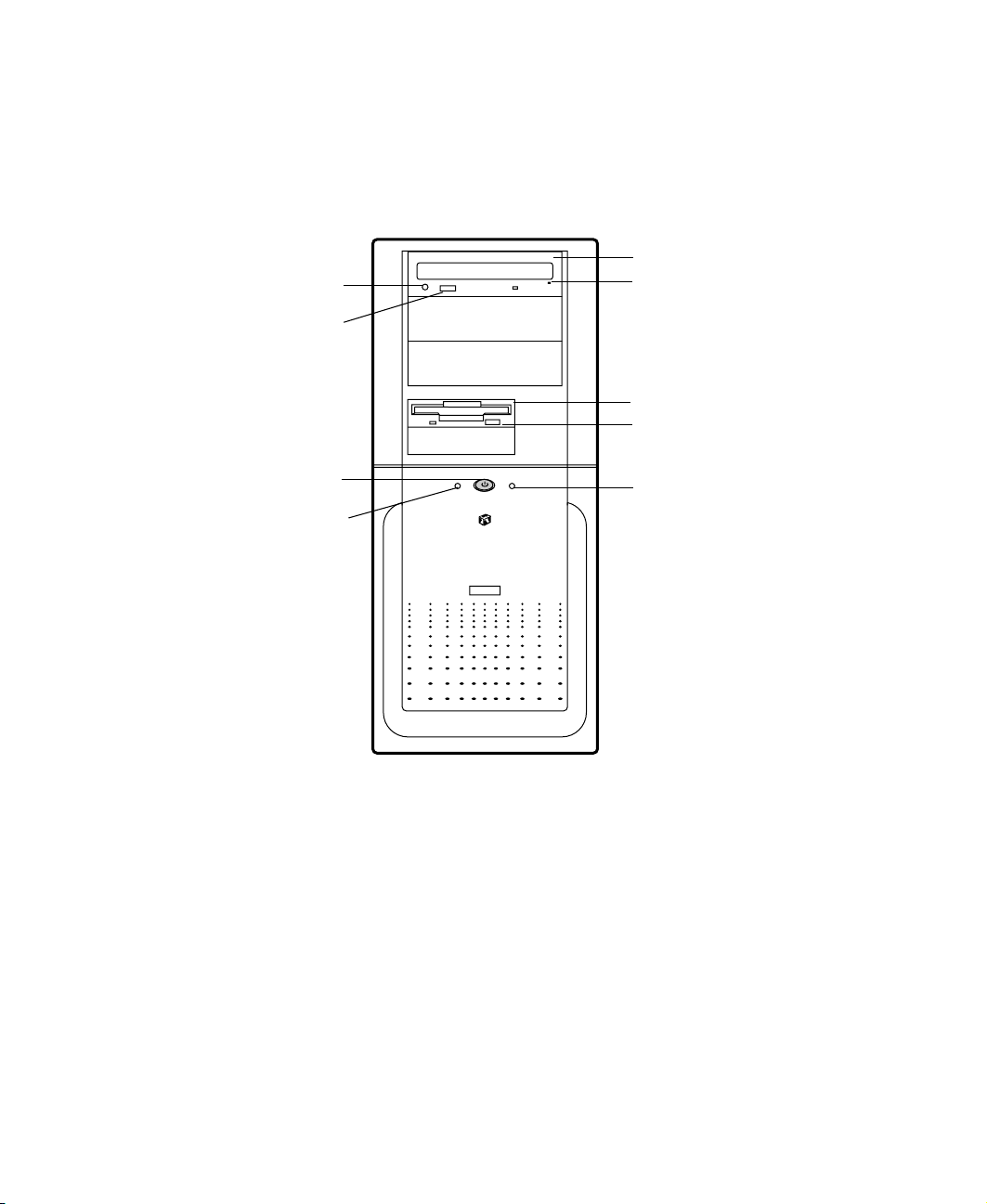
The front panel of the mid-tower case includes the following features:
Audio-out jack
CD-ROM volume
control
Power button and
Power-on LED
Hard drive LED
CD/DVD drive
CD/DVD eject
button
Diskette drive
Diskette
eject button
Reset button
Audio-out jack connects headphones or powered speakers that you use to
listen to an audio CD (directly from the CD/DVD drive).
CD/DVD volume control controls the volume of an audio CD.
Power button turns the computer on and off.
Power on LED lights when the computer is turned on. The green light means
your computer is using full power. The amber light means your computer is
in power conservation mode.
Hard drive LED lights when the hard drive is active.
System Features
2
Page 10

CD/DVD drive plays data or audio CDs.
CD/DVD eject button ejects a CD from the CD/DVD drive.
Diskette drive writes to and reads from 3.5-inch, 1.44 MB diskettes.
Diskette eject button ejects diskettes from the diskette drive.
Reset button restarts a system that has become non-responsive.
Front panel
3
Page 11
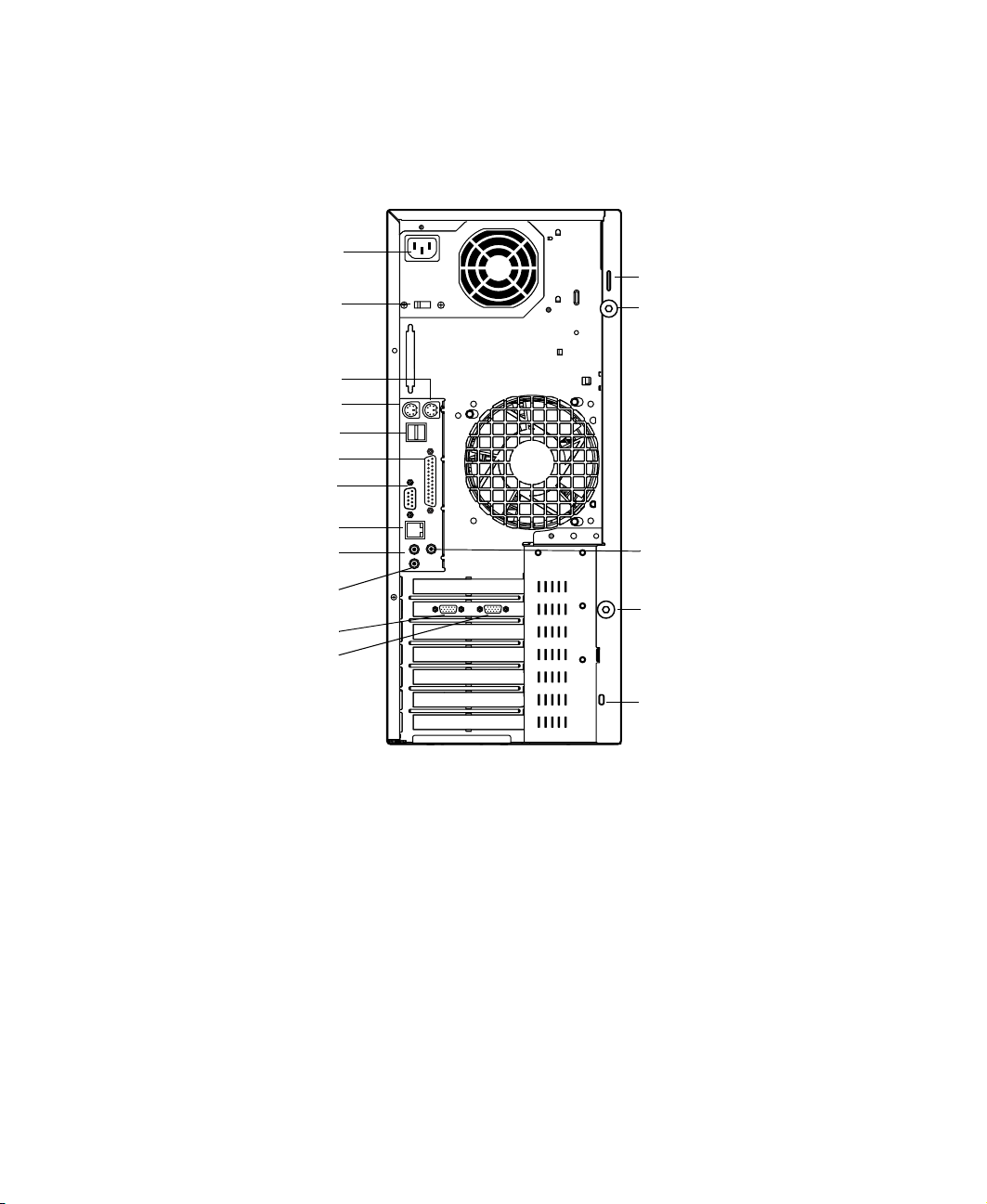
Rear panel
The mid-tower case rear panel includes the following Input/Output (I/O)
ports, connectors, and switches:
Power connector
Voltage selector
Mouse port
Keyboard port
USB ports
Parallel port
Serial port
RJ-45 LAN
connector
Audio Line-out
Microphone-in
Secondary video
port
Primary video port
Padlock tab
Thumbscrew
Audio Line-in
Thumbscrew
Voltage selector sets the voltage for your area, either 115 V or 230 V.
Power connector connects the computer power cord. The other end of the
power cord plugs into an AC outlet or power strip.
Mouse port connects a PS/2-compatible mouse.
Keyboard port connects a Personal System/2
USB ports connect external Plug-and-Play devices, such as keyboards and
pointing devices, that are automatically configured when they are plugged
into the computer through one of these ports.
Parallel (printer) port connects a printer or other parallel device.
System Features
4
Kennsington
lock slot
®
(PS/2) compatible keyboard.
Page 12

Serial port connects to a serial device.
RJ-45 LAN connector lets you connect to a network, and the adjacent
Indicator LEDs show LAN activity (yellow) and 100 Mbit speed (green).
Microphone-in, Audio Line-out, and Audio Line-in jacks connect audio
devices such as speakers, tape players, and microphones.
Secondary video port connects the second monitor interface cable.
Primary video port connects the first (or only) monitor interface cable.
Padlock tab permits the use of a padlock to secure the system. To use the
padlock tab it must be removed from it’s shipping position and reinstalled
in the active position, as shown below.
Active position
Shipping position
Thumbscrews must be loosened to remove the cover from the system.
Kennsington lock slot lets you use a cable lock to secure the system.
Rear panel
5
Page 13

System board
The following figure and list identify system board components.
AH
AF
AD
AB
AK
AJ
AI
AG
AE
Y
AC
AA
A
Z
C
B
D
E
F
G
H
I
J
K
L
M
N
O
P
Q
R
S
A
B
C
D
E
System Features
6
X
W
Processor fan 1 connector
Processor fan 2 connector
Processor slot 1
Processor slot 2
Processor fan 3 connector (not used)
U
V
T
Page 14

Voltage regulator module (VRM) for second processor
F
ATX power connector
G
Supplementary AGP Pro50 power connector
H
Auxiliary power connector
I
RIMM slots 1 and 2 (Channel A)
J
AGP (accelerated graphics processor) slot
K
SCSI LED connector
L
Diskette drive connector
M
Secondary IDE connector
N
Primary IDE connector
O
Internal speaker
P
Front system fan connector
Q
Front panel connector
R
Front chassis intrusion connector (not used)
S
Auxiliary LED connector
T
Configuration jumper (J1F2)
U
Internal MIDI connector
V
Telephony connector
W
CD/DVD audio connector
X
PCI slots (5)
Y
Battery
Z
System fan (not used)
AA
Rear chassis intrusion connector
AB
Rear system fan
AC
RIMM slots 3 and 4 (Channel B)
AD
Microphone-in connector
AE
System board
7
Page 15

Audio line-in (right) and Audio line-out (left) connectors
AF
RJ-45 Ethernet LAN connector and LEDs
AG
Serial port
AH
Parallel port
AI
USB ports
AJ
PS/2 Mouse and Keyboard ports
AK
System Features
8
Page 16

System Setup
Setting up your system
Use the instructions on the poster that came with your system to assemble
your system. You can prepare a safer working environment before assembling
your system by following the guidelines listed below.
Provide a clean, flat, and stable surface for your system. Allow at
■
least 12 inches at the rear of the computer for cabling and air
circulation.
Obtain a grounded (three-prong) AC surge-protected power strip.
■
A surge-protected power strip helps protect against AC line spikes.
Protect your system from extreme temperature and humidity. Do
■
not expose your system to direct sunlight, heater ducts, or other
heat-generating objects.
Keep your computer away from equipment that generates magnetic
■
fields, such as unshielded stereo speakers. Even a telephone placed
too close to the computer may cause interference.
Plug the computer into a wall outlet or power strip that is easily
■
accessible. When you turn off the computer with the power button,
some electricity still flows through the computer. To remove all
power from the computer, you need to unplug the power cord.
2
Important
Keep the computer boxes and packing material, in case
you need to send the computer to Gateway for repairs. If
you return your computer in different packaging, your
warranty may be void.
Setting up your system
9
Page 17

Starting your system
Before you start your system for the first time:
Make sure that the voltage selector switch on the back of the
■
computer is still set to the correct voltage for your area. This switch
is set at the factory to the correct voltage (see “Rear panel” on
page 4 for voltage selector switch location).
Make sure all cables are firmly connected to the proper ports on
■
the rear panel of the computer.
Caution
Make sure the computer and monitor are plugged into an AC outlet
■
or power strip and that the power strip is turned on.
Make sure your computer and peripherals are turned off
and unplugged from the power outlet when you connect
peripherals to the computer.
To start the system:
If you have connected the system components to a power strip, make
1
sure all the system components are turned off, then turn on the power
strip.
Turn on the monitor by pressing its power button.
2
System Setup
10
Page 18

Turn on the computer by pressing its power button. The light-emitting
3
diode (LED) in the power button is lit when the power is on.
Power button
and power LED
Turn on any other components connected to the computer, such as
4
speakers, a printer, or a scanner.
If nothing happens when you turn on the system:
Recheck the power cables to make sure that they are securely
■
plugged in and that your power strip (if you are using one) is
plugged in and turned on.
Make sure the monitor is connected to the computer, plugged into
■
the power strip or AC outlet, and turned on. You may also need
to adjust the brightness and contrast controls on the monitor.
Important
Wait until the startup procedure is finished before loading
a diskette in the diskette drive, or the computer may search
the diskette for startup information.
Starting your system
11
Page 19

Understanding the Power-On Self-Test
When you turn on your computer, the power-on self-test (POST) routine
checks the system memory and components. To see this information on the
screen, press T
count.
The system displays an error message if POST finds any problems. Write down
the error message that appears. If you continue to experience problems, this
error message may help technical support diagnose the cause.
during POST. Press ESC to bypass the remaining memory
AB
Setting up the operating system
The first time you start your computer, the operating system takes a few
minutes to set up.
Refer to your software documentation for specific questions regarding
software.
To complete the operating system setup:
After the computer starts, the start-up wizard opens. Continue by clicking
1
.
Next
Type the requested information in the appropriate text boxes. When you
2
have finished typing the information, continue by clicking
Next
.
Continue following the instructions and selecting options in the start-up
3
wizard dialog boxes, clicking
the wizard tells you to restart your computer.
Most of the dialog boxes that open in the start-up wizard have a button
that takes you back to previous dialog boxes, in case you need to change
or correct the information you typed.
Restart your system. The setup is complete.
4
System Setup
12
to move through the dialog boxes, un til
Next
Page 20

Turning off your system
Every time you turn off your system, shut down the operating system first.
You may lose data if you do not follow the proper procedure.
To turn off your system in Windows NT:
1
Click
Down
Start
.
, then click
Shut down the computer?
(Windows NT), then select
Shut
Click OK. The computer turns off. If you see a message saying
2
to turn off your computer
Turn off the monitor and peripherals.
3
Warning
, turn off the computer by pressing the power button.
When you turn the computer off by pressing the power
button, some electric current still flows through the
computer. Before opening the computer case or
connecting or removing any peripherals, turn off the
computer, then unplug the power cord and modem cord
(if installed).
It is now safe
Turning off your system
13
Page 21

Resetting your system
If your computer does not respond to keyboard or mouse input, you may have
to close a program or programs that may not be responding. If closing
unresponsive programs does not restore your computer to normal operation,
you may have to reset the system.
To reset your system in Windows NT:
Press C
1
that is not responding.
TRL+ALT+DEL
. A window opens that lets you to close a program
Click
2
3
4
As a part of the regular startup process, a program to check the disk status
runs automatically. When the checks are finished, Windows starts.
Task Manager
Close the program by clicking
If the computer does not respond, press the reset button to restart the
computer.
, then select the program that is not responding.
End Task
.
System Setup
14
Page 22

Case Access
Preventing static electricity
Before opening the computer case, read and follow these precautions to
prevent damage from static electricity. When opening your computer case,
always perform the following procedure.
3
Caution
To prevent static electricity discharge:
Turn off the computer power.
1
Touch a bare metal surface on the back of the computer.
2
Unplug all power cords from AC outlets and disconnect the modem cable
3
(if installed).
Static electricity can permanently damage electronic
components in your computer. Prevent electrostatic
damage to your computer by following static electricity
precautions every time you open your computer case.
Preventing static electricity
15
Page 23

Also follow these static electricity precautions:
Avoid static-causing surfaces such as plastic and styrofoam in your work
■
area.
Remove the parts from their antistatic bag or container only when you
■
are ready to use them. Do not lay parts on the outside of an antistatic
bag or container because only the inside provides antistatic protection.
Always hold cards by their edges and their metal mounting brackets.
■
Avoid touching components on the cards and the edge connectors that
connect to expansion slots. Never slide cards or other parts over any
surface.
Case Access
16
Page 24

Opening the case
Important
To work on the internal components of the computer, you must open the
case, which has two removable parts:
A left side cover panel that permits access to the interior of the case
■
A bezel that covers the front of the chassis
■
Because the components inside your computer are extremely sensitive to static
electricity, make sure to follow the precautions at the beginning of this chapter
for avoiding static electricity damage. Only qualified personnel should open
the system for maintenance. If you feel you are qualified to maintain the
system yourself, make sure you are properly grounded before opening the
system chassis.
Warning
All references to front, rear, left or right on the computer
are based on the computer being in a normal, upright
position, as viewed from the front.
Avoid exposure to dangerous electrical voltages and
moving parts, by turning off your computer and unplugging
the power cord and modem cable (if installed) before
removing the chassis cover.
To remove the left side cover panel:
Turn off the computer and disconnect all power cords.
1
Remove the thumbscrews from the back of the side panel and unlock
2
the chassis lock (if applicable).
Opening the case
17
Page 25
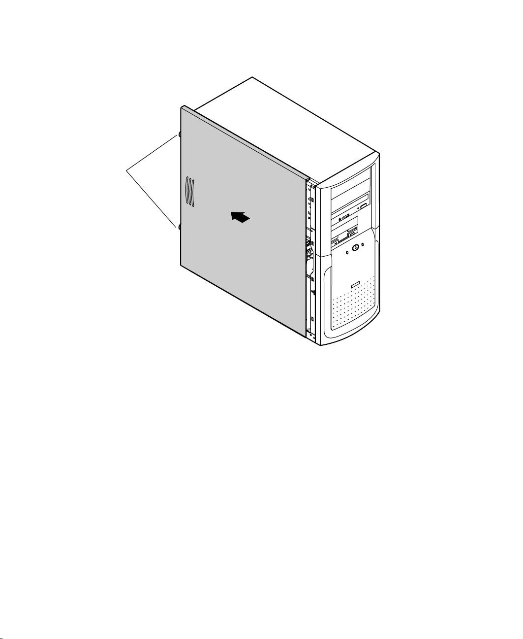
3
Thumbscrews
Slide the left side panel to the rear (approximately 3/4-inch), disengaging
the retaining tabs on the top edge of the panel from the top of the chassis.
Lift the panel up and away from the chassis.
4
Case Access
18
Page 26
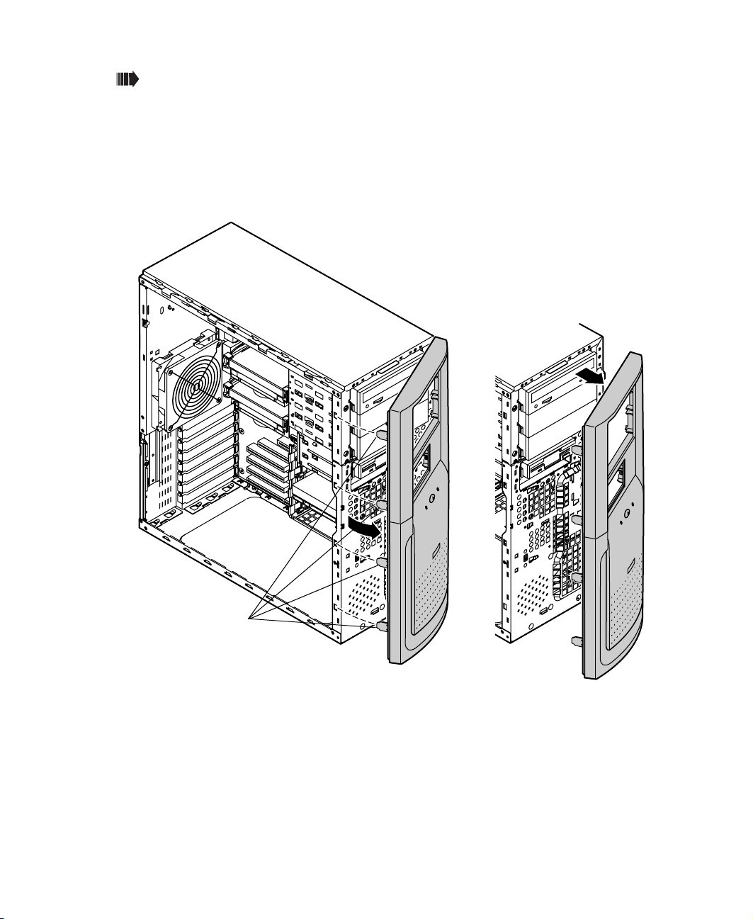
To remove the bezel:
With the left side panel removed, disengage the retention tabs on the
1
left side of the bezel by prying outward on each tab.
Swing the bezel out from the front of the chassis and disengage the hinge
2
tabs on the right side of the bezel by moving the bezel to the right.
Remove the bezel.
3
RetentionTabs
Opening the case
19
Page 27

Closing the case
Replace the chassis cover as soon as you finish installing or removing
components so that dust and dirt (which can damage the computer) do not
collect inside the computer.
To replace the bezel:
Holding the bezel at an angle to the front of the chassis, place the hinge
1
tabs on the right side of the bezel in the appropriate slots in the front
of the chassis.
Swing the left side of the bezel toward the chassis until the retaining tabs
2
snap into place.
Four hinge tabs are located
on the right side of the bezel
and are not visible in this
illustration
Case Access
20
Page 28

To replace the chassis cover:
Holding the left side panel at an angle to the chassis and 3/4-inch to the
1
rear, engage the retaining strip on the bottom edge of the panel with the
lip at the bottom edge of the chassis.
Swing the top of the panel toward the chassis, engaging the retaining
2
tabs on the top edge of the side panel with the slots on the chassis.
Slide the panel toward the front of the chassis 3/4-inch, securing it into
3
place.
Reinstall the thumbscrews and lock the case (if applicable).
4
Closing the case
21
Page 29

Case Access
22
Page 30

System Components
The system board
The system board is the heart of the computer, which integrates the other
elements of the system, such as the processor, memory, storage, networking,
and communications, and lets them operate in a coordinated and useful way.
Removing the system board
The system board is mounted on stand-off retention hooks on the right side
of the chassis. The board is secured by two screws, one located on the
back-right of the chassis, and one located inside the case.
Important
To remove the system board:
Turn off the system and disconnect the power cord, modem cord (if
1
installed), and all external peripheral devices.
All references to front, rear, left or right on the computer
are based on the computer being in a normal, upright
position, as viewed from the front.
4
Open the case by following the instructions on page 17. (See “Preventing
2
static electricity” on page 15.)
Place the chassis gently on its right side.
3
The system board
23
Page 31

Remove all expansion cards from the system board (See “Adding an
4
expansion card” on page 34).
Disconnect all cables from the system board, including the power cables
5
from the power supply. Note where the cables are connected.
Remove the retaining screw securing the board to the right side of the
6
chassis.
Remove retaining
screw from this hole
System Board -
components
Rear
removed for clarity
Front
System Components
24
Page 32

Loosen the retaining screw at the back (right side) of the chassis.
7
System board
retaining screw
Slide the system board toward the front of the chassis slightly, to
8
disengage it from the stand-off retention hooks (see illustration under “To
install the system board:”), then remove it carefully.
Remove the system board mounting bracket (shown below) and place the
9
board in a static-free bag or container.
The system board
25
Page 33

To install the system board:
Install the system board mounting bracket on the rear edge of the system
1
board by inserting the tabs into the corresponding holes in the board
and rotating the bracket into place.
Tabs
Mounting bracket
System Components
26
Page 34

Holding the system board by the top and bottom edges, place it in the
2
case by aligning the mounting holes on the board with the stand off
(threaded) and stand off retention hooks on the right side of the case.
Holding the system board in place, tighten the retaining screw on the
3
right rear of the case.
Replace the retention screw previously removed from the system board,
4
then tighten the screw until the board is secured.
Reconnect peripherals, the modem cord, and the power cord, then turn
5
on the system.
The system board
27
Page 35

Replacing or adding a processor
The system is compatible with the Intel® Pentium® III 667 and 733 MHz and
faster processors with 133 MHz front-side bus (FSB). Up to two processors may
be installed in the system.
When replacing a processor, or adding an additional processor, order a
Pentium III processor upgrade kit from Gateway. The kit includes the Pentium
III processor, a fan/heatsink, and a disposable electrostatic wrist strap.
Caution
A heatsink or fansink must be installed on each processor.
Installing a processor without a heatsink or fansink could
result in damage to, or failure of the processor.
To replace a processor:
Turn off the system and disconnect the power cord and modem cord (if
1
installed) and all other external peripheral devices.
Open the case by following the instructions on page 17. (See “Preventing
2
static electricity” on page 15.)
Disconnect the power supply cable of the processor fan from the CPU
3
fan connector on the system board.
Place the head of a flat-bladed screwdriver behind the tab on one side
4
of the processor retention bracket holding the processor to be removed.
Screwdriver
Push the handle of the screwdriver toward the processor. When the tab
5
that locks the processor in place opens, lift up slightly on the side of the
processor.
System Components
28
Ta b
Page 36

Repeat the previous two steps for the other side of the processor.
6
Pull the processor up and out of the slot.
7
Align the new processor with the processor slot (note that the processor
8
slot is keyed so the processor can only be installed one way) and press
firmly to install it.
The system board
29
Page 37

Reconnect the power supply cable of the processor fan to the CPU fan
9
connector on the system board.
Close the case, as described in Chapter 3.
10
Reconnect the power cord and all other cords you removed, then turn
11
on the system.
To add an additional processor:
Turn off the system and disconnect the power cord and modem cord (if
1
installed) and all other external peripheral devices.
Open the case by following the instructions on page 17. (See “Preventing
2
static electricity” on page 15.)
Remove the terminator card from the second processor slot to make room
3
for the additional processor.
Align the new processor with the processor slot (note that the processor
4
slot is keyed so the processor can only be installed one way) and press
firmly to install it.
Connect the power supply cable of the processor fan to the second CPU
5
fan connector on the system board (See “System board” on page 6 for
location).
Close the case, as described in Chapter 3.
6
Reconnect the power cord and all other cords you removed, then turn
7
on the system.
Adding or replacing memory
The Rambus Dynamic Random Access Memory (RDRAM) Rambus In-line
Memory Modules (RIMMs) supported by your system board conform to the
following standards:
32 MB, 64 MB, 128 MB, 256 MB, and 512 MB ECC or non-ECC RIMMs
■
Single- or double-sided configurations
■
2 GB maximum system memory
■
When you are selecting and installing RIMMs, keep the following in mind:
System Components
30
Page 38

RIMM modules must be installed symetrically into both channels, that
■
is, if a RIMM is installed in RIMM-1 (Channel A), the same size, density,
type, and speed RIMM must be installed in RIMM-3 (Channel B), likewise
for RIMM-2 and RIMM-4. If RIMMs are not installed in this manner, the
computer will not boot. Using the encoded part numbers on the RIMM
modules is the best way to make sure that the parts are the same.
RIMM-3
RIMM-4
RIMM-1
RIMM-2
To optimize memory performance, RIMM-1 and RIMM-3 must be
■
Channel B
Channel A
populated first.
ECC memory cannot be combined with non-ECC memory.
■
Continuity Modules (CRIMMs) are required in all blank memory slots. If
■
CRIMMs are not installed in blank slots, the computer will not boot.
No jumper settings are required for the memory size or type because this
■
information is automatically detected by the BIOS.
At the time this manual was printed, some RIMM module configurations
■
were not available for testing or sale. The following chart is not intended
to imply either availability or compatibility. As new RIMM configurations
become available, check with Gateway’s website (www.gateway.com) for
updated information.
RIMM Modules To ta l
Memory
2 - 32 MB RIMMs, 2 - CRIMMs 64 MB
4 - 32 MB RIMMs, 128 MB
2 - 64 MB RIMMs, 2 - 32 MB RIMMs 192 MB
4 - 64 MB RIMMs 256 MB
2 - 96 MB RIMMs, 2 - 64 MB RIMMs 320 MB
The system board
31
Page 39

4 - 96 MB RIMMs 384 MB
2 - 128 MB RIMMs, 2 - 96 MB RIMMs 448 MB
4 - 128 MB RIMMs 512 MB
2 - 256 MB RIMMs, 2 - 128 MB RIMMs 768 MB
4 - 256 MB RIMMs 1 GB
2 - 512 MB RIMMs, 2 - 256 MB RIMMs 1.5 GB
4 - 512 MB RIMMs 2 GB
To add or remove RIMMs:
Turn off the system and disconnect the power cord and modem cord (if
1
installed) and all other external peripheral devices.
Open the case by following the instructions on page 17. (See “Preventing
2
static electricity” on page 15.)
System Components
32
Page 40

If you are adding a RIMM, pull open the socket clamps on each side of
3
the RIMM socket and remove the CRIMM.
Socket clamps
If you are replacing a RIMM, pull open the socket clamps on each side
4
of the RIMM socket, then lift the RIMM out of the socket.
RIMM
Store the RIMM in a static-free container.
5
The system board
33
Page 41

Insert the new RIMM into the socket and align the two notches in the
6
RIMM with the two notches in the RIMM socket.
RIMM
Gently press the RIMM into the socket until it’s firmly seated. Inserting
7
the RIMM automatically locks each of the socket clamps on each end of
the RIMM.
Close the case, as described in Chapter 3.
8
Reconnect peripherals, the modem cord, and the power cord, then turn
9
on the system.
Adding an expansion card
The E-5400 computer has five PCI expansion slots on the system board, which
may be used for a variety of add-on cards. These cards may include a SCSI
controller card, a modem, a high-end sound card, or an additional IDE
controller card. The computer also has a single AGP slot which contains the
graphics controller card for the system.
To add an expansion card:
Set any jumpers and switches on the card, if required in the card
1
instructions. Turn off the computer, disconnect the power cord, modem
cord (if installed), and all external peripheral devices.
System Components
34
Page 42

Open the case by following the instructions on page 17. (See “Preventing
2
static electricity” on page 15.)
Locate an available slot and remove the slot cover by removing the screw
3
that secures it to the back of the chassis.
Insert the bottom edge of the expansion card (the keyed edge with the
4
contacts) into the slot on the system board and push in firmly to seat
the card.
Screw
After seating the card firmly, use the screw you removed to secure the
5
card to the rear of the chassis.
Connect any cables to the card (see card documentation for proper
6
jumper settings and cable orientation).
Close the case, as described in Chapter 3.
7
Reconnect peripherals, the modem cord, and the power cord, then turn
8
on the system.
The system board
35
Page 43

You may need to reconfigure your system after installing some expansion
cards. You may also need to install software that came with the card. Check
the card documentation for additional information.
Replacing the battery
The battery provides power for the system real-time clock and CMOS memory,
which holds the system configuration information.
If your battery is failing you may notice your system clock slowing down and
giving you the incorrect time. If so, open the BIOS Configuration Manager
and write down all the values in the various tabs before replacing the battery.
Replacing the battery resets the BIOS Configuration Manager to its default
values.
Caution
There is a danger of explosion if the battery is incorrectly
replaced. Replace the battery only with the same or
equivalent type recommended by the manufacturer.
Dispose of used batteries according to the manufacturer’s
instructions.
To replace the battery:
Restart the computer and start the BIOS Configuration Manager program
1
by selecting
Write down the CMOS values from the
2
Integrated Floppy, Peripheral Ports, Power Events, General
in the BIOS Configuration Manager so you can reenter them after you
replace the battery. For more information about the BIOS Configuration
Manager program, see “Using the BIOS Configuration Manager” on
page 65.
Turn off the computer, disconnect the power cord, modem cord (if
3
installed), and all external peripheral devices.
Open the case by following the instructions on page 17. (See “Preventing
4
static electricity” on page 15.)
Locate the battery on the system board (see “System board” on page 6).
5
The battery is circular and has the positive pole mark (+) on the top.
Enter Setup
when you are prompted to do so.
Boot Options, Integrated IDE,
and
Security
tabs
System Components
36
Page 44

Using a small, flat-bladed screwdriver, carefully remove the battery from
6
its socket on the system board.
Press the new battery in the socket with the positive pole up. Be sure you
7
have pressed the battery down far enough for it to contact the base of
the socket (it should snap into place).
Close the case, as described in Chapter 3.
8
Reconnect peripherals, the modem cord, and the power cord, then turn
9
on the system.
If the CMOS data is not correct, change the information in the BIOS
10
Configuration Manager using the data you recorded in Step 2.
Troubleshooting the battery installation
If you have problems after installing the new battery, try each of the items
listed below, restarting the computer after each try.
Turn off the computer and make sure that all exterior cables are
■
attached and secured to the correct connectors.
Make sure that all power switches are on. If the computer is plugged
■
into a power strip or surge protector, make sure it is turned on also.
Enter the BIOS Configuration Manager program and compare the
■
settings on the screen with your notes or the system hardware
manuals. Correct any discrepancies.
The system board
37
Page 45

Turn off the computer, remove the cover, and make sure that all
■
cables inside the case are attached securely. Also, make sure that
the colored cable edges are aligned correctly and that the
connectors didn’t miss any pins. Disconnect and reconnect the
cables. Close the case as described in Chapter 3, reconnect the
modem and power cords, then turn on the computer.
Turn off the computer, remove the cover and, if you have the
■
proper test equipment, make sure that the new battery has power.
(Although unlikely, your new battery may be defective.) Close the
case as described in Chapter 3, reconnect the modem and power
cords, then turn on the computer.
System Components
38
Page 46

Preparing to replace or add a drive
One 3.5-inch diskette drive, one 3.5-inch hard drive, and one CD-ROM drive
are included with your computer. You can add additional drives of the
following types:
Half-height 3.5-inch diskette drives - The floppy controller supports
■
up to two diskette drives, one of which is the 3.5-inch diskette drive
that comes with your computer.
Half-height 3.5-inch hard drives - The system board has two IDE
■
connectors that support up to two drives each, for a total of four
IDE drives. To use another type of hard drive, such as a SCSI drive,
an add-in card must be installed.
Half-height 3.5-inch tape storage or disk storage devices.
■
Half-height 5.25-inch devices.
■
5.25-inch drive cage
Middle 3.5-inch
drive cage
Bottom 3.5-inch
hard drive cage
Preparing to replace or add a drive
39
Page 47

As you prepare to install drives, keep the following in mind:
To remove and install drives, you need a grounding wrist strap and
■
a Phillips screwdriver.
If you remove a drive, place it in an antistatic bag or container.
■
Before you install a drive, see the drive’s documentation for
■
information on configuring the drive, setting any jumpers on the
drive, and attaching cables to the drive.
If you are installing a drive that uses an add-in controller, install
■
the add-in card before you install the drive.
IDE hard drives can be configured as single, master, or slave. IDE
■
CD-ROM dr ive s ca n be configu red as master o r slav e. C onfig ure the
drives by using the drive-select jumpers located on the drives.
If only one drive is attached to a controller cable, configure the
■
drive as single if it is a hard drive or master if it is a CD-ROM drive.
If two drives of any type are attached to the cable, configure one
as master and one as slave.
You may need to configure the drives you install using the BIOS
■
Configuration Manager program. Select
Enter Setup
access the BIOS Configuration Manager program.
at start up to
System Components
40
Page 48

Drive cabling information
Three drive cables are included with your system. The diskette drive connector
cable is used to connect diskette drives and other non-IDE devices such as
tape backup drives. The two IDE connector cables are used to connect IDE
devices such as CD-ROM drives and hard drives.
If you want to add additional drives, you can replace the drive connector
cables with ones that contain three connectors, which would let you add a
total of four IDE devices or two diskette drives.
To floppy
connector on
system board
End of data
cable with
twisted
conductors
To diskette
drive that
came with
your system
Diskette Drive
Connector Cable
IDE Connector Cables (two cables)
Blue to
secondary IDE
connector on
system board
80 wire cable
Gray to
CD-ROM
drive
Black to
CD-ROM drive
Blue to
primary IDE
connector
on system
board
Gray to
IDE drive
Black to
IDE drive
Preparing to replace or add a drive
41
Page 49

3.5-inch diskette or CD/DVD drives
Removing and replacing the 3.5-inch diskette or CD/DVD drive
To replace the drives:
Turn off the system and disconnect the power cord and modem cord (if
1
installed) and all other external peripheral devices.
Open the case by following the instructions on page 17. (See “Preventing
2
static electricity” on page 15.)
Remove the bezel, as described in “To remove the bezel:” on page 19.
3
Locate the 3.5-inch diskette or 5.25-inch CD/DVD drive.
4
Remove the power and data cables from the back of the drive, noting
5
their location and orientation. (You will reconnect these cables after you
install the new drive.)
System Components
42
Page 50

Both the 3.5-inch diskette drive and 5.25-inch CD/DVD drives are secured
in the chassis by sets of removable rails. The rails let the drives slide into
and out of the guides in the front bays. Extra rails are included with your
system and are clipped to the outsides of the drive cages, inside the case.
Disengage the rail locking tabs by pressing inward on both front rail
6
extensions, then move the drive slightly out of the bay by pushing on
the back of the drive. Pull the drive out of the chassis.
Remove the rails on both sides of the drive and snap them onto the new
7
drive in the same positions. Make sure the front rail extensions are
towards the front of the drive.
R
CD/DVD Drive
L
R
3.5-inch
Diskette Drive
L
Important
Align the rails with the appropriate open bay, and slide the drive into
8
The rails on the 3.5-inch drive are different from those on
the CD/DVD drive. Make sure you install the correct rails
on each drive.
the bay until the locking tabs snap into place.
Connect the power and data cables, making sure the cables match their
9
original position. (See your drive documentation for proper drive jumper
settings and cable orientation.)
Close the case, as described in Chapter 3.
10
Reconnect the power and modem cords, then turn on the system.
11
3.5-inch diskette or CD/DVD drives
43
Page 51

Installing an additional 3.5-inch device
The second, externally accessible 3.5-inch drive bay can be used to install a
3.5-inch device such as a tape drive, a 100 MB or 120 MB disk storage device,
or an additional 3.5-inch diskette drive. Extra sets of rails are included with
your system (clipped to the drive cage) and are used for the installation. You
will have to purchase an additional cable with three connectors and of
sufficient length to connect the existing devices and the new device to the
connector on the system board.
To install an additional device in the 3.5-inch drive bay:
Turn off the system and disconnect the power cord and modem cord (if
1
installed) and all other external peripheral devices.
Open the case by following the instructions on page 17. (See “Preventing
2
static electricity” on page 15.)
Remove the bezel, as described in “To remove the bezel:” on page 19.
3
Remove the plastic bezel insert covering the open bay by disengaging the
4
retaining tab and pushing the insert out from the back of the bezel. Save
the insert so that you can replace it if you remove the added device.
Remove the metal EMI shield from the front of the drive bay, if installed,
5
by unscrewing the retaining screw on the right side of the shield and
swinging it out to disengage it from the chassis..
Caution
Snap the rails onto the drive, making sure the front rail extensions are
6
towards the front of the device.
System Components
44
Your system was designed to adhere to electromagnetic
interference requirements and the shield is an integral part
of the system. Installing an approved device should
continue to maintain those standards. If you remove the
device you should reinstall the shield.
Page 52

Align the rails with the open bay, and slide the drive into the chassis until
7
the locking tabs snap into place.
Connect the power and data cables to the back of the drive. (See drive
8
documentation for proper drive jumper settings and cable orientation.)
Close the case, as described in Chapter 3.
9
Reconnect the power and modem cords, then turn on the system.
10
Run the configuration software, if required.
11
3.5-inch diskette or CD/DVD drives
45
Page 53

Installing an additional 5.25-inch device
Two additional, externally accessible 5.25-inch drive bays can be used to
install additional 5.25-inch devices such as a CD-ROM writer or a tape backup.
Extra sets of rails are included with your system (clipped to the drive cage)
and are used for the installation. You may need to purchase an additional cable
of sufficient length to connect the existing devices and the new device to the
connector on the system board.
To install an additional device in the 5.25-inch drive bay:
Turn off the system and disconnect the power cord and modem cord (if
1
installed) and all other external peripheral devices.
Open the case by following the instructions on page 17. (See “Preventing
2
static electricity” on page 15.)
Remove the bezel, as described in “To remove the bezel:” on page 19.
3
Remove the plastic bezel insert covering the open bay by disengaging the
4
retaining tab and pushing the insert out from the back of the bezel.
System Components
46
Page 54

Remove the metal EMI shield from the front of the drive bay, if installed,
5
by placing a finger in the hole on the left side of the shield and pulling
out to disengage it from the chassis.
Metal EMI
shield
Pull out on the
left side of the
metal EMI shield
Caution
Snap the rails onto the drive, making sure the front rail extensions are
6
Your system was designed to adhere to electromagnetic
interference requirements and the shield is an integral part
of the system. Installing an approved device should
continue to maintain those standards. If you remove the
device you should reinstall the shield.
towards the front of the device.
3.5-inch diskette or CD/DVD drives
47
Page 55

Align the rails with the bay, and slide the drive into the chassis until the
7
locking tabs snap into place.
Connect the power and data cables, making sure the cables match their
8
original position. (See your drive documentation for proper drive jumper
settings and cable orientation.)
Close the case, as described in Chapter 3.
9
Reconnect the power and modem cords, then turn on the system.
10
Run the configuration software, if required.
11
System Components
48
Page 56

Hard drives
Removing and replacing the hard drive
The hard drive that is included with your system is mounted in the bottom
drive cage in the chassis.
To replace the hard drive:
Turn off the system and disconnect the power cord and modem cord, if
1
installed.
Open the case by following the instructions on page 17. (See “Preventing
2
static electricity” on page 15.)
Locate the 3.5-inch hard drive in the bottom drive cage.
3
Remove the power and data cables from the hard drive.
4
Grip the plastic mounting rails firmly with thumb and index finger and
5
pull the drive carefully straight out of the drive cage.
Remove the small, plastic mounting rails from the hard drive.
6
Hard drives
49
Page 57

Place the old drive in an antistatic bag or container, then place the new
7
hard drive on a static-free surface with the top up and the connectors
facing you.
Install two small, plastic drive mounting rails (“L” rail on the left and
8
“R” rail on the right) to the new hard drive, making sure the front rail
extensions are towards the front of the device. Align the wire retention
clips to the mounting holes in the drive and pressing the rails to the sides
of the drive.
“R” rail
R
“L” rail
Align the rails with an open bay in the bottom drive cage, and slide the
9
drive into the cage until the locking tabs snap into place (be sure that
the data and power connectors on the drive face outward).
Connect the power and data cables to the drive. (See drive documentation
10
for proper drive jumper settings and cable orientation.)
Close the case, as described in Chapter 3.
11
Reconnect the power and modem cords, then turn on the system.
12
L
Installing an additional hard drive
The system comes equipped with a drive cage that will accept additional
internal hard drives. You will have to purchase an IDE cable with three
connectors and of sufficient length to connect the existing hard drive and
the new drive to the IDE connector on the system board.
System Components
50
Page 58

To install an additional hard drive:
Turn off the system and disconnect the power cord and modem cord, if
1
installed.
Open the case by following the instructions on page 17. (See “Preventing
2
static electricity” on page 15.)
Place the new hard drive on a static-free surface with the top up and the
3
connectors facing you.
Install two small, plastic drive mounting rails (“L” rail on the left and
4
“R” rail on the right) to the new hard drive, making sure the front rail
extensions are towards the front of the device. Align the wire retention
clips to the mounting holes in the drive and pressing the rails to the sides
of the drive.
Align the rails with an open bay in the bottom drive cage, and slide the
5
drive into the chassis until the locking tabs snap into place.
Connect the data and power cables to the drive. (See drive documentation
6
for proper drive jumper settings and cable orientation.)
Close the case as described in Chapter 3.
7
Reconnect the power and modem cords, then turn on the system.
8
Hard drives
51
Page 59

Power supply
Removing and replacing the power supply
To remove the power supply:
Turn off the system and disconnect the power cord and modem cord, if
1
installed.
Open the case by following the instructions on page 17. (See “Preventing
2
static electricity” on page 15.)
Lay the case on its right side, if possible.
3
Locate and disconnect the power supply connectors from all internal
4
devices, including the 3.5-inch diskette drive, the CD-ROM drive and all
hard drives.
Locate and disconnect the main power supply connector to the system
5
board, by pressing on the tab to release the connector, then gently pulling
the connector from the board.
System Components
52
Page 60

Locate and remove the two supporting screws securing the power supply
6
to the top of the chassis.
Screws
Screws
While supporting the power supply with one hand, locate and remove
7
the two screws securing the power supply to the rear of the
chassis.Carefully lift the power supply out of the chassis.
To install the new power supply:
Before installing the new power supply, verify that it matches the one
1
you previously removed. The mounting holes should line up correctly,
and the specifications and power output connectors should be the same.
Make sure that the red voltage switch on the back of the new power
2
supply is set to the proper voltage for your area.
Place the new power supply in the proper position in the chassis and line
3
up the mounting holes with the holes in the chassis.
Power supply
53
Page 61

Replace the two screws securing the power supply to the back of the
4
chassis, leaving them slightly loose.
Replace the two supporting screws securing the power supply to the top
5
of the chassis, then tighten all screws.
Reconnect the power connectors to the system board and to all internal
6
devices.
Place the case upright, then close the case as described in Chapter 3.
7
Reconnect the power and modem cords, then turn on the system.
8
System Components
54
Page 62

System fans
Removing and replacing the system fans
The front system fan is mounted on the front of the bottom drive cage. The
rear system fan is mounted on a fan mounting bracket attached to the rear
of the system.
To remove the front system fan:
Turn off the system and disconnect the power cord and modem cord, if
1
installed.
Open the case by following the instructions on page 17. (See “Preventing
2
static electricity” on page 15.)
Remove the bezel, as described in “To remove th e bezel:” on page 19.
3
Disconnect the front fan power cable from the system board.
4
Remove the power and data cables from any hard drives mounted in the
5
bottom drive cage.
Remove the drives from the bottom drive cage and place them in
6
anti-static bags or containers.
System fans
55
Page 63

Remove the plastic card guide attached to the bottom drive cage by
7
depressing the locking tabs (from the rear of the guide) and pivoting the
top of the guide toward the back of the system. (You may have to remove
one or more add-in cards from the system board.)
Ta b
Remove the two screws securing the bottom drive cage to the front of
8
the chassis and the two screws securing it to the right side of the chassis.
System Components
56
Page 64

Slide the bottom drive cage toward the left side of the chassis, then toward
9
the back, disengaging it from the middle drive cage and the chassis.
Carefully remove the bottom drive cage from the chassis.
10
Remove the four screws securing the front system fan to the bottom drive
11
cage and lift the fan from the cage. Note the routing of the fan power
cable.
System fans
57
Page 65

To install the new front system fan:
Place the new front system fan into the recess in the front of the bottom
1
drive cage. Orient the fan with the label toward the inside of the chassis
(toward the system board), and the fan power cable to the right side of
the drive cage.
Secure the fan to the drive cage with the four screws previously removed.
2
Place the bottom drive cage into the chassis under the middle drive cage
3
and slide it forward so that the support tabs on top of the bottom cage
engage the middle drive cage, then slide it right to align the screw holes
with the holes on the front of the chassis.
Secure drive cage with the four screws previously removed. Make sure to
4
correctly route the fan power cable.
Replace the plastic card guide and any add-in cards removed previously.
5
Replace the hard drives into the bottom drive cage.
6
Replace the data and power cables on the hard drives.
7
Plug the fan power cable into the appropriate connector on the system
8
board.
Replace the bezel and close the case as described in Chapter 3.
9
Reconnect the power and modem cords, then turn on the system.
10
To remove the rear system fan:
Turn off the system and disconnect the power cord and modem cord, if
1
installed.
Open the case by following the instructions on page 17. (See “Preventing
2
static electricity” on page 15.)
Disconnect the rear fan power cable from the system board.
3
System Components
58
Page 66

Depress the two locking tabs on the plastic fan bracket (from the back
4
of the chassis), then move the fan bracket to the left (from the inside)
to disengage the four retaining tabs from the back of the chassis.
Retaining tab
Locking tab
Locking tab
Retaining tab
System fans
59
Page 67

Carefully remove the fan and bracket from the chassis.
5
Remove the fan from the bracket by carefully prying up on each corner
6
with a flat-bladed screwdriver.
Remove the fan guard by removing the four screws securing it to the fan.
7
To install the new rear system fan:
Install the fan guard on the new fan with the four screws you removed
1
from the old fan.
Place the new fan into the recess in the rear fan bracket and press it firmly
2
into place. Orient the fan with the fan label toward the rear of the chassis.
System Components
60
Page 68

Replace the fan bracket unit into the chassis by engaging the four
3
retaining tabs with the holes in the back of the chassis and sliding the
unit to the right until the two locking tabs click into place.
Plug the fan power cable into the appropriate connector on the system
4
board.
Close the case as described in Chapter 3.
5
Reconnect the power and modem cords, then turn on the system.
6
System fans
61
Page 69

Control panel
Removing and replacing the control panel
To remove the control panel:
Turn off the system and disconnect the power cord and modem cord, if
1
installed.
Open the case by following the instructions on page 17. (See “Preventing
2
static electricity” on page 15.)
Remove the bezel, as described in “To remo v e the bez e l :” on page 19.
3
After noting the position of the cables, disconnect the front panel
4
connector from J13J2 on the system board.
System Components
62
Page 70

Pull out on the retention tab and slide the control panel unit to the left,
5
then pull it away from the front of the chassis, taking care not to damage
the control panel cables or connectors as you pull them from the chassis.
Retention tab (shown
with part of bracket cut
away for clarity)
To install the new control panel:
Feed the control panel connector and cables through the opening in the
1
front of the chassis.
Noting the position of the cables, plug the control panel connector into
2
J13J2 on the system board.
Control panel
63
Page 71

Insert the mounting tabs of the control panel unit into the proper slots
3
on the front of the chassis, then slide the unit to the right until it locks
into place.
Replace the bezel and close the case as described in Chapter 3.
4
Reconnect the power and modem cords, then turn on the system.
5
System Components
64
Page 72

Using the BIOS Configuration Manager
About the BIOS Configuration Manager
The computer’s BIOS has a built-in configuration manager that lets you
configure several basic system characteristics. The settings are stored in
battery-backed RAM and are retained even when the power is off.
Enter the BIOS Configuration Manager by restarting the computer, then
selecting
Upon entering BIOS Configuration Manager, the screen on the following page
is initially displayed.
Enter Setup
Important
with your mouse when the Gateway Logo screen appears.
This BIOS will not display the usual system messages on
the screen when the system is first started. If you require
this information, you must enter the BIOS Configuration
Manager to obtain it.
5
About the BIOS Configuration Manager
65
Page 73

BIOS Configuration Manager
Help System Processors System Memory Boot Options System Even
BIOS Configuration Manager General Help
Copyright (c) 1999 Intel Corporation
Copyright (c) 1985-1998 American Megatrends Inc.
Tab Navigation:
Use the left mouse button or Left/Right Arrow keys to select a tab.
Use the scroll buttons (upper right corner) to display additional tabs.
Field Navigation:
Use the left mouse button or Tab and Shift + Tab keys to select a field.
Changing Settings:
Use the left mouse button to change field values or use the Space bar
for check boxes and Up/Down Arrow keys for list boxes.
Save/Exit:
Select the appropriate button on the Save/Exit tab.
The Esc key will activate the Save/Exit tab.
Tab Specific Help:
For tab-specific Help press F1 or the right mouse button.
< >
This BIOS Configuration Manager Help tab provides information on how to
navigate through the various tabs, as well as how to change settings and exit
the BIOS setup.
The BIOS Configuration Manager also has the following tabs available at the
top of the main screen. Each tab provides specific information or provides
access to specific options, as described in the following list:
Help
■
■
provides information on using the Configuration Manager.
System Processors
provides information on the processor with which
your system is configured, as well as the host bus speed.
System Memory
■
provides information on your system’s current memory
configuration.
Using the BIOS Configuration Manager
66
Page 74

Boot Options
■
gives you access to information and settings for boot features
and boot sequences.
System Event Log
■
provides information on event log capability and
validity, as well as event log options. Allows the user to view the event log.
Integrated IDE
■
lets you to enable or disable the integrated IDE controller.
Also lets you enable, disable or configure, primary and secondary drives.
Lets you change the spin delay.
Integrated Floppy
■
lets you enable or disable the integrated diskette drive
controller, provides a selection of drive size options, and lets you
write-protect the drive.
System BIOS
■
Peripheral Ports
■
provides information on the BIOS and SMBIOS versions.
lists all available peripheral ports and configuration
options for each.
Power Events
■
Time/Date
■
General
■
Security
■
Save/Exit
■
lets you enable or disable all power-on options.
shows current time and date and allows you to change both.
lets you configure general platform options.
gives you access to settings related to system access passwords.
gives you access to options for exiting the BIOS Configuration
Manager.
About the BIOS Configuration Manager
67
Page 75

Updating the BIOS
Flash memory simplifies distributing BIOS upgrades. If you need a new version
of the BIOS, you can download the BIOS update from technical support on
the Gateway Web site and install the new version from a diskette.
To update the BIOS you need to perform the following tasks in sequence:
Create a bootable diskette
■
Note the current BIOS settings
■
Create the BIOS update diskette
■
Update the BIOS
■
Restore the BIOS settings
■
To create a bootable diskette:
Insert a blank, 3½-inch diskette into drive A:.
1
Insert the System Restoration CD into the CD drive, go to the
2
then select
Boot Disk
to format the diskette and make it bootable.
utilities
To note the current BIOS settings:
Remove the bootable diskette and restart your computer.
1
Enter the BIOS Configuration Manager by selecting
2
mouse when the Gateway Logo screen appears.
Write down the settings for each of the fields. (At the end of the BIOS
3
update process, you will reset the fields back to the values you recorded.)
Exit the BIOS Configuration Manager.
4
Enter Setup
To create the BIOS update diskette:
Go to the Gateway Web site
1
(www.gateway.com/product/drivers/BIOS/pentium.shtml).
Download the appropriate file (you will need to know your BIOS version
2
number) to your hard drive.
Double-click on the file to unzip it, then copy autoexec.bat,
3
newflash.exe, and wpgbios.bin to the diskette.
tab,
with your
Using the BIOS Configuration Manager
68
Page 76

To update the BIOS:
Place the bootable diskette containing the BIOS files into drive A: then
1
restart the computer.
The BIOS update program will run.
2
The BIOS update program will let you know what to expect when you
3
attempt to update the BIOS and will give you a choice to update or not.
Select
The system will automatically reboot and find the wpgbios.bin file on
4
the diskette, then it will load the file to update the BIOS.
When the process is completed the system will beep. If the BIOS update
5
was successful, you will hear three groups of three beeps (3-3-3). If you
hear anything else, the BIOS update was not successful and the old
version of the BIOS is still in place. If this happens, try the update
procedure again. If the update is still unsuccessful, call technical support.
Once the BIOS files have been loaded, remove the diskette from drive
6
A:, then restart the computer.
As the computer starts up, enter the BIOS Configuration Manager by
7
selecting
appears.
Y
to update the BIOS.
Enter Setup
with your mouse when the Gateway Logo screen
Go to the
8
version reported on the screen is the number of the new BIOS you
downloaded from the Gateway Web site.
BIOS Version
tab and make sure that the number of the BIOS
To restore the BIOS settings:
Enter the BIOS Configuration Manager by restarting the computer, then
1
selecting
appears.
Once in BIOS Configuration Manager, select the
2
on
Go to the appropriate tabs and select any BIOS fields you want to change,
3
then reenter the values you wrote down at the beginning of this process.
Exit the BIOS Configuration Manager and restart the computer.
4
Enter Setup
Load Factory Settings
with your mouse when the Gateway Logo screen
Save/Exit
.
Updating the BIOS
tab and click
69
Page 77

Setting the system board jumpers
The J1F2 configuration jumper on the system board lets you clear passwords
and recover the BIOS. (See the figure on page 6 for the location of the jumper.)
The table below shows the settings required to perform those tasks. Make sure
you turn off the computer and unplug the power cord before moving the
jumper.
Caution
J1F2 Mode Jumper
Normal
Configure
Recovery
Moving the jumper while the computer’s power is on can
damage your computer. Always turn off the computer and
unplug the power cord from the computer before changing
the jumper.
Setting
Pins 1-2
Pins 2-3
No jumper
BIOS recovery mode
If you are trying to update the BIOS and have a problem such as a power
outage, the update may not be successful. You can then try to recover the
BIOS by setting the J1F2 jumper.
Action When Set
Normal operation
Adds a Maintenance menu to
BIOS Setup utility with options to
clear passwords
Causes computer to attempt
BIOS update or recovery from
diskette
When you are trying to recover the BIOS, no image appears on your monitor.
To recover the BIOS:
Turn off the system and disconnect the power cord, modem cord (if
1
installed), and all external peripheral devices.
Open the case by following the instructions on page 17. (See “Preventing
2
static electricity” on page 15.)
Using the BIOS Configuration Manager
70
Page 78

Remove the jumper from the J1F2 (See “System board” on page 6 for
3
location) and set it aside. You will use it in a later step.
Close the case (see “Closing the case” on page 20 for instructions), then
4
reconnect the power cord.
Place the previously created bootable diskette containing the BIOS files
5
into drive A:, then turn on the computer. The recovery process may take
a few minutes.
When you hear three groups of three beeps (3-3-3), the BIOS has been
6
successfully recovered. Remove the diskette from drive A:, turn off the
computer, and disconnect the power cord.
If you do not hear three groups of three beeps (3-3-3), the BIOS recovery
was not successful. See the troubleshooting section at the end of this
procedure for futher information.
Open the case again by following the instructions on page 17. (See
7
“Preventing static electricity” on page 15.)
Place the jumper back on pins 1-2 on the J1F2 jumper.
8
Close the case, reconnect the cords, then turn on the computer.
9
Enter the BIOS Configuration Manager by selecting
10
mouse when the Gateway Logo screen appears.
Once in BIOS Configuration Manager, select the
11
Load Factory Settings
on
Go to the appropriate tabs and select any BIOS fields you want to change,
12
then reenter the values you wrote down at the beginning of this process.
Troubleshooting: If the BIOS recovery was unsuccessful the computer beeps
continously, beeps other than three groups of three beeps (3-3-3), or does not
beep at all. If the computer beeps continously, make sure all the BIOS files
you downloaded are on your diskette. If the computer does not beep at all
and the diskette drive light stays on, make sure your BIOS update diskette is
a bootable diskette. You will need another system to verify this.
.
Setting the system board jumpers
Enter Setup
Save/Exit
with your
tab and click
71
Page 79

Using the BIOS Configuration Manager
72
Page 80

Managing Your System
Protecting against power source problems
Surge suppressors, line conditioners, and uninterruptible power supplies can
help protect your system against power source problems.
Surge suppressors
During a power surge, the voltage level of electricity coming into your system
can increase far above normal levels and cause data loss or system damage.
Protect you computer and peripherals by connecting them to a surge
supressor, which will absorb voltage surges and prevent them from reaching
your computer.
When purchasing a surge suppressor:
Make sure the surge suppressor meets the appropriate product safety
■
certification for your location, such as Underwriters Laboratories (UL) or
Conformite European (CE).
6
Check the maximum amount of voltage the suppressor allows to pass
■
through the line. The lower the voltage that the suppressor allows to pass
through, the better the protection for your system.
Protecting against power source problems
73
Page 81

Check the energy absorption, or dissipation, rating. The higher the energy
■
absorption rating, the better the protection for your system.
Check for line-conditioner capabilities. A line conditioner smooths out
■
some of the normal line noise (small voltage fluctuations) of an electrical
supply.
Line conditioners
A line conditioner protects your system from the small daily fluctuations in
voltage from an electrical supply. Most systems can handle this variation, or
line noise, without problems. However, some electrical sources include more
line noise than normal. Line noise can also be a problem if your system is
located near, or shares a circuit with, a device that causes electromagnetic
interference, such as a television or a motor.
Some surge suppressors and uninterruptible power supplies include simple
line-conditioning capabilities.
Uninterruptible power supplies
Use a standby uninterruptible power supply (UPS) to protect your computer
from data loss during a total power failure. A UPS uses a battery to keep your
computer running during a power failure and lets you save your work and
shut down your computer. You cannot run your computer for an extended
period of time while using the UPS.
Managing Your System
74
Page 82

Maintain and manage your hard drive
Regular maintenance can keep your hard drive operating efficiently and good
file management can keep your system free of unwanted files while making
important files secure and easier to find.
Hard drive maintenance utility
By regularly using Check Disk, you can help maintain the performance of your
hard drive.
Using Check Disk in Windows NT
Check Disk checks the hard drive for bad sectors or lost allocation units and
lets you fix them. Bad sectors are parts of a hard drive or diskette that will
not hold data. A lost allocation unit is a group of sectors that has lost its place
in the table that the operating system uses to locate files.
Use Check Disk from once a week to once a month, depending on how often
you use your system. Also use Check Disk if you have any hard drive problems.
To use Check Disk:
Double-click the
1
My Computer
icon. The My Computer window opens.
Right-click the drive you want to check.
2
Select
3
Click the
4
At
5
Select
6
drive.
Click
7
Follow any on-screen instructions for completing the scan.
8
Properties
Error-checking
Scan for and attempt recovery of bad sectors
Start.
. The drive’s properties window opens.
Tools
tab.
Check Now
click
,
Check Disk checks the drive for errors.
. The Check Disk window opens.
Maintain and manage your hard drive
to scan the entire hard
75
Page 83

Hard drive management practices
By deleting unneeded files from your hard drive and managing the space that
is automatically allocated for saving certain files, you can help maintain the
performance of the hard drive.
Checking hard drive space
In Windows, you can see a chart of the available hard drive space.
To check hard drive space:
Double-click on the
1
window opens.
Right-click the drive you want to check.
2
My Computer
icon on the desktop. The My Computer
Select
3
shows you the available and used space on the drive.
Properties
Backing up files
Regularly backing up your files protects you from losing data and lets you
keep fewer files on your hard drive. Back up old files to a large capacity disk
drive or tape drive and delete the files from your hard drive. You can use the
software that came with your tape backup drive or your large capacity disk
drive to back up the files.
You can also back up files by running the Backup utility that came with your
operating system. In Windows NT, Backup copies files to a tape drive.
To run Backup in Windows NT:
Start
Click
1
Follow the on-screen instructions.
2
then select
,
Deleting unneeded files
By deleting unneeded files from the hard drive, you free up space on the hard
drive and help improve hard-drive performance. The following sections give
you some simple ways to delete unneeded files.
. The drive’s properties window opens. The
Programs, Administrative Tools,
then
General
Backup
tab
.
Deleting Windows temporary files
During normal operation, Windows constantly creates new temporary (temp)
files. You can safely delete all but the most recent temp files.
Managing Your System
76
Page 84

To delete temp files:
Open Windows Explorer, and select
1
Tools
,
Find
then
,
Files and Folders
.
2
3
4
5
In the
In the
Click
Click
Named
Look in
Find Now
Modified
text box, type *.tmp
drop down list, select your drive letter.
. The list of temp files appears.
above the list. To see the
Modified
button, you may need
to maximize the Find window. The list is sorted by date.
Highlight all the files in the list except those with today’s date.
6
7
Press S
HIFT
+ D
. A dialog box opens asking if you want to delete the
ELETE
files.
8
Click
. The files are deleted.
Ye s
Deleting temporary internet files
As you visit Web sites, your browser stores temporary internet files on your
hard drive in a memory cache and a disk cache. Files in the memory cache are
removed when you turn off your computer. Files are saved in the disk cache
until the space designated for the cache is full. See your browser’s Help files
for instructions on emptying the disk cache.
You can save space on the hard drive by decreasing the size of the internet
file disk cache. See your browser’s Help files for instructions.
Emptying the Recycle Bin
When you delete a file from your hard drive in Windows, it is not immediately
removed from the hard drive. Instead, the file is moved into the Recycle Bin.
Because files are stored in the Recycle Bin and not deleted from the hard drive
immediately, you can retrieve a file that you accidentally delete from the hard
drive.
To delete all the files from the Recycle Bin, right-click the
on the desktop, then click
Empty Recycle Bin
.
You can save space on the hard drive by decreasing the size of the Recycle Bin.
Maintain and manage your hard drive
Recycle Bin
icon
77
Page 85

To decrease the size of the Recycle Bin:
Right-click the
1
Recycle Bin,
then select
Properties
from the pop-up menu.
At the Global tab, select either
2
setting for all drives.
If you are configuring drives independently, click the tab for the drive
3
you want to configure.
Move the slider to set the size of the Recycle Bin. 5% is a good initial
4
setting.
Click OK.
5
Configure drives independently
or
Use one
Managing Your System
78
Page 86

System integrity
It’s important to protect your system against electrical problems and physical
hazards such as heat, moisture, and dust. It’s also important to protect it
against less obvious hazards such as viruses and hardware overloads.
Protecting your computer from viruses
A virus is a prog ram that a tta ches it self t o a p rogram or data fi le on a com put er,
then spreads from one computer to another. Viruses can damage data, cause
computers to malfunction, and can display annoying or offensive messages.
Some viruses can go unnoticed for long periods of time because they are
activated by a certain date or time. Protect your computer from viruses by:
Using the Norton® AntiVirus to check files and programs that are on
■
diskettes, attached to e-mail messages, or downloaded from the Internet.
After you run Norton AntiVirus you can back up your files to diskettes,
a separate hard drive, or a high-capacity storage drive.
Updating Norton AntiVirus periodically to keep up with new viruses.
■
Obtaining all software from reputable sources and checking the software
■
for viruses before installing it.
Disabling macros on suspicious Microsoft Word and Excel files. These
■
programs will warn you if a document that you are opening contains a
macro that might have a virus.
To remove a virus:
Find and remove the virus immediately using Norton AntiVirus.
1
Turn off your computer and leave it off for at least 30 seconds.
2
Turn on the computer and rescan for the virus.
3
System integrity
79
Page 87

Monitoring system health with LANDesk
Intel LANDesk® Client Manager is a desktop management interface (DMI) that
lets you monitor the health of your system components. Through LANDesk,
you can view software and hardware properties. You can also set LANDesk to
notify you when system resources reach certain levels.
To install LANDesk Client Manager:
Double-click the
1
InstallShield
Follow the on-screen instructions.
2
If you are prompted for a password during the installation process, type
3
lowtco.
LANDesk Client Manager comes with complete documentation and online
help. Refer to these sources for more information on using the software.
Setup
®
wizard starts.
icon in the c:\dmi folder on your hard drive. The
Managing Your System
80
Page 88

System Recovery
In the event that your hard drive is damaged, or if your BIOS or system files
get corrupted, it’s important to take advanced precautions that will allow you
to restart your system and recover damaged files.
Creating a startup diskette
If your computer hard drive is damaged, you may not be able to start the
computer from the hard drive. A startup diskette is a bootable diskette that
lets you start the computer and attempt to fix the problem.
When you set up Windows NT you are prompted to create a startup diskette.
If you did not choose to create a startup diskette at that time, you may create
one later by running the Windows NT upgrade/installation program. This is
done by going to the DOS Command Prompt, changing to the C:\I386
subdirectory and typing “winnt32/ox”. Press
Using your System Restoration CD
The System Restoration CD included with your system can be used to:
Install hardware drivers for Windows NT
■
and follow the prompts.
ENTER
Reinstall selected software applications, such as LANDesk Client
■
Manager
Instructions for each operating system are provided with the System Restoration
CD.
System Recovery
81
Page 89

Managing Your System
82
Page 90

Cleaning Your System
Cleaning the mouse
If the mouse pointer on the screen moves erratically when you move the
mouse, the inside of the mouse may be dirty.
To clean the mouse:
Turn off the computer, then disconnect the mouse cable from the mouse
1
port.
Turn your mouse upside down and remove the roller ball cover.
2
Cup your hand under the mouse and turn your mouse right-side up. The
3
roller ball should drop into your hand. If it does not, gently shake the
mouse until the ball drops out of the socket.
Use adhesive tape to pick up any dust or lint on the surface of the ball
4
and wipe away dirt or lint inside the ball socket. You can also blow into
the socket to remove dirt and lint. Use a cotton swab dipped in isopropyl
alcohol to clean the rollers inside the socket.
7
Let surfaces dry completely.
5
Return the ball to the socket and replace the cover.
6
Cleaning the mouse
83
Page 91

Cleaning the keyboard
You should clean the keyboard occasionally to free it of dust and lint particles
trapped under the keys. The easiest way to do this is to blow trapped dirt from
under the keys using an aerosol can of air with a narrow, straw-like extension.
If you spill liquid on the keyboard, turn off the computer, then disconnect
it. Turn the keyboard upside down to let the liquid drain. Let the keyboard
dry for a few days before trying to use it again. If the keyboard does not work
after it is dry, you may need a new one.
Cleaning the monitor screen
Use a soft cloth and window cleaner to clean the monitor screen. Squirt a
little cleaner on the cloth (never directly on the screen), then wipe the screen
with the cloth.
Cleaning the computer and monitor cases
Warning
Always turn off the computer and other peripherals before cleaning any
components.
Use a damp, lint-free cloth to clean the computer case, monitor case,
keyboard, speakers, and other parts of your system. Avoid abrasive or solvent
cleaners because they can damage the finish on your components.
Your computer is cooled by air drawn in through the vents on the chassis
and blown out through the power supply exhaust fan. Keep vents on the front
and back of the chassis free of dust. With the computer turned off and
unplugged, brush the dust away from the vents with a slightly damp cloth.
Be careful not to drip any water into the vents. Do not attempt to clean dust
from the inside the computer.
Cleaning Your System
84
When you clean the system, turn off the computer, monitor,
and peripherals, then unplug the power cord and modem
cord (if installed). Be careful not to drip liquid into the
computer, monitor, and peripherals when cleaning the
system.
Page 92

Troubleshooting
Introduction
If your system does not operate correctly, re-read the instructions for the
procedures you have performed. If an error occurs within an application,
consult the documentation supplied with the software. This section identifies
solutions to some possible problems.
8
Introduction
85
Page 93

Troubleshooting checklist
Before turning on the system, make sure that:
The power cord is connected to the AC power-in connector and
■
an AC outlet.
The AC outlet is supplying power.
■
If a power strip is used it is turned on, setting the circuit breaker.
■
The voltage selection switch on the system power supply reflects
■
the proper voltage.
Verifying your configuration
If your system is not operating correctly, the BIOS may contain an invalid
configuration parameter. Enter the BIOS Setup utility and check your
configuration settings.
Troubleshooting guidelines
As you troubleshoot your system, keep the following guidelines in mind:
Never remove the chassis cover while the computer is turned on.
■
■
■
■
■
■
Troubleshooting
86
Do not attempt to open the monitor; it is extremely dangerous.
Even if the monitor’s power is disconnected, stored energy within
the monitor’s components can be dangerous.
If a peripheral, such as the keyboard, mouse, drive, or printer does
not appear to work, make sure that all connections are secure.
If an error message appears on the screen, write it down, word for
word. You may be asked about it when calling Gateway Client Care.
Only qualified personnel should open the system for maintenance.
If you feel you are qualified to maintain the system yourself, make
sure you are properly grounded before opening the system chassis.
See Chapter 3, Case Access, for more information on preventing
electrostatic damage to the system.
Page 94

CD/DVD problems
An audio CD produces no sound
Probable Cause Solution
The CD/DVD is loaded
incorrectly.
The speakers are not
connected.
The speaker volume is
turned down.
The speakers may be
muted via the
Multimedia volume
control.
The speakers may be
faulty.
The sound card may not
be installed correctly.
The CD/DVD drive
audio cable may be
installed incorrectly.
Important
Some systems do not have sound cards because sound
capabilities are built into the system board.
Make sure that the label is facing upward,
then try again.
Make sure that the speaker cables are
connected properly and securely.
Check the volume control.
From the Accessories menu (Start | Programs |
Accessories), select Multimedia, then select
Volume Control. Make sure that the volume is
turned up.
Connect a set of headphones to the line-out
jack on the rear of the computer to test the
output. If they work, replace the speakers.
Open the system, then reseat the sound card.
Make sure that the cables are connected
properly.
Open the system and make sure that the
cables are connected properly.
The CD/DVD drive is not recognized by the system
Probable Cause Solution
The CD/DVD is not
intended for PC use.
The CD/DVD is loaded
incorrectly.
The CD/DVD is
scratched or dirty.
Make sure that the disc is PC compatible.
Make sure that the label is facing upward,
then try again.
Try cleaning the disc with a lint-free cloth.
Check the disk for scratches.
CD/DVD problems
87
Page 95

Probable Cause Solution
The CD/DVD drive
needs to be added as
new hardware.
The secondary IDE
device may be disabled.
The CD/DVD drive
cables are not installed
correctly.
The CD/DVD drive may
be defective.
From the Control Panel window (Start |
Settings | Control Panel), double-click Add New
Hardware. Follow the directions for adding the
drive. If you are not experienced with this
procedure, call Gateway Client Care.
Restart your computer, then press F1 to enter
the BIOS Setup utility program. From the
Advanced | IDE Configuration
IDE Controller
the
Secondary IDE Master
Open the system, then check all cables
between the IDE controller and the CD/DVD
drive.
Replace the CD/DVD drive.
to
Both
to
menu, set
and the
Auto
.
Troubleshooting
88
Page 96

Hard drive problems
The SCSI drive is not recognized by the system
Probable Cause Solution
The SCSI bus is not
properly terminated.
The drive is configured
with a conflicting SCSI
address.
The cables are not
connected correctly.
Make sure that the last device on the SCSI
chain is properly terminated.
Change the device’s SCSI address to one that
is not currently being used by the system.
Open the system, then check the cable
connections.
The IDE drive is not recognized by the system
Probable Cause Solution
The primary IDE device
may be configured
incorrectly.
The drive may not be
configured properly.
The drive cables are not
connected properly.
The drive controller is
not seated properly.
Restart your computer, then press F1 to enter
the BIOS Setup utility program. From the
Advanced | IDE Configuration menu, set the IDE
Controller to
to
Auto
Consult the hard drive user’s guide for
instructions on how to configure the drive.
Open the system, then check all cables
connected to the controller card.
Open the system, then reseat the drive
controller.
Both
and the Primary IDE Master
.
Important
Some systems do not have IDE controller cards because
the IDE controller is built into the system board.
Hard drive problems
89
Page 97

Memory/Processor problems
Memory errors were detected during system start up
Probable Cause Solution
Memory was added or
removed, and the new
configuration was not
saved in BIOS Setup
utility.
The memory was
installed incorrectly.
A memory chip is faulty. Replace the card on which the faulty chip
Enter the BIOS Setup utility and save the new
memory configuration.
Check the memory for proper seating and
orientation.
resides. Third-party diagnostic programs can
help determine which chip or memory
segment is failing.
A new processor is not recognized by the system
Probable Cause Solution
The processor was
installed incorrectly.
The processor speed
was not set correctly in
the BIOS Setup utility
configuration mode.
The processor was not
seated correctly in the
socket.
Check the installation. The processor should
be recognized automatically if it was installed
correctly.
If your system BIOS lets you to select the
processor speed, make sure that you have
selected the speed properly.
Make sure that the processor is fully seated
in its socket.
Troubleshooting
90
Page 98

Modem problems
The modem is not recognized by the system
Probable Cause Solution
The modem has not
been added as new
hardware.
The modem is not
connected to a live
phone jack.
The phone jack is
shared by another
modem or telephone.
The modem is not
configured with a valid
interrupt or address.
Add the modem as new hardware.
Make sure that the line connected to the
modem is live and plugged into the
appropriate port on the modem (line port).
If the modem shares the jack with another
device, make sure that the other device does
not have the port open (for instance, someone
is on the phone, or another modem is in use).
Check the system settings for possible
conflicts. If one exists, correct the problem by
selecting an available interrupt and address.
Modem problems
91
Page 99

Peripheral/Adapter problems
A SCSI device is not recognized by the system
Probable Cause Solution
The device needs to be
added as new
hardware.
The SCSI ID may be
invalid.
The SCSI chain is not
terminated.
The device cables are
not installed correctly.
From the Control Panel window (Start |
Settings | Control Panel), double-click Add New
Hardware. Follow the directions for adding the
device. If you are not experienced with this
procedure, call technical support.
Assign an available SCSI ID to the device.
Make certain the last device on the SCSI
chain is terminated.
Open the system, then check all cables
between the controller and the device.
The diskette drive is not recognized by the system
Probable Cause Solution
The diskette drive may
be configured
incorrectly.
The drive cables are not
connected properly.
The drive controller is
not seated properly.
Restart your computer, then press F1 to enter
the BIOS Setup utility program. From the
Boot | Removable Devices menu, make sure
that the diskette drive parameters are set
correctly.
Open the system, then check all cables
connected to the controller card.
Open the system, then reseat the drive
controller.
Important
Troubleshooting
92
Some systems do not have a floppy controller card
because the floppy controller is built into the system board.
Page 100

The diskette drive will not read, write, or format
Probable Cause Solution
The diskette is not
IBM-formatted.
The disk is write
protected.
The diskette is
corrupted.
Make sure that the diskette you are trying to
format is IBM compatible. If it is, try
reformatting it.
Make sure that the write-protection window on
the upper-right corner of the diskette is closed
(unprotected).
Run ScanDisk on the diskette. If errors are
detected and corrected, try accessing the
diskette again.
The diskette drive LED illuminates continuously
Probable Cause Solution
The diskette is
corrupted.
The cable to the drive is
not connected properly.
Remove the diskette from the drive. If the light
remains on, try restarting the system.
Open the system, then check the cable
between the diskette drive and its controller.
Make sure that the pins are not bent or
misaligned.
An adapter card is not recognized by the system
Probable Cause Solution
The interrupt and/or I/O
address is set
incorrectly.
The card has not been
configured through the
software.
The card was not
installed correctly.
Check the address configuration of the
adapter card and make sure that it does not
conflict with another card in the system.
Configure the card with the appropriate
software.
Reseat the card, then make sure that its
jumpers are configured appropriately.
Peripheral/Adapter problems
93
 Loading...