

Page 1
E-5200
User's Guide
Page 2

E-5200 User’s Guide
Part #8502954 MAN SYS US E5200 USR GDE R0 5/98
In our effort to use nature’s resources efficiently and wisely, we print all manuals on recycled papers that meet the
minimum requirements established by the Federal EPA in i ts guidelines f or r ecycled paper products.
Page 3

Notices
Copyright © 1998 Gateway 2000, Inc.
All Rights Reserved
610 Gateway Drive
N. Sioux City, SD 57049 USA
All Rights Reserved
This publication is protected by copyright and all rights are reserved. No part of it may be reproduced
or transmitted by any means or in any form, without prior consent in writing from Gateway 2000.
The information in this manual has been carefully checked and is believed to be accurate. However,
changes are made periodically. These changes are incorporated in newer publication editions.
Gateway 2000 may improve and/or change products described in this publication at any time. Due to
continuing system improvements, Gateway 2000 is not responsible for inaccurate information which
may appear in this manual. For the latest product updates, consult the Gateway 2000 web site at
www.gateway .com
incidental, or consequential damages resulting from any defect or omission in this manual, even if
advised of the possibility of such damages.
In the interest of continued product development, Gateway 2000 reserves the right to make
improvements in this manual and the products it describes at any time, without notices or obligation.
T rademark Acknowledgments
AnyKey, black-and-white spot design, ColorBook, CrystalScan, Destination, EZ Pad, EZ Point, Field
Mouse, Gateway 2000, HandBook, Liberty, TelePath, Vivitron, stylized “G” design, and “You’ve got a
friend in the business” slogan are registered trademarks and “All the big trends start in South Dakota”
slogan, GATEW AY, and Gatewa y Solo, are trademarks of Gateway 2000, Inc. Intel, Intel Inside logo,
Pentium, and LANDesk are registered trademarks and MMX is a trademark of Intel Corporation.
Microsoft, MS, MS-DOS, Windows, and Windows NT are trademarks or registered trademarks of
Microsoft Corporation. All other product names mentioned herein are used for identification purposes
only, and may be the trademarks or registered trademarks of their respective companies.
. In no event will Gateway 2000 be liable for direct, indirect, special, exemplary,
Page 4

Contents
Conventions Used in This Guide.......................................................... iii
Safety Instructions.................................................................................. iv
Getting Started .......... ............................ ............................ ....... 1
Assembling Your System ....................................................................... 2
Starting Your System .............................................................................. 4
Understanding the Power-On Self-Test.......................................... 5
Setting Up the Operating System .................................................... 6
Turning Off Your System ....................................................................... 7
Resetting Your System............................................................................ 8
System Features .................................. ................... ......... ....... 9
System Features..................................................................................... 10
AGP Video ..................................................................................... 10
BIOS ............................................................................................... 10
Cache Memory............................................................................... 10
Connectors...................................................................................... 10
Drives.............................................................................................. 11
Expansion Slots.............................................................................. 11
Intel 440 BX Chip Set .................................................................... 11
Manageability................................................................................. 12
Memory .......................................................................................... 12
Networking..................................................................................... 12
Processor......................................................................................... 12
Front Panel............................................................................................. 14
Audio-Out Jack............................................................................... 14
CD-ROM Drive.............................................................................. 14
Diskette Drive................................................................................. 15
Hard Drive LED............................................................................. 15
Power Button.................................................................................. 15
Power LED..................................................................................... 15
Rear Panel.............................................................................................. 16
Keyboard Port................................................................................. 16
Mouse Port...................................................................................... 16
Power Connector............................................................................ 17
Parallel (Printer) Port...................................................................... 17
RJ-45 Network Jack....................................................................... 17
i
Page 5

Serial Ports ..................................................................................... 17
USB Ports....................................................................................... 17
Video Port ...................................................................................... 17
Voltage Selector............................................................................. 17
Maintaining and Clean ing Your S ystem ................................19
Maintaining the Hard Drive.................................................................. 20
Cleaning Your System.......................................................................... 21
Cleaning the Mouse ....................................................................... 21
Cleaning the Keyboard.................................................................. 21
Cleaning the Monitor Screen......................................................... 22
Cleaning the Computer and Monitor Cases.................................. 22
Appendix ............... ................... .................. ................... ..........23
Acronyms and Abbreviations............................................................... 24
Terms and Definitions .......................................................................... 26
Computer Virus Notice............. ............................ .................. 29
Regulatory Compliance Statemen ts...................................... 32
ii E-5200 User’s Guide
Index........................................................... .......... ......... ......... 35
Page 6
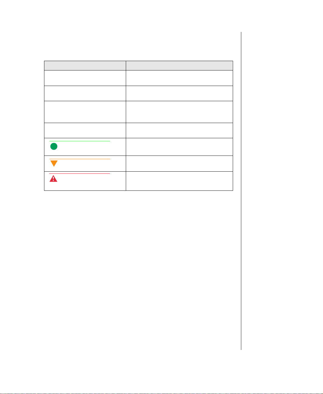
Con ventions Used in This Guide
Throughout this guide, you will see the following conventions:
Conve ntion Description
NTER
E
TRL+ALT+DEL
C
Setup
User’s Guide
Note:
Key board ke y names are printed in small
capitals.
A plus sign indicates t hat the keys must
be pressed simultaneously.
Commands to be entered, options to
select, and messages that appear on
your monitor ar e print ed in bold.
Names of publicat ions and files are
printed in italic.
A note informs you of spec ia l
circumstances.
Caution!
Warning!
A caution warns y ou o f possi ble damage
to equipment or loss of data.
A warni ng in d ic ate s th e pos sibility of
personal injury.
iii
Page 7

Safety Instructions
Warnin g!
Do not attempt to service
the syste m y our self e x cept
as ex pl aine d el sewhere in
the syste m do cumen ta tio n.
Adjust only those cont rols
covered in the instructions.
Openin g or r em o vi ng
covers marked “Do Not
Remove” may expose you
to dangerous electrical
voltages or other risks.
Ref er al l se rvic in g of t ho se
compartments to qualified
service personnel.
Observe the following safety instructions when using your system:
Follow all instructions marked on the system and in the
•
documentation.
When the system is turned off, a small amount of electrical current
•
still runs through the system. Always unplug the system from the
electrical outlet before cleaning the system or opening the cover.
(Follow the cleaning instructions on page 21.)
Do not use this product near water or a heat source, such as a
•
radiator or heat register.
Do not spill anything on or into the system. The best way to avoid
•
spills is to avoid eating and drinking near your system.
Make sure you set up the system on a stable work surface.
•
Openings in the system cabinet are provided for ventilation. Do not
•
block or cover these openings. Make sure you provide adequate
space (at least 12 inches) around the system for ventilation when
you set up your work area. Never insert objects of any kind into the
system ventilation slots.
Use the voltage setting for your area. The voltage selector switch is
•
set at the factory to the correct voltage.
iv E-5200 User’s Guide
This system is equipped with a 3-wire grounding plug (a plug with
•
a grounding pin). This plug will only fit into a grounded power
outlet. This is a safety feature. If you are unable to insert the plug
into the outlet, contact your electrician to replace the outlet.
Do not walk on the power cord or allow anything to rest on it.
•
If you use an extension cord with this system, make sure the total
•
ampere ratings on the products plugged into the extension cord do
not exceed the extension cord ampere rating. Also, the total ampere
requirements for all products plugged into the wall outlet must not
exceed 15 amperes.
Page 8

There is a danger of explosion if the CMOS (complementary
•
metal-oxide semiconductor) battery is replaced incorrectly.
Replace the battery with the same or equivalent type recommended
by the manufacturer. Dispose of used batteries according to the
manufacturer’s instructions.
Unplug the system from the wall outlet and refer servicing to
•
qualified personnel if:
The power cord or plug is damaged.
•
Liquid has been spilled into the system.
•
The system does not operate properly when the operating
•
instructions are followed.
The system was dropped or the cabinet is damaged.
•
The system’s performance changes.
•
v
Page 9

vi E-5200 User’s Guide
Page 10

Getting Started
Contents
Assembling Your System........................................ 2
Starting Your System .............................................. 4
Turning Off Your System ....................................... 7
Resetting Your System............................................ 8
Page 11

Assembling Your System
Before you unpack your system, prepare a safe working environment for
your computer by doing the following:
Provide a clean, flat, and stable surface for your computer. Allow at
•
least 12 inches at the rear of the chassis for cabling and air
circulation.
Note:
Keep the product carton
and packing material, in
case you need to send the
system out for repair. If you
retu rn y o ur sy s te m to th e
fa ctory i n di ff e r ent
packaging, your warranty
may b e vo id .
Obtain a grounded (three-prong) AC surge-protected power strip.
•
A surge-protected power strip helps protect against AC line spikes.
Protect your computer from extreme temperature and humidity. Do
•
not expose your computer to direct sunlight, heater ducts, or other
heat-generating objects.
Keep your system away from equipment that generates magnetic
•
fields, such as unshielded stereo speakers. Even a telephone placed
too close to the system may cause interference.
2 E-5200 U se r’s Gui de
Page 12
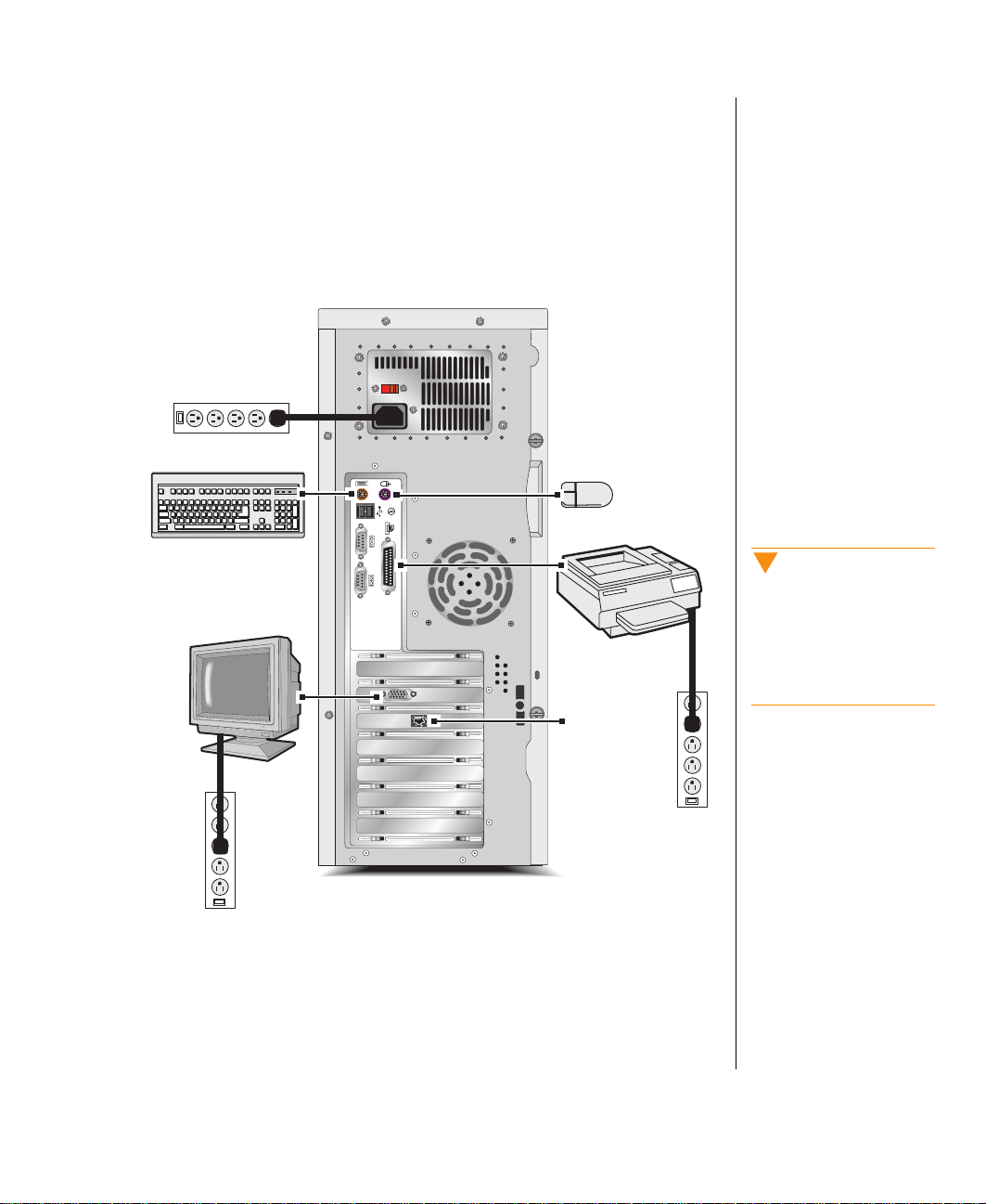
The following figure shows you how to connect basic peripherals to your
computer. Note that your system may not include all the items shown in the
figure.
Some connectors on the back of the system are colored to match the plugs
on peripherals that ship with your system. For more detailed information on
connecting peripherals, see “Rear Panel” on page 16.
Caution!
Make sure your computer
and peripherals are turned
off and un pl ug ge d f rom t he
power outlet when you
connect peripherals to the
system.
Network
Getting Started 3
Page 13
Note:
W
d
d
Plug the system into a wall
outlet that is easily
access ibl e . To remove al l
power from the system, you
need to unplug the system,
not just turn the system off
with the power button.
Starting Your System
Before you start your system for the first time,
Make sure all cables are firmly connected to the proper cable ports
•
on the rear panel of the system.
Make sure the system and monitor are plugged into an AC outlet or
•
power strip.
To start the system
Note:
ait unt il the st a rt-up
proc edur e is fin ishe d bef ore
loading any diskettes in the
isket te drive , or the syste m
ma y try to bo ot fro m th e
iskette drive.
If you have connected the system components to a power strip, make
1.
sure all the system components are turned off, and then turn on the
power strip.
Press the power button on the monitor to turn on the monitor.
2.
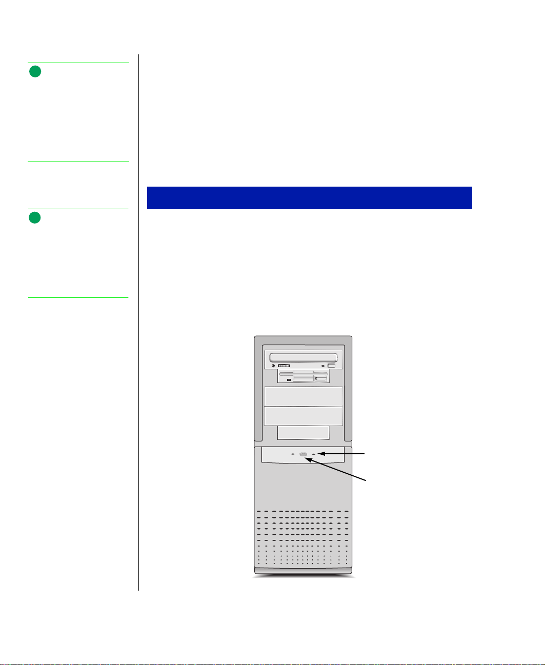
Press the power button on the computer to turn on the computer. The
3.
power LED (light-emitting diode) on the front panel is lit when the
computer’s power is on.
Power LED
Power button
4 E-5200 U se r’s Gui de
Page 14

Turn on any other components connected to the system, such as
Y
4.
speakers, a printer, or a scanner.
If nothing happens when you turn on the computer, recheck the power
5.
cables to see that they are securely plugged in and that your power strip
(if you are using one) is plugged in and turned on.
If you can hear the power supply fan whirring, but nothing appears on the
monitor, make sure the monitor is connected to the system, plugged into the
power strip or AC outlet, and turned on. You may also need to adjust the
brightness and contrast controls on the monitor.
For more troubleshooting information, see the “Troubleshooting” chapter in
the
Maintaining and Troubleshooting Your E-5200 System
guide
.
Understanding the Power-On Self-T est
When you turn on your computer, the POST (power-on self-test) routine
checks the system memory and components.
The system beeps or displays an error message if POST encounters any
errors. Write down the number of beeps that sound or the error message
that appears. See the “Troubleshooting” chapter of your
Troubleshooting Your E-5200 System
guide for a description of the beep
codes and error messages.
Maintaining and
Note:
ou can press TAB during
POST to see the test being
performed on the screen.
Press E
rema in in g me mory coun t.
to bypass the
SC
Getting Started 5
Page 15

Setting Up the Operating System
Your computer comes with the Windows NT® 4.0 operating system. The
first time you start your computer, the operating system takes a few minutes
to set up. Refer to your software documentation for specific instructions on
what to do after the system starts.
To complete the operating system setup
Note:
As you start Windows NT, if
you are connecting to a
network, have your TCP/IP
(transmission control
protocol/In ternet protocol)
information available.
After the system starts, the Start-up wizard opens. Click
1.
Next
continue.
In the dialog box, type your name and company in the appropriate text
2.
boxes. When you have finished entering the information, click
Continue following the instructions and selecting options in the Start-
3.
up wizard dialog boxes, clicking
to move through the dialog
Next
boxes until the wizard tells you to restart your computer.
Note that almost all the dialog boxes that open in the Start-up wizard
have a button that takes you back to previous dialog boxes in case you
need to change or correct the information you typed.
Restart your system. The setup is complete.
4.
to
Next
.
6 E-5200 U se r’s Gui de
Page 16

Turning Off Your System
Use the following steps every time you turn off your Windows NT system.
You may lose data if you do not follow the proper procedure.
To turn off your system
On the Taskbar, click
1.
Select
2.
Shut down the computer?
and then click
Start
Shut Down
.
Warnin g!
When you turn the
computer off by pressing
the power button, some
electric current still flows
through the system. Before
removing the system co ver
or connecting or removing
any peripherals, turn off the
system a nd th en u npl ug th e
power cord from the
electrical outlet.
Click
3.
When you see a message saying
4.
computer,
.
OK
It is now safe to turn off your
press your computer’s power button to turn off the
computer and then turn off the monitor and peripherals.
Getting Started 7
Page 17

Resetting Your System
If your computer does not respond to keyboard or mouse input, you may
need to reset the system.
To reset your system
1.
Press
TRL+ALT+DEL
C
. A window opens that enables you to close an
application that is not responding.
Click
2.
3.
T ask Manager,
click
End Task.
If your computer does not respond, press the power button on the
select the program that is not responding, and
computer. The computer turns off.
Wait a few seconds and then press and release the power button to turn
4.
on the computer.
Because you did not shut down your computer following the proper
procedure, you may be prompted to scan your hard drive for errors.
Follow the instructions on the screen.
8 E-5200 U se r’s Gui de
Page 18

Chapter 1:
System F eatures
Contents
System Features..................................................... 10
Front Panel............................................................. 14
Rear Panel.............................................................. 16
Page 19

System Features
The following features are standard to the system’s basic architecture.
AGP Video
An AGP (accelerated graphics port) video connector on the system board
and an AGP expansion card are standard features. AGP is a bus architecture
that increases video performance by routing video signals through a
dedicated graphics bus rather than sending video signals on the PCI bus.
BIOS
The BIOS (basic input/output system) is software that enables your
computer to communicate with peripheral devices (such as the keyboard,
mouse, and monitor) without using programs on the hard drive.
The battery in your computer maintains the BIOS settings in CMOS
memory even when the computer is turned off.
You can change the BIOS settings through the Setup program. Open Setup
by pressing F1 when you are prompted as your computer starts.
10 E-5200 User’s Guide
Cache Memory
Your system includes L2 (level 2) cache. Cache memory is located on the
processor. Cache reduces the average time required for the processor to get
the data it needs from the main memory by storing recently accessed data in
the cache.
Connectors
The standard I/O (input/output) connectors included with the computer are
keyboard port, mouse port, two serial ports, parallel port, two USB ports,
audio-out jack, AGP video port, and RJ-45 network connector.
Page 20

Drives
The standard configuration for your computer includes a 1.44-MB 3.5-inch
diskette drive, a hard drive, and a CD-ROM drive. You can install five
additional drives in the computer. Two IDE controllers and a diskette
controller are integrated into the system board. For instructions on installing
drives, see the “Installing and Removing Components” chapter in the
Maintaining and Troubleshooting Your E-5200 System
The first 2 GB (gigabytes) of the hard drive shipped with your Windows
NT system are partitioned as FAT (file allocation table)16. The rest of the
space on the drive is partitioned as NTFS (NT file system). Any other hard
drives shipped from the factory with your system are partitioned as NTFS.
FAT16 and NTFS are different methods the operating system uses to locate
files on a hard drive. NTFS supports large drive sizes, but NTFS partitions
cannot be viewed with MS-DOS® (Microsoft® disk operating system)
diagnostic utilities, like fdisk. See your Windows NT manual for more
information on NTFS.
guide
.
Expansion Sl ots
Expansion slots inside the computer enable you to install add-in cards, such
as a SCSI (small computer system interface) controller. Your computer
includes three 32-bit PCI (peripheral component interconnect) slots and two
8/16-bit ISA slot. For instructions on installing add-in cards, see the
“Installing and Removing Components” chapter in the
Troubleshooting Your E-5200 System
guide
.
Maintaining and
Intel 440 BX Ch ip Set
The Intel 440 BX chip set provides support for Pentium II processors. The
chip set’s Quad Port Acceleration improves bandwidth between the Pentium
II processor, the AGP, 100-Mhz SDRAM, and the PCI bus.
System Features 11
Page 21

Caution!
Do not mix registered and
unregistered DIMMs when
installing memory. See the
Maintaining and
Troubleshooting Your E5200 System
description of the type of
DIMMs yo u ca n inst a ll in
your sys t em.
guide for a
Manageabil ity
The status of your system’s hardware is monitored through the hardware
management ASIC (application specific integrated circuit) on the system
board. Monitored information includes voltage and chassis intrusion.
You can access the monitoring information through Intel® LANDesk®
Client Manager, which provides a quick system health indicator. For
additional information on LANDesk, see the “Troubleshooting” chapter of
the
Maintaining and Troubleshooting Your E-5200 Series System
guide
.
Memory
Your computer comes standard with ECC (error correcting code) SDRAM
(synchronous dynamic random access memory). You can install up to 1 GB
of memory in the four memory slots on the system board. You can fill the
slots with DIMMs of the sizes 64 MB, 128 MB, and 256 MB (when
available).
No jumper settings are required for the memory size or type because this
information is automatically detected by the BIOS. For information on
installing additional memory, see the “Installing and Removing
Components” chapter in the
guide
.
System
Maintaining and Troubleshooting Your E-5200
12 E-5200 User’s Guide
Networking
For easy connection to a network, a PCI-based 10/100 Mbps (megabits per
second) networking card is provided as a standard component of your
computer.
Processor
Your computer includes support for dual Intel Pentium® II processors. One
processor comes standard in the system.
Installing two processors enables your computer to take advantage of
multithreading on some graphics applications. These applications may run
faster with two processors than with one. See your software documentation
for more information.
Page 22

Both processors in your system should be of the same clock speed. For
information on removing and installing a processor, see the “Installing and
Removing Components” chapter in the
Your E-5200 System
guide.
Maintaining and Troubleshooting
System Features 13
Page 23
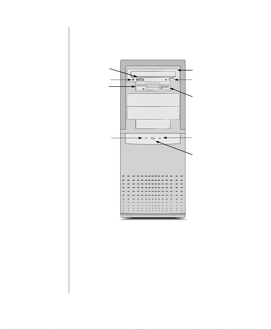
Front P anel
The front panel of your computer includes the following features:
CD-ROM
volume con t rol
CD-ROM drive
Audio-out jack
Diskette drive
Hard Drive LED
CD-ROM drive
eject button
Diskette drive
eject button
Power LED
Power button
14 E-5200 User’s Guide
Audio- Out Jack
You can connect headphones or powered speakers to the audio-out jack.
CD-ROM Drive
The high-speed CD-ROM drive enables you to play data or audio CDs.
Page 24

Diskette Drive
The diskette drive writes to and reads from 3.5-inch, 1.44 MB diskettes.
Hard Drive LED
The hard drive LED is lit when the hard drive is active.
Power Button
Push in the power button once to turn on the computer and push it in again
to turn off the computer.
Power LED
The power LED is lit when the computer is turned on.
System Features 15
Page 25
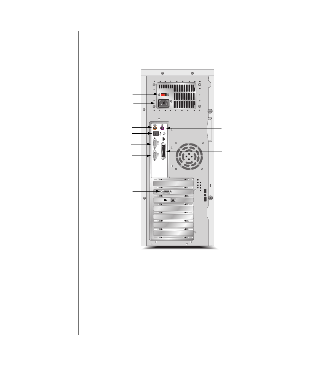
Rear Panel
The rear panel includes the following I/O ports, connectors, and switches:
Volt ag e se lect or
Power connector
Keyboard po rt
USB ports
Serial port 1
Serial port 2
Video port
RJ-45 Internet jack
Mouse port
Parallel port
Keyboard Port
Plug a PS/2 (Personal System/2)-compatible keyboard into this port.
16 E-5200 User’s Guide
Mouse Port
Plug a PS/2-compatible mouse into this port.
Page 26

Power Connect or
Plug the system power cord into this connector and to an AC outlet or
power strip.
Parallel (Printer ) Port
You can plug a printer or other parallel device into this port.
RJ-45 Network Jack
You can connect a cable to the RJ-45 network jack that connects the system
to the network of your choice.
Serial Ports
You can plug serial devices, such as MIDI (musical instrument digital
interface) devices, into these ports.
USB Ports
USB (universal serial bus) ports connect external Plug-and-Play devices
that are automatically configured when they are plugged into the system
through one of these ports. USB devices include keyboards, pointing
devices, monitors, and so on.
Vide o Port
Plug your monitor’s interface cable into the port. The video port provides
AGP capabilities.
Voltage Selector
The voltage selector is set to the correct voltage for your area, either 115 V
(volts) or 230 V, at the factory.
Caution!
Setting y o ur syste m t o the
wrong v ol tage ca n dam age
the system.
System Features 17
Page 27

18 E-5200 User’s Guide
Page 28

Maintaining and Cleaning Your System
Contents
Maintaining the Hard Drive .................................. 20
Cleaning Your System .......................................... 21
Page 29

Maintaining the Hard Drive
Hard drives need regular maintenance because running the system software
divides files, creates spaces between data, and otherwise decreases hard
drive performance. Windows NT provides the Check Disk utility to
maintain the hard drive. Check Disk enables you to check the drive for
errors, fix file system errors, and attempt to recover bad sectors on the
drive.
Use Check Disk from once a week to once a month, depending on how
often you use your computer. Also use Check Disk whenever you have any
hard drive problems.
To use Check Disk
Right-click
1.
In the Windows NT Explorer window, right-click the drive you want to
2.
and then click
Start
Explor e
.
check. You can only check one drive at a time.
Click
3.
Click the
4.
Click
5.
Check
6.
Properties
Tools
Check Now
Scan for an d at te mp t r e co ve ry o f ba d sec t or s
.
tab.
in the Error-checking dialog box.
to scan the
entire hard drive.
7.
Click
If the scan finds bad sectors, a screen message will notify
.
Start
you.
20 E-5200 User’s Guide
Page 30

Cleaning Your System
The following sections contain information about cleaning the parts of your
system.
Cleaning t he Mouse
If the mouse pointer on the screen moves erratically when you move the
mouse, the roller ball inside the mouse may be dirty.
To clean the mouse
Turn off the system and then disconnect the mouse cable from the
1.
mouse port.
Turn your mouse upside down and remove the roller ball cover.
2.
Cup your hand under the mouse and turn your mouse right-side up.
3.
The roller ball should drop into your hand. If it does not, gently shake
the mouse until the ball drops out of the socket.
Use adhesive tape to pick up any dust or lint on the surface of the ball
4.
and wipe away dirt or lint inside the ball socket. You can also blow into
the socket to remove dirt and lint. If foreign matter is trapped inside
the socket, use a cotton swab dipped in isopropyl alcohol to loosen it.
Let surfaces dry completely after cleaning.
Warnin g!
When y ou cl ea n t he
system, turn it off and
unplug the power cord. Be
careful not to drip liquid into
the compu t er and
peripherals when cleaning
the syst em.
Return the ball to the socket and replace the cover.
5.
Cleaning t he Keyboard
Occasionally, you should clean the keyboard to free it of dust and lint
particles trapped under the keys. The easiest way to do this is to blow
trapped dirt from under the keys using an aerosol can of air with a narrow,
straw-like extension.
Maintaining and Cleaning Your System 21
Page 31

If you spill liquid on the keyboard, turn off the computer and disconnect the
keyboard. Turn the keyboard upside down to let the liquid drain out and the
keyboard dry for a few days before trying to use the keyboard again. If the
keyboard does not work after draining, contact Technical Support.
Cleaning t he Monitor Screen
Use a soft cloth and window cleaner to clean the monitor screen. Squirt a
little cleaner on the cloth (never directly on the screen), and wipe the screen
with the cloth.
Cleaning t he Computer and Mo nitor Cases
Always turn off the computer and other peripherals before cleaning any
components.
Use a damp lint-free cloth to clean the computer case, monitor case,
keyboard, speakers, and other parts of your system. Avoid abrasive or
solvent cleaners because they can damage the finish on your components.
22 E-5200 User’s Guide
Page 32

Appendix
Contents
Acronyms and Abbreviations ............................... 24
Terms and Definitions........................................... 26
Page 33

Acron yms and Abbreviations
ASIC -
BIOS -
CMOS -
DIMM
DMI -
DRAM -
ECC
FAT -
GB -
IDE -
IRQ -
LAN -
LED -
MB -
Application specific integrated circuit
Basic input/output system
Complementary metal-oxide semiconductor
- Dual inline memory module
Desktop management interface
Dynamic random access memory
- Error correcting code
File allocation table
Gigabyte
Integrated drive electronics
Interrupt request line
Local area network
Light-emitting diode
Megabyte
24 E-5200 User’s Guide
Mbps -
MIDI -
Mhz -
MS-DOS -
NTFS -
POST -
PS/2 -
RAM -
ROM -
Megabits per second
Musical instrument digital interface
Megahertz
NT file system
Power-on self-test
Personal System/2
Random-access memory
Read-only memory
Microsoft disk operating system
Page 34

- Small computer system interface
SCSI
SDRAM -
TCP/IP -
- Volt
V
Synchronous dynamic random access memory
Transmission control protocol/Internet protocol
Appendix A 25
Page 35

T erms and Definitions
This list of terms should help you get acquainted with terms used in your
computer’s documentation and in your system software.
Applications
programs
BIOS -
independent of any operating system. It enables the computer to
communicate with the monitor, keyboard, and other peripheral devices
without using programs on the hard disk.
The BIOS on your computer is flash BIOS, which means that is has been
recorded on a memory chip that can be updated if needed.
To start your computer. A cold boot resets the computer and runs
Boot -
through all computer self-tests. A warm boot clears out computer memory
only.
Boot disk -
your computer. A boot disk can be a diskette, hard drive, or CD.
The basic unit of measure for computer memory. A character, such
Byte -
as a letter of the alphabet, uses one byte of memory. Each byte is made up
of eight bits. Computer memory is often measured in kilobytes (1,024
bytes) or megabytes (1,048,576 bytes).
Cache memory -
processor. Cache reduces the average time required for the processor to get
the data it needs from the main memory by storing recently accessed data in
the cache.
- Software installed on your system. Sometimes called
.
Basic input/output system. The BIOS is software that is
A disk containing operating system programs required to start
Cache is very fast memory that can be located in the
26 E-5200 User’s Guide
CMOS memory -
CMOS memory is memory that is retained even when the computer is
turned off. The Setup program settings and other parameters are maintained
in CMOS memory.
Default
made a choice yourself.
Disc -
- The option that the software or system uses when you have not
A compact disc (CD).
Complementary metal oxide semiconductor memory.
Page 36

The device used by the computer to store and retrieve information.
Disk -
Disk can refer to a diskette or a hard disk.
Diskette -
Hard drive
A removable disk, also called a floppy.
- The drive installed inside your system that stores all your
system and data files. Depending on its configuration, the computer may
have more than one hard drive. Each drive is assigned its own drive letter. If
you have only one drive, its drive letter is C, and it is often called “the C
drive.”
Input/output. Refers to devices, such as printers, whose purpose is to
I/O -
enter data into a computer or extract data from a computer. An I/O device is
accessed through an I/O address: a location in memory reserved for the
device to exchange information between itself and the rest of the computer.
Interrupt request line. The IRQ is a hardware line that a device uses
IRQ -
to signal the processor when the device needs the processor’s services. The
number of IRQs is limited by industry standards.
Operating system -
A program that supervises the computer’s operation,
including handling I/O, networking and connectivity, and device drivers.
- A sequence of information that directs the system to the file it needs.
Path
For example,
c:\windows\bubbles.bmp
your system. The c: tells the system it is on the C hard drive, the
tells the system it is in the windows folder, and
is the path to a graphics file on
\windows
bubbles.bmp
is the file.
A pixel is an individual dot in a graphic displayed on your computer.
Pixel -
Pixels are so close together that they look as though they are connected.
POST -
Power-on self-test. POST tests your computer’s components
whenever you turn on the computer.
Programs
- Software installed on your system. Programs are sometimes
called applications.
RAM -
Random access memory. RAM is the computer’s system memory.
You can write to and read from RAM. Information stored in RAM is
temporary and is erased when the computer is turned off.
Appendix A 27
Page 37

Refresh rate -
The refresh rate is the rate at which the image on the monitor
screen is rewritten to the screen. A fast refresh rate helps keep the image
from flickering.
Resolution -
The resolution is the sharpness or clarity of the image on the
monitor screen. Resolution is measured by the number of pixels the screen
can display. For example, a resolution of 800x600 means that the screen can
display 800 pixels in a row and can display 600 rows. The more pixels
displayed, the higher the resolution and the clearer the images.
ROM -
Read-only memory. Permanent computer memory dedicated to a
particular function. For example, the instructions for starting the computer
when you first turn on power are contained in ROM. You cannot write to
ROM.
28 E-5200 User’s Guide
Page 38

Computer Virus Notice
What is a virus?
A virus is a program written with malicious intent for the sole purpose of
creating havoc in a computer system. It attaches itself to executable files or
boot sectors, so it can replicate and spread. Some viruses may only cause
your system to beep or display messages or images on the screen. Other
viruses are highly destructive and corrupt or erase the contents of your files
or diskettes. To be safe, never assume any virus is harmless.
What types of viruses are known?
Viruses are identified by how they infect computer systems.
•
Program viruses
.exe, .ovl, .drv, .sys, and .bin.
•
Boot viruses
or partition table.
•
Multipartite viruses
infect executable program files such as .com,
attach themselves to a boot record, master boot, FAT,
are both program and boot infectors.
How does a virus spread and contaminate?
There are many ways a virus can spread and infect your system. However, a
virus is inactive until the infected program is executed, or a boot record is
read. Thereafter, the virus loads itself into system memory and begins to
copy and spread itself.
Diskettes used in a contaminated system can get infected and, in turn,
transfer the virus when used in another system. A virus can also spread via
programs downloaded from bulletin boards or the Internet. Remember that
viruses cannot appear all by themselves. They have to be written, then
spread through direct contact with executable programs or boot sectors.
29
Page 39

What can you do to protect your system?
Awareness is the key. You need to learn about the existence of viruses, how
they spread, and what to do to protect your system by reducing the
likelihood of virus contamination. The following may help:
Obtain an anti-virus program and make it a habit to scan the
•
system regularly. These programs may be purchased from a local
software store or obtained via shareware on the Internet or online
service providers such as CompuServe, Prodigy, AOL, or
DeltaNet.
Make backup copies of all files and write-protect the diskettes.
•
Obtain all software from reputable sources and always scan new
•
software for any viruses before installing files.
If you suspect your system has been infected, you must find and remove the
viruses immediately using an anti-virus program. Next, reboot your system
as follows: shut the system down, then turn it off for at least 15 seconds
before turning it back on. This is the only way to ensure the virus does not
remain in your system RAM.
30 E-5200 User’s Gu ide
What do we do to prevent virus contamination?
We stand by the integrity of our products. Our staff takes every precaution
to ensure our files are free from viruses. These precautions include the
following:
We use McAfee VirusScan, a leading anti-virus software that
•
detects and removes over 95% of known viruses and provides
comprehensive protection including local and network drives, CDROMs, floppies, boot sectors, and partition tables. VirusScan also
provides advanced protection against unknown viruses. We
continuously update and use the most current version of McAfee
VirusScan on all of our products.
All master diskettes are write-protected and scanned at least twice
•
before release.
Page 40

Sample production diskettes are periodically scanned as an
•
additional quality check.
All incoming products such as systems to repair, vendor diskettes,
•
hard drives, and trade-show units are scanned for viruses.
All systems are given a final test before shipping.
•
Unfortunately, today’s technology makes the creation of newer viruses
possible, some of which can elude even the best scanners available. Hence,
there is no absolute guarantee of virus immunity on any product. If you
think you have received an infected product from us, please contact
Technical Support. Our staff will assist you in correcting the problem.
31
Page 41

Regulatory Compliance Statements
American Users
Caution!
The Federal
Communications
Commissi on w arns u sers
that changes or
modifications to the unit not
expressly approved by the
party responsible for
compliance could void the
user’s authority to operate
the equi pme nt .
This device has been tested and found to comply with the limits for a Class
B digital device, pursuant to Part 15 of the FCC rules. These limits are
designed to provide reasonable protection against harmful interference in a
residential installation. This equipment generates, uses, and can radiate
radio frequency energy and, if not installed and used in accordance with the
instructions, may cause harmful interference to radio or television
reception. However, there is no guarantee that interference will not occur in
a particular installation. If this equipment does cause interference to radio
and television reception, which can be determined by turning the equipment
off and on, the user is encouraged to try to correct the interference by one or
more of the following measures:
Reorient or relocate the receiving antenna.
•
Increase the separation between the equipment and receiver.
•
Connect the equipment into an outlet on a circuit different from
•
that to which the receiver is connected.
Consult the dealer or an experienced radio/TV technician for help.
•
Use shielded I/O cables when operating this equipment.
•
Accessories: This equipment has been tested and found to comply with the
limits of a Class B digital device. The accessories associated with this
equipment are as follows:
Canadian Users:
32 E-5200 User’s Gu ide
Shielded video cable
•
Shielded power cord
•
These accessories are required to be used in order to ensure compliance
with FCC rules.
This digital apparatus does not exceed the Class B limits for radio noise
emissions from digital apparatus as set out in the radio interference
regulations of Industry Canada.
Page 42
Le présent appareil numérique n’émet pas de bruits radioélectriques
dépassant les limites applicables aux appareils numériques de Classe B
prescrites dans le règlement sur le brouillage radioélectrique édicté par
Industrie Canada.
Attention!
Couper le courant avant l’entr etien.
This Information Technology Equipment has been tested and found to
comply with the following European directives:
[i]EMC Directive 89/336/EEC amending Directives 92/31/EEC & 93/68/
EEC as per:
-EN 50081-1:1992 according to
EN 55022:1995 Class B
EN 61000-3-2:1995 or EN 60555-2:1986
EN 61000-3-3: 1995
-EN50082-1:1992 according to
EN 61000-4-2:1995 or IEC 801-2:1984
ENV 50140:1994 or IEC 801-3:1984
EN 61000-4-4:1988 or IEC 801-4:1998
[ii]Low Voltage Directive (Safety) 73/23/EEC as per EN 60950:1992, A1,
A2, and A3
This is a Class B product based on the standard of the Voluntary Control
Council for Interference by Information Technology Equipment (VCCI). If
this is used near a radio or television receiver in a domestic environment, it
may cause radio interference. Install and use the equipment according to the
instruction manual.
Europe an Use r s:
Japane se Use rs:
33
Page 43

Australian and New
Zealand Users:
This device has been tested and found to comply with the limits for a Class
B digital device, pursuant to the Australian/New Zealand standard AS/NZS
3548 set out by the Spectrum Management Agency.
Caution!
Disconn ec t p o wer be f or e servic ing .
Warning!
There is a danger of explosion if the battery is incorr ectly replaced. Replace the CMOS
battery with the same or equivalent type recommended by the manufacturer. D ispose of
used batteries according to the manufacturer’s instructions.
34 E-5200 User’s Gu ide
Page 44

Index
A
Abbreviations 24
AGP (accelerated graphics port)
Assembling your system
Audio-out jack
14
10
2
B
BIOS (basic input/output system) 10
C
Cache memory 10
Cases, cleaning
CD-ROM drive
Check Disk utility
Cleaning your system
Closing programs with Ctrl+Atl+Del
CMOS (complementary metal oxide
Connecting peripherals
22
14
20
21
semiconductor) memory
3
10
D
Definitions of terms 26
Disk drive
Disk drive connector
Drives, standard
15
11
11
E
Error messages 5
Expansion slots
11
I
I/O (input/output) connectors 10
IDE (integrated drive electronics)
connectors
Intel 440 BX chipset
11
K
Keyboard
cleaning
port
22
16
L
LANDesk 12
M
Manual conventions iii
8
Memory
cache
10
installing
Monitor
adjusting
cleaning
Monitoring your system
Mouse
cleaning
port
12
5
22
21
16
N
Network connector 17
11
12
F
Features of your system 10
Front panel
14
H
Hard drive
15
20
11
maintaining
partitioning
Hard drive LED (light-emitting diode)
O
Operating system, setup 6
P
Parallel port 17
Peripherals, connecting
POST (power-on self-test)
Power
4,
button
connector
LED (light-emitting diode)
15
17
3
5
4,
15
35
Page 45

Processor
benefits of dual processors
standard
12
R
Rear panel 16
Resetting your system
RJ-45 connector
8
17
S
Safety iv, 2
Serial ports
Setting up your operating system
Shut-down procedures
Starting your system
System
17
assembling
cleaning
features
manageability
memory
power
resetting
starting
turning off
21
10
12
iv
8
4
7
7
4
2
12
T
12
Turning off your system 7
U
Understanding POST (power-on self-
test)
5
USB (universal serial bus) ports
17
V
Video
connector
port
6
standard
Voltage selector
10
17
10
17
W
Windows NT
Check Disk utility
setup
6
shut-down procedures
Working environment, preparing
20
7
2
36 E-5200 User’s Guide
Page 46

MAN SYS US E5200 USR GDE R0 6/98
8502954
 Loading...