

Page 1
E1400 Mid Tower
System Manual
Page 2

Contents
Preface..............................................................v
Conventionsusedinthismanual ....................................... v
Gettingadditionalinformation ..........................................vi
1 System Features ................................................1
Easytoservicechassis...............................................1
Standardfeatures ...................................................1
Frontpanel ........................................................2
Rear panel . . . . . . . . . . . .............................................4
Insidethecomputer ..................................................6
Systemboard ......................................................7
Risercard .........................................................8
Front ..........................................................8
Back ..........................................................9
2 System Setup ..................................................11
Settingupyoursystem ..............................................11
Startingyoursystem ................................................12
UnderstandingthePower-OnSelf-Test ..............................13
Settinguptheoperatingsystem ....................................13
Turningoffyoursystem..............................................14
Resettingyoursystem...............................................15
3 Case Access ...................................................17
Staticelectricityprecautions ..........................................17
Openingthecase ..................................................19
Removingthesidepanels ........................................19
Closingthecase ...................................................23
Replacingthesidepanels ........................................23
4 Replacing and Adding Drives ..................................25
Aboutreplacingdrives...............................................25
Releasingthedrivecage.............................................26
Reinsertingthedrivecage ...........................................28
Replacingthediskettedrive ..........................................29
Addingaseconddiskettedrive........................................31
ReplacingtheCDdrive ..............................................33
Addingasecond5.25-inchdevice .....................................35
i
Page 3

Replacingtheharddrive .............................................38
Adding an additional hard drive . . . . . . . . . . ..............................41
5 System Components ............................................45
Addingorreplacingmemory ..........................................45
Adding an expansion card . ...........................................48
ReplacingtheAGPcard..............................................51
Replacingthebattery ................................................52
Replacingthepowersupply ...........................................54
Replacingthesystemboard...........................................56
Replacingtheprocessor..............................................61
6 Using the BIOS Setup Utility ....................................65
AbouttheBIOSSetuputility...........................................65
UpdatingtheBIOS ..................................................67
Settingthesystemboardjumpers ......................................69
Recoverymode .................................................69
7 Managing Your System .........................................71
Protectingagainstpowersourceproblems ...............................71
Surgesuppressors ...............................................71
Lineconditioners ................................................72
Uninterruptiblepowersupplies......................................72
Maintainingandmanagingyourharddrive ...............................73
Harddrivemaintenanceutilities.....................................73
Harddrivemanagementpractices ...................................75
Systemintegrity ....................................................78
Protectingagainstviruses .........................................78
CheckingsystemhealthwithLANDesk ...............................79
Systemrecovery ....................................................80
Creatingastartupdiskette .........................................80
Keepingarecordofsystemconfiguration .............................80
UsingyourSystemRestorationCD..................................81
System power management ...........................................82
Aboutsoft-off ...................................................82
UsingSuspendinWindows95 .....................................82
UsingStandbyinWindows98 ......................................84
8 Cleaning Your System ..........................................87
Cleaningthemouse .................................................87
Cleaningthekeyboard ...............................................88
Cleaningthemonitorscreen ..........................................88
ii
Page 4

Cleaningthecomputerandmonitorcases ...............................88
9 Troubleshooting ................................................89
Introduction .......................................................89
Troubleshootingchecklist ............................................90
Verifyingyourconfiguration .......................................90
Troubleshootingguidelines ........................................90
CD/DVDdriveproblems .............................................91
Harddriveproblems ................................................93
Memory/processorproblems ..........................................94
Modemproblems...................................................95
Peripheral/adapterproblems ..........................................96
Printerproblems ...................................................98
Systemproblems...................................................99
Videoproblems ...................................................101
Errormessages ...................................................104
10 Safety, Regulatory, and Notices ...............................109
A Specifications .................................................121
Index..............................................................123
iii
Page 5

iv
Page 6

Preface
Conventions used in this manual
Throughout this manual, you will see the following conventions:
Convention Description
ENTER Keyboard key names are printed in small capitals.
TRL+ALT+DEL Aplussignmeanstopressthekeysatthesametime.
C
Setup Commands to be entered, options to select, and messages that
appear on your monitor are printed in bold.
User’s Guide Names of publications are printed in italic.
Important A note labeled important informs you of special
circumstances.
Caution A caution warns you of possible damage to equipment or
loss of data.
Warning A warning indicates the possibility of personal injury.
Conventions used in this manual v
Page 7

Getting additional information
Log on to the Gateway Support Center at www.gateway.com/support to find
information about your system or other Gateway products. Some types of
information you can access are:
Hardware driver and program updates
Technical tips
Service agreement information
Technical documents and component information
Frequently asked questions (FAQ)
Documentation for peripherals or optional components
Online access to technical support
vi
Page 8

System Features
Easy to service chassis
The E1400 Mid Tower has many features that let you easily access the inside
of your system to add and remove components, such as hard drives, memory,
and processors.
Standard features
The following features are standard in the E1400 Mid Tower system:
Intel® Celeron™ and Pentium III™ (FC-PGA 370) processors with 128K
and 256K of integrated L2 cache, respectively
Two DIMM sockets that support up to 512 megabytes (MB) of
Synchronous Dynamic Random Access Memory (SDRAM)
Intel 810 chipset
Integrated Heceta IV Hardware Management Application Specific
Integrated Circuit (ASIC)
1
Five PCI slots
One 1.44 MB 3.5-inch diskette drive, one CD drive, and one hard drive
Keyboard port, mouse port, serial port, parallel port, video port, two
Universal Serial Bus (USB) ports, RJ-45 Ethernet port, and audio line-out
and audio line-in ports
200-watt power supply
Easy to service chassis 1
Page 9

Front panel
The front panel contains following features:
Audio-out port
CD volume control
Diskette drive
Hard drive LED
Power button
Audio-out port connects headphones or powered speakers that let you listen
to an audio CD (directly from the CD drive).
CD drive
CD eject button
Diskette eject button
Reset button
Power LED
Right panel
release button
CD drive plays data or audio CDs.
CD eject button ejects a CD from the CD drive.
CD volume control controls the volume of an audio CD.
Diskette drive writes to and reads from 3.5-inch, 1.44 MB diskettes.
Diskette eject button ejects diskettes from the diskette drive.
Hard drive LED lights when the hard drive is active.
Power button turns the computer on and off.
2 System Features
Page 10

Power LED lights when the computer is turned on. The green light indicates
your computer is using full power. The amber light indicates your computer
is in power conservation mode.
Reset button restarts a system that becomes non-responsive.
Right panel release button lets you easily remove the right panel to access
the internal components of your system.
Front panel 3
Page 11
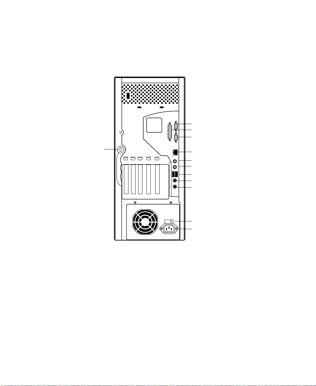
Rear panel
The Mid Tower rear panel includes the following Input/Output (I/O) ports,
connectors, and switches:
Video port
Parallel port
Serial port
Kensington lock slot
RJ-45LANconnector
Mouse port
Keyboard port
USB ports
Audio line-out
Audio line-in
Voltage selector
Power connector
Audio Line-out, and Line-in jacks connect audio devices such as speakers,
tape players, and microphones.
Kensington lock slot permits the use of a cable lock to secure the system.
Keyboard port connects a Personal System/2
®
(PS/2) compatible keyboard.
Mouse port connects a PS/2 compatible mouse.
Parallel port connects a printer or other parallel device.
4 System Features
Page 12

Power Connector connects the computer power cord. The other end of the
power cord plugs into an AC outlet or power strip.
RJ-45 LAN connector connects a network cable.
Serial port connects serial devices, such as a musical instrument digital
interface (MIDI) device.
USB ports connect external Plug-and-Play devices, such as keyboards and
pointing devices, that are automatically configured when they are plugged
into the computer through one of these ports.
Video port connects the monitor interface cable.
Voltage selector sets the voltage for your area, either 115V (US standard) or
230V.
Rear panel 5
Page 13

Inside the computer
The following illustration shows locations of various system components:
G
F
E
A
BB
C
A System board
B Riser card
C Power supply release lever
D Power supply
E Hard drive (hard drive shown here in top bay: bay location may
vary)
F Diskette drive
G CD drive
6 System Features
D
Page 14

System board
F
E
D
A
C
A I/O (input/output) connectors
B Configuration jumper (J6C1)
C Battery
D DIMM slots
E Processor
F Processor fan connector
System board 7
Page 15

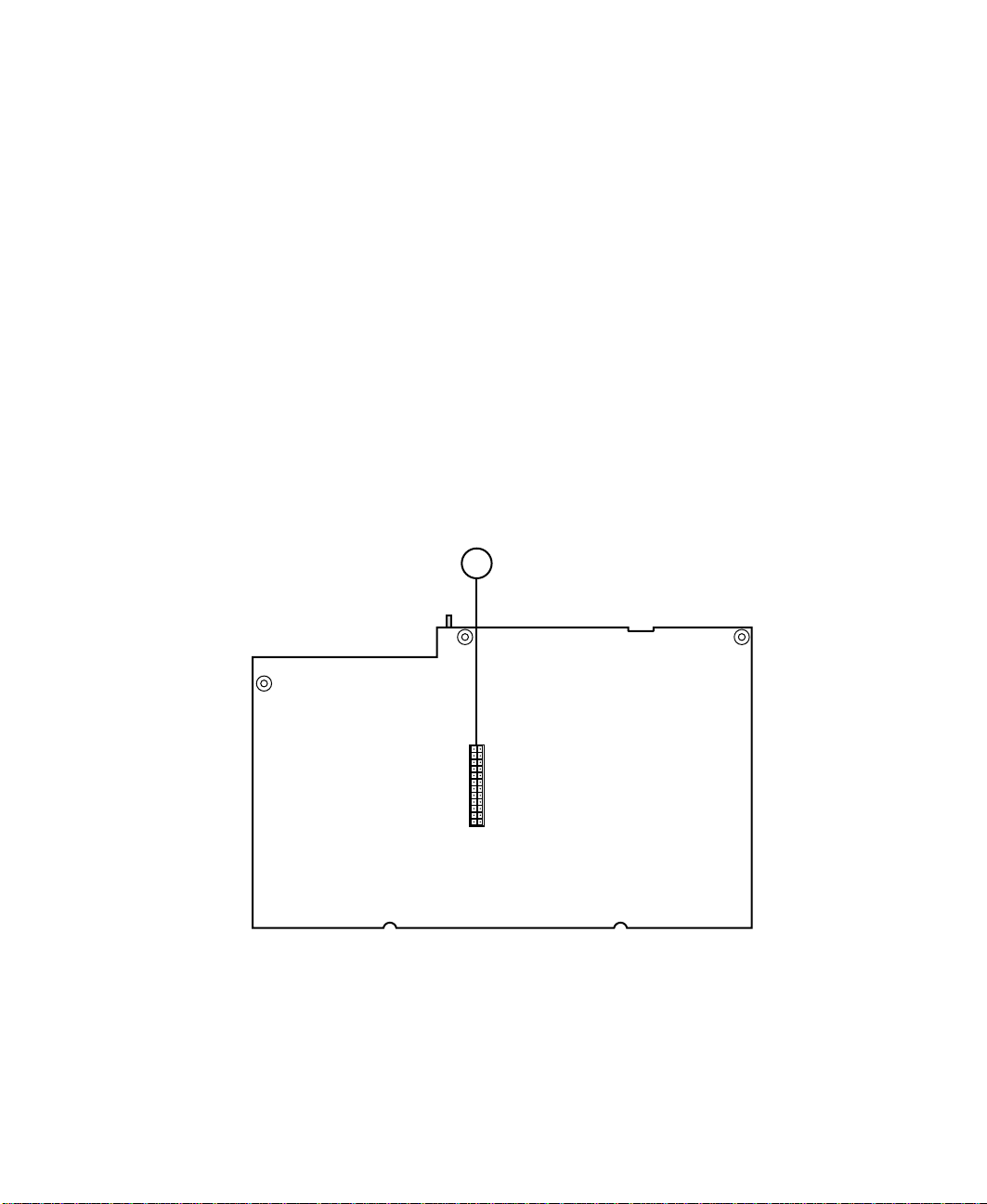
Riser card
The riser card is mounted to the chassis by three screws at the top. The riser
card includes a chassis intrusion switch to alert you if the computer cover is
removed. It also includes five PCI connectors for add-on cards.
Front
B C DE
AF
Q
P
O
N
M
L
K
A Secondary IDE connector
B CD/diskette drive power connector
C Wake-on LAN connector (WOL)
D Net Alert connector (AOL)
E Ring-in connector
F System board connectors
G System chassis fan connector
8 System Features
HIJ
G
Page 16
Back
PCI slots (5)
H
I Chassis intrusion switch
J Hard drive power connector
K Primary IDE connector
L Remote lock/unlock
M Chassis fan connector
N Front panel connector
O SCSI LED connector
P CD/DVD audio connector
Q Diskette drive connector
A
A Power supply connector
Riser card 9
Page 17

10 System Features
Page 18

System Setup
Setting up your system
Follow the instructions on the poster that came with your system for assembly
instructions. You can prepare a safer working environment before assembling
your system by following the guidelines listed below.
Provide a clean, flat, stable surface for your system. Allow at least
12 inches at the rear of the computer for cabling and air circulation.
Obtain a grounded (three-prong) AC surge-protected power strip. A
surge-protected power strip helps protect against AC line spikes.
Protect your system from extreme temperature and humidity. Do not
expose your system to direct sunlight, heater ducts, or other
heat-generating objects.
Keep your computer away from equipment that generates magnetic
fields, such as unshielded stereo speakers. Even a telephone placed too
close to the computer may cause interference.
Plug the computer into a wall outlet or power strip that is easily
accessible. When you turn off the computer with the power button, some
electricity still flows through the computer. To remove all power from
the computer, you need to unplug it.
2
Important Keep the product cartonand packing material, in caseyou
need to send the system out for repair. If you return your
system to the factory in different packaging, your warranty
may be void.
Setting up your system 11
Page 19

Starting your system
Before you start your system for the first time:
Refer to the safety information beginning on page 109.
Make sure the voltage selector switch on the back of the computer is set
to the correct voltage for your area. This switch is set at the factory to
the correct voltage (see “Rear panel” on page 4 for voltage selector switch
location).
Make sure all cables are firmly connected to the proper ports on the rear
panel of the computer.
Caution Make sure your computer and peripherals are turned off
and unplugged from the power outlet when you connect
peripherals to the computer.
Make sure the computer and monitor are plugged into an AC outlet or
power strip.
To start the system:
1 If you have connected the system components to a power strip, make
sure all the system components are turned off, then turn on the power
strip.
2 Turn on the monitor by pressing the power button.
3 Turn on the computer by pressing the power button. The power
light-emitting diode (LED) on the front panel is lit when the power is on.
4 Turn on any other components connected to the computer, such as
speakers, a printer, or a scanner.
If nothing happens when you turn on the system:
Recheck the power cables to see that they are securely plugged in
and that your power strip (if you are using one) is plugged in and
turned on.
Make sure the monitor is connected to the computer, plugged into
the power strip or AC outlet, and turned on. You may also need
to adjust the brightness and contrast controls on the monitor.
12 System Setup
Page 20

Wait until the startup procedure is finished before loading a diskette in the
diskette drive, or the computer may search the diskette for startup
information.
Understanding the Power-OnSelf-Test
When you turn on your computer, the Power-On Self-Test (POST) routine
checks the system memory and components. To see this information on the
screen, press T
count.
The system displays an error message if POST finds any problems. Write down
the error message that appears.
AB during POST. Press ESC to bypass the remaining memory
Setting up the operating system
The first time you start your computer, the operating system takes a few
minutes to set up.
Refer to your software documentation for specific questions.
To complete the operating system setup:
1 After the computer starts, the start-up wizard opens. Continue by clicking
Next.
2 Type the requested information in the appropriate text boxes. When you
have finished entering the information, continue by clicking
Next.
3 Continue following the instructions and selecting options in the start-up
wizard dialog boxes, clicking
the wizard tells you to restart your computer.
If you need to return to the previous dialog box to change any of your
entries, click
Back.
Next to move through the dialog boxes until
4 Restart your system. The setup is complete.
Starting your system 13
Page 21

Turning off yoursystem
Every time you turn off your system, shut down the operating system first.
You may lose data if you do not follow the proper procedure.
To turn off your system in Windows 95:
1 On the taskbar, click Start.
2 Click Shut Down.
3 Select Shut down the computer?
4 Click Yes. The computer turns off.
5 Turn off the monitor and peripherals.
To turn off your system in Windows NT or Windows 98:
1 Click Start, then select Shut Down (Windows 98) or Shut down the
computer?
2 Select Shut Down.
3 Click OK. The computer turns off. If you see a message saying It is now
safe to turn off your computer
by pressing the power button.
(Windows NT).
(Windows NT only), turn off the computer
4 Turn off the monitor and peripherals.
Warning When you turn the computer off by pressing the power
Important You can use the power button to turn off your system if
14 System Setup
button, some electric current still flows through the
computer. Before opening the computer case or
connecting or removing any peripherals, turn off the
computer and then unplug the power cord and modem
cord (if installed).
the system does not respondto commands. However,you
must hold the power button in for 4 seconds to turn it off
(Windows 95 and Windows 98 only).
Page 22

Resetting yoursystem
If your computer does not respond to keyboard or mouse input, you may have
to close any programs that are not responding. If closing unresponsive
programs does not restore your computer to normal operation, you may have
to reset the system.
To reset your system in Windows 95 or Windows 98:
1 Press CTRL+ALT+DEL. A window opens that lets you close a program that
is not responding.
2 Highlight a program that displays a “not responding” message and click
End Task. Close the program by following any additional screen prompts.
3 If the computer does not respond, restart the computer by pressing the
reset button.
4 After displaying some of the startup screens, a message appears asking if
you would like to run ScanDisk.
5 Run ScanDisk by pressing any key. Follow the on-screen instructions.
When the checks are finished, Windows starts.
To reset your system in Windows NT:
1 Press CTRL+ALT+DEL. A window opens that lets you to close a program
that is not responding.
2 Click Task Manager, then select the program that is not responding.
3 Close the program by clicking End Task.
4 If the computer does not respond, press the reset button to restart the
computer.
As a part of the regular startup process, a program to check the disk status
automatically runs. When the checks are finished, Windows starts.
Resetting your system 15
Page 23

16 System Setup
Page 24

Case Access
Static electricity precautions
Static electricity can permanently damage electronic components in your
computer. When opening your computer case, always perform the following
procedure.
Caution Prevent electrostatic damage to your computer by
followingstatic electricity precautions every time you open
your computer case.
To avoid static electricity discharge:
1 Wear a grounding wrist strap (available at most electronics stores).
2 Turn off the computer power.
3 Discharge any static electricity by touching a bare metal surface on the
back of the case.
4 Unplug all power cords from AC outlets and disconnect the modem cable
(if installed).
3
Static electricity precautions 17
Page 25

Follow these precautions to avoid electrostatic damage to your system
components:
Avoid static-causing surfaces such as plastic and packing foam in your
work area.
Remove the parts from their antistatic bags only when you are ready to
use them. Do not lay parts on the outside of antistatic bags since only
the inside of the bags provides antistatic protection.
Always hold cards by their edges and their metal mounting brackets.
Avoid touching components on the cards and the edge connectors that
connect to expansion slots.
Never slide cards or other parts over any surface.
Warning Avoid exposure to dangerous electrical voltages and
moving parts by turning off your computer. Unplug the
power cord and modem cord before removing the
computer cover.
18 Case Access
Page 26

Opening the case
The case has two removable side panels. Both panels are screwless, meaning
you do not have to remove any screws to take off the panels.
The right panel is removed by pressing a button located on the front panel.
The L-shaped panel covers both the right side and top of the chassis. The left
panel is removed by sliding a tab located on the top of the chassis.
Removing the sidepanels
To remove the right panel:
1 Because the components inside your computer are extremely sensitive to
static electricity, make sure to observe the “Static electricity precautions”
on page 17.
2 Turn off the computer, disconnect the power cord, modem cord (if
installed), and all external peripheral devices.
Opening the case 19
Page 27

3 Push the release button located in the lower right-hand corner of the
front bezel. The bottom portion of the right panel unlatches from the
chassis.
Rightpanel
20 Case Access
2
1
Right panel release button
Page 28

Lift up on the right panel, then lift the panel up and away from the
4
chassis.
Right panel
Opening the case 21
Page 29

To remove the left panel:
1 Remove the right panel. (See “Removing the side panels” on page 19 for
instructions.)
2 Slide the left panel release tab toward the rear of the chassis. This
unlatches the left panel from the chassis.
Left panel
release tab
1
2
3 Grasp the left panel, then lift the panel up away from the chassis.
22 Case Access
Left panel
Page 30

Closing the case
Replace the cover as soon as you finish installing or removing components
so that dust and dirt (which could damage the computer) do not collect inside
the computer.
Replacing the side panels
To replace the left panel:
1 Align the tabs at the bottom of the panel with the tab holes at the base
of the chassis.
2 Insert the tabs into the tab holes.
3 Push the panel towards the chassis until it locks into place.
Closing the case 23
Page 31

To replace the right panel:
1 Align the tabs at the top of the panel with the tab holes at the top of
the chassis.
Tab holes
2 Insert the tabs into the tab holes.
3 Push the bottom of the right panel towards the chassis until the tabs
engage the tab holes at the bottom of the chassis. The chassis
automatically locks into place.
4 Reconnect the power cord and all other cords you removed.
24 Case Access
Page 32

Replacing and Adding Drives
About replacing drives
The standard configuration for your computer includes a 5.25-inch IDE CD
drive, a 3.5-inch IDE hard drive, and a 3.5-inch diskette drive.
Your computer contains the following drive bays:
Two 3.5-inch drive bays that can be accessed from outside the computer.
Two 5.25-inch drive bays that can be accessed from outside the computer.
Three 3.5-inch drive bays that can only be accessed from inside the
computer.
As you prepare to install drives, keep the following in mind:
If you remove a drive, place it in an antistatic bag.
Before you install a drive, see the drive’s documentation for information
on configuring the drive, setting any jumpers on the drive, and attaching
cables to the drive.
4
If you are installing a drive that uses an add-in controller, install the
add-in card before you install the drive.
IDE hard drives can be configured as single, master, or slave. IDE CD
drives can be configured as master or slave. Configure the drives by using
the drive-select jumpers located on the drives.
About replacing drives 25
Page 33

If only one drive is attached to a controller cable, configure the drive as
single if it is a hard drive or master if it is a CD drive. If two drives of
any type are attached to the cable, configure one as master and one as
slave.
You may need to configure the drives you install using the BIOS Setup
utility program. Press F1 at start up to access the BIOS Setup utility
program.
Releasing the drive cage
You do not have to remove any screws to release the drive cage. The drive
cage is secured in the chassis by a drive cage release button. Once the release
button is pressed, you use the handle at the top of the cage to slide the cage
forward from the chassis. Slide the drive cage forward to add or replace
memory or to remove the cover filler to add an additional CD or diskette drive.
To release the drive cage:
1 Turn off the computer, disconnect the power cord, modem cord (if
installed), and all external peripheral devices.
2 Remove the right panel. (See “Removing the side panels” on page 19 and
observe the “Static electricity precautions” on page 17.)
26 Replacing and Adding Drives
Page 34

Using one hand, grasp the drive cage handle located above the drive cage.
3
Using your other hand, press the drive cage release button while pulling
the drive cage toward the front of the chassis.
Release button
forward locking hole
Drive cage
release button
Drive cage
handle
4 Slide the drive cage forward until the drive cage release button snaps into
the forward locking hole.
Releasing the drive cage 27
Page 35

Reinserting the drive cage
You can easily slide the drive cage back into the chassis.
To reinsert the drive cage:
1 With one hand, press the drive cage release button, then push the drive
cage back into the chassis with the other hand until the release button
snaps into the rear locking hole.
Release button
rear locking hole
Drive cage
release button
2 Replace the right panel. (See “Replacing the side panels” on page 23 for
instructions.)
3 Reconnect the power cord and all other cords you removed, then turn
on the system.
28 Replacing and Adding Drives
Page 36

Replacing the diskette drive
The 3.5-inch diskette drive is attached to the drive cage with a drive locking
tab. The drive cage is secured in the chassis with a drive cage release button.
You do not have to remove any screws to release the drive cage or remove
the diskette drive.
To replace a 3.5-inch diskette drive:
1 Turn off the computer, disconnect the power cord, modem cord (if
installed), and all external peripheral devices.
2 Remove the right panel. (See “Removing the side panels” on page 19 and
observe the “Static electricity precautions” on page 17.)
3 Disconnect the power and data cables from the back of the diskette drive.
4 Release the drive locking tab from the diskette drive bay by turning the
knob on the tab counter-clockwise to the unlock position, then remove
the tab from the drive cage.
Drive locking tab
Locking tab holes
Replacing the diskette drive 29
Page 37

5 From the rear of the drive cage, push the diskette drive toward the front
of the chassis and through the front bezel.
Diskette
drive
6 Place the new drive into the drive cage. Make sure the threaded holes
on the diskette drive align with the locking tab holes on the drive cage.
7 Replace the drive locking tab.
8 Connect the power and data cables to the drive.
9 Replace the right panel. (See “Replacing the side panels” on page 23 for
instructions.)
10 Reconnect the power cord and all other cords you removed, then turn
on the system.
30 Replacing and Adding Drives
Page 38

Adding a second diskette drive
You can add a second 3.5-inch diskette drive. You do not have to use any
screws to add the diskette drive, but you need to purchase a diskette drive
connector cable that supports two devices.
To add a second diskette drive:
1 Turn off the computer, disconnect the power cord, modem cord (if
installed), and all external peripheral devices.
2 Remove the right panel. (See “Removing the side panels” on page 19 and
observe the “Static electricity precautions” on page 17.)
3 Release the drive cage and slide it forward in the chassis until the release
button snaps into the forward locking hole.
4 Release the drive locking tab from the empty diskette drive bay by turning
the knob on the tab counter-clockwise to the unlock position, then
remove the tab from the drive cage.
Drive locking tab
Adding a second diskette drive 31
Page 39

5 Remove the filler panel on the front bezel by squeezing the two tabs on
the left side of the filler panel. The filler panel then ejects.
Drive cage
Filler
panel
6 Place the new diskette drive into the drive cage. Make sure the threaded
holes on the diskette drive align with the locking tab holes on the drive
cage.
7 Replace the drive locking tab.
8 Connect the power and data cables to the drive.
9 Push the release button in and slide the drive cage back into the chassis
until the button snaps into the rear locking hole.
10 Replace the right panel.
11 Reconnect the power cord and all other cords you removed, then turn
on the system.
32 Replacing and Adding Drives
Page 40

Replacing the CD drive
The CD drive is attached to the drive cage by a drive locking tab. You do not
have to remove any screws to remove or install a CD drive.
To replace the CD drive:
1 Turn off the computer, disconnect the power cord, modem cord (if
installed), and all external peripheral devices.
2 Remove the right panel. (See “Removing the side panels” on page 19 and
observe the “Static electricity precautions” on page 17.)
3 Disconnect the power, data, and audio cables from the back of the drive.
4 Release the drive locking tab from the drive bay by turning the knob on
the tab counter-clockwise to the unlock position, then remove the tab
from the drive cage.
Drive locking tab
Replacing the CD drive 33
Page 41

5 From the rear of the drive cage, push the drive toward the front of the
chassis and through the front bezel.
CD drive
6 Set any jumpers on the new drive. (See the drive documentation for more
information.)
7 Place the new CD drive into the drive cage. Make sure the threaded holes
on the drive align with the locking tab holes on the drive cage.
8 Replace the drive locking tab.
9 Connect the power, data, and audio cables to the drive.
10 Replace the right panel (see “Replacing the side panels” on page 23).
11 Reconnect the power cord and all other cords you removed, then turn
on the system.
34 Replacing and Adding Drives
Page 42

Adding a second 5.25-inch device
You can add a second 5.25-inch device, such as a CD-RW or CD/DVD drive.
You do not have to use any screws to add the device.
1 Turn off the computer, disconnect the power cord, modem cord (if
installed), and all external peripheral devices.
2 Remove the right panel. (See “Removing the side panels” on page 19 and
observe the “Static electricity precautions” on page 17.)
3 Release the drive cage and slide it forward in the chassis until the release
button snaps into the forward locking hole.
4 Release the drive locking tab from the empty drive bay by turning the
knob on the tab counter-clockwise to the unlock position, then remove
the tab from the drive cage.
Drive
locking tab
Adding a second 5.25-inch device 35
Page 43

5 Remove the filler panel on the front bezel by squeezing the two tabs on
the left side of the filler panel. The filler panel then ejects.
Filler panel
6 Set any jumpers on the new drive. (See the drive documentation for more
information.)
36 Replacing and Adding Drives
Page 44

Place the new drive into the drive cage. Make sure the threaded holes
7
on the drive align with the locking tab holes on the drive cage.
5.25-inch
device
8 Replace the drive locking tab.
9 Connect the power and data cables to the drive.
10 Push the release button in and slide the drive cage back into the chassis
until the button snaps into the rear locking hole.
11 Replace the right panel.
12 Reconnect the power cord and all other cords you removed, then turn
on the system.
Adding a second 5.25-inch device 37
Page 45
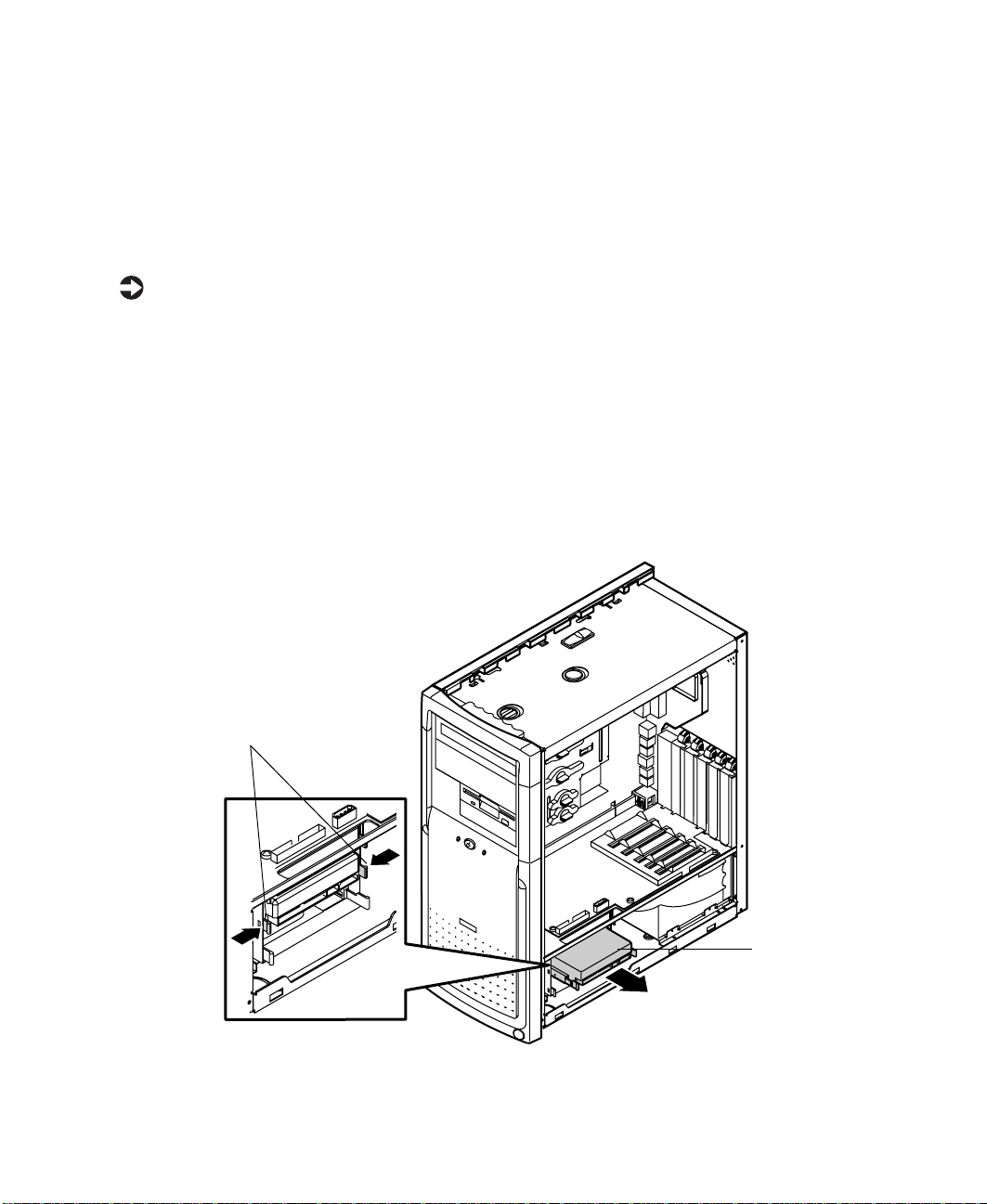
Replacing the hard drive
The 3.5-inch hard drive is located in a metal tray that slides in and out of
the hard drive cage. The tray has a spring so you can expand the tray to insert
a drive. When you release the sides of the tray it will contract back together
and secure the drive.
To replace the 3.5-inch hard drive:
1 Turn off the computer, disconnect the power cord, modem cord (if
installed), and all external peripheral devices.
2 Remove the right panel. (See “Removing the side panels” on page 19 and
observe the “Static electricity precautions” on page 17.)
3 Disconnect the power and data cables from the hard drive.
4 The metal tray that holds the hard drive is secured by a set of hard drive
tray release tabs. Remove the tray by squeezing both release tabs inward,
then slide the hard drive tray out of the drive cage.
Hard drive tray
release tabs
38 Replacing and Adding Drives
Harddrive
Page 46

Pull on the rail to expand the tray, then remove the drive from the tray.
5
6 Set any jumpers on the new drive. (See the drive documentation for more
information.)
7 Align the threaded holes on the side of the hard drive with the metal
points on the tray, then press the drive against the side rail.
Metal points
Side rail
8 Expand the tray until it fits the size of your drive, then lower the drive
into the tray. Release the tray so it can contract to secure the drive.
Replacing the hard drive 39
Page 47

9 Align the drive tray rails with the side channels in the hard drive cage,
then slide the drive tray into the hard drive cage.
Drive tray rails
Harddriv e
10 Push the drive tray into the drive cage until the release tabs snap into
place.
11 Connect the power and data cables to the drive.
12 Replace the right panel. (See “Replacing the side panels” on page 23 for
instructions.)
13 Reconnect the power cord and all other cords you removed, then turn
on the system.
40 Replacing and Adding Drives
Page 48

Adding an additional hard drive
The E1400 Mid Tower hard drive cage can hold up to three 3.5-inch hard
drives.
Important The IDE controller supports two IDE devices. If you want
to install a third hard drive you need to install an add-in
controller card.
To add an additional hard drive:
1 Turn off the computer, disconnect the power cord, modem cord (if
installed), and all external peripheral devices.
2 Remove the right panel. (See “Removing the side panels” on page 19 and
observe the “Static electricity precautions” on page 17.)
3 Choose the bay in the drive cage where you want to install the additional
hard drive. The metal tray that will the hold the hard drive is secured
by a set of hard drive tray release tabs.
Adding an additional hard drive 41
Page 49

4 Remove the tray by squeezing both release tabs inward, then slide the
hard drive tray out of the drive cage.
Drive tray release tabs
Hard drive
cage
5 Set any jumpers on the new drive. (See the drive documentation for more
information.)
6 Align the threaded holes on the side of the hard drive with the metal
points on the tray.
Metal points
Side rail
42 Replacing and Adding Drives
Page 50

Expand the tray until it fits the size of your drive, then lower the drive
7
into the tray. Release the tray so it can contract to secure the drive.
8 Align the drive tray rails with the side channels in the hard drive cage,
then slide the drive tray into the hard drive cage.
Drive tray rails
Harddriv e
Adding an additional hard drive 43
Page 51

9 Push the drive tray into the drive cage until the release tabs snap into
place.
10 Connect the power and data cables to the drive.
11 Replace the right panel. (See “Replacing the side panels” on page 23 for
instructions.)
12 Reconnect the power cord and all other cords you removed, then turn
on the system.
44 Replacing and Adding Drives
Page 52

System Components
Adding or replacing memory
The Synchronous Dynamic Random Access Memory (SDRAM) Dual Inline
Memory Modules (DIMMs) supported by your system board conform to the
following standards:
16 MB, 32 MB, 64 MB, 128 MB, and 256 MB
Non-ECC (64-bit) memory
Single- or double-sided configurations
512 MB maximum system memory
The system board contains two DIMM sockets. You can fill the sockets with
16-MB, 32-MB, 64-MB, 128-MB, or 256-MB DIMMs in any combination to
expand the SDRAM up to 512 MB.
If your processor has a 66-MHz front side bus (FSB), you can use 66-MHz or
100-MHz SDRAM. If your processor has a 100-MHz FSB, you should use only
100-MHz SDRAM.
5
No jumper settings are required for the memory size or type because the BIOS
automatically detects this information.
Adding or replacing memory 45
Page 53

To install DIMMs:
1 Turn off the computer, disconnect the power cord, and disconnect the
modem cord, if your computer has a modem.
2 Open the case by following the instructions on page 19, observing the
static electricity precautions on page 17.
3 Remove the drive cage so that you can access the DIMM sockets. (See
page 26 for instructions on removing the drive cage.)
4 Pull open the socket clamps on each side of the DIMM socket and lift
the DIMM out of the socket.
Caution Nevertry to remove a DIMM withoutreleasing the clamps.
You may break the socket, causing serious damage.
46 System Components
Page 54

Insert the DIMM into the socket and align the two bottom notches in
5
the DIMM with the two notches in the DIMM socket.
6 Gently press the DIMM into the socket until the plastic socket clamps
on each side of the socket snap into the notches on the side of the DIMM.
7 Replace the drive tray. (See “Reinserting the drive cage” on page 28 for
instructions.)
8 Close the case. (See “Closing the case” on page 23 for instructions.)
9 Reconnect the cords you removed, then turn on the computer.
Adding or replacing memory 47
Page 55

Adding an expansion card
The E1400 Mid Tower chassis has five expansion slots for PCI cards. The riser
card has five PCI connectors.
A card alignment guide attached to the riser card helps you align PCI cards
in the slots.
To add a PCI expansion card:
1 Set any jumpers and switches on the card (see the card documentation
for instructions).
2 Turn off the computer, disconnect the power cord, modem cord (if
installed), and all external peripheral devices.
3 Open the right panel (see “Removing the side panels” on page 19 for
more information, and observe the “Static electricity precautions” on
page 17.)
4 Locate an available slot.
48 System Components
Page 56

Slot
cover
From inside the computer, press the slot cover clamp down and toward
5
the back of the chassis, then lift the slot cover up and out of the chassis.
Slot cover
clamp
Plastic tab
Card alignment guideCard alignment guide
Adding an expansion card 49
Page 57

6 Insert the edge of the expansion card into the slot on the riser card and
press firmly to seat the card. If the plastic tabs on the card alignment
guide interfere with the proper seating of the card, the tabs may be
snapped off to accommodate the installation the card.
Expansion
card
Plastic tab
7 Close the slot cover clamp to secure the card.
8 Connect any cables to the card (see the card documentation for proper
jumper settings and cable orientation).
9 Replace the right panel. (See “Replacing the side panels” on page 23 for
more information.)
50 System Components
Page 58

Replacing the AGP card
Observe the following instructions for replacing the Accelerated Graphics Port
(AGP) card.
To replace the AGP card:
1 Turn off the computer, disconnect the power cord, modem cord (if
installed), and all external peripheral devices.
2 Remove the right panel. (See “Removing the side panels” on page 19 and
observe the “Static electricity precautions” on page 17.)
3 Using a Phillips screwdriver, remove the screw that secures the AGP card
to the rear panel, then pull out the card.
AGP card
4 Install the new AGP card, making sure the card is firmly seated on the
system board, then secure the AGP card to the rear panel with the screw.
5 Reconnect the monitor cable, then turn on the system and all peripheral
devices.
Replacing the AGP card 51
Page 59

Replacing the battery
The battery (3.3V) provides power for the system real-time clock and CMOS
RAM, which holds the system configuration information.
If your battery is failing you may notice your system clock slowing down and
giving you the incorrect time. If so, open the BIOS Setup utility and write
down all the values in the BIOS Setup utility screens before replacing the
battery. Replacing the battery resets the BIOS Setup utility to its default values.
Caution There is a danger of explosion if the battery is incorrectly
replaced. Replace the battery only with the s ame or
equivalent type recommended by the manufacturer.
Dispose of used batteries according to the manufacturer’s
instructions.
To replace the battery:
1 Restart the computer and start the BIOS Setup utility by pressing F1 when
you are prompted to do so.
2 Write down the CMOS values from the Main Setup utility screens so you
can reenter them after you replace the battery. (For more information,
see “About the BIOS Setup utility” on page 65.)
3 Turn off the computer, disconnect the power cord, modem cord (if
installed), and all external peripheral devices.
4 Remove the right panel. (See “Removing the side panels” on page 19 and
observe the “Static electricity precautions” on page 17.)
5 Locate the battery on the system board (see “System board” on page 7).
The battery is circular and has the positive pole mark (+) on the top.
6 Using your fingers to grasp the sides of the battery, carefully remove the
battery from its socket.
52 System Components
Positive pole symbol
Page 60

Press the new battery in the socket with the positive pole up. Make sure
7
you have pressed the battery down far enough for it to contact the base
of the socket.
8 Replace the right side panel. (See “Replacing the side panels” on page 23
for more information.)
9 Reconnect the power cord and all other cords you removed, then turn
on the system.
10 Using the data you recorded in Step 2, enter the BIOS Setup utility, then
make sure that the system configuration is correct. If the CMOS data is
not correct, change the information in the setup screens as necessary.
Replacing the battery 53
Page 61

Replacing the powersupply
Observe the following instructions for removing the power supply and
installing a new one. Your power supply can be removed without
disconnecting power supply cables or removing screws.
To replace the power supply:
1 Turn off the computer, disconnect the power cord, modem cord (if
installed), and all external peripheral devices.
2 Remove the right panel. (See “Removing the side panels” on page 19 and
observe the “Static electricity precautions” on page 17.)
3 Pull the power supply release lever away from the chassis. This releases
the power supply from its connector and moves it out from the back of
the chassis.
Power supply
release lever
4 From the rear side of the chassis, pull the power supply out and away
from the chassis.
54 System Components
Power
supply
Page 62

Make sure that the voltage switch on the back of the new power supply
5
is set to the correct voltage for your area.
6 Insert the new power supply and slide it into the chassis until it engages
the connector.
7 Push the release level all the way in to secure the power supply.
8 Replace the right side panel. (See “Replacing the side panels” on page 23
for more information.)
9 Reconnect the power cord and all other cords you removed, then turn
on the system.
If the system does not start, make sure that you installed the power supply
correctly and that the voltage connector on the back of the power supply is
correctly set.
Replacing the power supply 55
Page 63

Replacing the system board
The system board is installed on a system board tray assembly. To remove the
system board, you must first remove the system board tray assembly from the
chassis. The tray assembly can be removed from the chassis without tools.
The I/O shield is attached to the system board tray assembly and does not
have to be removed when you remove the system board.
To remove the system board tray assembly:
1 Turn off the computer, disconnect the power cord, modem cord (if
installed), and all external peripheral devices.
2 Remove the right and left side panels. (See “Removing the side panels”
on page 19 for instructions. Also observe the “Static electricity
precautions” on page 17.)
3 Locate the system board release handle at the top of the system board
tray assembly. Lift the handle up to disconnect the system board from
the riser card and unlatch the tray assembly from the chassis.
System board
release handle
System board
tray assembly
56 System Components
Page 64

Grasp the handle, lower the tray assembly slightly, then support the
4
bottom or back of the tray assembly with your other hand and pull it
away from the chassis.
Warning Do not release the tray assembly until you have lifted it
off the hinges and can safely place it on a work surface.
The hinges are designedto make it easy for you to lift the
tray assembly away from the chassis, but the hinges can
be damaged if the tray assembly is allowed to hang open
or is lowered too far.
Replacing the system board 57
Page 65

To replace the system board:
1 Remove or disconnect the following devices from the system board:
Processor. (See “Replacing the processor” on page 61 for
instructions.)
DIMMs. (See “Adding or replacing memory” on page 45 for
instructions.)
AGP graphics card. (See “Replacing the AGP card” on page 51.)
Devices from the old system board that are not included with the
new board, such as processor retention brackets.
2 Remove the four screws that attach the system board to the system board
tray assembly, then lift out the system board.
3 Remove the new system board from its packing material.
System
board
Rear I/O
shield
System board
tray assembly
4 Install the new board onto the system board tray assembly, carefully
aligning the ports and connectors with the holes on the rear I/O shield.
5 Reinstall the four screws to secure the board to the tray assembly.
58 System Components
Page 66

To replace the system board tray assembly:
1 Align the two hinges on the sides of the system board tray over the pins
on the chassis.
Hinges
Hinge pins
2 Move the release handle on the tray assembly to an outward position.
Replacing the system board 59
Page 67

3 Push the tray assembly toward the chassis until the three tabs at the top
of the tray assembly are seated in the corresponding slots on the chassis.
Tab slots
Tabs
4 Push the handle in and slide the tray assembly downward until it locks
the tray in place.
5 Turn the chassis around and press down on the top edge of the system
board to make sure that it is firmly seated in the riser card slot.
6 Replace or reconnect the following devices:
Processor. (See “Replacing the processor” on page 61.)
AGP graphics card. (See “Replacing the AGP card” on page 51.)
Peripheral devices attached to the rear-panel I/O connectors.
Devices from the old system board that are not included with the
new board. (See “System board” on page 7 for device locations.)
7 Replace the left and right panels. (See “Replacing the side panels” on
page 23 for instructions.)
8 Reconnect the power cord and all other cords you removed, then turn
on the system.
60 System Components
Page 68

Replacing the processor
Your system board currently supports the Intel Celeron and Pentium III
(FC-PGA 370) processors. See the Gateway Web site at www.gateway.com for
updates on processor speeds supported by your system.
When replacing a processor, order a processor upgrade kit. The kit includes
the processor and a heat sink..
Warning It is critical that a heat sink be installed on the processor
to provide sufficient cooling.
To replace the processor:
1 Turn off the computer, disconnect the power cord, and disconnect the
modem cord, if your computer has a modem.
2 Open the case by following the instructions on page 19, observing the
static electricity precautions on page 17.
3 Remove the heat sink:
a Disconnect the fan cable from the fan connector on the system
board. (See “System board” on page 7 for the location of the fan
connector.)
b The heat sink is attached to the processor socket by a metal clip.
Unhook the clip from the tab on the processor socket by pressing
down on the clip and then pulling out on the clip.
Metal clip
Tabs
Replacing the processor 61
Page 69

c Lift the heat sink at an angle and unhook the clip from the other
tab. Lift the heat sink off the processor.
4 Remove the processor:
a Open the locking lever on the processor socket by moving the lever
slightly out to the side and then lifting it up 90 degrees.
Processor
Pin 1
Locking
lever
b Lift the old processor straight up and out of the socket.
5 Install the new processor:
a Hold the new processor over the empty processor socket and verify
that pin 1 on both the processor and the socket are aligned. Pin
1 is near the cut out corner.
b Gently place the new processor into the socket.
c Secure the processor by lowering the locking lever until the lever
latches into place. The processor will slip into place without
pressure when aligned correctly.
62 System Components
Page 70

Replace the heat sink:
6
a Hook the metal clip on the heat sink to the tabs on the processor
socket. Make sure the heat sink is level with the processor and the
metal clips are securely attached.
Caution It is very important that the heat sink makes direct contact
withthe processor or else it will not cool correctly,resulting
in processor failure.
b Connect the heat sink fan cable to the fan connector on the system
board.
7 Close the case. (See “Closing the case” on page 23 for instructions.)
8 Reconnect the cords you removed, then turn on the computer.
You do not have to manually adjust the processor speeds. Your system BIOS
automatically detects the processor speed for you.
Replacing the processor 63
Page 71

64 System Components
Page 72

Using the BIOS Setup Utility
About the BIOS Setup utility
The computer’s BIOS has a built-in setup utility that lets you configure several
basic system characteristics. The settings are stored in battery-backed RAM and
are retained even when the power is off.
Enter the BIOS Setup utility by restarting the computer, then pressing F1 when
prompted during the startup process. The Main BIOS Setup utility screen
(which may not look exactly like the screen shown below) opens.
BIOS Setup Utility
Main Advanced Security Power Boot Exit
Item Specific Help
BIOS Version:
Processor Type:
Processor Speed:
Cache RAM:
Total Memory:
xx
Intel Pentium III
600 MHz
256 KB
96 MB
Select the default
language used by the
BIOS.
6
Bank 0:
Bank 1:
Language:
System Time:
System Date:
RDRAM
RDRAM
[English (US)]
[xx:xx:xx]
[xx/xx/xxxx]
←→
=
Select Menu
↑↓
=
Select Item
Enter Select>Sub-Menu
F9 Setup Default
F10 Save and Exit
ESC Exit
F1 Help
About the BIOS Setup utility 65
Page 73

As you select items on the Main menu, or in submenus, you will see specific
information related to the current selection in the Item Specific Help box.
Refer to the Help box for information about the menu options.
The command bar shows the keystrokes necessary to access help, navigate
through the menus, and perform other functions.
F1 opens the Help screen, providing general help for using the BIOS Setup
utility.
The ↑
=
(up arrow) and ↓ (down arrow) keys select items in the menu.
The ← (left arrow) and → (right arrow) keys move you between the
menus.
ENTER either moves you to a submenu screen when a selected item is
preceded by > or activates a selected field.
ESC closes the screen you are in and returns you to the previous screen
or exits you from the BIOS Setup utility.
F9 opens a screen that lets you return all values to their default settings.
F10 opens a screen that lets you save all parameters and then exit the
BIOS Setup utility.
The main screen has the following menu selections at the top of the screen:
Main gives you access to basic information and settings related to your
system hardware and configuration.
Advanced gives you access to information and settings for system
resources, hardware, and system configuration.
Security gives you access to settings related to system access passwords.
Power gives you access to information and settings for power
management features.
Boot gives you access to information and settings for boot features and
boot sequences.
Exit gives you access to options for exiting the BIOS Setup utility.
Refer to the Help box on the right side of the BIOS Setup screens for
information about menu items.
66 Using the BIOS Setup Utility
Page 74

Updating the BIOS
If you need a new version of the BIOS, you can download the BIOS update
from technical support on the Gateway Web site (www.gateway.com) and
install the new version from a diskette.
To update the BIOS you need to perform the following tasks in sequence:
Create a bootable diskette
Note the current BIOS settings
Create the BIOS update diskette
Update the BIOS
Restore the BIOS settings
To create a bootable diskette:
1 Enter DOS and type the following at the DOS prompt: format a: /s
1 Put a blank diskette in the diskette drive, then press ENTER.
2 Follow the instructions on the screen.
To note the current BIOS settings:
1 Remove the bootable diskette and restart your computer.
2 Enter BIOS Setup by pressing F1 when prompted during startup.
3 Write down the settings for each of the fields. (At the end of the BIOS
update process, you will reset the fields back to the values you recorded.)
4 Exit the BIOS Setup utility.
To create the BIOS update diskette:
1 Log on to the Internet.
2 Download the correct BIOS file from the technical support area of
www.gateway.com.
3 Decompress the contents of the BIOS file you downloaded and copy the
contents onto the bootable diskette.
Updating the BIOS 67
Page 75

To update the BIOS:
1 Place the bootable diskette containing the BIOS files into drive A:, then
restart the computer. The BIOS Setup utility starts.
2 Press ENTER. The Main menu opens.
3 Select Update Flash Memory From a File, then press ENTER.
4 Select Update System BIOS.
5 Press TAB to select the file name, then press ENTER. The computer warns
you that the BIOS is about to be changed and asks you to confirm the
BIOS version.
6 Press ENTER. The BIOS files are loaded.
7 Once the BIOS files have been loaded, remove the diskette from
drive A:, then press E
NTER when prompted to restart the computer.
8 As the computer starts up, verify that the number of the BIOS version
reported on the screen is the number of the new BIOS you downloaded
from the Internet.
To restore the BIOS settings:
1 Enter BIOS Setup by pressing F1 when prompted during startup.
2 Once in BIOS Setup, press F9 to load the BIOS Setup utility default
settings.
3 Select any BIOS fields you want to change by using the ↑
↓ (down arrow) keys. Press ENTER, then reenter the values you wrote down
at the beginning of this process.
68 Using the BIOS Setup Utility
=
(up arrow) and
Page 76

Setting the system board jumpers
The J6C1 configuration jumper on the system board lets you clear passwords
and recover the BIOS. (See the figure on page 7 for the location of the jumper.)
The table below shows the settings required to perform those tasks. Make sure
you turn off the computer and unplug the power cord before moving the
jumper.
Caution Moving the jumper while the computer power is on can
damage your computer. Always turn off the computer and
unplug the power cord from the computerbeforechanging
the jumper.
J6C1 Mode Jumper
Normal
Configure
Recovery
Recovery mode
If you are trying to update the BIOS and have a problem such as a power
outage, the update may not be successful. You can then attempt to recover
the BIOS by setting the J6C1 jumper.
When you are attempting to recover the BIOS, no image appears on your
monitor.
Setting
Pins 1-2
Pins 2-3
No jumper
Action When Set
Normal operation
Adds a Maintenance menu to
BIOSSetup utilitywithoptionsto
clear passwords
Causes computer to attempt
BIOS update or recovery from
diskette
Setting the system board jumpers 69
Page 77

To recover the BIOS:
1 Turn off the computer, disconnect the power cord, then disconnect the
modem cord, if your computer has a modem.
2 Open the case. (See “Opening the case” on page 19 and observe the
“Static electricity precautions” on page 17.)
3 Remove the jumper from the J6C1 jumper (See “System board” on page 7
for location) and set it aside. You will need it in a later step.
4 Close the case (See “Closing the case” on page 23 for instructions.), then
reconnect the power cords.
5 Place the bootable diskette containing the BIOS files into drive A:, then
turn on the computer.
At the start of the BIOS recovery process, the computer beeps once. The
recovery process may take a few minutes.
6 When you hear two beeps, the BIOS has successfully recovered. Remove
the diskette from drive A:, turn off the computer, then disconnect the
power cord.
If you do not hear two beeps, the BIOS recovery was not successful. See
the troubleshooting section below for further information.
7 Open the case again (See “Opening the case” on page 19 and observe the
“Static electricity precautions” on page 17.)
8 Place the jumper back on pins 1-2 on the J6C1 jumper.
9 Close the case, reconnect the cords, then turn on the computer.
10 Enter BIOS Setup utility by pressing F1 when prompted during startup.
Once in BIOS Setup utility, press F9. The default settings for the BIOS
Setup utility are loaded.
11 Select a BIOS field that you want to change by using the ↑
↓ (down arrow) keys. Press ENTER, then reenter the values you wrote
and
down at the beginning of the BIOS update process.
Troubleshooting: If the BIOS recovery was unsuccessful the computer will
beep continuously or will not beep at all. If the computer beeps continuously,
make sure all the BIOS files you downloaded are on your diskette. If the
computer does not beep at all and the diskette drive light stays on, make sure
your BIOS update diskette is a bootable diskette. If you continue to have
problems, contact Client Care or your system administrator.
70 Using the BIOS Setup Utility
=
(up arrow)
Page 78

Managing Your System
Protecting against power source problems
Surge suppressors, line conditioners, and uninterruptible power supplies (UPS)
can help protect your system against power source problems.
Surge suppressors
During a power surge, the voltage level of electricity coming into your system
can increase far above normal for a few milliseconds. Data may be lost or the
system may be damaged. To protect against power surges, use a surge
suppressor. The surge suppressor absorbs voltage surges and prevents them
from reaching your system.
A surge suppressor plugs directly into an electrical outlet. Your computer,
monitor, and other devices are connected to the surge suppressor.
If you have a modem, make sure your surge suppressor has jacks for the
telephone and modem cables. Power surges can pass through telephone wires
as well as electrical wires.
7
Protecting against power source problems 71
Page 79

When purchasing a surge suppressor:
Make sure the surge suppressor meets the appropriate product safety
certification for your location, such as Underwriters Laboratories (UL).
Check the maximum amount of voltage the suppressor allows to pass
through the line. The lower the voltage that the suppressor allows to pass
through, the better the protection for your system.
Check the energy absorption, or dissipation, rating. The higher the energy
absorption rating, the better the protection for your system.
Check for line-conditioner capabilities. A line conditioner smooths out
some of the normal line noise (small voltage fluctuations) of an electrical
supply.
Line conditioners
A line conditioner protects your system from the small daily fluctuations in
voltage from an electrical supply. Most systems can handle this variation, or
line noise, without problems. However, some electrical sources include more
line noise than normal. Line noise can also be a problem if your system is
located near, or shares a circuit with, a device that causes electromagnetic
interference, such as a television or a motor.
Some surge suppressors and uninterruptible power supplies include simple
line-conditioning capabilities.
Uninterruptible powersupplies
You may lose data during a total power failure. A standby Uninterruptible
Power Supply (UPS) uses a battery to keep your system running during a power
failure. The UPS enables you to shut down your system normally, but not run
the system for an extended time.
If you purchase a standby UPS, make sure the UPS includes surge suppression
and line-conditioning features.
72 Managing Your System
Page 80

Maintaining and managing your hard drive
Regular maintenance can keep your hard drive operating efficiently, and good
file management can keep your system free of unwanted files while making
important files secure and easier to find.
Hard drive maintenance utilities
By regularly using the following utilities, you can help maintain the
performance of your hard drive:
ScanDisk (Windows 95 and Windows 98)
Check Disk (Windows NT)
Disk Defragmenter (Windows 95 and Windows 98)
Using ScanDisk in Windows 95and Windows 98
Bad sectors are parts of a hard drive or diskette that will not hold data. A lost
allocation unit is a group of sectors that has lost its place in the table that
the operating system uses to locate files. ScanDisk checks the hard drive for
bad sectors or lost allocation units and lets you fix them.
Use ScanDisk from once a week to once a month, depending on how often
you use your system. Also use ScanDisk if you have any hard drive problems.
To use ScanDisk:
1 Double-click the My Computer icon on the desktop. The My Computer
window opens.
2 Click the drive you want to check.
3 Select File, then Properties. The drive’s properties window opens.
4 Click the Tools tab.
5 At Error-checking status, click Check Now. The ScanDisk window opens.
6 Select the options you want for checking the drive.
7 If you want ScanDisk to check more than one drive, press and hold SHIFT,
then click on the additional drives in the list of drives to check.
Maintaining and managing your hard drive 73
Page 81

8 Click Start. ScanDisk checks the drive for errors.
9 Follow any instructions on screen for completing the scan.
Using Check Disk inWindows NT
Bad sectors are parts of a hard drive or diskette that will not hold data. A lost
allocation unit is a group of sectors that has lost its place in the table that
the operating system uses to locate files. Check Disk checks the hard drive
for bad sectors or lost allocation units and lets you fix them.
Use Check Disk from once a week to once a month, depending on how often
you use your system. Also use Check Disk if you have any hard drive problems.
To use Check Disk:
1 Double-click the My Computer icon on the desktop. The My Computer
window opens.
2 Click the drive you want to check.
3 Select File, then Properties. The drive properties window opens.
4 Click the Tools tab.
5 At Error-checking, click Check Now. The Check Disk window opens.
6 Select the options you want for checking the drive. Check Scan for and
attempt recovery of bad sectors
to scan the entire hard drive.
7 Click Start. Check Disk checks the drive for errors.
8 Follow any instructions on screen for completing the scan.
Using DiskDefragmenter in Windows 95and Windows 98
When working with files, Windows may divide the files into pieces and store
the pieces at different places on the hard drive. This division of files, called
fragmentation, is normal. However, to access a file, the hard drive must search
for the pieces of the file and put the file back together, which can slow down
your system.
Disk Defragmenter brings all the separate pieces back together. Defragment
your computer frequently to improve system performance.
74 Managing Your System
Page 82

Log off network connections before starting Disk Defragmenter, or network
communication may stop the defragmentation process and restart it at the
beginning. Also, do not use your keyboard or mouse during the
defragmentation process or the process may stop and restart at the beginning.
Important A disk defragmentation utility does not s hip with
Windows NT, but you can purchase one. If you purchase
a defragmentation program, make sure it can defragment
theNTFileSystem(NTFS).
To use Disk Defragmenter:
1 Double-click the My Computer icon on the desktop. The My Computer
window opens.
2 Click the drive you want to check.
3 Select File, then Properties. The drive’s properties window opens.
4 Click the Tools tab.
5 At Defragmentation status, click Defragment Now. The defragmentation
process begins. If your drive has a high percentage of fragmentation, it
may take a half-hour or longer to defragment it, depending upon the size
of the hard drive.
Hard drive management practices
By deleting unneeded files from your hard drive and managing the space that
is automatically allocated for saving certain files, you can help maintain the
performance of the hard drive.
Checkinghard drive space
In Windows, you can see a chart of the available hard drive space.
To check hard drive space:
1 Double-click on the My Computer icon on the desktop. The My Computer
window opens.
2 Click the drive you want to check.
3 Select File, then Properties. The drive’s properties window opens. The
General tab shows you the available and used space on the drive.
Maintaining and managing your hard drive 75
Page 83

Backingupfiles
Regularly backing up your files protects you from losing data and lets you
keep fewer files on your hard drive. Back up old files to a large capacity disk
drive or tape drive and delete the files from your hard drive. You can use the
software that came with your tape backup drive or your large capacity disk
drive to back up the files.
You can also back up files by running the Backup utility that came with your
operating system. In Windows 95 and Windows 98, Backup copies files to
diskettes or a tape drive. In Windows NT, Backup copies files to a tape drive.
To run Backup in Windows 95 and Windows 98:
1 Click Start, then select Programs, Accessories, System Tools, then Backup.
2 Follow the instructions on the screen.
To run Backup in Windows NT:
1 Click Start, then select Programs, Administrative Tools, then Backup.
2 Follow the instructions on the screen.
Deleting unneeded files
By deleting unneeded files from the hard drive, you free up space on the hard
drive and help improve hard-drive performance. The following sections give
you some simple ways to delete unneeded files.
Deleting Windows temporary files
During normal operation, Windows constantly creates new temporary (temp)
files. You can safely delete all but the most recent temp files.
To delete temp files:
1 Open Explorer, select Tools, then Find, then Files and Folders.
2 At Named, type *.tmp
3 In the Look in drop-down list, select your drive letter.
4 Click Find Now. The list of temp files is generated.
76 Managing Your System
Page 84

Click Modified above the list. To see the Modified button, you may need
5
to maximize the Find window.
The list is sorted by date.
6 Highlight all the files in the list except those with today’s date.
7 Press DELETE.
Deleting temporary Internet files
As you visit Web sites, your browser stores temporary Internet files on your
hard drive in a memory cache and a disk cache. Files in the memory cache are
removed when you turn off your computer. Files are saved in the disk cache
until the space designated for the cache is full. See your browser’s Help files
for instructions on emptying the disk cache.
You can save space on the hard drive by decreasing the size of the Internet
file disk cache. See your browser’s Help files for instructions.
Emptying the Recycle Bin
When you delete a file from your hard drive in Windows, it is not immediately
removed from the hard drive. Instead, the file is moved into the Recycle Bin.
Because files are stored in the Recycle Bin and not deleted from the hard drive
immediately, you can retrieve a file that you accidentally delete from the hard
drive.
To delete all the files from the Recycle Bin, right-click the
on the desktop, then select
You can save space on the hard drive by decreasing the size of the Recycle Bin.
Empty Recycle Bin.
Recycle Bin icon
To decrease the size of the Recycle Bin:
1 Right-click the Recycle Bin icon on the desktop.
2 Select Properties. The Recycle Bin Properties window opens.
3 At the Global tab, select either Configure drives independently or Use one
setting for all drives.
4 If you are configuring drives independently, click the tab for the drive
you want to configure.
5 Move the slider to set the size of the Recycle Bin. 5% is a good initial
setting.
6 Click OK.
Maintaining and managing your hard drive 77
Page 85

System integrity
Your system must be protected against electrical problems and physical
hazards such as heat, moisture, and dust. Also protect it against less obvious
hazards such as viruses and hardware overloads.
Protectingagainst viruses
A virus is a program written with malicious intent for the purpose of creating
havoc in a computer system.
Viruses spread through executable files, document macros, or boot sectors.
Diskettes used in a contaminated computer can get a virus and transfer the
virus when used in another computer. A virus can also spread through files
downloaded from bulletin boards or the Internet.
Some viruses may only cause your system to beep or display messages or
images on the screen. Other viruses are highly destructive, and corrupt or erase
the contents of your files or diskettes. To be safe, never assume any virus is
harmless. Always protect your system against viruses.
To protect your system against viruses:
Use Norton’s® AntiVirus to scan your computer regularly. Make sure to
update Norton’s
®
AntiVirus periodically to keep up with new viruses.
Make backup copies of all files and write-protect the diskettes. A virus
cannot infect a write-protected diskette.
Obtain all software from reputable sources and always scan new software
for any viruses before installing it.
Be cautious about files you receive in e-mail or download from a network
or the Internet. If you download a file, use your virus checking software
to scan the directory on your computer that contains the downloaded
file before you open the file.
If you have doubts about the source of a Microsoft® Word or Excel file,
disable the file macros before opening the file. Word and Excel are set
by default to warn you if a document you are about to open contains a
macro that might have a virus.
78 Managing Your System
Page 86

To remove a virus:
1 If you suspect your system has been infected with a virus, find and
remove the virus immediately using an antivirus program.
2 Turn off your computer and leave it off for at least 30 seconds.
3 Turn on the computer and rescan for the virus. If the virus is still on your
computer, contact your system administrator or Client Care.
Checking system health with LANDesk
LANDesk® Client Manager is a desktop management interface (DMI) that lets
you monitor the health of your system components. Through LANDesk, you
can view software and hardware properties. You can also set LANDesk to notify
you when system resources reach certain levels.
To install LANDesk Client Manager:
1 In the C:\DMI folder on your hard drive, double-click the Setup icon to
launch the InstallShield
2 Follow the instructions that appear on the screen. If you are prompted
for a password during the installation process, type lowtco.
LANDesk Client Manager comes with complete electronic documentation and
online help. Refer to these documents and the program’s Help for more
information.
®
wizard.
If you need to restore LANDesk from the System Restoration CD and are
prompted for a password, type lowtco and press
ENTER.
System integrity 79
Page 87

System recovery
Take advanced precautions that will allow you to restart your system and
recover damaged files in the event that your hard drive is damaged, or your
BIOS or system files get corrupted.
Creating a startup diskette
If your computer hard drive is damaged, you may not be able to start the
computer from the hard drive. A startup diskette is a bootable diskette that
enables you to start the computer and attempt to fix the problem.
When you set up Windows 95 or Windows 98, you are prompted to create a
startup diskette. You can also create a startup diskette in Windows 95 or
Windows 98 at any time.
To create a startup diskette:
1 Click Start, then select Settings, then Control Panel. The Control Panel
Window opens.
2 Double-click Add/RemovePrograms. The Add/Remove Program Properties
window opens.
3 Click the Startup Disk tab.
4 Insert a diskette into the diskette drive, then click Create Disk.
5 Follow the directions on the screen.
Keeping a recordof system configuration
In Windows 95 and Windows 98 you can print a summary of the
configuration of your system and the memory allocation. This printed
summary can provide information to reset your system configuration properly
if the information is lost, or help you troubleshoot your system.
To print a system summary:
1 Right-click the My Computer icon on the desktop.
2 Select Properties. The System Properties window opens.
3 Click the Device Manager tab.
80 Managing Your System
Page 88

Click Print.
4
5 In Report type, select All devices and system summary.
6 Click OK.
Using yourSystemRestorationCD
The System Restoration CD included with your system can be used to:
Install hardware drivers for Windows 95, Windows 98 and Windows NT
Reinstall selected software applications, such as LANDesk Client Manager
Instructions for each operating system are provided with the System Restoration
CD.
System recovery 81
Page 89

System powermanagement
The power-management features supported by your system are described in
the following sections.
About soft-off
When you turn off your computer by following the Windows shutdown
procedure or pressing the power button, a small amount of power (less than
5 watts) still runs to the wakeup circuitry on the system board. In this soft-off
state, your computer can still respond to an incoming signal from the modem
or to certain LAN commands.
To remove all power from your computer, turn off the computer and unplug
the power cord. When you plug the power cord back in, the network
connection LEDs may flash and the fan may start before you press the power
button. This is normal.
Using Suspend in Windows 95
Suspend is a power-management feature that can reduce power by shutting
down the hard drive and reducing or turning off power to the monitor. When
the system is in Suspend, it appears to be off. The computer’s power LED turns
amber and the monitor goes dark, indicating that the system has entered
Suspend. However, some wakeup events can bring the system out of Suspend.
When you resume from Suspend, the system returns to the state it was in
without going through the normal startup routine.
82 Managing Your System
Page 90

Adding a Suspendoption to the Start menu
If it’s not already shown in the Start menu, you can add an option that puts
your system into Suspend:
Important If your system is part of a Novell network, putting your
system in Suspend disconnects you from your network
connection. Reestablish your network connection when
you take your system out of Suspend.
To add a Suspend option to the Start menu:
1 Click Start, select Settings, then click Control Panel. The Control Panel
window opens.
2 Double-click Power. The Power Properties window opens.
3 On the Power tab, click Advanced. The Advanced Properties window
opens.
4 On the Advanced tab, check the option Show Suspend command on Start
menu
.
5 Click OK.
After you have added the Suspend option to the Start menu, you can put your
system into suspend from a normal working state by clicking
clicking
Suspend.
Start, then
System power management 83
Page 91

Taking yoursystem out of Suspend
You can take your system out of Suspend by pressing any key on the keyboard
or by moving the mouse. (A PS/2 or USB keyboard or mouse can bring the
system out of Suspend.) The power LED turns green and your system returns
to the state it was in before it entered Suspend.
To reestablish your network connection:
1 Click Start, then click Shut Down.
2 Select Close all programs and log on as a different user. Selecting this option
bypasses the restart process and displays your network logon dialog box.
3 Type your password, then click OK. Your logon script runs and your
network connections are reestablished.
For more information about power management, see your Windows 95 Help
or Windows documentation.
Using Standbyin Windows 98
Windows 98 supports two standards of power management, Advanced Power
Management (APM) and Advanced Configuration and Power Interface (ACPI).
The Standby mode, available through both APM and ACPI, saves power by
spinning down the hard drive, and by reducing or turning off power to the
monitor. ACPI lets your system save additional power in Standby by
controlling the power usage of individual devices, add-in boards, and hard
drives.
When the system is in Standby, it appears to be off. The computer’s power
LED turns amber and the monitor darkens, indicating that the system has
entered Standby. However, some wakeup events can bring the system out of
Standby.
Important If your system is part of a Novell network, putting your
system in Standby disconnects you from your network
connection. Reestablish your network connection when
you take your system out of Standby.
84 Managing Your System
Page 92

Checkingthe type of power management on your system
ACPI is available only if Windows 98 was installed with ACPI enabled. If
Windows 98 was not installed with ACPI enabled, APM power management
is available.
To check the type of power management on your system:
1 Click Start, then select Settings, then Control Panel. The Control Panel
window opens.
2 Double-click System. The System Properties window opens.
3 Click the Device Manager tab, then double-click System devices. The type
of power management supported appears at the top of the list under
System devices.
If you want to enable ACPI in Windows 98, see the Microsoft Web site for
instructions.
Putting your systeminto Standby (S1)
You can put your system into Standby by clicking Start, then selecting
Shutdown, Standby , then clicking OK. This procedure puts your system into
Standby with both APM and ACPI.
If ACPI is enabled on your system, you can also set a timer or press the power
button to put your system into Standby.
To set the standby timer:
1 Click Start, then select Settings, then Control Panel. The Control Panel
window opens.
2 Double-click the Power Management icon. The Power Management
Properties window opens.
3 On the P ower Schemes tab, set the timer. Your system enters Standby
when it has been inactive for the amount of time you set.
To set the computer’s power button to put the system into Standby:
1 Click Start, then select Settings, then Control Panel. The Control Panel
window opens.
2 Double-click the Power Management icon. The Power Management
Properties window opens.
System power management 85
Page 93

3 Click the Advanced tab.
4 Under When I press power button on my computer, select Standby.
5 Click OK.
After you have set the power button to be a standby button, the button
functions in this way:
State of system Length of time you
press button
Normal working state Less than 4 seconds System enters
Normal working state More than 4 seconds Computer turns off
Standby Less than 4 seconds System returns to
Standby More than 4 seconds Computer tur ns off
Taking yoursystem out of Standby
Do one of the following to take your system out of Standby:
Press any key on the keyboard. (A PS/2 or USB keyboard can bring the
system out of Standby.)
If your system uses APM, move the mouse. (A PS/2 or USB mouse can
bring the system out of Standby.)
If you have set the power button to be a Standby button, press the power
button for less than 4 seconds.
The power LED turns green, and your system returns to the state it was in
before it entered Standby.
Result
Standby
normal working state
To reestablish your network connection:
1 Click Start, then select Shut Down, then Close all programs and log on as a
different user
displays your network logon dialog box.
2 Type your password, then click OK. Your logon script runs and your
network connections are reestablished.
See your Windows 98 Help or documentation for more information on using
power management
86 Managing Your System
. Selecting this option bypasses the restart process and
Page 94

Cleaning Your System
Cleaning the mouse
If the mouse pointer on the screen moves erratically when you move the
mouse, the inside of the mouse may be dirty.
To clean the mouse:
1 Turn off the computer, then disconnect the mouse cable from the mouse
port.
2 Turn your mouse upside down, then remove the roller ball cover.
3 Cup your hand under the mouse, then turn your mouse right-side up.
The roller ball should drop into your hand. If it does not, gently shake
the mouse until the ball drops out of the socket.
4 Use adhesive tape to pick up any dust or lint on the surface of the ball.
Wipe away dirt or lint inside the ball socket with a lint-free cloth. You
can also blow into the socket to remove dirt and lint. Use a cotton swab
dipped in isopropyl alcohol to clean the rollers inside the socket.
8
5 Let surfaces dry completely.
6 Return the ball to the socket and replace the cover.
Cleaning the mouse 87
Page 95

Cleaning the keyboard
You should clean the keyboard occasionally to free it of dust and lint particles
trapped under the keys. The easiest way to do this is to blow trapped dirt from
under the keys using an aerosol can of air with a narrow, straw-like extension.
If you spill liquid on the keyboard, turn off the computer and disconnect it.
Turn the keyboard upside down to let the liquid drain. Let the keyboard dry
for a few days before trying to use it again. If the keyboard does not work
after it is dry, you may need a new one.
Cleaning the monitor screen
Use a soft cloth and window cleaner to clean the monitor screen. Spray a small
amount of cleaner on the cloth (never directly on the screen), and wipe the
screen with the cloth.
Cleaning the computer and monitor cases
Warning When you clean the system, turn off the computer,
monitor, and peripherals and unplug the power cord and
modem cord (if installed). Be careful not to drip liquid into
the computer, monitor,and peripherals when cleaning the
system.
Always turn off the computer and other peripherals before cleaning any
components.
Use a damp, lint-free cloth to clean the computer case, monitor case,
keyboard, speakers, and other parts of your system. Avoid abrasive or solvent
cleaners because they can damage the finish on your components.
Your computer is cooled by air drawn in through the vents on the chassis
and blown out through the power supply exhaust fan. Keep vents on the front
and back of the chassis free of dust. With the computer turned off and
unplugged, brush the dust away from the vents with a slightly damp cloth.
Be careful not to drip any water into the vents. Do not attempt to clean dust
from the inside the computer.
88 Cleaning Your System
Page 96

Troubleshooting
Introduction
If your system does not operate correctly, re-read the instructions for the
procedures you have performed. If an error occurs within an application,
consult the documentation supplied with the software. This section identifies
solutions to some possible problems.
9
Introduction 89
Page 97

Troubleshooting checklist
Before turning on the system, make sure that:
The power cord is connected to the AC power-in connector and an AC
outlet.
The AC outlet is supplying power.
If a power strip is used, it is turned on, and the circuit breaker is set.
The voltage selection switch on the system power supply reflects the
proper voltage.
Verifying your configuration
If your system is not operating correctly, the BIOS may contain an invalid
configuration parameter. Enter the BIOS Setup utility program and check your
configuration settings.
Troubleshooting guidelines
As you troubleshoot your system, keep the following guidelines in mind:
Never remove the chassis cover while the computer is turned on.
Do not attempt to open the monitor. Even if the monitor’s power is
disconnected, stored energy within the monitor’s components can offer
a painful or harmful shock.
If a peripheral, such as the keyboard, mouse, drive, or printer does not
appear to work, make sure that all connections are secure.
If an error message displays on the screen, write it down, word for word.
You may be asked about it when calling technical support.
Only qualified personnel should open the system for maintenance.
If you feel you are qualified to maintain the system yourself, make sure
you are properly grounded before opening the system chassis. See “Static
electricity precautions” on page 17 for more information on preventing
electrostatic damage to the system.
90 Troubleshooting
Page 98

CD/DVD drive problems
An audio CD producesno sound.
Probable Cause Solution
The CD is loaded incorrectly. Make sure the label is facing upward, then try
again.
The speakers are not
connected.
Thespeakervolumeisturned
down.
The speakersmay be muted
through the Multimedia
volume control.
The speakers may be faulty. Connect a set of headphones to the line out
Thesoundcardmaynotbe
installed correctly.
The CD/DVD drive audio
cable may be installed
incorrectly.
Important Some systems do not have sound cards because sound
capabilities are built into the system board.
Checkthe speakercables. Make sure they are
connected properly and securely.
Check the volume control.
Double-click the speaker icon on the task bar.
Make sure the mute boxisnotselected.
jacktotest the output. If they work, replace the
speakers.
Open the system,then reseat the sound card.
Make sure the c ables are connected properly.
Open the system and make sure the cables
are connected properly.
The CD /DVD driveis notrecognized bythe system.
Probable Cause Solution
The CD is not intendedfor PC
use.
The CD is loaded incorrectly. Make sure the label is facing upward, then try
Make sure the CD is PC compatible.
again.
CD/DVD drive problems 91
Page 99

Probable Cause Solution
The CD is scratched or dirty. Try cleaning the CD with a lint-free cloth.
Check the CD for scratches.
The CD/DVD drive needs to
be added as new hardware.
The secondary IDE device
may be disabled.
The CD cables are not
installed correctly.
The CD/DVD drive may be
defective.
From the Control Panel window (Start |
Settings | Control Panel), double-click Add
New Hardware. Follow the directions for
adding the drive.
Restart your computer, then press F1 to enter
the BIOS Setup utility program. From the
Advanced| IDE Configuration menu,set the
IDE Controller to Both and the Secondary
IDE Master to Auto.
Open the system and check all cables
between the CD controller and the CD/DVD
drive.
Replace the CD/DVD drive.
92 Troubleshooting
Page 100

Hard drive problems
The SCSI drive is not recognized by the system.
Probable Cause Solution
The SCSI bus is not properly
terminated.
The driveis configuredwitha
conflicting SCSI address.
Thecablesarenot connected
correctly.
MakesurethelastdeviceontheSCSIchain
is properly terminated.
Changethe device’sSCSI address to one that
is not currently being used by the system.
Open the system and check the cable
connections.
The IDE drive is not recognized by the system.
Probable Cause Solution
The primary IDE device may
be configured incorrectly.
The drive may not be
configured properly.
The drive cables are not
connected properly.
The drive controller is not
seated properly.
Restart your computer, then press F1 to enter
the BIOS Setup utility program. From the
Advanced| IDE Configuration menu, set the
IDE Controller to Both and the Primary IDE
Master to Auto.
Consult the hard drive user’s guide for
instructions on how to configure the drive.
Open the system and check all cables
connected to the controller card.
Open the system and reseat the drive
controller.
Important Some systems do not have IDE controller cards because
the IDE controller is built into the system board.
Hard drive problems 93
 Loading...