


 Loading...
Operator‘s manual
SILENO city, smart SILENO city
SILENO life, smart SILENO life
gardena.com
InDesign P01 omslag P01_P02_a5.indd 1 |
|
|
2018-12-07 15:39:39 |
|
|
||
|
|
|
|

Contents
1 Introduction |
|
|
1.1 |
Introduction................................................. |
3 |
1.2 |
Product overview........................................ |
4 |
1.3 |
Symbols on the product.............................. |
5 |
1.4 |
Symbols on the display.............................. |
6 |
1.5 |
Symbols on the battery............................... |
6 |
1.6 |
Menu structure overview............................ |
7 |
1.7 |
Menu structure overview............................ |
8 |
1.8 |
Display........................................................ |
9 |
1.9 |
Keypad ...................................................... |
9 |
2 Safety |
|
|
2.1 |
Safety definitions...................................... |
10 |
2.2 |
General safety instructions....................... |
10 |
2.3 |
Safety instructions for operation............... |
12 |
3 Installation |
|
|
3.1 |
Introduction - Installation.......................... |
15 |
3.2 |
Before the installation of the wires........... |
15 |
3.3 |
Before the installation of the product........ |
15 |
3.4 |
Installation of the product......................... |
19 |
3.5 |
To put the wire into position with stakes... |
20 |
3.6 |
To bury the boundary wire or the |
|
guide wire....................................................... |
21 |
|
3.7 |
To change the position of the |
|
boundary wire or the guide wire..................... |
21 |
|
3.8 |
To extend the boundary wire or the |
|
guide wire....................................................... |
21 |
|
3.9 |
After the installation of the product........... |
21 |
3.10 To do the product settings...................... |
22 |
|
4 Operation |
|
|
4.1 |
The ON/OFF button.................................. |
29 |
4.2 |
To start the product.................................. |
29 |
4.3 |
Operating modes...................................... |
29 |
4.4 |
Stop.......................................................... |
30 |
4.5 |
Switch off.................................................. |
30 |
4.6 |
Schedule and Standby............................. |
30 |
4.7 |
To charge the battery............................... |
31 |
4.8 |
Adjust the cutting height........................... |
32 |
5 Maintenance |
|
|
5.1 |
Introduction - maintenance....................... |
33 |
5.2 |
Clean the product..................................... |
33 |
5.3 |
Replace the blades................................... |
34 |
5.4 |
Software update....................................... |
34 |
5.5 |
Battery...................................................... |
35 |
5.6 |
Winter service........................................... |
36 |
6 Troubleshooting |
|
|
6.1 |
Introduction - troubleshooting................... |
37 |
6.2 |
Fault messages........................................ |
38 |
6.3 |
Information messages.............................. |
42 |
6.4 |
Indicator lamp in the charging station....... |
43 |
6.5 Symptoms................................................ |
44 |
|
6.6 |
Find breaks in the loop wire..................... |
45 |
7 Transportation, storage and disposal |
|
|
7.1 |
Transportation.......................................... |
48 |
7.2 |
Storage..................................................... |
48 |
7.3 |
Disposal.................................................... |
48 |
8 |
Technical data |
|
|
8.1 Technical data.......................................... |
49 |
9 |
Warranty |
|
|
9.1 Guarantee terms...................................... |
52 |
10 EC Declaration of Conformity |
|
|
|
10.1 EC Declaration of Conformity................. |
53 |
2 |
953 - 002 - 12.12.2018 |

1 Introduction
1.1 Introduction
Serial number:
PIN code:
Product registration key:
The serial number is on the product rating plate and on the product carton.
•Use the serial number to register your product on www.gardena.com.
1.1.1 Support
For support about the GARDENA product, speak to your GARDENA central service.
1.1.2 Product description
Note: GARDENA regularly updates the appearance and function of the products. Refer to Support on page 3.
The product is a robotic lawn mower. The product has a battery power source and cuts the grass
automatically. Collection of grass is not necessary.
The operator selects the operation settings with the keys on the keypad. The display shows the selected and possible operation settings, and the operation mode of the product.
The boundary wire and the guide wire controls the movement of the product within the work area.
953 - 002 - 12.12.2018 |
Introduction - 3 |
1.2 Product overview
|
3 |
|
|
|
7 |
|
|
|
|
|
|
|
|
2 |
|
6 |
|
|
|
|
|
8 |
|
|
|
|
|
|
|
|
|
|
1 |
|
|
4 |
|
|
|
|
|
|
|
|
9 |
|
|
|
|
|
10 |
|
16 |
|
|
|
|
|
|
|
5 |
|
|
|
17 |
|
|
|
|
|
|
|
13 |
|
|
|
15 |
|
|
|
|
|
|
|
|
|
19 |
|
14 |
|
12 |
11 |
|
|
|
|
|
21 |
|
|
|
|
|
|
|
20 |
|
|
|
|
|
|
|
22 |
23 |
24 |
|
|
18 |
|
|
|
|||
|
|
|
27 |
|
|
|
|
|
|
|
29 |
|
|
26 |
|
|
28 |
25 |
|
|
|
|
|
|
|
|
|
|
30 |
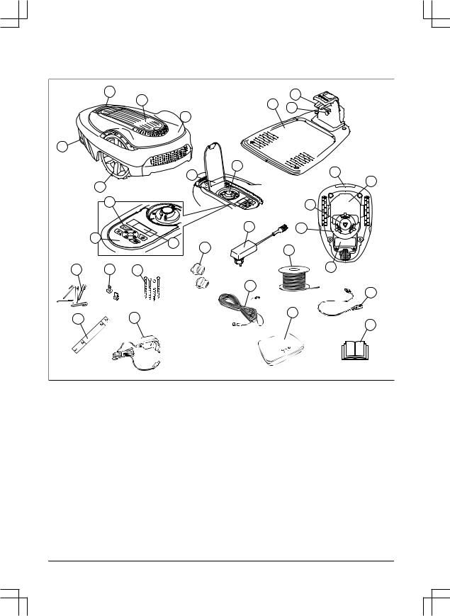
The numbers in the figure represent:
1.Body
2.Hatch to display and keypad
3.Stop button
4.Rear wheel (SILENO city) / Rear wheels (SILENO life)
5.Front wheels
6.Charging station
7.Contact strips
8.LED for operation check of the charging station, boundary wire and guide wire
9.Cutting height adjustment
10.Rating plate
11.Display
12.Keypad
13.ON/OFF button
14.Cutting system
15.Blade disc
16.Handle
17.Chassis box with electronics, battery and motors
18.Battery cover
19.Power supply (the appearance of the power supply may differ depending on market)
20.Loop wire for boundary loop and guide wire
21.Couplers for loop wire
22.Stakes
23.Connector for the loop wire
24.Screws for securing the charging station
4 - Introduction |
953 - 002 - 12.12.2018 |
25.Measurement gauge for help when installing the boundary wire (the measurement gauge is broken loose from the box)
26.smart gateway power supply (only for smart model)
27.Low voltage cable
28.smart gateway (only for smart model)
29.smart gateway LAN-cable (only for smart model)
30.Operator’s Manual and Quick Guide
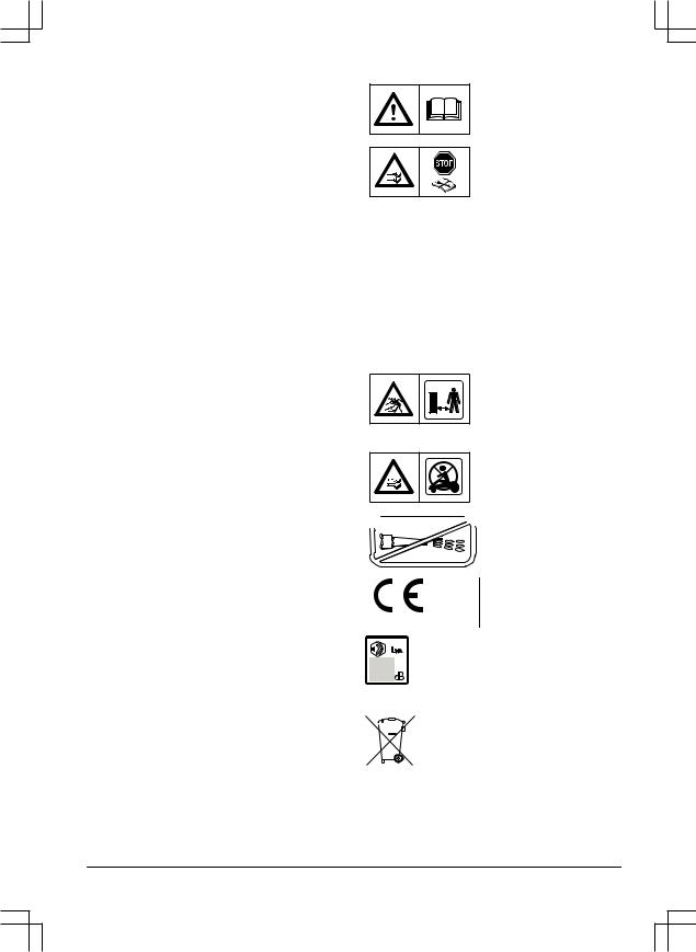
1.3 Symbols on the product
These symbols can be found on the product. Study them carefully.
WARNING: Read the user instructions before operating the product.
WARNING: Operate the disabling device before working on or lifting the
product.
The product can only start if the ON/OFF button is pressed and the indicator lamp is lit. Also, the correct PIN code must be entered. Before any inspections or maintenance is done, turn off the product and check that the indicator lamp on the ON/OFF button is not lit.
WARNING: Keep a safe distance from the product when operating. Keep
your hands and feet away from the rotating blades.
WARNING: Do not ride on the product. Never put your hands or feet close to or under the product.

 Do not use a high-pres-


 sure washer.
This product conforms to the applicable EC Directives.
Noise emission to surroundings. The product’s emissions are set out in
Technical data on page 49 and on the rating plate.
 It is not permitted to dispose this product as normal household waste. Ensure that the product is recycled in accordance with local legal
  requirements.
953 - 002 - 12.12.2018 |
Introduction - 5 |
The low voltage cable must not be |
shortened, extended or spliced. |
 Do not use a trimmer nearby the low

 voltage cable. Be careful when

 trimming edges where the cables are


 placed.
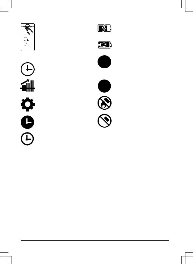
1.4 Symbols on the display
The schedule function controls when the product cuts the lawn.
The SensorControl function automatically adapts the cutting intervals to the grass growth.
The settings function is where the general settings for the products are set.
The product will not cut the grass due to the schedule function.
 The product overrides the schedule function.
The battery indicator shows the charge level of the battery. When the product charges the symbol flashes.
The product is put in the charging station but do not charge the battery.
 The product is set in ECO-mode.
1.5 Symbols on the battery
 Read the user instructions.
Do not discard the battery into fire and do not expose the battery to a heat source.
 Do not immerse the battery into water.
6 - Introduction |
953 - 002 - 12.12.2018 |
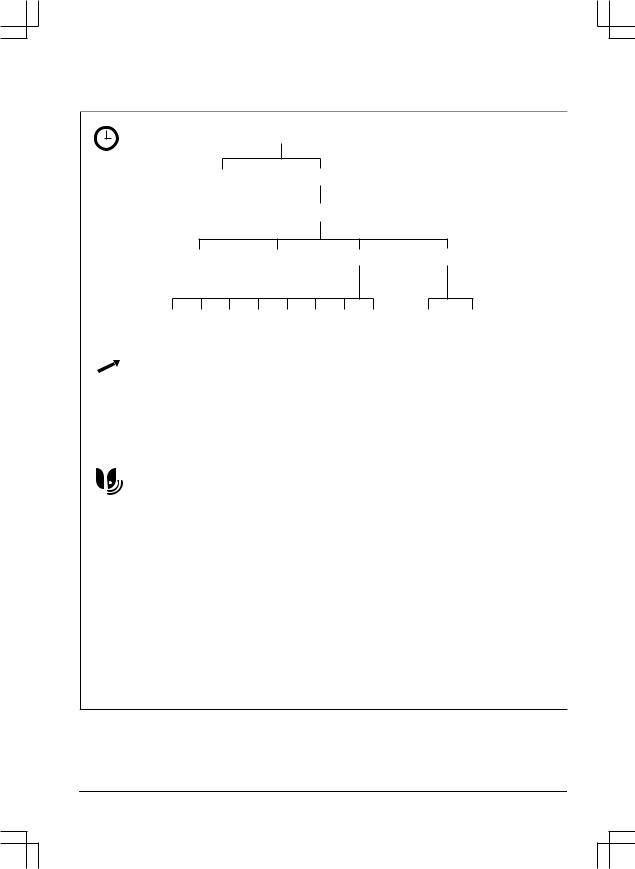
1.6 Menu structure overview
Schedule
Wizard Advanced
Overview week
Period 1 |
Period 2 |
Copy |
Reset |
|
|
|
|
|
|
|
All |
Mo |
Tu |
We |
Th |
Fr Sa |
Su |
Current All week |
|||||
|
|
|
|
|
|
|
days |
|
|
|
|
|
|
|
|
|
day |
||
|
|
|
|
|
|
|
|
SensorControl** |
|
|
|
|
|
|
|
||||
|
|
|
|
|
|
|
|
|
|
|
|
|
|
|
|
|
|
|
|
|
|
|
|
|
|
|
|
|
|
|
|
|
|
|
|
|
|
|
|
|
|
|
|
|
|
|
|
|
|
|
|
|
|
|
|
|
|
|
|
|
|
|
|
|
|
|
Use |
|
Cutting time |
|
|
|
|
|
|
|
|||
|
|
|
|
|
|
|
SensorControl |
|
|
|
|
|
|
|
|
|
|
||
|
|
|
|
|
|
|
|
|
|
|
|||||||||
|
|
|
|
|
|
|
|
|
|
|
|
|
|
|
|
|
|
|
|
|
|
|
|
|
|
|
|
|
|
Low/Mid/High |
|
|
|
|
|
|
|
||
|
|
|
|
|
|
|
|
smart system* |
|
|
|
|
|
|
|
|
|
||
|
|
|
|
|
|
|
|
|
|
|
|
|
|
|
|
|
|
|
|
|
|
|
|
|
|
|
|
|
|
|
|
|
|
|
|
|
|
|
|
|
|
|
|
|
|
|
|
|
|
|
|
|
|
|
|
|
|
|
|
|
|
|
|
|
|
|
Exclude |
|
Status |
|
|
|
|
|
|
|
|||
|
|
|
|
|
|
|
device |
|
|
|
|
|
|
|
|
|
|
|
|
|
|
|
|
|
|
|
|
|
|
|
|
||||||||
|
|
|
|
|
|
|
|
|
|
|
|
|
|
|
|
|
|
|
|
|
|
|
|
|
|
|
|
|
|
Connected |
|
|
|
|
|
|
|
||
|
|
|
|
|
|
|
|
|
|
|
|
|
|
|
|
|
|
|
|
|
|
|
|
|
|
|
|
|
|
Yes/No |
|
|
|
|
|
|
|
||
|
|
|
|
|
|
|
|
|
|
|
|
|
|
Signal |
|
|
|
|
|
|
|
|
|
|
|
|
|
|
|
|
|
|
|
strength |
|
|
|
|
|
|
|
|
|
|
|
|
|
|
|
|
|
|
|
|
|
|
|
|
|
|
|
|
|
|
|
|
|
|
|
|
|
|
|
|
|
|
|
|
|
|
|
|
|
|
|
|
|
|
|
|
|
|
|
Good |
Poor |
Bad |
|||
* smart SILENO city and smart SILENO life ** SILENO life and smart SILENO life
953 - 002 - 12.12.2018 |
Introduction - 7 |

1.7 Menu structure overview
Settings
Security |
Lawn coverage |
Installation |
General |
Area 1-3
Security level |
|
Advanced |
|||||
|
|
|
|
|
|
|
|
|
|
|
|
|
|
|
|
|
|
|
|
|
|
|
|
|
|
|
New loop |
|
Change |
||
|
|
|
signal |
|
PIN code |
||
|
|
|
|
|
|
|
|
|
|
|
|
|
|
|
|
Low Medium* High
Starting |
Drive past |
ECO |
Mower |
point |
wire |
mode |
house |
Time & |
Language |
Country |
Reset all |
About |
date |
|
|
user setting |
|
How? How |
How |
Disable |
More Set time |
Set date |
Time format |
Date format |
||
far? |
often? |
|
|
|
|
|
|
|
|
|
|
|
|
|
|
||
|
|
|
|
|
|
|
|
|
|
|
|
|
|
|
|
|
|
|
|
Test |
Reset |
|
|
|
||
* SILENO life, smart SILENO life
8 - Introduction |
953 - 002 - 12.12.2018 |
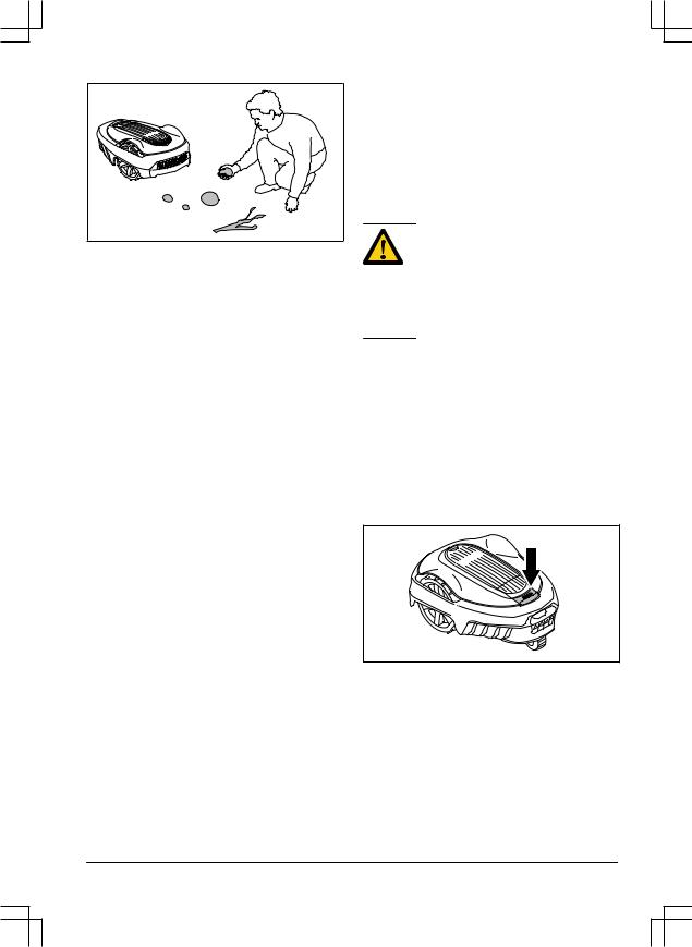
1.8 Display
The display on the product shows information and settings of the product.
To access the display, push the STOP button.
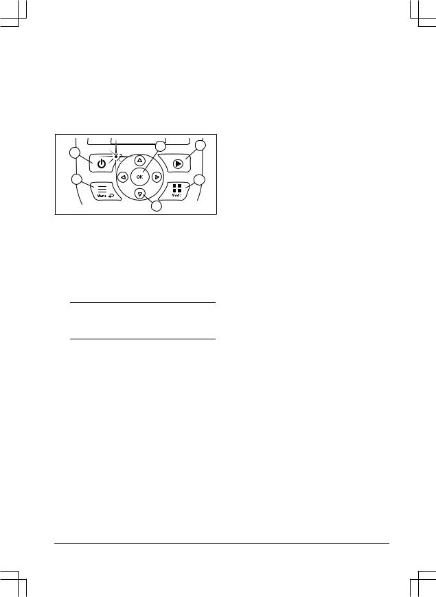
1.9 Keypad
The keypad consists of 6 groups of buttons:
5 |
2 |
1 |
|
3 |
4 |
6 |
|
1.The ON/OFF button is used to turn the product ON/OFF. The indicator lamp on the ON/OFF button is an important status indicator. Refer to The indicator lamp on page 29.
2.The Start button is used to start the operation of the product.
3.The Menu button is used to go to the main menu.
Note: The Menu button is also used as a Back button, that is, when moving back up in the menu lists.
4.The Mode button is used to choose operating mode, for example, Main area or
Park.
5.The OK button is used to confirm the chosen settings in the menus.
6.The arrow keys are used to navigate in the menu. The up/down arrow keys are also used to enter digits, for example, PIN code, time and date
953 - 002 - 12.12.2018 |
Introduction - 9 |
2 Safety
2.1 Safety definitions
Warnings, cautions and notes are used to point out specially important parts of the manual.
WARNING: Used if there is a risk of injury or death for the operator or bystanders if the instructions in the manual are not obeyed.
CAUTION: Used if there is a risk of damage to the product, other materials or the adjacent area if the instructions in the manual are not obeyed.
Note: Used to give more information that is necessary in a given situation.
2.2 General safety instructions
The following system is used in the Operator’s Manual to make it easier to use:
•Text written in italics is a text that is shown on the display of the product or is a reference to another section in the Operator’s Manual.
•Text written in bold is one of the buttons on the keypad of the product.
•Text written in UPPERCASE and italics refer to the different operating modes available in the product.
10 - Safety |
953 - 002 - 12.12.2018 |
2.2.1 IMPORTANT. READ CAREFULLY BEFORE USE. KEEP FOR FUTURE REFERENCE
The operator is responsible for accidents or hazards occurring to other people or property.
This appliance is not intended for use by persons (including children) with reduced physical, sensory or mental capabilities (that could affect a safe handling of the product), or lack of experience and knowledge, unless they have been given supervision or instruction concerning use of the appliance by a person responsible for their safety.
This appliance can be used by children aged from 8 years and above and persons with reduced physical, sensory or mental capabilities or lack of experience and knowledge if they have been given supervision or instruction concerning use of the appliance in a safe way and understand the hazards involved. Local regulations may restrict the age of the operator. Cleaning and maintenance shall not be made by children without supervision.
Never connect the power supply to an outlet if the plug or cord is damaged. Worn or damaged cord increase the risk of electric shock.
Only charge the battery in the included charging station. Incorrect use may result in electric shock, overheating or leaking of corrosive liquid from the battery. In the event of leakage of electrolyte, flush with water/neutralizing agent. Seek medical help if it comes in contact with the eyes.
Use only original batteries recommended by the manufacturer. Product safety cannot be guaranteed with other than original batteries. Do not use non-rechargeable batteries.
The appliance must be disconnected from the supply mains when removing the battery.
953 - 002 - 12.12.2018 |
Safety - 11 |
WARNING: The product can be dangerous if used incorrectly.
WARNING: Do not use the product when persons, especially children, or animals, are in the work area.
WARNING: Keep your hands and feet away from the rotating blades. Never put your hands or feet close to or under the product when the motor is running.
2.3 Safety instructions for operation
2.3.1 Use
•The product is designed to mow grass in open and level ground areas. It may only be used with the equipment recommended by the manufacturer. All other types of use are incorrect. The manufacturer’s instructions with regard to operation/maintenance must be followed precisely.
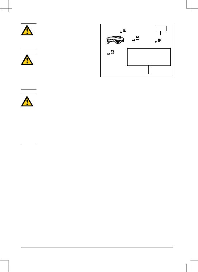
•Warning signs shall be placed around the work area of the product if it is used in public areas. The signs shall have the following text: Warning! Automatic lawnmower!
Keep away from the machine! Supervise children!
•Use the operating mode Park or turn off the product when persons, especially children, or animals, are in the work area. It is recommended to program the product for use during hours when the area is free from activity, e.g. at night. Refer to To set the schedule on page 23. Consider that certain species, e.g. hedgehogs, are active at night. They can potentially be harmed by the product.
•The product may only be operated, maintained and repaired by persons that are fully conversant with its special characteristics and safety regulations. Please read the Operator’s Manual carefully and make sure you understand the instructions before using the product.
•It is not permitted to modify the original design of the product. All modifications are made at your own risk.
•Check that there are no stones, branches, tools, toys or other objects on the lawn that can damage the blades. Objects on the lawn can also lead to the product getting stuck.
Help may be required to remove the object before the product can continue mowing. Always turn off the product using the ON/OFF button before clearing a blockage.
12 - Safety |
953 - 002 - 12.12.2018 |
•Start the product according to the instructions. When the product is turned on, make sure to keep your hands and feet away from the rotating blades. Never put your hands and feet under the product.
•Never touch moving hazardous parts, such as the blade disc, before it has come to a complete stop.
•Never lift up the product or carry it around when it is turned on.
•Do not let persons who do not know how the product works and behaves use it.
•The product must never be allowed to collide with persons or other living creatures. If a person or other living creature comes in the product’s way it shall be stopped immediately. Refer to Stop on page 30.
•Do not put anything on top of the product or its charging station.
•Do not allow the product to be used with a defective guard, blade disc or body. Neither should it be used with defective blades, screws, nuts or cables. Never connect a damaged cable, or touch a damaged cable before it is disconnected from the supply.
•Do not use the product if the ON/OFF button does not work.
•Always switch off the product using the ON/OFF button when the product is not in use. The product can only start when the ON/OFF button has been turned on and the correct PIN code has been entered.
•GARDENA does not guarantee full compatibility between the product and other types of wireless systems such as remote controls, radio transmitters, hearing loops, underground electric animal fencing or similar.
•Metal objects in the ground (for example reinforced concrete or anti-mole nets) can
result in a stoppage. The metal objects can cause interference with the loop signal which then can lead to a stoppage.
•Operation and storage temperature is 0-50 °C / 32-122 °F. Temperature range for charging is 0-45 °C / 32-113 °F. Too high temperatures might cause damage to the product.
2.3.2Battery safety
WARNING: Lithium-ion batteries can explode or cause fire if disassembled, short-circuited, exposed to water, fire, or high temperatures. Handle carefully, do not dismantle, open the battery or use any type of electrical/mechanical abuse. Avoid storage in direct sunlight.
For more information about the battery, refer to
Battery on page 35
2.3.3 How to lift and move the product
To safely move from or within the work area:
1.Press the STOP button to stop the product. If security is set to high level (refer to To set the security level on page 23) the PIN code has to be entered. The PIN code contains four digits and is selected when you start the product for the first time. Refer to To do the basic settings on page 21.
2.Press the ON/OFF button and make sure the product is turned off. Check that the indicator lamp on the ON/OFF button is not lit. This means that the product is disabled. Refer to The indicator lamp on page 29.
953 - 002 - 12.12.2018 |
Safety - 13 |
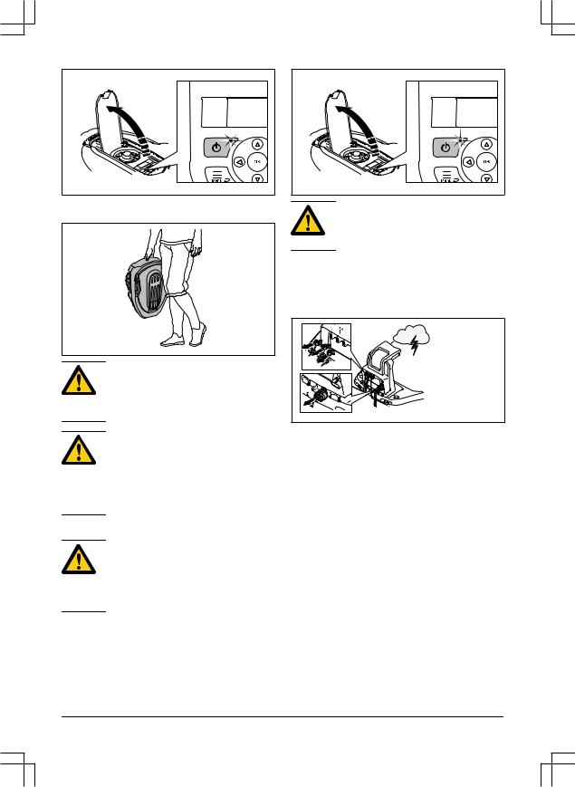
3.Carry the product by the handle with the blade disc away from the body.
WARNING: The product must be turned off before lifting it. The product is disabled when the indicator lamp on the ON/OFF button is not lit.
CAUTION: Never use a high-pressure washer to clean the product. Never use solvents for cleaning.
Inspect the product weekly and replace any damaged or worn parts. Refer to Introduction - maintenance on page 33.
2.3.5 In the event of a thunderstorm
CAUTION: Do not lift the product when it is parked in the charging station. It can damage the charging station and/or the product. Press STOP and pull the product out of the charging station before lifting it.
2.3.4 Maintenance
WARNING: The product must be turned off before any maintenance is done. The product is disabled when the indicator lamp on the ON/OFF button is not lit.
To reduce the risk of damage to electrical components in the product and the charging station, we recommend that all connections to the charging station are disconnected (power supply, boundary wire and guide wire) if there is a risk of a thunderstorm.
1.Mark the wires to simplify reconnecting. The charging station’s connections are marked R, L and GUIDE.
2.Disconnect all connected wires and the power supply.
3.Connect all the wires and the power supply if there is no longer a risk of thunder. It is important that each wire is connected to the right place.
14 - Safety |
953 - 002 - 12.12.2018 |
3 Installation
3.1 Introduction - Installation
WARNING: Read and understand the safety chapter before you install the product.
CAUTION: Only use original spare parts and installation material.
Note: Refer to www.gardena.com for more information about installation.
3.2 Before the installation of the wires
You can select to attach the wires with stakes or bury them. You can use the 2 procedures for the same work area.
•Bury the boundary wire or the guide wire if you are going to use a dethatcher on the work area. If not, attach the boundary wire or guide wire with stakes.
•Cut the grass before you install the product. Make sure that the grass is maximum 4 cm / 1.6 in.
Note: The first weeks after installation the perceived sound level when cutting the grass may be higher than expected. When the product has cut the grass for some time, the perceived sound level is much lower.
3.3 Before the installation of the product
•Make a blueprint of the work area and include all obstacles.
•Make a mark on the blueprint where to put the charging station, the boundary wire and the guide wire.
•Make a mark on the blueprint where the guide wire connects to the boundary wire. Refer to To install the guide wire on page 20.
•Fill in holes in the lawn.
Note: Holes with water in the lawn can cause damage to the product.
3.3.1 To examine where to put the charging station
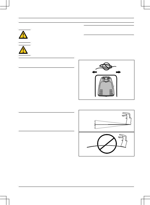
•Keep a minimum 2 m / 6.6 ft. of free space in front of the charging station.
•Keep a minimum of 30 cm / 12 in. of free space to the right and left of the center of the charging station.
•Put the charging station near an outdoor power outlet.
•Put the charging station on a level surface.
953 - 002 - 12.12.2018 |
Installation - 15 |
MAX +/- 2 CM / 0.8 IN.
•Put the charging station in the lowest possible section of the work area.
•Put the charging station in an area with protection from the sun.
•If the charging station is installed on an island, make sure to connect the guide wire to the island. Refer to To make an island on page 17.
CAUTION: Do not put the low-voltage cable in a coil or below the charging station plate. The coil causes interference with the signal from the charging station.
3.3.3 To examine where to put the boundary wire
CAUTION: If the work area is adjacent to water bodies, slopes, precipices or a public road, the boundary wire must have a protective wall. The wall must be minimum 15 cm / 6 in. in height.
3.3.2 To examine where to put the power supply
•Put the power supply in an area with a roof and protection from the sun and rain.
•Put the power supply in an area with good airflow.
•Use a residual-current device (RCD) when you connect the power supply to the power outlet.
WARNING: Do not change the power supply. Do not cut or extend the lowvoltage cable. There is a risk of electrical shock.
Low-voltage cables of different lengths are available as accessories.
CAUTION: Make sure that the blades on the product do not cut the lowvoltage cable.
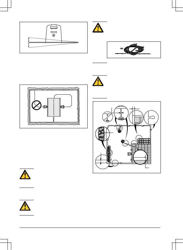
•Put the boundary wire around all of the work area (A). Adapt the distance between the boundary wire and obstacles.
•Put the boundary wire 35 cm / 14 in. (B) from an obstacle that is more than 5 cm / 2 in. high.
•Put the boundary wire 30 cm / 12 in. (C) from an obstacle that is 1-5 cm / 0.4-2 in. high.
•Put the boundary wire 10 cm / 4 in. (D) from an obstacle that is less than 1 cm / 0.4 in.
16 - Installation |
953 - 002 - 12.12.2018 |

•If you have a paving stone path that is in level with the lawn, put the boundary wire below the paving stone.
Note: If the paving stone is minimum 30 cm / 12 in. wide, use the factory setting for the Drive Past Wire function to cut all the grass adjacent to the paving stone.
CAUTION: Do not let the product operate on gravel.
•If you make an island, put the boundary wire that runs to and from the island near together (E). Put the wires in the same stake.
•Make an eyelet (F) where the guide wire is to be connected to the boundary wire.
CAUTION: Do not make sharp bends when you install the boundary wire.
CAUTION: For careful operation without noise, isolate all obstacles such as trees, roots and stones.
3.3.3.1 To put the boundary wire in a slope
•SILENO city and smart SILENO city: For slopes steeper than 25% inside the work area, isolate the slope with boundary wire.
•SILENO life and smart SILENO life: For slopes steeper than 30% inside the work area, isolate the slope with boundary wire.
•For slopes steeper than 10% along the outer edge of the lawn, put the boundary wire 20 cm / 8 in. (A) from the edge.
•For slopes adjacent to a public road, put a fence or a protective wall along the outer edge of the slope.
3.3.3.2 Passages
A passage is a section that has boundary wire on each side and that connects 2 work areas. The passage must be a minimum of 60 cm / 24 in. wide.
Note: If a passage is less than 2 m / 6.5 ft. wide, install a guide wire through the passage.
3.3.3.3 To make an island
•Put the boundary wire to and around the obstacle to make an island.
•Put the 2 sections of boundary wire that run to and from the obstacle together.
•Put the 2 sections of boundary wire in the same stake.
CAUTION: Do not put a section of boundary wire across the other. The sections of boundary wire must be parallel.
CAUTION: Do not put the guide wire across the boundary wire, for example a boundary wire that goes to an island.
953 - 002 - 12.12.2018 |
Installation - 17 |
Loading...