


Furuno MFD8, MFDBB, MFD12, DRS4A, DRS12A User Manual
...NavNet 3D FAQ v2.0
Furuno USA, Inc
Table of Contents |
|
|
1. NavNet 3D System.................................................................................................................... |
1 |
|
Q1.SYS |
How many NavNet 3D MFDs are allowed in one network?....................................... |
1 |
Q2.SYS |
Can I connect multiple position, depth and other data sensors to the system?......... |
1 |
Q3.SYS |
How many Digital Radar Sensors (DRS) can be installed in one network?............... |
1 |
Q4.SYS |
How many Fish Finders can be installed in one network? ........................................ |
1 |
Q5.SYS |
What is the NavNet 3D memory capacity?................................................................ |
1 |
Q6.SYS |
Does MFD have a capability to convert NMEA2000<-->NMEA0183?....................... |
1 |
Q7.SYS |
Can Engine Data be displayed on MFD? .................................................................. |
1 |
Q8.SYS |
What is the purpose of Audio In/Out?........................................................................ |
2 |
Q9.SYS |
What is shared in the network?................................................................................. |
2 |
Q10.SYS |
What is the difference between MFD12 and DCU12? ........................................... |
2 |
Q11.SYS |
Which combination of MFD+DRS requires the Power Supply Unit?...................... |
2 |
2. NavNet 3D Connections........................................................................................................... |
3 |
|
Q1.CON |
Can I connect a USB mouse?................................................................................... |
3 |
Q2.CON |
What is Power Synchronization?............................................................................... |
3 |
Q3.CON |
Can I connect non-Furuno devices to the HUB101 (PC, Sensor…)?........................ |
3 |
Q4.CON |
Can a standard Ethernet Switch be used for NavNet 3D? ........................................ |
4 |
Q5.CON |
How is the BB Keyboard Control Unit (MCU-001) connected to the BB Processor?.4 |
|
Q6.CON |
Is it possible to connect dual monitors and dual control heads to an MFDBB?......... |
4 |
Q7.CON |
If two monitors with different sizes and different native resolutions are connected to |
|
the MFDBB, what will happen? ................................................................................................... |
5 |
|
Q8.CON |
How are NMEA2000 sensors connected? ................................................................ |
5 |
Q9.CON |
Is it possible to terminate a NMEA2000 bus in the DRS? ......................................... |
6 |
Q10.CON |
How many NMEA2000 sensors can be connected directly to DRS?..................... |
6 |
Q11.CON |
Is the NMEA2000 port on the DRS a standard NMEA2000 Port? ......................... |
6 |
Q12.CON |
Does the DRS need to be turned “ON” for the NMEA2000 data port to be active?6 |
|
Q13.CON |
How many NMEA0183 ports are provided on every NN3D MFD? ........................ |
6 |
Q14.CON |
What type of Heading inputs are supported by NavNet 3D? ................................. |
7 |
Q15.CON |
Is it possible to connect multiple GPS / Sensors? . Error! Bookmark not defined. |
|
3. Compatibility............................................................................................................................. |
8 |
|

Q1.COMP |
|
Are NavNet 1/vx2 systems compatible with NavNet 3D? ...................................... |
8 |
|
Q5.COMP |
|
Can an AIS receiver other than FURUNO be used for NavNet 3D? ...................... |
8 |
|
Q6.COMP |
|
Can VX2 network cable be used for NavNet 3D? .................................................. |
8 |
|
Q9.COMP |
|
Can FAR2xx7 radar be connected to NavNet 3D? ................................................ |
8 |
|
Q10.COMP |
Can FCV1150 Sounder be connected to NavNet3D? ........................................ |
8 |
||
4. Chart .......................................................................................................................................... |
|
|
|
9 |
Q1.CHART |
Are current Navnet vx2 CMAP or Navionics Charts compatible with NavNet 3D? |
|||
|
|
|
9 |
|
Q2.CHART |
Which charts come preloaded in NN3D systems supplied in North America?? .9 |
|||
Q3.CHART |
What is the chart coverage in the USA? ............................................................ |
9 |
||
Q4.CHART |
What is the chart coverage outside the USA? .................................................... |
9 |
||
Q5.CHART |
How are the charts installed in NavNet 3D? ....................................................... |
9 |
||
Q6.CHART |
Can I directly load NOAA charts from the NOAA www site? ............................ |
10 |
||
Q7.CHART |
Can I update charts outside the USA? ............................................................. |
10 |
||
5. Chart Plotter............................................................................................................................ |
11 |
|||
Q1.PLOT |
|
What is the “Ghost Cursor”? ................................................................................ |
11 |
|
Q2.PLOT |
|
What is the Minimum/Maximum Zoom Range? ................................................... |
11 |
|
Q3.PLOT |
|
How many points (waypoints/marks) can be stored? ........................................... |
11 |
|
Q4.PLOT |
|
How many points for ship's tracks? ..................................................................... |
11 |
|
Q5.PLOT |
|
How many routes can be stored? ........................................................................ |
11 |
|
Q6.PLOT |
|
Is Heading used in the NN3D Plotter Modes? ..................................................... |
11 |
|
Q7.PLOT |
|
Is PBG (Personal Bathymetric Generator) available on NavNet 3D? .................. |
11 |
|
6. Radar – Digital Radar Sensors (DRS) ................................................................................... |
12 |
|||
Q1.DRS |
|
Do all NavNet 3D DRS products have High Speed antenna capability? ................. |
12 |
|
Q2.DRS |
|
What are the changes in the DRS AUTO performance? ......................................... |
12 |
|
Q3.DRS |
|
Is the ARPA function an option like older Navnet Systems?.................................... |
12 |
|
Q4.DRS |
|
Is GPS COG information allowed for Heading and ARPA capability? ..................... |
12 |
|
Q5.DRS |
|
Do NavNet 3D DRS products all have Dual Range antenna capability?................. |
12 |
|
Q6.DRS |
|
What is “Time Zero Radar”?.................................................................................... |
12 |
|
Q7.DRS |
|
How does Radar Overlay function?......................................................................... |
12 |
|
7. Fish Finder |
.............................................................................................................................. |
13 |
||
Q1.FF |
What is the new Airmar Transducer ID function available with NN3D and the DFF1 and |
|||
DFF3?? 13 |
|
|
||
Q2.FF |
What do I need to utilize the new Heaving Compensation feature, and what does it |
|||
provide?? .................................................................................................................................. |
|
|
13 |
|
8. Camera/Video.......................................................................................................................... |
14 |
|||
Q1.CAM |
|
What ...................types of IP Cameras can be connected to NavNet 3D systems? |
14 |
|
Q2.CAM |
|
How ...............................many IP Camera and analog video inputs are available? |
14 |
|
Q3.CAM |
|
Can .........................................the analog video input be distributed in a network? |
14 |
|
Q4.CAM |
|
What ...................................................................is the video output of the MFDs? |
14 |
|
|
|
|
|
|

1. NavNet 3D System
Q1.SYS |
How many NavNet 3D MFDs are allowed in one network? |
|
Any combination of up to 10 (ten) MFDs are allowed in one Network. However, the |
|
actual number of displays in the system may be higher if MFDBBs are installed |
|
using “Clone” or “Extended” Display Mode. More information about the Clone and |
|
Extended Modes for the MFDBB can be found in this document |
Q2.SYS |
Can I connect multiple position, depth and other data sensors to the |
|
system? |
|
Multiple sensors of the same or different kinds (i.e. two GPS Sensors) may be |
|
connected to any NN3D network for backup purposes. When multiple sensors |
|
providing independent but redundant data are connected, the installer will have to |
|
define the primary sensor at the Master MFD during installation. Primary sensor |
|
selections are global settings, as they will be used and displayed by all NN3D |
|
MFDs in a network. All other sensors providing the redundant information will be |
|
used as “Back-Up” sensors. NN3D will automatically “Switch” and utilize these |
|
back-up sensors in the event that a failure occurs with the primary sensor. |
Q3.SYS |
How many Digital Radar Sensors (DRS) can be installed in one network? |
||
|
Up to 2 (two) DRS can be installed and controlled in one network. |
||
Q4.SYS |
How many Fish Finders can be installed in one network? |
||
|
Up to two Network Fish Finders can be installed and controlled in one NN3D |
||
|
network. For example, both a DFF1 and DFF3 may be installed on one vessel and |
||
|
the operator may select which one to be enabled as the echo sounder source. This |
||
|
allows the vessel to change geographic regions and instantly select the optimal |
||
|
echo sounder source for a particular fishery. |
||
Q5.SYS |
What is the NavNet 3D memory capacity? |
||
|
All NN3D MFDs and Black Box systems have a ruggedized, shock resistant |
||
|
internal Hard Disk Drive (HDD) with 40 Gigabytes of memory storage capacity. |
||
Q6.SYS |
Does MFD have a capability to convert NMEA2000<-->NMEA0183? |
||
|
The NMEA0183 sentences and NMEA2000 PGNs that are used and accepted in |
||
|
the system can be converted and output with either/both NMEA0183/NMEA2000 |
||
|
format (except for the engine data that is input only). Note that only one type of |
||
|
data can be output at a time (one position, one depth, one heading…). In case of |
||
|
multiple GPS, the position which is output is the one currently used by the display. |
||
Q7.SYS |
Can Engine Data be displayed on MFD? |
||
|
Yes, certain engine data (up to three engines) in NMEA2000 format is compatible |
||
|
and may be displayed on any NN3D MFD in the Network. The currently accepted |
||
|
engine data is as follows: |
|
|
|
|
Engine Speed (Revolutions) |
(PGN 127488) |
|
|
Engine Boost Pressure |
(PGN 127488) |
|
|
Engine Oil Pressure |
(PGN 127489) |
|
|
Engine Temperature |
(PGN 127489) |
|
|
Engine Temperature Status |
(PGN 127489) |
|
|
Engine Warning Status |
(PGN 127489) |
1
Q8.SYS |
What is the purpose of Audio In/Out? |
|
An analog speaker can be connected to any MFD/MFDBB (for Alarm). Audio Input |
|
is provided for future applications. |
Q9.SYS |
What is shared in the network? |
|
The NN3D was designed as a network system. Radar, Sounder, IP Camera, Points, |
|
Routes, Tracks, Navigation Data, and System Settings are all shared via Ethernet |
|
on the NN3D network. |
|
Please note that the Charts are not shared across the network and need to be |
|
installed on the Internal Memory of every MFD. |
Q10.SYS |
What is the difference between MFD12 and DCU12? |
|
The MFD12 is a NN3D 12” multi-function display/processor unit, while the DCU12 |
|
is an optional integrated 12” display and MFD BB Keyboard – essentially it is a 12” |
|
display and keyboard without its own processor. The DCU12 is a suitable option for |
|
those wishing to use the advanced features of the MFDBB with a display-based |
|
keyboard. NavNet MFDBB Systems offer some unique features not available on |
|
the MFD8 and MFD12 such as a TimeZero Radar image, faster chart zoom |
|
performance, multiple USB 2.0 ports, selectable video resolutions, etc... |
|
DCU12 (BB Controller with built-in display) |
Power 24VDC
MFDBB
Network Port, RJ45 (2/5/10m)
DVI port, DVI-D (5/10m)
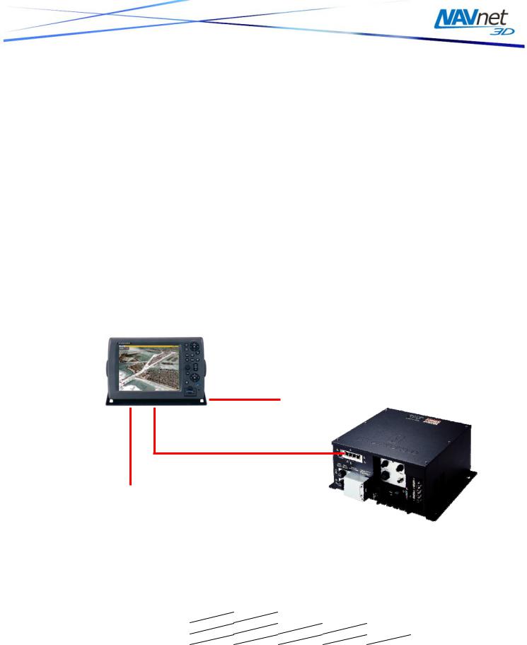
Q11.SYS |
Which combination of MFD+DRS requires the Power Supply Unit? |
||||||||
|
Power for the Digital Radar Sensor is supplied by MFD. Some combinations |
||||||||
|
require the additional Power Supply Unit in order to provide enough power for the |
||||||||
|
DRS. |
|
|
|
|
|
|
||
|
|
|
|
|
|
|
|
|
|
|
|
|
DRS2D |
DRS4D |
DRS4A |
DRS6A |
DRS12A |
DRS25A |
|
|
|
MFD8 |
|
|
PSU-012 |
PSU-012 |
PSU-012 |
PSU-013 |
|
|
|
MFD12 |
|
|
|
|
PSU-012 |
PSU-013 |
|
|
|
MFDBB |
|
|
|
|
|
PSU-013 |
|
2

2. NavNet 3D Connections
Q1.CON |
Can I connect a USB mouse? |
|
Yes. A generic USB mouse may be connected to any NN3D MFD. Virtually any "off |
|
the shelf" USB mouse (wired or RF wireless but NOT Bluetooth) will work with |
|
NN3D. However, in order to utilize full RotoKey functionality, you will need a mouse |
|
that has a scroll wheel that is also "clickable" with a middle click, which will emulate |
|
selection and confirmation of a desired RotoKey function. No loading of additional |
|
mouse software (driver) is permitted. However, the standard Mouse HID drivers will |
|
load automatically, allowing most mice and wireless mice to work fine. |
|
. |
Q2.CON |
What is Power Synchronization? |
|
A NN3D network is a system in which all components share information (navigation |
|
data, settings, points, routes, etc) with each other. To allow proper network |
|
synchronization and functionality, the MFDs have a special “sleep mode” that |
|
allows each MFD to process data while consuming low power. NN3D MFDs can be |
|
in 3 states: |
|
[ON] |
|
This is the regular mode of operation. The screen is ON and the user can interact |
|
with the device. The unit can process and share information on the network. |
|
[Sleep Mode] |
|
The screen is off and no user interaction is possible (except turning the unit ON |
|
with the Power Key). Even though the MFD seems to be turned off, it will still |
|
process and share information with other MFDs on the network. The MFD |
|
consumes lower current in this state. Any sensors attached to the MFD data ports |
|
will still function normally. |
|
[OFF] |
|
The unit is completely OFF and don’t process information. No power is consumed |
|
in this state |
|
Sleep Mode Functional Description: When the first MFD is powered ON (using the |
|
power key), all the other networked MFD(s) automatically start in sleep mode. |
|
Using the Power key on an MFD in sleep mode will turn it ON. Using the Power key |
|
on any MFD that is turned “ON” will turn the system (all the MFDs) completely OFF. |
|
If you want to turn a MFD back in sleep mode (after he has been powered ON), use |
|
the RotoKey “Sleep” |
|
IMPORTANT: Full Power Synchronization functionality requires the use of Furuno |
|
proprietary Hubs. The Internal MFDBB Hub and the optional Furuno HUB101 both |
|
provide NN3D full Power Synchronization functionality. Use of other generic |
|
Ethernet Hubs/Switches, while allowed, will not allow the MFDs to power ON |
|
automatically! Caution must also be used in that only “Two Pair” Ethernet cables |
|
may be utilized with generic hubs/switches so that the Power Synchronization |
|
signal are not short circuited by “Four Pair” Ethernet cables. |
Q3.CON |
Can I connect non-Furuno devices to the HUB101 (PC, Sensor…)? |
|
The Furuno HUB101 has a dipswitch for each Ethernet port that can |
|
enable/disable the Power Synchronization. When connected to an MFD, the switch |
|
must be setup to allow the Power Synchronization. When connected to any other |
|
device (PC, old generation sensors…) the switch MUST be setup to disable the |
|
Power Synchronization to protect other devices (such as PC) from the Power |
3

|
Synchronization signal. Here is a list of all devices that support the Power |
|
Synchronization: |
|
- All NN3D Display: MFD8, MFD12, MFDBB and DCU12 |
|
- All NN3D Radar Power Supply: PSU-012 and PSU-13 |
|
- Sounder: DFF1 and DFF3 |
Q4.CON |
Can a standard Ethernet Switch be used for NavNet 3D? |
|
Yes, a 100Mbps Switch can be used. In this case, “2-pair” Ethernet cable must be |
|
used between each MFD and the generic Ethernet Switch so that the Furuno |
|
Power Synchronization signal does not interfere with or harm the Ethernet Switch. |
Failure to do so could damage the switch and any other components connected to it. Note that when a regular switch is used, the Power Synchronization will not fully work. The use of the Furuno Hub is strongly advised. It will allow power synchronization on the network and protect your equipment such as PC when regular CAT6 (4 pair Ethernet) cable is used.
Q5.CON |
How is the BB Keyboard Control Unit (MCU-001) connected to the BB |
|
Processor? |
|
The BB Keyboard is an Ethernet Network Device that is powered directly from the |
|
MFDBB via the Ethernet Cable. This is NOT true Power-Over-Ethernet (POE). |
|
Standard POE Devices may NOT be directly connected or powered by the internal |
|
hub in the MFDBB. Direct connection of the BB Keyboard to the MFDBB allows an |
|
easy single standard Ethernet cable connection to the MFDBB Keyboard. The |
|
MFDBB Processor Unit (MPU001) contains 4 Ethernet ports. Two of these ports |
|
provide special power and are dedicated ONLY for MFDBB Keyboard connections. |
|
MFDBB Keyboards must be directly connected to one of the dedicated Ethernet |
|
ports on the MFDBB (the Keyboard cannot be connected to a Switch). Note that |
|
the supplied Ethernet cable is 5M but other lengths are available. |
Q6.CON |
Is it possible to connect dual monitors and dual control heads to an |
||||||||||
|
MFDBB? |
|
|
|
|
|
|
|
|
|
|
|
Yes, the following BB MFD installation configurations are possible. |
|
|
|
|||||||
|
|
|
|
|
|
|
|
|
|
|
|
|
|
A |
|
A |
|
A |
|
A |
|
B |
|
|
|
|
|
|
|
|
|
|
|
|
|
Single |
|
Dual (Clone Mode) |
|
Dual (Extended Mode) |
|
|
|
|
|
 Loading...