


7880
Table of contents
 Loading...
Pro 7880 / 9880 Field Repair Guide 12/20/07
Printer Component, Software Item, LCD Display, Printer Button Page 1.
Table Of Contents
Table Of Contents - - - - - - - - - - - - - - - - - - - - - - - - - - - - - - 1
Control Panel Map - - - - - - - - - - - - - - - - - - - - - - - - - - - - - 7
Component Replacement - - - - - - - - - - - - - - - - - - - - - - - - - - 19
Board (Main) Removal - - - - - - - - - - - - - - - - - - - - - - - - - - - - - - 20
Board (Main) Installation - - - - - - - - - - - - - - - - - - - - - - - - - - - - - 22
Board (Power Supply) Removal - - - - - - - - - - - - - - - - - - - - - - - - - 26
Carriage Assembly Replacement Procedure - - - - - - - - - - - - - - - - - - 28
Cartridge Release Lever Repair (Left) - - - - - - - - - - - - - - - - - - - - - - 51
Cartridge Release Lever Repair (Right) - - - - - - - - - - - - - - - - - - - - - 52
Cover (Left Side) Removal - - - - - - - - - - - - - - - - - - - - - - - - - - - - 53
Cover (Rear) Removal - - - - - - - - - - - - - - - - - - - - - - - - - - - - - - 58
Cover (Right Side) Removal - - - - - - - - - - - - - - - - - - - - - - - - - - - 61
Cover (Right Side) Installation - - - - - - - - - - - - - - - - - - - - - - - - - - 70
Cover (Top) Removal - - - - - - - - - - - - - - - - - - - - - - - - - - - - - - 84
Damper Replacement - - - - - - - - - - - - - - - - - - - - - - - - - - - - - - 86
Edge Detector (EdgeAD) Replacement - - - - - - - - - - - - - - - - - - - - - 99
Encoder Disk (Paper Feed) Removal - - - - - - - - - - - - - - - - - - - - - -103
Encoder (Paper Feed) Removal - - - - - - - - - - - - - - - - - - - - - - - - -106
Encoder Strip (Carriage) Replacement - - - - - - - - - - - - - - - - - - - - -109
Ink Bay Removal (Left) - - - - - - - - - - - - - - - - - - - - - - - - - - - - - -111
Ink Bay Replacement (Right) - - - - - - - - - - - - - - - - - - - - - - - - - -121
Paper Feed Encoder Scale Replacement - - - - - - - - - - - - - - - - - - - -131
Pressure Pump Assembly Removal - - - - - - - - - - - - - - - - - - - - - - -133
Print Head Replacement Procedure - - - - - - - - - - - - - - - - - - - - - - -141

Pro 7880 / 9880 Field Repair Guide 12/20/07
Printer Component, Software Item, LCD Display, Printer Button Page 2.
Pulley (Paper Feed) Removal - - - - - - - - - - - - - - - - - - - - - - - - - -154
Pump and Cap Assembly Installation - - - - - - - - - - - - - - - - - - - - - -156
Pump and Cap Assembly Removal - - - - - - - - - - - - - - - - - - - - - - -170
Wiper Blade Replacement - - - - - - - - - - - - - - - - - - - - - - - - - - - -178
Troubleshooting - - - - - - - - - - - - - - - - - - - - - - - - - - - - - - 185
Error Codes (Maintenance) - - - - - - - - - - - - - - - - - - - - - - - - - - -186
Error Codes (Service) - - - - - - - - - - - - - - - - - - - - - - - - - - - - - -187
00000088 - - - - - - - - - - - - - - - - - - - - - - - - - - - - - - - - - - - - -190
00000101 - - - - - - - - - - - - - - - - - - - - - - - - - - - - - - - - - - - - -191
00000103 - - - - - - - - - - - - - - - - - - - - - - - - - - - - - - - - - - - - -192
00000105 - - - - - - - - - - - - - - - - - - - - - - - - - - - - - - - - - - - - -193
00010000 - - - - - - - - - - - - - - - - - - - - - - - - - - - - - - - - - - - - -194
00010002 - - - - - - - - - - - - - - - - - - - - - - - - - - - - - - - - - - - - -195
00010004 - - - - - - - - - - - - - - - - - - - - - - - - - - - - - - - - - - - - -196
00010005 - - - - - - - - - - - - - - - - - - - - - - - - - - - - - - - - - - - - -197
0001000C - - - - - - - - - - - - - - - - - - - - - - - - - - - - - - - - - - - -198
00010014 - - - - - - - - - - - - - - - - - - - - - - - - - - - - - - - - - - - - -199
Borderless Printing Errors - - - - - - - - - - - - - - - - - - - - - - - - - - - -200
Color Shift - - - - - - - - - - - - - - - - - - - - - - - - - - - - - - - - - - - -201
Command Error - - - - - - - - - - - - - - - - - - - - - - - - - - - - - - - - -202
Communication Errors, Macintosh - - - - - - - - - - - - - - - - - - - - - - -203
Communication Errors, PC - - - - - - - - - - - - - - - - - - - - - - - - - - -205
Cover Open - - - - - - - - - - - - - - - - - - - - - - - - - - - - - - - - - - -207
Drop of Ink - - - - - - - - - - - - - - - - - - - - - - - - - - - - - - - - - - - -208
Grainy or Ghosting - - - - - - - - - - - - - - - - - - - - - - - - - - - - - - -209
Horizontal Banding - - - - - - - - - - - - - - - - - - - - - - - - - - - - - - -210

Pro 7880 / 9880 Field Repair Guide 12/20/07
Printer Component, Software Item, LCD Display, Printer Button Page 3.
Install Ink Cartridge - - - - - - - - - - - - - - - - - - - - - - - - - - - - - - -212
Invalid Ink Cartridge - - - - - - - - - - - - - - - - - - - - - - - - - - - - - - -213
Load Paper Properly - - - - - - - - - - - - - - - - - - - - - - - - - - - - - - -214
Lower Ink Lever - - - - - - - - - - - - - - - - - - - - - - - - - - - - - - - - -216
Missing Nozzle Diagnosis and Repair - - - - - - - - - - - - - - - - - - - - - -217
No Control Panel Display - - - - - - - - - - - - - - - - - - - - - - - - - - - -220
Paper Not Cut - - - - - - - - - - - - - - - - - - - - - - - - - - - - - - - - - -221
Paper Jam Error - - - - - - - - - - - - - - - - - - - - - - - - - - - - - - - - -222
Random Nozzle Firing - - - - - - - - - - - - - - - - - - - - - - - - - - - - - -223
Scratch - - - - - - - - - - - - - - - - - - - - - - - - - - - - - - - - - - - - - -224
Smudge - - - - - - - - - - - - - - - - - - - - - - - - - - - - - - - - - - - - -225
Smear - - - - - - - - - - - - - - - - - - - - - - - - - - - - - - - - - - - - - -226
Stuck In Cut Sheet Mode - - - - - - - - - - - - - - - - - - - - - - - - - - - -227
Vertical Banding - - - - - - - - - - - - - - - - - - - - - - - - - - - - - - - - -228
Adjustments - - - - - - - - - - - - - - - - - - - - - - - - - - - - - - - 229
980mm Feed Adjustment - - - - - - - - - - - - - - - - - - - - - - - - - - - -230
Auto Bi-D Adjustment - - - - - - - - - - - - - - - - - - - - - - - - - - - - - -231
Auto Bi-D [P.G. 0.8/1.6] - - - - - - - - - - - - - - - - - - - - - - - - - - - - -232
Auto Uni-D Adjustment - - - - - - - - - - - - - - - - - - - - - - - - - - - - -233
Carriage Timing Belt Tension Adjustment - - - - - - - - - - - - - - - - - - - -234
Check Alignment - - - - - - - - - - - - - - - - - - - - - - - - - - - - - - - -235
Check Cutting - - - - - - - - - - - - - - - - - - - - - - - - - - - - - - - - - -236
Check Nozzle - - - - - - - - - - - - - - - - - - - - - - - - - - - - - - - - - -237
Cleaning / Charging (Priming) - - - - - - - - - - - - - - - - - - - - - - - - - -238
Clear PF Micro Feed Adjustment [Bi-D] - - - - - - - - - - - - - - - - - - - - -239
Copy Bi-D Variables - - - - - - - - - - - - - - - - - - - - - - - - - - - - - - -240

Pro 7880 / 9880 Field Repair Guide 12/20/07
Printer Component, Software Item, LCD Display, Printer Button Page 4.
Copy Uni-D Variables - - - - - - - - - - - - - - - - - - - - - - - - - - - - - -241
CR Encoder Sensor Position Adjustment - - - - - - - - - - - - - - - - - - - -242
Cutter Blade Position Adjustment - - - - - - - - - - - - - - - - - - - - - - - -243
Head Rank ID - - - - - - - - - - - - - - - - - - - - - - - - - - - - - - - - - -245
Input Serial Number - - - - - - - - - - - - - - - - - - - - - - - - - - - - - - -246
Ink Discharge - - - - - - - - - - - - - - - - - - - - - - - - - - - - - - - - - -247
Ink Mark Sensor Level Adjustment - - - - - - - - - - - - - - - - - - - - - - -248
IM (Ink Mark) Sensor Position Adjustment - - - - - - - - - - - - - - - - - - -249
Ink Mark Sensor Adjustment for Auto Nozzle Check - - - - - - - - - - - - - -251
Nozzle Bi-D Adjustment - - - - - - - - - - - - - - - - - - - - - - - - - - - - -252
Paper Feed Belt Adjustment - - - - - - - - - - - - - - - - - - - - - - - - - - -253
Paper Feed Encoder Alignment - - - - - - - - - - - - - - - - - - - - - - - - -255
Paper Thickness Sensor Adjustment - - - - - - - - - - - - - - - - - - - - - -257
Platen Position Adjustment - - - - - - - - - - - - - - - - - - - - - - - - - - -260
Print Head Slant Adjustment (CR) - - - - - - - - - - - - - - - - - - - - - - - -262
Print Head Slant Adjustment (PF) - - - - - - - - - - - - - - - - - - - - - - - -265
RearAD Sensor Calibration - - - - - - - - - - - - - - - - - - - - - - - - - - -269
Reset PF Motor Counter - - - - - - - - - - - - - - - - - - - - - - - - - - - - -270
Reset PG Switching Counter - - - - - - - - - - - - - - - - - - - - - - - - - -271
Reset When Cleaning Unit Change - - - - - - - - - - - - - - - - - - - - - - -272
Reset When CR Unit Change - - - - - - - - - - - - - - - - - - - - - - - - - -273
Reset When Cutter Solenoid - - - - - - - - - - - - - - - - - - - - - - - - - - -274
Reset When Print Head Change - - - - - - - - - - - - - - - - - - - - - - - - -275
Reset When Pressure Motor Change - - - - - - - - - - - - - - - - - - - - - -276
RTC & USBID Adjustment - - - - - - - - - - - - - - - - - - - - - - - - - - - -277
Skew Check - - - - - - - - - - - - - - - - - - - - - - - - - - - - - - - - - - -278

Pro 7880 / 9880 Field Repair Guide 12/20/07
Printer Component, Software Item, LCD Display, Printer Button Page 5.
T&B&S + 980mm Feed Adjustment - - - - - - - - - - - - - - - - - - - - - - -279
T&B&S (Roll Paper) Adjustment - - - - - - - - - - - - - - - - - - - - - - - - -280
Washing Head - - - - - - - - - - - - - - - - - - - - - - - - - - - - - - - - - -281
Writing MAC Address - - - - - - - - - - - - - - - - - - - - - - - - - - - - - -282
Component Pictures - - - - - - - - - - - - - - - - - - - - - - - - - - - 285
Carriage Assembly - - - - - - - - - - - - - - - - - - - - - - - - - - - - - - -286
Carriage Board Picture - - - - - - - - - - - - - - - - - - - - - - - - - - - - -291
Cleaning Unit - - - - - - - - - - - - - - - - - - - - - - - - - - - - - - - - - -292
Encoder Disk (Paper Feed) Picture - - - - - - - - - - - - - - - - - - - - - - -294
Ink System Pressurization Assembly Components - - - - - - - - - - - - - - -295
Main Board Picture - - - - - - - - - - - - - - - - - - - - - - - - - - - - - - -296
Power Supply Picture - - - - - - - - - - - - - - - - - - - - - - - - - - - - - -297
Pressure Pump Assembly Picture - - - - - - - - - - - - - - - - - - - - - - - -298
Print Head Pictures - - - - - - - - - - - - - - - - - - - - - - - - - - - - - - -299
Pulley (Paper Feed) Picture - - - - - - - - - - - - - - - - - - - - - - - - - - -301
Sub Board B - - - - - - - - - - - - - - - - - - - - - - - - - - - - - - - - - - -302
Sub Board C - - - - - - - - - - - - - - - - - - - - - - - - - - - - - - - - - - -303
Reference - - - - - - - - - - - - - - - - - - - - - - - - - - - - - - - - 304
Accessories List - - - - - - - - - - - - - - - - - - - - - - - - - - - - - - - - -305
Cleaning Fluid - - - - - - - - - - - - - - - - - - - - - - - - - - - - - - - - - -306
Color Order - - - - - - - - - - - - - - - - - - - - - - - - - - - - - - - - - - -307
Connectors / Wiring - - - - - - - - - - - - - - - - - - - - - - - - - - - - - - -309
Consumable/Service Parts List - - - - - - - - - - - - - - - - - - - - - - - - -313
Firmware History (7880) - - - - - - - - - - - - - - - - - - - - - - - - - - - - -315
Firmware History (9880) - - - - - - - - - - - - - - - - - - - - - - - - - - - - -316
Firmware Update Procedure Using FWUpdate.exe - - - - - - - - - - - - - - -317

Pro 7880 / 9880 Field Repair Guide 12/20/07
Printer Component, Software Item, LCD Display, Printer Button Page 6.
Glossary - - - - - - - - - - - - - - - - - - - - - - - - - - - - - - - - - - - - -318
Ink Draining Procedure - - - - - - - - - - - - - - - - - - - - - - - - - - - - -324
Ink System Flushing Procedure - - - - - - - - - - - - - - - - - - - - - - - - -325
Ink Tube Order - - - - - - - - - - - - - - - - - - - - - - - - - - - - - - - - - -327
Prime, On or Off - - - - - - - - - - - - - - - - - - - - - - - - - - - - - - - - -328
Revision History - - - - - - - - - - - - - - - - - - - - - - - - - - - - - - - - -329
Sensors, Motors, Solenoids, and Fans - - - - - - - - - - - - - - - - - - - - -330
Service Procedure - - - - - - - - - - - - - - - - - - - - - - - - - - - - - - - -332
Service Tools - - - - - - - - - - - - - - - - - - - - - - - - - - - - - - - - - -334
Stress Test (Test Image) - - - - - - - - - - - - - - - - - - - - - - - - - - - - -335
Utilities - - - - - - - - - - - - - - - - - - - - - - - - - - - - - - - - - - 336
Adjustment Wizard2 - - - - - - - - - - - - - - - - - - - - - - - - - - - - - - -337
FWUpdate.exe - - - - - - - - - - - - - - - - - - - - - - - - - - - - - - - - - -340
NVRAM.EXE - - - - - - - - - - - - - - - - - - - - - - - - - - - - - - - - - - -344

Pro 7880 / 9880 Field Repair Guide 12/20/07
Printer Component, Software Item, LCD Display, Printer Button Page 7.
Control Panel Map
Hold for
3 seconds to reset/clear
Hold for 3 seconds
to cut roll media
Hold for 3
seconds to
clean
Power
Button
Sheet
Roll Auto Cut
Roll Auto Cut Off
Ink Levels
Maintenance
Tank Level
Media
Feed
Status
Paper Out
Ink Out
Paused
light
Paper Source
Button
User
Menu
Button
Enter / Select
Button
Press to pause the
Printer.
Roll Counter
Custom
Paper
Number
SERVICEMAN MODE: Down, Right, Pause, at power on.
SELF TESTING: Down, Right, Enter, at power on.
F/W DOWNLOAD MODE: Up, Down, Left, Right, at power on.
Maintenance Mode 1: Pause, at power on.

Pro 7880 / 9880 Field Repair Guide 12/20/07
Printer Component, Software Item, LCD Display, Printer Button Page 8.
1. PRINTER SETUP.
ROLL PAPER COUNTER: 15ft - 300ft
PLATEN GAP: *STANDARD, NARROW, WIDE, WIDER,
WIDEST
PAGE LINE: *ON, OFF
INTERFACE: *AUTO, USB, NETWORK
CODE PAGE: *PC437, PC850,
ROLL PAPER MARGIN: *DEFAULT, TOP/BOTTOM 15mm,
TOP 35/BOTTOM 15mm,15mm, 3mm
PAPER SIZE CHK: *ON, OFF
PAPER SKEW CHECK: *ON, OFF
TIME OUT: *OFF, 30SEC, 60SEC, 180SEC, 300SEC
CUTTER ADJUSTMENT: EXEC
REFRESH MARGIN: *ON, OFF
AUTO NOZZLE CHECK: *OFF, ON
AUTO CLEANING: *ON, OFF
QUIET CUT: *OFF, ON
INITIALIZE SETTINGS: EXEC
2. TEST PRINT.
NOZZLE CHECK: PRINT
NETWORK STATUS SHEET: PRINT
STATUS SHEET: PRINT
JOB INFORMATION: PRINT
CUSTOM PAPER: PRINT
4. CUSTOM PAPER.
PAPER NUMBER: *STANDARD, NO. (1-10)
PLATEN GAP: NARROW, STANDARD, WIDE, WIDER
THICKNESS PATTERN: PRINT
CUT METHOD: *STANDARD, THIN PAPER, THICK
PAPER FAST, THICK PAPER SLOW
PAPER FEED ADUST: (n.nn)%
DRYING TIME: (n.n)sec
PAPER SUCTION: *STANDARD, -1, -2, -3, -4
M/W ADJ: *STANDARD,1, 2
3. PRINTER STATUS.
VERSION: (CURRENT FIRMWARE)
PRINTABLE PAGES: (FOR EACH COLOR)
(nnnnnn)PAGES
INK LEVEL: (FOR EACH COLOR) E*****F
MAINTENANCE TANK: L E*****F, R E*****F
USAGE COUNT: INK (nnnn.n)ML, PAPER (nnnn.n)FT
CLEAR USAGE COUNT: INK:EXEC PAPER:EXEC
JOB HISTORY: N0.(n) INK:(n)ml, PAPER:(nnn)sqft
TOTAL PRINTS: (n) PA GES
SERVICE LIFE: CUTTER, CR MOTOR, PF MOTOR,
HEAD UNIT,CLEANING UNIT, PRESSURE
MOTOR (E*****F)
User Menu: Press the Menu button when
the printer displays Ready

Pro 7880 / 9880 Field Repair Guide 12/20/07
Printer Component, Software Item, LCD Display, Printer Button Page 9.
Parameter Backup and Restore Mode
Release the Paper Lever, lift 2 Ink Levers, remove the Maintenance Tank, hold the Down, Right, and Pause but-
tons and turn on the Printer.
Note: If the backup procedure fails, try re-booting the Printer and letting it come Ready. Then try the
backup / restore procedure.
F/W Download Mode
Hold the Up, Down, Left, and Right buttons and turn on the power.
Maintenance Mode 1: Press and hold the Pause button and turn on the Printer.
HEX DUMP: PRINT EXEC (In this mode, the printer prints hexadecimal values received)
LANGUAGE: *ENGLISH, FRENCH, ITALIAN, GERMAN, SPANISH, PORTUGUE, DUTCH (Panel Language)
7. NETWORK SETUP: (*DISABLE, ENABLE)
IP ADDRESS SETTING: AUTO, PANEL,
BONJOUR: *ON, OFF
INIT NETWORK SETTING: EXECUTE
5. MAINTENANCE
CUTTER REPLACEMENT: EXEC
BK Ink Change: EXEC (For Changing between Matte and
Photo Black)
POWER CLEANING: “YOU MUST MOVE INK LEVERS
WHEN CLEANING”, EXECUTE, CANCEL (102ml)
CLOCK SETTING: (mm/dd/yy hh:mm)
CONTRAST ADJUSTMENT: (nn)
6. Head Alignment.
PAPER THICKNESS: *STANDARD, (n.n)mm
ALIGNMENT: AUTO (UNI-D, BI-D 2-COLOR,
BI-D All, BI-D #1, BI-D #2,
BI-D #3)
MANUAL (UNI-D, BI-D 2-
COLOR, BI-D All,)

Pro 7880 / 9880 Field Repair Guide 12/20/07
Printer Component, Software Item, LCD Display, Printer Button Page 10.
REMAINING PPR SETUP: *ROLL, OFF (Roll enables the ROLL PAPER COUNTER)
UNIT: *FEET/INCH, METER (Set’s the unit of measure that the printer displays)
CUT PRESSURE: *100% (0%-150%) (Adjusts the Paper Cutter pressure)
SS CLEANING: EXEC (Super Strong Cleaning)(255 time limit without replacing print head and resetting life
counter)
PWR ON ROLL PPR FEED: *ON, OFF (On = Feeds the paper 3” lower, when auto cut is off)
(Off = Does not feed the paper 3” lower, when auto cut is off)
DEF AULT PANEL: EXEC (Resets to Factory Default the following User Menus: Printer Setup, Printer St atus,
Custom Paper, Head Alignment)
INK INFO MENU: (FOR EACH COLOR) MANUF ACTURER, COLOR, INK TYPE, INK CAPACITY, INK LEVEL,
PRODUCTION DATE, EXPIRATION DATE, INK LIFE, INK AGE (CSIC
information, for each
ink cartridge
)
Custom:*0 (0 - 9)
SERVICEMAN MODE: Press and hold the Down, Right, and Pause buttons, and turn on the Printer
Note: SERVICEMAN MODE turns on the USB Port even if there is an error condition.
Note: SERVICEMAN MODE must be displayed on the LCD to turn on the USB Port.
SELF TESTING:
Test:
Version: F/W: T(N or W)(nnnnnnnn.nn.nnnn) (Displays the current firmware version)
Panel: Key, LCD, LED (Button, LCD, and LED tests for the control panel)
Sensor: CR Origin: On, Off (Carriage Home Position Sensor test)
Paper: 00, 01,10,11 (Paper Thickness Sensor test)
Lever: Down, Up (Paper Release Sensor test)
HeadSlide: On, Off (Platen Gap Home Position Sensor test)
Pump: On, Off (Pump Home Position Sensor test)
InkLvr: Down/Down, Up/Down, Down/Up, UP/Up (Right and Left Ink Lever Sensor test)
Cover: Close, Open (Cover Sensor test)
MainteTank: On, ON (CSIC Contact Test)

Pro 7880 / 9880 Field Repair Guide 12/20/07
Printer Component, Software Item, LCD Display, Printer Button Page 11.
INK NOT: 1,2,3,4,5,6,7,8 (Ink Cartridge Sensor test for 8 Ink Bays)
EdgeAD: (nnn nnn) (Paper Edge Sensor test)
Edge2AD: (nnn nnn) (Ink Mark Sensor Test)
RearAD: (nnn nnn) (Rear Paper Sensor test)
Head Temp: (nn)C (Displays the current Print Head temperature in degrees centigrade)
Drv. Temp: (nn)C (Displays the current Print Head Driver temperature in degrees centigrade)
Ink Press: Off, On (Pressure Sensor test)
Take Up: (9880 Only) (Tests the absence, or presence of the Optional Take Up Reel)
Encoder: CR (nnnn) (Carriage Encoder test. Counts up, moving away from home position)
PF (nnnn) (Paper Feed Encoder test. Counts up, as the paper advances.)
Fan: Paper(ALL): (Fan test for all paper suction fans)
Paper(Duty): (200% - 0%) (Tests the fan suction for all paper suction fans)
Paper1: (Fan test for paper suction fan #1 (Right Side Fan))
Paper2: (Fan test for paper suction fan #2 (Left Side Fan (Center Fan on 9800)))
Paper3: (9880 only)(Fan test for paper suction fan #3 (Left Side Fan))
Head Drv: (Fan test for the Head Driver Cooling Fan)
Elec.: Maintenance: WasteInk: (Right Side Maintenance Tank Counter)
WasteInk2: (9880 Only)(Left Side Maintenance Tank Counter)
Wiper: (Wiping Counter)
Rubbing: (Rubbing Counter)
Lever: (Paper Release Lever Counter)
Cover: (Cover Sensor Counter)
Ink Lever: (Left and Right Ink Lever Counter)
Cr Motor: (Carriage Motor Usage Counter)
PF Motor: (Paper Feed Motor Usage Counter)
PrintNumber: (Number of printed pages)
Cleaning: (Cleaning Operations Counter)
Fire A: (Light Light Black Nozzle Array Counter)
Fire B: (Light Magenta Nozzle Array Counter)
Fire C: (Light Cyan Nozzle Array Counter)

Pro 7880 / 9880 Field Repair Guide 12/20/07
Printer Component, Software Item, LCD Display, Printer Button Page 12.
Fire D: (Light Black Nozzle Array Counter)
Fire E: (Photo/Matte Black Nozzle Array Counter)
Fire F: (Cyan Black Nozzle Array Counter)
Fire G: (Magenta Nozzle Array Counter)
Fire H: (Yellow Nozzle Array Counter)
Cut: (Paper Cutting Operations Counter)
Cute Sole: (Cutter Solenoid Counter)
Error: Error (0 - 6) (Displays the last 7 errors)
Cut Adj: Cutter: 55%
Actuator2: Cutter Sol: [Enter], Start (Tests the Cutter Solenoid)
Pump Motor: [Enter], Start (Tests the Cutter Solenoid)
Regulator Sol: [Enter], Start (Tests the Ink System Pressure Release Solenoid)
Ink Press Motor: [Enter], Start (Ink System Pressure Motor)
Edge Sns Lvl: [Enter], Start (Sets the black level of the Edge Detector)
Auto Gap Adj: Auto Uni-D: [Enter] Print (Performs and Auto Uni-D Adjustment)
Auto Bi_d PG1.6: [Enter] Print (Performs and Auto Bi-D for Platen Gap 1.6 (WIDE))
Auto Bi_d PG0.8: [Enter] Print (Performs and Auto Bi-D for Platen Gap 0.8 (NARROW))
Adjustment:
Fan: Paper(ALL)(Runs all Suction Fans), Fan Adjust *0% (-10% to +10%) (Adjusts Suction Fans)
Paper: 00, 01, 10, 11(Displays the output from the Paper Thickness Sensors)
RearAD: [Enter], Start: Exc.: RearAD: (nnn nnn nnn) (For adjusting the Rear Paper Sensor)
Check Nozzle: [Enter] Print: (Service nozzle check, displays Firmware Version, displays Head Rank)
Cutter: [Enter], Start:(Cut position check)
IM Sensor: (Adjusts sensitivity of the Edge Detector Sensor and the Ink Mark Sensor)
PlatenPos: (n.n)mm(Calibrates the Borderless Pad Positions)
PlatenPos.Chk.: (Checks the Borderless Pad Position calibration)
Rear Sens.Pos: (Calibrates the EOF position for cut sheet media)
CR Head Slant: (Performs the CR Head Slant adjustment)
PF Head Slant: PF Head BiD Adj (Pk or MK Bi-D adjustment), PF Head Slant (PF Head Slant adjust-
ment)

Pro 7880 / 9880 Field Repair Guide 12/20/07
Printer Component, Software Item, LCD Display, Printer Button Page 13.
Gap Adj: All, Uni-D, Bi-D PG1.6,Bi-D PG0.8, (Manual Bi-D and Uni-D)
Gap Adj: VSD1C: Print (Manual Bi-D and Uni-D PG 1.2)
Check Skew: (n.n)mm (Default 1.0) (Used for testing and setting the amount of allowable skew)
Feed Adj.+T&B: (Performs the 980mm, Top and Bottom Margin adjustments)
IM Thresh: IM PosAdj, IM Loss Pattern, IM Full Pattern (Calibrates the IM Sensor for Auto Nozzle Check)
Adj. Variable: [Enter] Print (Prints the numeric adjustment variables currently set)
Pump Cnt: NG(?)
VIEW COUNTERS:
CUTTER: (Count for the Cutter Blade)
CUTTER TOTAL: (Count for the Cutter Assembly)
TOTAL PAGES: (Page count for the Printer)
CR MOTOR: (Count for the Carriage Motor)
CR TOTAL: (Count for the Carriage Mechanism)
PF MOTOR: (Count for the Paper Feed Motor)
PRESSURE MOTOR: (Count for the Pressure Motor)
NOZZLE A: (Light Light Black Nozzle Array Counter)
NOZZLE B: (Light Magenta Nozzle Array Counter)
NOZZLE C: (Light Cyan Nozzle Array Counter)
NOZZLE D: (Light Black Nozzle Array Counter)
NOZZLE E: (Photo/Matte Black Nozzle Array Counter)
NOZZLE F: (Cyan Black Nozzle Array Counter)
NOZZLE G: (Magenta Nozzle Array Counter)
NOZZLE H: (Yellow Nozzle Array Counter)
FL BOX: (Count for the Flushing Box)
CLEANER: (Count for the Pump and Cap Assembly)
SPONGE: (?)
PG: (Count for the Platen Gap Assembly)
MAINT INFO:
MENU E: E1 - E17 (?)
MENU R: R1 - R9 (?)

Pro 7880 / 9880 Field Repair Guide 12/20/07
Printer Component, Software Item, LCD Display, Printer Button Page 14.
MENU S: S1 - S26 (?)
MENU A: A1 - A32 (?)
MENU B: B1 - B48 (?)
MENU P: P1 - P46 (?)
MENU M: M1 - M26 (?)
MENU O: 01 - 026 (?)
MENU F: F1- F20 (?)
MENU N: N1 - N22 (?)
SELF TESTING: Press and hold the Down, Right, and Enter buttons and turn on the Printer.
Test:
Version: F/W: T(N or W)(nnnnnnnn.nn.nnnn) (Displays the current firmware version)
Panel: Key, LCD, LED (Button, LCD, and LED tests for the control panel)
Sensor: CR Origin: On, Off (Carriage Home Position Sensor test)
Paper: 00, 01,10,11 (Paper Thickness Sensor test)
Lever: Down, Up (Paper Release Sensor test)
HeadSlide: On, Off (Platen Gap Home Position Sensor test)
Pump: On, Off (Pump Home Position Sensor test)
InkLvr: Down/Down, Up/Down, Down/Up, UP/Up (Right and Left Ink Lever Sensor test)
Cover: Close, Open (Cover Sensor test)
MainteTank: On, Off (CSIC Contact Test)
INK NOT: 1,2,3,4,5,6,7,8 (Ink Cartridge Sensor test for 8 Ink Bays)
EdgeAD: (nnn nnn) (Paper Edge Sensor test)
Edge2AD: (nnn nnn) (Ink Mark Sensor Test)
RearAD: (nnn nnn) (Rear Paper Sensor test)
Head Temp: (nn)C (Displays the current Print Head temperature in degrees centigrade)
Drv. Temp: (nn)C (Displays the current Print Head Driver temperature in degrees centigrade)
Ink Press: Off, On (Pressure Sensor test)
Take Up: (9800 Only) (Tests the absence, or presence of the Optional Take Up Reel)
Encoder: CR (nnnn) (Carriage Encoder test. Counts up, left to right)

Pro 7880 / 9880 Field Repair Guide 12/20/07
Printer Component, Software Item, LCD Display, Printer Button Page 15.
PF (nnnn) (Paper Feed Encoder test. Counts up, as the paper advances.)
Fan: Paper(ALL): (Fan test for all paper suction fans)
Paper(Duty): (200% - 0%) (Tests the fan suction for all paper suction fans)
Paper1: (Fan test for paper suction fan #1 (Right Side Fan))
Paper2: (Fan test for paper suction fan #2 (Left Side Fan (Center Fan on 9800)))
Paper3: (9800 only)(Fan test for paper suction fan #3 (Left Side Fan))
Head Drv: (Fan test for the Head Driver Cooling Fan)
Elec.: Maintenance: WasteInk: (Right Side Maintenance Tank Counter)
WasteInk2: (9880 Only)(Left Side Maintenance Tank Counter)
Wiper: (Wiping Counter)
Rubbing: (Rubbing Counter)
Lever: (Paper Release Lever Counter)
Cover: (Cover Sensor Counter)
Ink Lever: (Left and Right Ink Lever Counter)
Cr Motor: (Carriage Motor Usage Counter)
PF Motor: (Paper Feed Motor Usage Counter)
PrintNumber: (Number of printed pages)
Cleaning: (Cleaning Operations Counter)
Fire A: (Light Light Black Nozzle Array Counter)
Fire B: (Light Magenta Nozzle Array Counter)
Fire C: (Light Cyan Nozzle Array Counter)
Fire D: (Light Black Nozzle Array Counter)
Fire E: (Photo/Matte Black Nozzle Array Counter)
Fire F: (Cyan Black Nozzle Array Counter)
Fire G: (Magenta Nozzle Array Counter)
Fire H: (Yellow Nozzle Array Counter)
Cut: (Paper Cutting Operations Counter)
Cute Sole: (Cutter Solenoid Counter)
Error: Error(0 - 6) (Displays the last 7 errors)
CSIC: Slot (1 - 8), Maintenance Tank (?)

Pro 7880 / 9880 Field Repair Guide 12/20/07
Printer Component, Software Item, LCD Display, Printer Button Page 16.
Cut Adj: Cutter: 55%
Actuator2: Cutter Sol: [Enter], Start (Tests the Cutter Solenoid)
Pump Motor: [Enter], Start (Tests the Cutter Solenoid)
Regulator Sol: [Enter], Start (Tests the Ink System Pressure Release Solenoid)
Ink Press Motor: [Enter], Start (Ink System Pressure Motor)
Edge Sns Lvl: [Enter], Start (Sets the black level of the Edge Detector)
Auto Gap Adj: Auto Uni-D: [Enter] Print (Performs the Auto Uni-D Adjustment)
Auto Bi_d PG1.6: [Enter] Print (Performs the Auto Bi-D for Platen Gap 1.6 (WIDE))
Auto Bi_d PG0.8: [Enter] Print (Performs the Auto Bi-D for Platen Gap 0.8 (NARROW))
Adjustment:
Input HeadRank: (Does not function)
Fan: Paper(ALL)(Runs all Suction Fans), Fan Adjust *0% (-10% to +10%) (Adjusts Suction Fans)
Paper: 00, 01, 10, 11(Displays the output from the Paper Thickness Sensors)
Rear AD: [Enter], Start: Exc.: RearAD: (nnn nnn nnn) (For adjusting the Rear Paper Sensor)
Init.Fill: (Starts an initial fill)
Check Nozzle: [Enter] Print: (Service nozzle check, displays Firmware Version, displays Head Rank)
Cutter: (Cut position check)
IM Sensor: (Adjusts sensitivity of the Edge Detector Sensor)
PlatenPos: (n.n)mm(Calibrates the Borderless Pad Positions)
PlatenPos.Chk.: (Checks the Borderless Pad Position calibration)
Rear Sens.Pos: (Calibrates the EOF position for cut sheet media)
CR Head Slant: (Performs the CR Head Slant adjustment)
PF Head Slant: PF Head Slant (PF Head Slant adjustment), PF Head BiD Adj (Pk or MK Bi-D adjust-
ment)
Gap Adj: All, Uni-D, Bi-D PG1.6,Bi-D PG0.8, (Manual Bi-D and Uni-D)
Gap Adj: VSD1C: Print (Manual Bi-D and Uni-D PG 1.2)
Check Skew: (n.n)mm (Default 1.0) (Used for testing and setting the amount of allowable skew)
Feed Adj.+T&B: (Performs the 980mm, Top and Bottom Margin adjustments)
IM Thresh: IM PosAdj, IM Full Pattern, IM Loss Pattern (Calibrates the IM Sensor for Auto Nozzle Check)
Adj. Variable: [Enter] Print (Prints the numeric adjustment variables currently set)

Pro 7880 / 9880 Field Repair Guide 12/20/07
Printer Component, Software Item, LCD Display, Printer Button Page 17.
Clean Head: (Evacuates the ink system)
Pump Cnt: NG(?)
Counter Clear: (Clears a variety of counters)(Do not use)
Cleaning:
Std. CL1 (5.3ml)
Std. CL2 (6.3ml)
Std. CL3 (10.4ml)
Std. CL6 (?)
Init.Fill
Parameter:
Initialize:
All: Initialize OK? (Resets all of the following counters at once)
PF Resolution: Initialize OK? (Resets this counter only)
Head Record: Initialize OK? (Resets this counter only)
Wiping Record: Initialize OK? (Resets this counter only)
Rab. Record: Initialize OK? (Resets this counter only)
Waste Record: Initialize OK? (Resets this counter only)
CRmot Record: Initialize OK? (Resets this counter only)
PFmot Record: Initialize OK? (Resets this counter only)
Lever Record: Initialize OK? (Resets this counter only)
Cover Record: Initialize OK? (Resets this counter only)
Ink Lever Record: Initialize OK? (Resets this counter only)
Cutter Record: Initialize OK? (Resets this counter only)
Cleaner Record: Initialize OK? (Resets this counter only)
Update: JM: Init. Fill: (Set, Reset) (Reset, turns of f the initial fill)
InkParameter: Init. Fill: (Set, Reset) (Reset, turns off the initial fill)
HeadWash(?)
Mask Type: Dispersion, Regular (?)
PF BiD Adjust: (+/- n) (?)
Uni-D Trap: (On, Off) (?)

Pro 7880 / 9880 Field Repair Guide 12/20/07
Printer Component, Software Item, LCD Display, Printer Button Page 18.
Display: Address: (nnnn)(Used for displaying data at specific RAM addresses)
Life: CR Motor (Carriage Motor Life Counter)
PF Motor (Paper Feed Motor Life Counter)
CR+PF Motor(Carriage and Paper Feed Motor Life Counter)
Cutter (Cutter Assembly Life Counter)
Head U/D (?)
Head Lock (Head Lock Assembly Life Counter)
Cleaning (Cleaning Unit Life Counter)
Print (Print Head Life Counter)
Total Life (?)
TotalLife2 (?)
CSIC (?)
Check (?)

Pro 7880 / 9880 Field Repair Guide 12/20/07
Printer Component, Software Item, LCD Display, Printer Button Page 19.
Component
Replacement
Pro 7880 / 9880 Field Repair Guide 12/20/07
Board (Main) Removal Printer Component, Software Item, LCD Display, Printer Button Page 20.
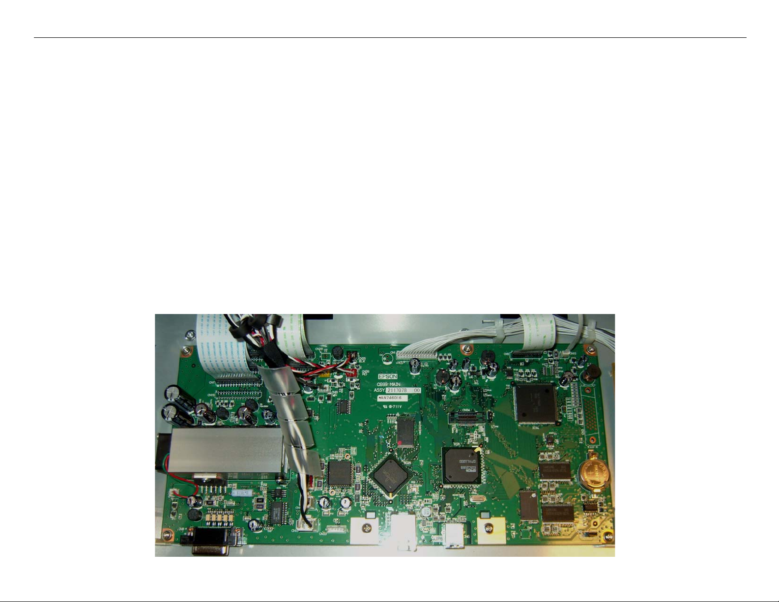
Board (Main) Removal
Note: 7880 Main Board Part # 2117093 (the part # is stamped on the board)
9880 Main Board Part # 2117078 (the part # is stamped on the board)
1. Back up the Printer’s parameters using the Parameter Backup / Restore Utility (Nvram.exe)
Note: If the Printer’s parameters can not be “backed up”, print out the Print Head Calibration value
(Head Rank). The Print Head Calibration value is printed on the Service Level Nozzle Check
(ServiceMan Mode: Self Testing: Adjustment: Check Nozzle).
2. Turn off the Printer and UNPLUG from AC.
3. Remove the Cover (Rear).
4. Unplug the Cables that attach the Main Board to the Printer..

Pro 7880 / 9880 Field Repair Guide 12/20/07
Board (Main) Removal Printer Component, Software Item, LCD Display, Printer Button Page 21.
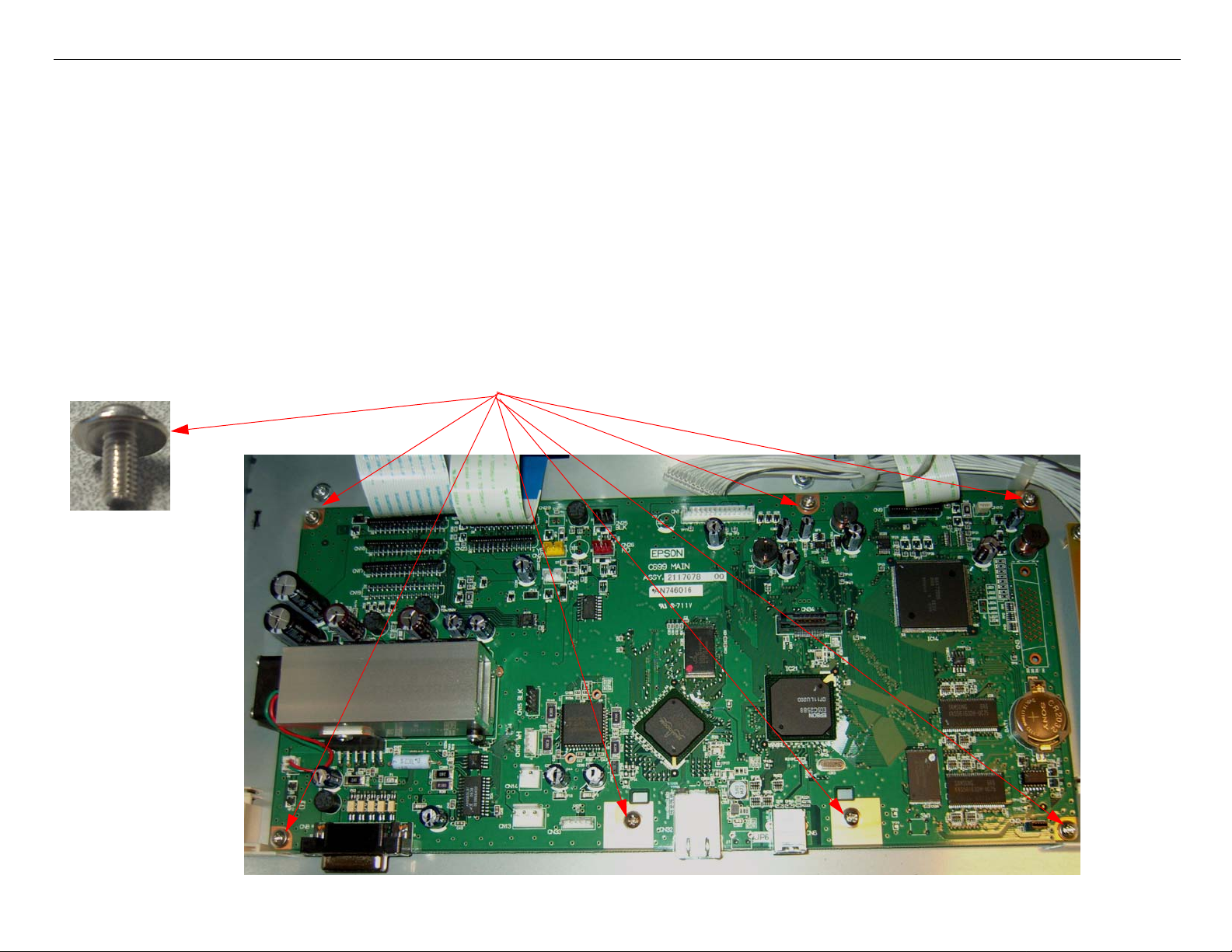
5. Remove 7 Screws, and lift out the Main Board.
1. Remove 7 Screws
2. Lift out the Main Board.
Pro 7880 / 9880 Field Repair Guide 12/20/07
Board (Main) Installation Printer Component, Software Item, LCD Display, Printer Button Page 22.
Board (Main) Installation
Note: 7880 Main Board Part # 2117093 (the part # is stamped on the board)
9880 Main Board Part # 2117078 (the part # is stamped on the board)
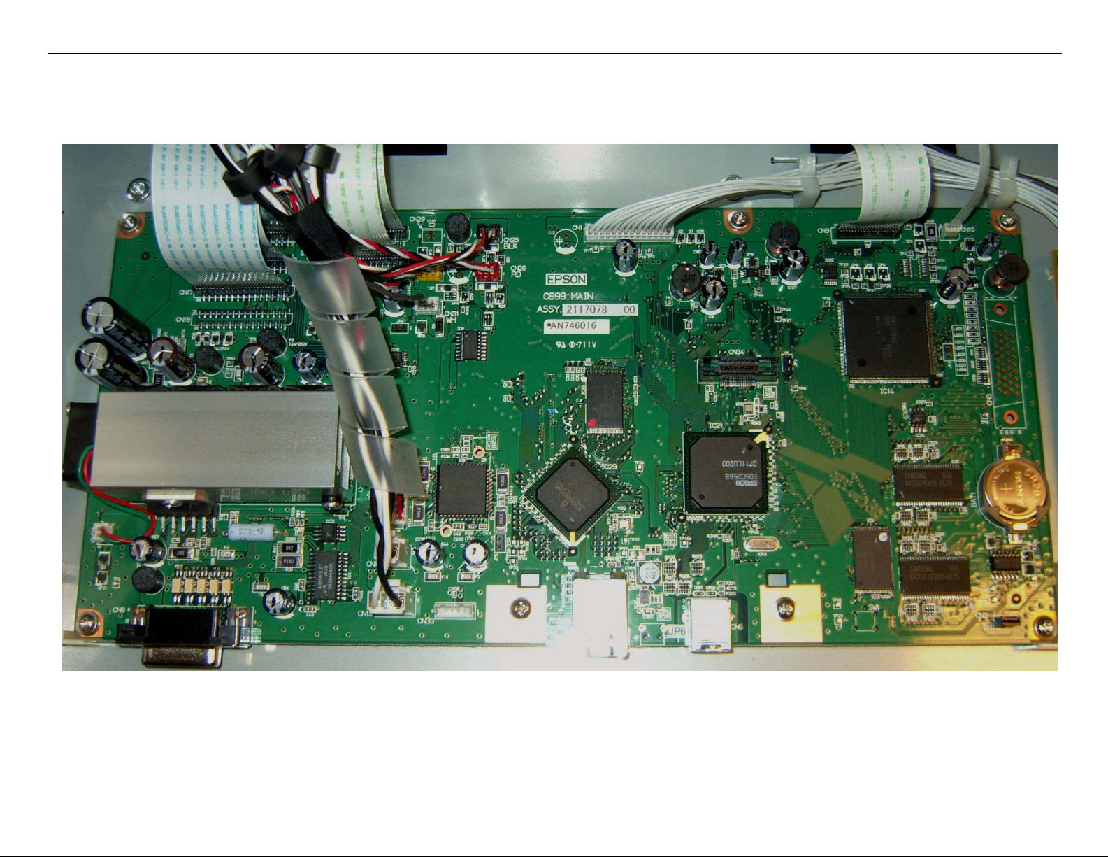
1. Compare the New Main Board to the Old Main Board. Verify that the Components, Brackets,
and Part Numbers match.
2. Fasten the new Board to the Housing with 7 Screws (see above).
2. Install 7 Screws.
1. Drop In the New Main Board.
Pro 7880 / 9880 Field Repair Guide 12/20/07
Board (Main) Installation Printer Component, Software Item, LCD Display, Printer Button Page 23.
3. Connect the Cables to the Board. Ensure that the Cables are fully seated (straight).

Pro 7880 / 9880 Field Repair Guide 12/20/07
Board (Main) Installation Printer Component, Software Item, LCD Display, Printer Button Page 24.
4. Install the Rear Cover.
5. Plug in and turn on the Printer in Firmware Download Mode (depress the Up, Down, Left, and
Menu buttons, and turn on the power to the Printer).
6. Download the latest Firmware following the directions found in the Firmware Update Procedure
Using FWUpdate.exe chapter located in the Reference section of the Field Guide.
If the Printer’s Parameters are not available skip step 7, and proceed with step 8.
7. Re-Install the Printer’s parameters using the Parameter Backup / Restore Utility (Nvram.exe)
7.1 Perform the RTC&USBID&IEEE1394ID Adjustment.
7.2 Perform the Colorimetric Calibration (When specifically requested by Epson).
8. Install the appropriate generic Printer parameters using the Parameter Backup / Restore Utility
(Nvram.exe)
Note: If the new Board does not have any parameters, the Printer will not function well enough to allow
alignments, paper loading, nozzle check, or the rest of step 16. Generic parameters are a set of
working parameters from another printer. They are available for download at: https://
www.epsoninsider.com listed under the Printer name, as Generic NVRAM Backup. They come in 4
variations (7880 Matte Black, 7880 Photo Black, 9880 Matte Black, and 9880 Photo Black)

Pro 7880 / 9880 Field Repair Guide 12/20/07
Board (Main) Installation Printer Component, Software Item, LCD Display, Printer Button Page 25.
9. Perform the following operations in the order listed.
9.1 Perform the RTC&USBID Adjustment.
9.2 Enter the Head Rank ID (Print Head calibration values).
9.3 Perform Input Serial Number.
9.4 Perform the Rear Sensor Adjustment.
9.5 Perform the 980mm Feed Adjustment
9.6 Perform the Ink Mark Sensor Level Adjustment.
9.7 Perform the T&B&S (Roll Paper) Adjustment.
9.8 Perform the T&B&S (Cut Sheet) Adjustment.
9.9 Perform the Platen Position Adjustment
9.10 Perform the Ink Mark Sensor Adjustment for Auto Nozzle Check.
9.11 Perform the Auto Bi-D Adjustment.
9.12 Perform the Auto Uni-D Adjustment.
9.13 Perform the Cutter Pressure Adjustment.
9.14 )Perform the Writing MAC Address Adjustment.
9.15 Perform the Colorimetric Calibration (When specifically requested by Epson).
10. Turn the Printer off, and then back on, to ensure that the new data from step 16 is loaded into the
Printer’s memory.

Pro 7880 / 9880 Field Repair Guide 12/20/07
Board (Power Supply) Removal Printer Component, Software Item, LCD Display, Printer Button Page 26.
Board (Power Supply) Removal
1. Turn off the Printer and UNPLUG from AC.
2. Remove the Cover (Rear).
3. Unplug the Cables that attach the Power Supply to the Printer..
1. Unplug CN301.
2. Unplug CN001.
Pro 7880 / 9880 Field Repair Guide 12/20/07
Board (Power Supply) Removal Printer Component, Software Item, LCD Display, Printer Button Page 27.
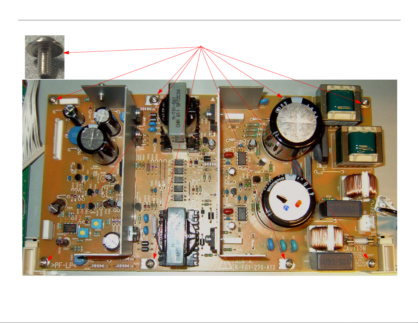
4. Remove 8 Screws, and lift out the Power Supply..
1. Remove 8 Screws
2. Lift out the Power Supply.
Pro 7880 / 9880 Field Repair Guide 12/20/07
Carriage Assembly Replacement Procedure Printer Component, Software Item, LCD Display, Printer Button Page 28.
Carriage Assembly Replacement Procedure
Required Parts: New Carriage, Part # 1291960 & Cutter Alignment tool, Part # 1212928
1. Unplug the Printer.
2. Raise both Ink Levers, closing the Ink Valves.
3. Remove the Top Cover, Left Side Cover, and Right Side Cover.
4. Release the Carriage Lock, and move the Carriage Mechanism to the center of the Printer.
5. Remove the Pump Cap Assembly.
6. Remove the Carriage Board Cover.
Loosen 1 Screw.
Lift off the Carriage Board Cover.

Pro 7880 / 9880 Field Repair Guide 12/20/07
Carriage Assembly Replacement Procedure Printer Component, Software Item, LCD Display, Printer Button Page 29.
7. Remove 2 Screws that fasten the Carriage Board Assembly.
8. Disconnect 5 Cables
Remove 2 Screws.
Disconnect 2 foil cables and 3 connectors.
Remove 1 screw that fastens the Ground Stra
p
Wire.
Pro 7880 / 9880 Field Repair Guide 12/20/07
Carriage Assembly Replacement Procedure Printer Component, Software Item, LCD Display, Printer Button Page 30.
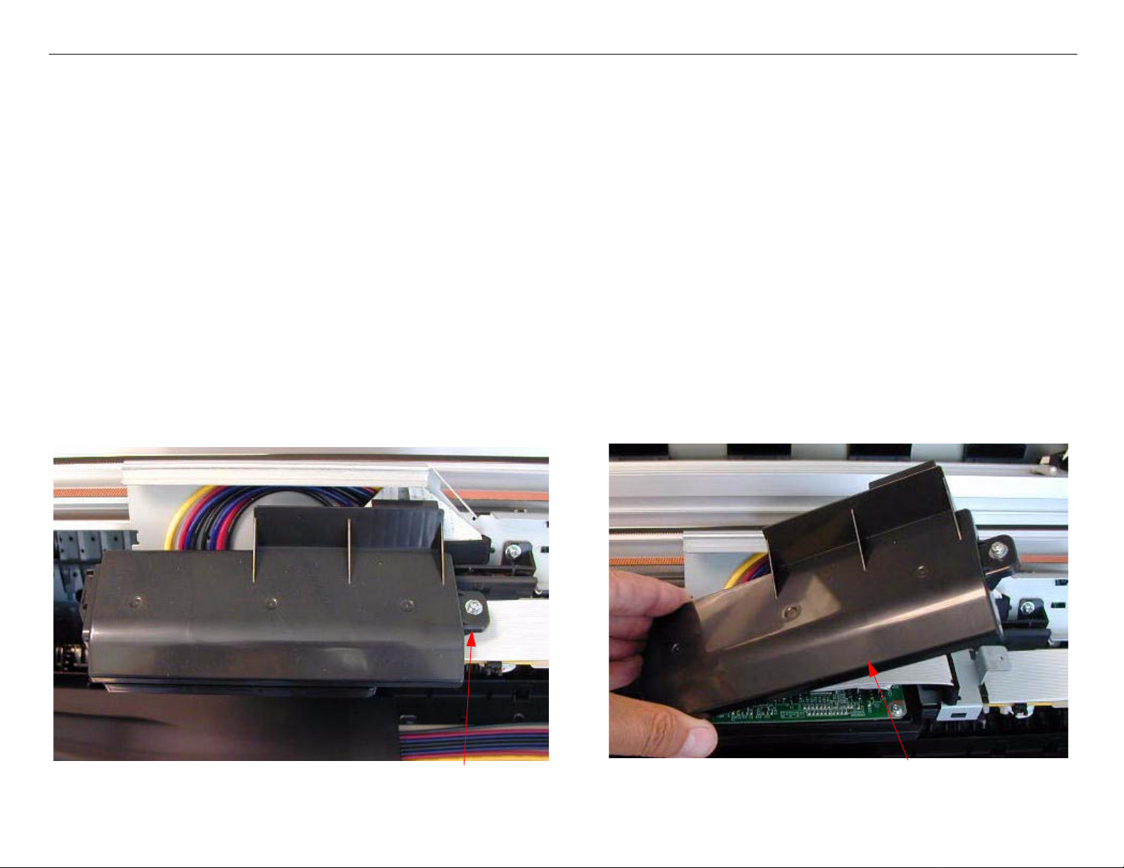
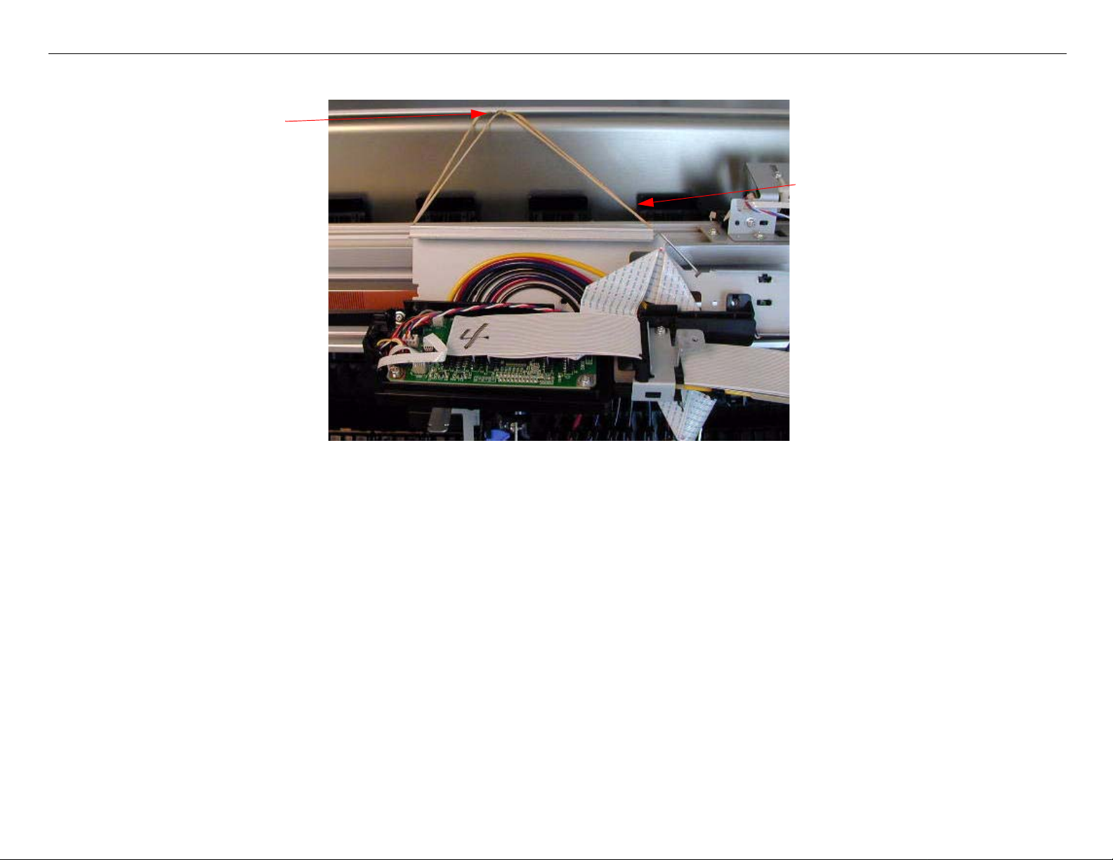
9. Lift and suspend the Carriage Board Assembly.
Loosen one of the Screws
that fasten a cover to support
the Carriage Board Assem-
bly.
Lift up the Carriage Board
Assembly, and suspend it
from the loosened Screw.
(Shown with rubber bands
in the picture).
Loading...