


 Loading...
SERVICE MANUAL
A4 Full Color Laser Printer
EPSON AcuLaser C2600/2600
SEPG04005
Notice:
All rights reserved. No part of this manual may be reproduced, stored in a retrieval system, or transmitted in any form or by any means, electronic, mechanical, photocopying, recording, or otherwise, without the prior written permission of SEIKO EPSON CORPORATION.
The contents of this manual are subject to change without notice.
All effort have been made to ensure the accuracy of the contents of this manual. However, should any errors be detected, SEIKO EPSON would greatly appreciate being informed of them.
The above not withstanding SEIKO EPSON CORPORATION can assume no responsibility for any errors in this manual or the consequences thereof. EPSON is a registered trademark of SEIKO EPSON CORPORATION.
General Notice: |
Other product names used herein are for identification purpose only and may be trademarks or registered trademarks of their |
|
respective owners. EPSON disclaims any and all rights in those marks. |
Copyright © 2005 SEIKO EPSON CORPORATION.
I&I CS/Quality Management & PL Department
PRECAUTIONS
Precautionary notations throughout the text are categorized relative to 1)Personal injury and 2) damage to equipment.
DANGER |
Signals a precaution which, if ignored, could result in serious or fatal personal injury. Great caution should be exercised in performing |
|
procedures preceded by DANGER Headings. |
WARNING |
Signals a precaution which, if ignored, could result in damage to equipment. |
The precautionary measures itemized below should always be observed when performing repair/maintenance procedures.
DANGER
1.ALWAYS DISCONNECT THE PRODUCT FROM THE POWER SOURCE AND PERIPHERAL DEVICES PERFORMING ANY MAINTENANCE OR REPAIR PROCEDURES.
2.NO WORK SHOULD BE PERFORMED ON THE UNIT BY PERSONS UNFAMILIAR WITH BASIC SAFETY MEASURES AS DICTATED FOR ALL ELECTRONICS TECHNICIANS IN THEIR LINE OF WORK.
3.WHEN PERFORMING TESTING AS DICTATED WITHIN THIS MANUAL, DO NOT CONNECT THE UNIT TO A POWER SOURCE UNTIL INSTRUCTED TO DO SO. WHEN THE POWER SUPPLY CABLE MUST BE CONNECTED, USE EXTREME CAUTION IN WORKING ON POWER SUPPLY AND OTHER ELECTRONIC COMPONENTS.
WARNING
1.REPAIRS ON EPSON PRODUCT SHOULD BE PERFORMED ONLY BY AN EPSON CERTIFIED REPAIR TECHNICIAN.
2.MAKE CERTAIN THAT THE SOURCE VOLTAGES IS THE SAME AS THE RATED VOLTAGE, LISTED ON THE SERIAL NUMBER/RATING PLATE. IF THE EPSON PRODUCT HAS A PRIMARY AC RATING DIFFERENT FROM AVAILABLE POWER SOURCE, DO NOT CONNECT IT TO THE POWER SOURCE.
3.ALWAYS VERIFY THAT THE EPSON PRODUCT HAS BEEN DISCONNECTED FROM THE POWER SOURCE BEFORE REMOVING OR REPLACING PRINTED CIRCUIT BOARDS AND/OR INDIVIDUAL CHIPS.
4.IN ORDER TO PROTECT SENSITIVE MICROPROCESSORS AND CIRCUITRY, USE STATIC DISCHARGE EQUIPMENT, SUCH AS ANTI-STATIC WRIST STRAPS, WHEN ACCESSING INTERNAL COMPONENTS.
5.REPLACE MALFUNCTIONING COMPONENTS ONLY WITH THOSE COMPONENTS BY THE MANUFACTURE; INTRODUCTION OF SECONDSOURCE ICs OR OTHER NON-APPROVED COMPONENTS MAY DAMAGE THE PRODUCT AND VOID ANY APPLICABLE EPSON WARRANTY.

About This Manual
This manual describes basic functions, theory of electrical and mechanical operations, maintenance and repair procedures of the printer. The instructions and procedures included herein are intended for the experienced repair technicians, and attention should be given to the precautions on the preceding page.
Manual Configuration |
Symbols Used in this Manual |
This manual consists of six chapters and Appendix.
CHAPTER 1.PRODUCT DESCRIPTIONS
Provides a general overview and specifications of the product.
CHAPTER 2.OPERATING PRINCIPLES
Describes the theory of electrical and mechanical operations of the product.
CHAPTER 3.TROUBLESHOOTING
Describes the step-by-step procedures for the troubleshooting.
CHAPTER 4.DISASSEMBLY / ASSEMBLY
Describes the step-by-step procedures for disassembling and assembling the product.
CHAPTER 5.ADJUSTMENT
Provides Epson-approved methods for adjustment.
CHAPTER 6.MAINTENANCE
Provides preventive maintenance procedures and the lists of Epsonapproved lubricants and adhesives required for servicing the product.
APPENDIX Provides the following additional information for reference:
•Connector pin assignments
•Electric circuit boards components layout
•Electrical circuit boards schematics
•Exploded diagram & Parts List
Various symbols are used throughout this manual either to provide additional information on a specific topic or to warn of possible danger present during a procedure or an action. Be aware of all symbols when they are used, and always read NOTE, CAUTION, or WARNING messages.
ADJUSTMENT |
Indicates an operating or maintenance procedure, practice or condition |
REQUIRED |
that is necessary to keep the product’s quality. |
|
|
CAUTION |
Indicates an operating or maintenance procedure, practice, or condition |
that, if not strictly observed, could result in damage to, or destruction of, |
|
|
equipment. |
CHECK |
May indicate an operating or maintenance procedure, practice or |
POINT |
condition that is necessary to accomplish a task efficiently. It may also |
|
provide additional information that is related to a specific subject, or |
|
comment on the results achieved through a previous action. |
WARNING |
Indicates an operating or maintenance procedure, practice or condition |
that, if not strictly observed, could result in injury or loss of life. |
|
|
Provides helpful tips and cautions on reassembly procedures, especially |
|
when incorrect reassembling may affect the print quality. |

General Precautions
To prevent possible accidents during maintenance work, strictly observe the servicing warnings and cautions described in this manual.
Power Supply
WARNING Before starting any service procedure, turn the printer power off and unplug the power cord from the wall outlet.
When the power supply cable must be connected, be aware of the potential for electrical shock and do all tasks by following the procedures in this manual.
Do not touch any live parts unless instructed to do so.
Make sure to ground the printer properly. Otherwise a short circuit may cause an electric fire or shock.
Handle the power cable with care observing the precautions listed below.
•Do not plug too many leads into a single socket.
•Do not damage or tamper with the power cable.
•Avoid putting heavy objects on the cable, plucking it, and bending it forcedly. To do so may damage the cable and cause an electric fire and shock.
•Do not insert or remove the power cable with wet hands to prevent electric shock.
•Never replace the fuse on the Power Supply Board (high pressure/low pressure) under any circumstances.
Mechanical Components
WARNING |
|
When servicing any driving assembly (e.g., gears), turn the power off and unplug the power cord to prevent injuries. |
|
|
|
|
Do not touch the driving part (e.g., gears) while the assembly (printer) is operating. |
|
|
|
|

High Temperature Assembly
WARNING When working with hot parts (Fuser Unit etc.), turn the power off and unplug the power cord to prevent burns or injuries. After unplugging the power cable, wait until the part or unit
cools down before starting maintenance work.
Make sure to wait the hot section to cool enough especially when accessing near the section immediately after printing.
HIGH TEMPERATURE
00000101
Laser Beam
WARNING Understand hazardous nature of the laser beam, use extreme caution to avoid injury of yourself and anyone around you. Letting a laser beam get directly into your eyes could result in loss of vision.
Since the laser beam has a narrower frequency band and more coherent phases than any other light (sunlight, electric light), the beam has excellent monochromaticity and convergence, thus it reaches long distances. Because of these characteristics, the laser beam converges into one point, causing high density and high temperature, which is harmful to the human body.
Never turn the interlock switch on forcibly while servicing to prevent the laser beam from |
|
emitting accidentally. The interlock switch is designed to be turned off when the cover D is |
|
opened. |
Cover D |
When performing maintenance work, be sure to turn the power off and unplug the power cord.
If you need to work on the printer with power applied, strictly follow the instructions in this manual.
Never disassemble the Laser Scanner Unit under any conditions.
Be sure to take off a wristwatch, ring or any other metal materials especially when working on the printer with the power applied.
00000201
Handling Parts
WARNING Be careful not to throw out your back when handling heavy parts while taking care not to drop those parts.
Always wear gloves to perform maintenance work since the printer has many sharp edges.
Do not work with wet or oily hands, or may cause you to drop parts or affect the function of the printer.
Use only specified genuine parts for maintenance.
Do not repair or replace the ICs and other electrical components on the power circuit board (including fuse) under any circumstances.
Handling Consumables
WARNING To avoid dust explosion or ignition, never bring any consumables close to flame or throw them into fire.
Take extra care not to inhale the developing powder (such as toner), and get it into your mouth and eyes. Use extreme caution to avoid injury of yourself and anyone around you.
Before starting your work, spread a sheet of paper over the working place to prevent interior of the product and the place becoming tainted.
If the developer or oil adheres to your skin or clothes, wipe it off thoroughly with dry rags before rinsing with water.
Do not disassemble the toner cartridges.
To prevent ignition, explosion, burn, injury, etc., do not use a general vacuum cleaner for cleaning dropped toner. (To do so may cause the toner to catch fire by sparks in the vacuum cleaner.)
00000301
Irregular Use of the Printer
WARNING Cautions when performing work with covers or parts removed
•As a general rule, do not power the printer while covers or parts are removed.
•If you need to remove covers or parts from the printer with power applied, take care of your fingers and clothes so as not to get entangled by moving parts such as the driving belt, gears, and fans.
Altering the printer is banned under any circumstances.

|
|
Revision Status |
|
|
|
Revision |
Date of Issue |
Description |
A |
APR. 28, 2005 |
First release |
|
|
|
|
|
|

EPSON AcuLaser C2600/2600 |
Revision A |
Contents
Chapter 1 Product Description
1.1 |
Overview ............................................................................................................. |
13 |
|
1.1.1 Engine Features .......................................................................................... |
13 |
|
1.1.2 Controller Features ..................................................................................... |
13 |
|
1.1.3 Software Features ....................................................................................... |
13 |
1.2 |
Basic Specifications............................................................................................ |
14 |
|
1.2.1 Process Specifications & System................................................................ |
14 |
|
1.2.2 Printer Basic Specifications........................................................................ |
14 |
1.3 |
Paper Specifications ............................................................................................ |
22 |
|
1.3.1 Paper Type .................................................................................................. |
22 |
|
1.3.2 Paper That May Cause Printing Defects, Paper Jams or Printer Malfunction. |
|
|
22 |
|
|
1.3.3 Paper Feed Types........................................................................................ |
23 |
|
1.3.4 Printing Area............................................................................................... |
23 |
1.4 |
Reliability and Serviceability .............................................................................. |
24 |
|
1.4.1 Reliability ................................................................................................... |
24 |
|
1.4.2 Durability.................................................................................................... |
25 |
|
1.4.3 Serviceability .............................................................................................. |
25 |
1.5 |
Service Conditions............................................................................................... |
26 |
|
1.5.1 Space Requirements.................................................................................... |
26 |
1.6 |
Conditions for Storage and Transport ................................................................. |
27 |
1.7 |
Electrical Characteristics ..................................................................................... |
28 |
1.8 |
Compatible Specification .................................................................................... |
29 |
1.9 |
Consumables/Periodic Replacement Unit ........................................................... |
30 |
|
1.9.1 Specifications.............................................................................................. |
30 |
|
1.9.2 Conditions for Storage and Transport......................................................... |
31 |
1.10 Maintenance ...................................................................................................... |
32 |
|
1.11 External Appearance and Unit Names .............................................................. |
33 |
|
|
1.11.1 Unit Names ............................................................................................... |
33 |
1.12 Engine Restrictions............................................................................................ |
34 |
|
|
1.12.1 Factors Limiting Printing Speed............................................................... |
34 |
|
1.12.2 Toner Duty Limiting Value ...................................................................... |
34 |
1.13 |
Notes When Replacing Consumables and Installing Optional Products .......... |
35 |
1.13.1 Consumables............................................................................................. |
35 |
|
1.13.2 Options...................................................................................................... |
35 |
|
1.14 |
Notes on Fuser Pressure .................................................................................... |
35 |
1.15 |
Life Details ........................................................................................................ |
36 |
1.16 |
Controller Specifications................................................................................... |
40 |
1.16.1 Controller Basic Specifications ................................................................ |
40 |
|
1.16.2 Controller Configuration .......................................................................... |
40 |
|
1.16.3 External Interface Specifications.............................................................. |
41 |
|
1.17 |
Control Panel..................................................................................................... |
43 |
1.17.1 External Appearance and Names.............................................................. |
43 |
|
1.17.2 Panel Settings List .................................................................................... |
45 |
|
1.17.3 Explanation of Menu and Settings............................................................ |
56 |
|
1.17.4 Special Operations.................................................................................... |
58 |
|
1.18 |
Printer Status ..................................................................................................... |
59 |
1.18.1 List of Printer Messages ........................................................................... |
59 |
|
1.18.2 Status Messages and Troubleshooting...................................................... |
61 |
|
1.18.3 Warning Messages and Troubleshooting ................................................. |
61 |
|
1.18.4 Error Messages and Troubleshooting ....................................................... |
62 |
|
1.18.5 Help Messages.......................................................................................... |
65 |
|
1.18.6 Service Call Error Messages..................................................................... |
71 |
|
1.19 Expanding the RAM.......................................................................................... |
73 |
|
1.20 |
Handling Precautions ........................................................................................ |
73 |
1.20.1 Precautions When Turning Off the Power ............................................... |
73 |
|
1.20.2 Precautions for High Temperature Parts .................................................. |
73 |
|
1.21 |
Status Sheet ....................................................................................................... |
74 |
1.22 |
Engine Status Sheet........................................................................................... |
77 |
1.23 |
Paper Handling Algorithm ................................................................................ |
78 |
1.24 |
Toner Check Sheet ............................................................................................ |
79 |
1.24.1 For Color Mode ........................................................................................ |
79 |
|
1.24.2 For 4xB/W Mode...................................................................................... |
79 |
|
1.25 |
Form Overlay List ............................................................................................. |
80 |
9

EPSON AcuLaser C2600/2600 |
Revision A |
1.26 Switching between Color Mode and Monochrome Mode ................................ |
81 |
1.26.1 Switching of Operation Mode .................................................................. |
81 |
1.26.2 Switching of Printer Driver ...................................................................... |
84 |
Chapter 2 Operating Principle
2.1 Print Process ........................................................................................................ |
86 |
2.1.1 Print Process Overview............................................................................... |
86 |
2.1.2 Print Process Diagram ................................................................................ |
87 |
2.1.3 Technical Explanation of Print Process...................................................... |
88 |
2.2 Paper Feed Mechanism...................................................................................... |
104 |
2.2.1 Main Unit Paper Feed Mechanism ........................................................... |
105 |
2.2.2 Duplex Printing......................................................................................... |
110 |
2.2.3 Paper Feed from Opt. Feeder Unit............................................................ |
111 |
2.3 Drive ................................................................................................................. |
112 |
2.3.1 Main Drive Motor..................................................................................... |
113 |
2.3.2 Photoconductor Drive Motor.................................................................... |
115 |
2.3.3 Rotary Drive Motor .................................................................................. |
115 |
2.3.4 Development Drive Motor........................................................................ |
116 |
2.3.5 Duplex Motor............................................................................................ |
117 |
2.3.6 Opt. Feeder Motor .................................................................................... |
118 |
2.4 Electrical............................................................................................................ |
119 |
2.4.1 Electronic Circuit Board / R/W Module................................................... |
119 |
2.4.2 Motor ........................................................................................................ |
120 |
2.4.3 Solenoids and Clutches............................................................................. |
121 |
2.4.4 Sensors and Switches................................................................................ |
122 |
2.4.5 Interlock Switch........................................................................................ |
123 |
2.4.6 Fan ............................................................................................................ |
124 |
2.5 Control............................................................................................................... |
125 |
2.5.1 Hardware for Control................................................................................ |
125 |
2.5.2 Image-Stabilizing Control ........................................................................ |
126 |
2.5.3 Operation Sequence .................................................................................. |
131 |
2.5.4 Operating Mode ........................................................................................ |
133 |
2.5.5 Control of Consumables and Components Needing Periodic Replacement ... |
|
134 |
|
2.6 Electrical Circuit Operation Principle ............................................................... |
136 |
2.6.1 Electric Circuit.......................................................................................... |
136 |
2.6.2 Engine Control Circuit.............................................................................. |
138 |
2.6.3 Controller.................................................................................................. |
140 |
Chapter 3 Troubleshooting |
|
|
3.1 |
Overview ........................................................................................................... |
142 |
|
3.1.1 Procedure Outline for Troubleshooting.................................................... |
142 |
|
3.1.2 Preliminary Check .................................................................................... |
142 |
|
3.1.3 Precautions in Performing Troubleshooting Work................................... |
143 |
|
3.1.4 Procedure for Troubleshooting................................................................. |
143 |
3.2 |
Troubleshooting for Paper Jam ......................................................................... |
144 |
3.3 |
Troubleshooting According to the Error Message ............................................ |
145 |
|
3.3.1 List of Error Message ............................................................................... |
145 |
|
3.3.2 List of Service Request............................................................................. |
145 |
|
3.3.3 Troubleshooting for Error Message.......................................................... |
147 |
|
3.3.4 Troubleshooting for Service Request Error.............................................. |
157 |
3.4 |
Printing-quality troubleshooting (PQT) ............................................................ |
184 |
|
3.4.1 Print Quality Trouble List......................................................................... |
184 |
|
3.4.2 Printing-quality troubleshooting............................................................... |
186 |
3.5 |
Test Print ........................................................................................................... |
208 |
Chapter 4 Disassembly and Assembly |
|
|
4.1 |
Overview ........................................................................................................... |
211 |
|
4.1.1 Precautions................................................................................................ |
212 |
|
4.1.2 Prohibited Disassembly ............................................................................ |
214 |
|
4.1.3 Tools ......................................................................................................... |
215 |
|
4.1.4 Inspection After Assembling.................................................................... |
215 |
4.2 |
Procedures for Disassembly and Assembly ...................................................... |
216 |
4.3 |
Disassembly and Reassembly ........................................................................... |
217 |
4.4 |
Disassembling Flowchart .................................................................................. |
219 |
4.5 |
Disassembling/Assembling the Main Unit........................................................ |
234 |
|
4.5.1 Consumables............................................................................................. |
234 |
|
4.5.2 Housing..................................................................................................... |
240 |
|
4.5.3 Paper Transport......................................................................................... |
253 |
|
4.5.4 Xerographic .............................................................................................. |
263 |
|
4.5.5 Exposure ................................................................................................... |
268 |
|
4.5.6 Deve.......................................................................................................... |
271 |
|
4.5.7 Transfer..................................................................................................... |
276 |
|
4.5.8 Fusing ....................................................................................................... |
293 |
|
4.5.9 Drive ......................................................................................................... |
294 |
|
4.5.10 Electrical................................................................................................. |
307 |
10
EPSON AcuLaser C2600/2600 |
Revision A |
|
4.5.11 MP Tray .................................................................................................. |
323 |
|
4.5.12 Paper Cassette......................................................................................... |
339 |
4.6 |
Disassembling/Assembling the Options............................................................ |
342 |
|
4.6.1 Opt. Feeder ............................................................................................... |
342 |
|
4.6.2 Duplex Unit .............................................................................................. |
355 |
Chapter 5 Adjustment |
|
|
5.1 |
Overview ........................................................................................................... |
365 |
|
5.1.1 Precautions................................................................................................ |
365 |
|
5.1.2 Reference Chapter .................................................................................... |
365 |
|
5.1.3 Adjustment Execution Timing.................................................................. |
366 |
5.2 |
Adjustment Program (LPssp) ............................................................................ |
367 |
|
5.2.1 Overview................................................................................................... |
367 |
|
5.2.2 Setup before Adjustment .......................................................................... |
367 |
|
5.2.3 Writing the model name ........................................................................... |
370 |
|
5.2.4 Writing USB ID........................................................................................ |
371 |
|
5.2.5 Counter Reset............................................................................................ |
372 |
|
5.2.6 Timing Adjustment................................................................................... |
373 |
|
5.2.7 Registration Adjustment (Top)................................................................. |
374 |
|
5.2.8 Registration Adjustment (Side) ................................................................ |
375 |
|
5.2.9 2nd Transfer Bias Adjustment .................................................................. |
376 |
|
5.2.10 Vpp Setting ............................................................................................. |
377 |
5.3 |
Firmware Update ............................................................................................... |
378 |
|
5.3.1 Main Controller Firmware Update ........................................................... |
379 |
|
5.3.2 Engine Controller Firmware Update ........................................................ |
381 |
Chapter 6 Maintenance |
|
|
6.1 |
Overview ........................................................................................................... |
385 |
6.2 |
Cleaning............................................................................................................. |
387 |
6.3 |
Maintenance Menu ............................................................................................ |
389 |
|
6.3.1 Entry into Maintenance Mode .................................................................. |
389 |
|
6.3.2 Maintenance Menu Items ......................................................................... |
390 |
6.4 |
Sheet for Servicing ............................................................................................ |
391 |
|
6.4.1 Engine Status Sheet .................................................................................. |
391 |
|
6.4.2 Print Log Report ....................................................................................... |
394 |
6.5 |
Consumables and Components That Need Periodic Replacement.................... |
396 |
|
6.5.1 Consumables............................................................................................. |
396 |
|
6.5.2 Regular Replacement Parts....................................................................... |
397 |
6.6 |
Gluing/Lubrication ............................................................................................ |
398 |
|
6.6.1 Gluing ....................................................................................................... |
398 |
|
6.6.2 Lubrication................................................................................................ |
398 |
Chapter 7 APPENDIX |
|
|
7.1 Connector Summary.......................................................................................... |
411 |
|
|
7.1.1 Connectors and Plug and Jack Layout...................................................... |
411 |
7.2 |
Wiring Connection Diagrams............................................................................ |
418 |
7.3 |
Parts List............................................................................................................ |
433 |
7.4 |
Exploded Diagrams ........................................................................................... |
437 |
7.5 |
Circuit Diagrams ............................................................................................... |
449 |
11

C H A P T E R
1
PRODUCT DESCRIPTION

EPSON AcuLaser C2600/2600 |
Revision A |
1.1 Overview
This printer is a non-impact color page printer that takes advantage of a laser and electrophotographic technologies.
It provides 600 dpi of resolution and 7.5 ppm (A4, color printing) or 30 ppm (A4, monochrome printing) of print speed.
1.1.1 Engine Features
High speed 4-cycle A4 engine
Table 1-1. Print Speed (When Printing A4)
|
Color printing |
Monochrome printing |
Simplex printing |
7.5 ppm |
30 ppm |
|
|
|
Duplex printing |
7.5 ppm |
20 ppm |
|
|
|
Two models: color and monochrome
The monochrome model has one black toner cartridge bundled as standard. Adding three black toner cartridges (option) allows the printer to print up to 20,000 copies. Furthermore, the monochrome model can be upgraded to color model.
The color model can be operated as monochrome model by replacing the color toners with black ones or removing them.
Compact and light weight, suitable for desktop placement
Dimension |
435 mm (W) x 516 mm (D) x 425 mm (H) |
|
|
Weight |
35 kg |
|
|
Paper supply (Maximum of 1150 sheets, 3-bin paper feed is possible)
Paper cassette
Standard |
MP Tray |
150 sheets |
|
|
|
||
Lower paper cassette |
500 sheets |
||
|
|||
Option |
Paper cassette unit |
500 sheets |
|
|
|
|
|
|
Maximum |
1150 sheets |
|
|
|
|
Paper eject capacity is 250 sheets, face-down only.
1.1.2 Controller Features
High speed intelligent controller
CPU: |
VR5532A (350 MHz) |
RAM
Standard RAM: 64 MB
Expanded RAM: 512 MB (When two 256 MB DIMMs are installed.)
Support for optional large capacity, 40 GB HDD.
Color technology
nPGI, which allows low price, high quality printing
Wide LCD panel with backlight
The new wide LCD panel supporting a maximum of 22 digits and 5 lines (132 x 65 dots) provides improved operation and visibility.
Improved serviceability with the addition of the Help function (with description and graphics).
Interface
USB interface (Rev. 2.0 HS, Supports bi-directional (D4))
Network interface (10Base-T/100Base-TX)
Parallel interface (IEEE1284)
Type-B interface
1.1.3 Software Features
Adobe PostScript 3 (17 fonts), PCL6 (monochrome) as standard ESC/Page Color, PCL5e, FX, LQ, and IBM emulations are also provided
Printer status and printer environment monitor with use of bi-directional EJL and MIB
Version upgrade function for engine program ROM
Support for DCC command (DIAG command only)
Support for firmware overwrite using RCC (full or partial overwrite)
Support for manual duplex
Product Description |
Overview |
13 |

EPSON AcuLaser C2600/2600 |
Revision A |
1.2 |
Basic Specifications |
|
1.2.1 |
Process Specifications & System |
|
Printing method: |
Semiconductor laser beam scan and |
|
|
|
electrophotography with dry single component system. |
Exposure light source: |
Semiconductor laser |
|
Photoconductor: |
Organic photoconductor |
|
Charging: |
Wire electrode scorotron |
|
Development: |
1-component non-contact development system |
|
Toner: |
1-component non-magnetic toner |
|
Primary transfer: |
Intermediate transfer belt method |
|
Fixing: |
Roller heat fixing system |
|
1.2.2 Printer Basic Specifications
RESOLUTION
600 x 600 dpi
WARMING UP TIME
120 V: 80 seconds or less (at 23 °C, 55 % RH, rated voltage)
230 V: 80 seconds or less (at 23 °C, 55 % RH, rated voltage)
OPERATION MODE
This engine supports the following operation modes.
B/W mode: |
Supports Toner cartridge K x 1 |
4xB/W mode: |
Supports Toner cartridge K x 4 |
Color mode: |
Supports Toner cartridges Y x 1, M x 1, C x 1, and K x 1. |
|
|
PRINT MODE |
|
Color mode: |
Color mode using Y, M, C, K toner (color mode only) |
Monochrome mode: Normal black and white mode, enabling printing at the highest speed of the main unit.
PRINTING SPEED MODE
Std. mode (plain paper 1): Makes prints at the maximum speed of the engine.
Std. mode (plain paper 2): This mode is to make prints on papers with less
fixability (such as bond papers) at the maximum speed of the engine. As the fuser unit takes a substantial amount of time to increase its temperature for fixing toner onto the papers firmly, the first print time becomes slow. When it comes to a continuous printing, however, the printing can be performed at the maximum speed of the engine.
Low speed mode 1: |
Slows down the speed of printing on papers with |
|
thickness of 90 g/m2 (24 lb) or more to sustain the |
|
fixability. |
Low speed mode 2: |
Slows down the speed of printing on envelopes for the |
|
better fixability or on transparents for the stable |
|
permeability. |
Product Description |
Basic Specifications |
14 |

EPSON AcuLaser C2600/2600 |
Revision A |
FIRST PRINT TIME
The following table shows the time from receiving a start command to when trailing edge of the paper leaves the paper eject roller. Note that the time given in the tables does not apply when the printer is in the conditions described in “1.12 Engine Restrictions” (p.34).
Monochrome mode*1
Table 1-2. Monochrome Mode (Unit: Seconds or Less)
Paper |
|
Simplex printing |
|
Duplex printing |
|||
Std. mode |
Std. mode |
Low speed |
Low speed |
Std. mode |
Std. mode |
||
size |
|||||||
|
(Plain paper 1) |
(Plain paper 2*2) |
mode 1 |
mode 2 |
(Plain paper 1) |
(Plain paper 2*2) |
|
A4 |
9.3 |
19.3 |
17.9 |
26.6 |
13.3 |
23.3 |
|
|
|
|
|
|
|
|
|
A5 |
8.9 |
18.9 |
17.1 |
25.0 |
12.9 |
22.9 |
|
B5 |
9.1 |
19.1 |
17.6 |
25.9 |
13.1 |
23.1 |
|
|
|
|
|
|
|
|
|
LT |
9.2 |
19.2 |
17.8 |
26.3 |
13.2 |
23.2 |
|
EXE |
9.2 |
19.2 |
17.7 |
26.1 |
13.2 |
23.2 |
|
|
|
|
|
|
|
|
|
Color mode*1
Table 1-3. Color Mode (Unit: Seconds or Less)
Paper |
Simplex printing |
|
Duplex printing |
||||
|
|||||||
Std. mode |
|
|
Std. mode |
Std. mode |
|||
size |
|
Std. mode |
Low speed |
Low speed |
|||
|
|
(Plain paper 1) |
(Plain paper 2*2) |
mode 1 |
mode 2 |
(Plain paper 1) |
(Plain paper 2*2) |
A4 |
|
15.3 |
25.3 |
23.9 |
32.6 |
23.3 |
33.3 |
|
|
|
|
|
|
|
|
A5 |
|
14.9 |
24.9 |
23.1 |
31.0 |
22.9 |
32.9 |
B5 |
|
15.1 |
25.1 |
23.6 |
31.9 |
23.1 |
33.1 |
|
|
|
|
|
|
|
|
LT |
|
15.2 |
25.2 |
23.8 |
32.3 |
23.2 |
33.2 |
EXE |
|
15.2 |
25.2 |
23.7 |
32.1 |
23.2 |
33.2 |
|
|
|
|
|
|
|
|
Note |
*1: The above speed are the same for any paper feeder including the option cassette. |
|
|||||
*2: The mode to be used for papers that are hardly fixed.
As the temperature for the fixation is set higher than that of the other modes, it takes relatively long period of time until the temp. reaches the required level.
CONTINUOUS PRINTING SPEED
This excludes operations that fall under the restrictions on printing speed explained in “1.12 Engine Restrictions” (p.34).
Monochrome mode
Table 1-4. Monochrome Mode (Unit: PPM)
|
|
|
Simplex printing |
|
Duplex printing |
|
|
|
|
||
Paper size |
|
Std. mode |
Low speed mode 1 Low speed mode 2 |
Std. mode |
|
|
|
(Plain paper 1, 2) |
(Plain paper 1, 2) |
||
|
|
|
|
|
|
A4, B5, LT |
|
30 |
4.2 |
2.6 |
20 |
|
|
|
|
|
|
A5, EXE |
|
30 |
4.2 |
2.6 |
20 |
Envelope C6, |
|
|
|
|
|
MON, DL, C5, |
|
– |
– |
2.6 |
– |
Com-#10 |
|
|
|
|
|
|
|
|
|
|
|
User defined size |
|
30 |
4.2 |
2.6 |
– |
Color mode |
|
|
|
|
|
|
|
Table 1-5. Color Mode (Unit: PPM) |
|
||
|
|
|
|
|
|
|
|
|
Simplex printing |
|
Duplex printing |
Paper size |
|
Std. mode |
Low speed mode 1 Low speed mode 2 |
Std. mode |
|
|
|
(Plain paper 1, 2) |
(Plain paper 1, 2) |
||
|
|
|
|
|
|
A4, B5, LT |
|
7.5 |
2.9 |
2.1 |
7.5 |
|
|
|
|
|
|
A5, EXE |
|
7.5 |
2.9 |
2.1 |
7.5 |
Envelope C6, |
|
|
|
|
|
MON, DL, C5, |
|
– |
– |
2.1 |
– |
Com-#10 |
|
|
|
|
|
|
|
|
|
|
|
User defined size |
|
7.5 |
2.9 |
2.1 |
– |
|
|
|
|
|
|
PAPER FEED REFERENCE
Center-line reference for each paper size and for both MP tray and 500-sheet cassette (optional).
Product Description |
Basic Specifications |
15 |

EPSON AcuLaser C2600/2600 |
Revision A |
PAPER FEED
Table 1-6. Paper Feed
|
Paper feed |
Sheet capacity |
Paper type/Paper size |
Acceptable paper |
|
|
Height capacity |
basis weight* |
|||
|
|
|
|||
|
|
150 sheets |
Standard paper: |
82 g/m2 |
|
|
|
EPSON high quality plain paper |
|||
|
|
|
|
||
|
|
|
|
|
|
|
|
16.5 mm |
Plain paper/recycled paper: |
64 to 90 g/m2 |
|
|
|
A4, A5, B5, LT, GLT, HLT, EXE |
|||
|
|
|
|
||
|
|
60 sheets |
Transparency: A4, LT |
– |
|
|
|
|
|
|
|
|
|
50 sheets |
Labels: A4, LT |
– |
|
|
MP tray |
EPSON coated papers: A4 |
|||
|
|
|
|||
Standard |
75 sheets |
Thick Paper: |
91 to 163 g/m2 |
||
|
|||||
|
A4, A5, B5, LT, GLT, HLT, EXE |
||||
|
|
||||
|
|
|
|
||
|
|
|
|
|
|
|
|
15 sheets |
Envelopes: |
– |
|
|
|
C5, C6, Com-#10, DL, Monarch, |
|||
|
|
|
ISO-B5 |
|
|
|
|
16.5 mm |
User defined size: |
64 to 163 g/m2 |
|
|
|
Width 98 to 216/ Length 148 to 297 |
|||
|
|
|
|
||
|
|
|
|
|
|
|
Lower paper |
500 sheets |
Standard paper: |
82 g/m2 |
|
|
EPSON high quality plain paper |
||||
|
cassette (C1) |
|
|
||
|
55 mm |
Plain paper: A4, LT |
64 to 90 g/m2 |
||
|
|
||||
|
Paper |
500 sheets |
Standard paper: |
82 g/m2 |
|
Option |
cassette unit |
|
EPSON high quality plain paper |
|
|
|
(C2) |
55 mm |
Plain paper: A4, LT |
64 to 90 g/m2 |
|
|
Duplex |
– |
A4, LT, B5, A5, EXE |
64 to 90 g/m2 |
|
Note |
*: Refer to |
“1.3 Paper Specifications” (p.22). |
|
||
OPTIONAL PAPER SOURCE COMBINATION
Installing an optional paper cassette unit enables the printer to load the maximum number of papers as shown in the table below.
Table 1-7. Optional Paper Source Combination
|
Combination |
|
(1) |
(2) |
|
|
|
||||
|
|
|
|
|
|
Standard |
MP tray |
150 sheets* |
{ |
{ |
|
|
|
|
|
||
Lower paper cassette (C1) |
500 sheets* |
{ |
{ |
||
|
|||||
Option |
Paper cassette unit (C2) |
500 sheets* |
– |
{ |
|
|
|
|
|
|
|
|
Total number of sheets |
|
650 sheets |
1150 sheets |
|
|
|
|
|
|
Note *: Standard paper: EPSON high quality plain paper (82 g/m2)
Product Description |
Basic Specifications |
16 |

EPSON AcuLaser C2600/2600 |
Revision A |
SUPPORTED PAPER SIZE, TYPE AND ORIENTATION
Supported paper
Table 1-8. List of Supported Paper Size, Type and Orientation
|
|
Paper |
Paper size Dimensions in mm (inches) |
MP tray |
Standard lower |
Optional paper |
Paper orientation |
Duplex printing |
||
|
|
Vertical (length) |
Horizontal (width) |
paper cassette |
cassette unit |
|||||
|
|
|
|
|
|
|
||||
|
A4 |
|
|
297.00 |
210.00 |
{ |
{ |
{ |
SEF |
{ |
|
|
|
|
|
|
|
|
|
|
|
|
A5 |
|
|
210.00 |
148.00 |
{ |
– |
– |
SEF |
{ |
Standard |
JIS-B5 |
|
|
257.00 |
182.00 |
{ |
– |
– |
SEF |
{ |
|
|
|
|
|
|
|
|
|
|
|
LT |
|
|
279.40 (11.00") |
215.90 (8.50") |
{ |
{ |
{ |
SEF |
{ |
|
|
|
|
||||||||
|
HLT |
|
|
215.90 (8.50") |
139.70 (5.50") |
{ |
– |
– |
SEF |
– |
|
|
|
|
|
|
|
|
|
|
|
|
GLT |
|
|
266.70 (10.50") |
203.20 (8.00") |
{ |
– |
– |
SEF |
– |
|
EXE |
|
|
266.70 (10.50") |
184.15 (7.25") |
{ |
– |
– |
SEF |
{ |
|
|
|
|
|
|
|
|
|
|
|
|
User defined paper size |
148.00 to 297.00 |
98.00 to 216.00 |
{ |
– |
– |
Free |
– |
||
|
Transparency |
A4: 297.00 |
A4: 210.00 |
{ |
– |
– |
SEF |
– |
||
|
|
|
|
|
|
|
|
|||
|
LT: 279.40 |
LT: 215.90 |
{ |
– |
– |
SEF |
– |
|||
|
|
|
|
|||||||
|
Labels |
|
|
A4: 297.00 |
A4: 210.00 |
{ |
– |
– |
SEF |
– |
|
|
|
|
|
|
|
|
|
|
|
paper |
|
|
LT: 279.40 |
LT: 215.90 |
{ |
– |
– |
SEF |
– |
|
|
|
|
||||||||
|
|
MONARCH |
190.50 (7 1/2) |
98.43 (3 7/8) |
{ |
– |
– |
SEF |
– |
|
Special |
Envelopes |
|
|
|
|
|
|
|
|
|
|
Com-#10 |
241.30 (9 1/2) |
104.78 (4 1/8) |
{ |
– |
– |
SEF |
– |
||
|
|
|
||||||||
|
|
|
DL |
220.00 |
110.00 |
{ |
– |
– |
SEF |
– |
|
|
|
|
|
|
|
|
|
|
|
|
|
|
C5 |
229.00 |
162.00 |
{ |
– |
– |
SEF |
– |
|
|
|
C6 |
162.00 |
114.00 |
{ |
– |
– |
SEF |
– |
|
|
|
|
|
|
|
|
|
|
|
|
|
|
ISO-B5 |
250.00 |
176.00 |
{ |
– |
– |
SEF |
– |
Note |
1: SEF (Short Edge Feed): Set paper to be loaded from its short side. |
|
|
|
|
|
||||
2:The supported sizes differ depending on the destination.
3:For the orientation of envelopes, refer to “Envelope orientation” (p.18).
4:Curls must be straightened.
Product Description |
Basic Specifications |
17 |
EPSON AcuLaser C2600/2600 |
Revision A |
Paper orientation
Paper Feed |
|
MP Tray |
|
Cassette (C1/C2) |
||
|
|
|
|
|
|
|
Paper Orientation/ |
|
Place Print Side Down. |
|
|
Place Print Side Up. |
|
Feeding Direction |
|
|
|
|
|
|
|
|
|
|
|
|
|
|
|
|
|
|
|
|
Envelope orientation
Feeding Direction |
|
|
|
|
|
|
|
|
|
||
|
|
|
|
01000201 |
|
|
01000101 |
||||
|
|
|
|
|
|
Envelope Types |
MONARCH, DL, |
C5 |
|||
Com- #10, C6 |
|||||
|
|
||||
|
|
|
|
|
|
NOTE 1: Place papers in the MP tray with the printable side face down.
2:When the flap is closed, printing on the reverse (flap side) is not available.
(The flap may adhere to the transfer belt and open, which may result in paper wrinkles and paper jams.)
3:Only envelopes without tape or glue can be used.
4:Change the fuser unit lever when printing envelopes.
(For details, refer to “1.14 Notes on Fuser Pressure” (p.35).)
5:Only envelopes with trapezoid shaped flaps can be fed with the flap opened.
Envelopes with triangular shaped flaps should not be used. (It may cause a slip off or stack defect.)
PAPER EJECT
Only for face-down (FD) 250 sheets
NOTE: Standard paper: EPSON high quality plain paper (82 g/m2)
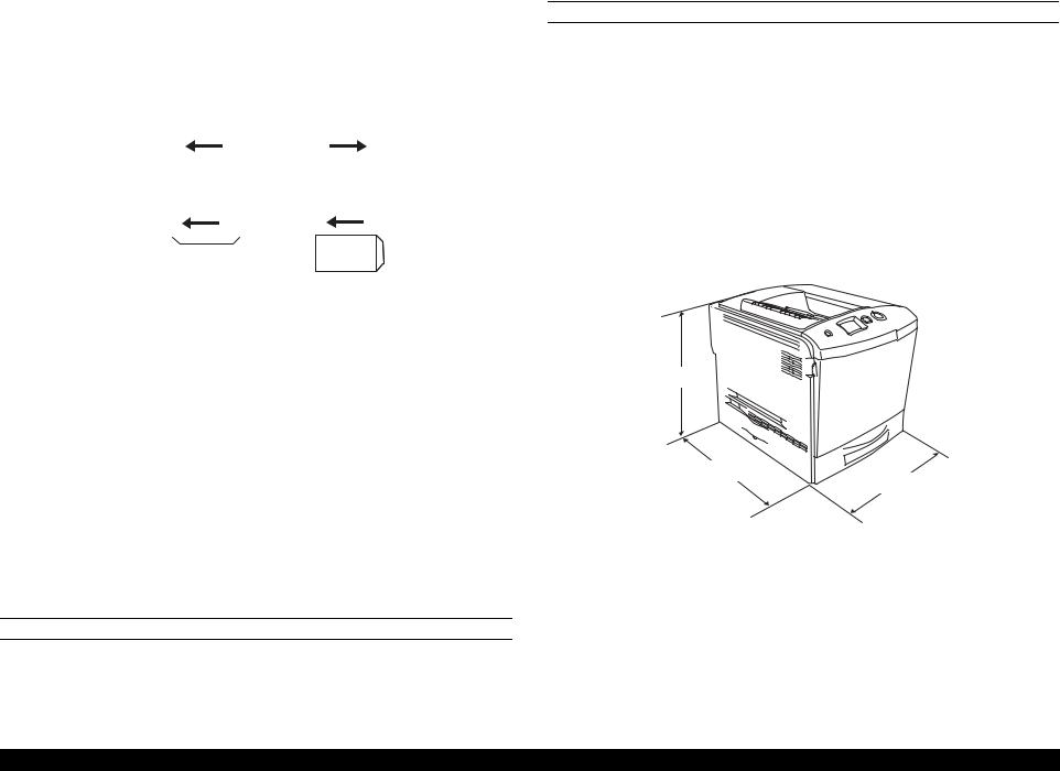
DIMENSIONS AND WEIGHT
Stand alone outline dimensions and weight
Table 1-9. Stand Alone Outline Dimensions and Weight
|
Width (mm) |
Depth (mm) |
Height (mm) |
Weight (kg) |
|
||||
|
|
|
|
|
Main unit |
431 |
518 |
425 |
37*1 / 33*2 |
500-sheet cassette unit (option) |
408 |
482 |
140 |
5 |
Duplex unit (option) |
132 |
282 |
220 |
0.9 |
|
|
|
|
|
Note : Manufacturing tolerance is ± 5 mm in dimensions and ± 0.5 kg in weight. Note *1: Includes consumables.
*2: Initial condition (exc. Toner Cartridges)
425 mm
518 mm
431 mm
01000301
Figure 1-1. Dimensions (Main Unit)
Product Description |
Basic Specifications |
18 |
EPSON AcuLaser C2600/2600 |
Revision A |
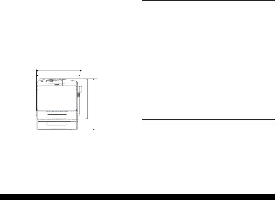
Outline dimensions and weight with options installed
Table 1-10. Outline Dimensions and Weight With Options Installed
|
|
Width (mm) |
Depth (mm) Height (mm) |
Weight (kg) |
||
|
|
|||||
|
|
|
|
|
|
|
Main unit + Optional paper cassette |
431 |
518 |
538 |
42* |
||
unit |
|
|||||
|
|
|
|
|
||
|
|
|
|
|
||
Main unit + Duplex unit |
447 |
518 |
425 |
38* |
||
Main unit + Optional paper cassette |
447 |
518 |
538 |
43* |
||
unit + Duplex unit |
||||||
|
|
|
|
|||
|
|
|
|
|
|
|
Note : |
Manufacturing tolerance is ± 5 mm in dimensions and ± 0.5 kg in weight. |
|||||
Note *: |
Includes consumables. |
|
|
|
|
|
447 mm |
431 mm |
425 mm |
mm |
|
538 |
|
|
|
|
01000401
Figure 1-2. Dimensions (Including Options)
CONSUMABLES AND PERIODIC REPLACEMENT UNIT
Table 1-11. List of Consumables and Periodic Replacement Unit
Classification |
Replacement unit |
|
|
|
|
|
Toner cartridge (Black, Cyan, Yellow, Magenta) |
|
|
|
|
|
Photoconductor unit |
|
Consumables |
Fuser unit |
|
|
|
|
|
Waste toner collector |
|
|
Filter |
|
|
|
|
|
Transfer belt unit (TRANSFER, Assy; ASP) |
|
|
Cleaning tape (MOUNTING PLATE, ANTI-STATIC; ASP) |
|
|
|
|
|
Cleaner clutch (CLUTCH, CLEANER) |
|
Periodic replacement units |
2nd transfer clutch (CLUTCH, 2ND TRANSFER) |
|
|
|
|
|
Paper eject roller (COVER Assy., FU; ASP) |
|
|
Post-fixing roller (COVER Assy., FU; ASP) |
|
|
|
|
|
Pickup roller (ROLLER ASSY, PICK UP) |
|
|
|
NOTE: For detailed specifications, refer to “1.9 Consumables/Periodic Replacement Unit” (p.30).
POWER SUPPLY
Power supply operating voltage/frequency
AC 110 V to 120 V ± 10 %, 50 Hz / 60 Hz ± 3 Hz
AC 220 V to 240 V ± 10 %, 50 Hz / 60 Hz ± 3 Hz
Power supply for the controller
DC 5.0 V ± 5 %, 2A
DC 3.3 V ± 5 %, 5A
Product Description |
Basic Specifications |
19 |

EPSON AcuLaser C2600/2600 |
Revision A |
POWER CONSUMPTION
The maximum rated current is measured with all engine options and controller options installed.
Table 1-12. List of Power Consumption
|
|
|
120V |
230V |
|
Maximum rated current |
10 A or less |
6 A or less |
|||
|
|
|
|
|
|
consumption |
Maximum |
880 W |
900 W |
||
Continuous printing average |
Color |
335 W |
332 W |
||
|
|||||
|
|
|
|
||
|
Monochrome |
567 W |
583 W |
||
|
|
||||
Power |
Average during standby with the heater on |
96 W |
99 W |
||
|
|
|
|
||
Sleep mode* |
10 W or less |
12 W or less |
|||
|
|||||
|
Power supply off |
0 W |
0 W |
||
|
|
|
|
|
|
Note *: Refer to “Table 1-13. Operating State” (p.20).
CONSUMPTION CURRENT
500-sheet cassette unit (option)
5 V / 0.3 A or less
24 V / 0.35 A or less
Duplex unit (option)
5 V / 0.1 A or less
24 V / 1.0 A or less
OPERATING STATE
This printer operates in the following 3 operating states.
|
|
|
Table 1-13. Operating State |
|
|
|
|
|
|
|
Operational mode |
|
|
Explanation |
|
Operating state |
Performs a print job in various printing mode upon receiving a command |
||
|
from the controller. |
|||
|
|
|||
|
|
|
|
|
|
|
Standby state. Switches to this mode automatically after completing a |
||
|
Standby state |
print job (exits out of the operating state) without receiving any |
||
|
|
commands. |
||
|
|
Switches to this mode on receiving a command from the controller. |
||
|
Sleep state |
Supporting BAM and International Energy Star Program (power |
||
|
|
consumption 21W or less within 30 minutes after the printing operation) |
||
|
|
|
|
|
|
|
|
|
|
|
PRODUCT LIFETIME |
|
|
|
|
|
|
Table 1-14. Product Lifetime |
|
|
|
|
|
|
|
|
|
|
Product lifetime |
|
Main unit |
|
|
300,000 pages (color*1) or 600,000 pages (monochrome)*2 or |
|
|
|
5 years; whichever comes first. |
|
|
|
|
|
|
|
|
|
|
|
|
Optional paper cassette unit |
|
400,000 pages*3 |
|
|
Duplex unit |
|
|
600,000 pages*4 |
Note *1: 1,200,000 pages for single color images
*2: 480,000 pages when the ratio of color and monochrome is 1:1 (1,200,000 images) *3: 2/3 of the main unit max pages (Monochrome 600,000 pages)
*4: When all of the main unit max pages (Monochrome 600,000 pages) are made by duplexing.
Product Description |
Basic Specifications |
20 |
EPSON AcuLaser C2600/2600 |
Revision A |
NOISE
Sound pressure
Table 1-15. Sound Pressure
|
|
Operating state |
Standby state |
Sleep state |
|
|
|
||||
|
|
|
|
|
|
Main unit |
Color mode |
56 dB (A) |
40 dB (A) |
Background noise |
|
Monochrome mode |
56 dB (A) |
40 dB (A) |
|||
|
|
||||
Note : Reference values |
|
|
|
||
Sound power |
|
|
|
||
|
|
Table 1-16. Sound Power |
|
||
|
|
|
|
|
|
|
|
Operating state |
Standby state |
Sleep state |
|
|
|
|
|
|
|
Main unit |
Color mode |
68 dB (A)* |
52 dB (A) |
|
|
|
|
|
|
||
Monochrome mode |
66 dB (A)* |
52 dB (A) |
Background noise |
||
With all optional installations |
Exceeds the main |
|
|||
|
|
||||
unit values by less |
52 dB (A) |
|
|||
(reference value) |
|
||||
than 1 db |
|
|
|||
|
|
|
|
||
|
|
|
|
|
|
Note *: The method of measuring and calculation conforms to ISO-7779 and ISO-9296. (Employing standard values for RAL-UZ85 (BAM standard))
Note : (A) indicates that the value has been adjusted with consideration of human sensitivity to frequencies (correction by A characteristic).
EXHAUST GAS
|
Table 1-17. Exhaust Gas |
|
|
|
Value |
Ozone Concentration |
0.02 mg/m3 or less (the measuring method conforms to BAM) |
Styrene Concentration |
0.07 mg/m3 or less (the measuring method conforms to BAM) |
Fine Particles Concentration |
0.075 mg/m3 or less (the measuring method conforms to BAM) |
TVOC |
0.40 mg/m3 or less |
Product Description |
Basic Specifications |
21 |

EPSON AcuLaser C2600/2600 |
Revision A |
1.3 Paper Specifications
1.3.1 Paper Type
Standard paper
RX-80 paper (Monochrome), 4024 paper (20 lb) (Monochrome), EPSON high quality plain paper (A4)
Plain paper
64 g/m2 to 90 g/m2 (17 lb to 24 lb)
(General purpose copy papers and recycled papers.)
Recommended recycled paper: Recommended Recycling Copy classic
Special paper
EPSON transparency sheets (A4, LT)
Labels
Thick papers (91 g/m2 to 163 g/m2)
Envelopes (75 g/m2 to 105 g/m2)
EPSON coated papers (A4) (Guarantees only the paper feedability)
CHECK |
|
lb: |
Ream weight = Total weigh of 500 sheets of 17" x 22" |
POINT |
|
|
sized paper |
|
|
g/m2: 1 g/m2 = 0.2659763 lb |
|
|
Before purchasing a large amount of paper, test the paper if it |
||
|
|
can be printed normally. |
|
|
|
|
|
1.3.2Paper That May Cause Printing Defects, Paper Jams or Printer Malfunction
Transfer paper (carbon paper, non-carbon paper), thermal paper, impact paper, acid paper
Paper that is too thin or too thick
Paper that is wet or damp
Paper with special coatings or color printer paper with processed surfaces
Glossy (too slick) paper, or paper with too rough surface
Paper that the roughness is significantly different by side
Paper with punch holes or perforations
Creased, curled or torn paper
Irregularly shaped paper or paper with non-perpendicular corners
Labels that peel off easily
Paper with glue, staples or paper clips attached to it
Special paper for ink jet applications (super-fine, glossy, glossy film, etc.)
Paper previously used in a thermal or ink jet printer
Transparencies for other color laser printers or color photocopiers
Paper that has been already printed with other color/monochrome laser printers or photocopiers
Sheets of paper stuck together
Postcards for ink jet printers, unofficial postcards, and adhesive postcards
Iron print coated paper (for both ink jet and laser printers)
Paper that is deteriorated or discolored, due to temperatures lower than 235 ºC.
Product Description |
Paper Specifications |
22 |
EPSON AcuLaser C2600/2600 |
Revision A |
1.3.3 Paper Feed Types
Table 1-18. Paper Feed Types
|
|
|
|
|
Special paper |
|
||
|
Feeder |
Standard |
Plain |
|
|
Thick |
|
|
|
paper |
paper |
Transpar- |
Labels |
paper, |
Envelopes |
||
|
|
|||||||
|
|
|
|
ency |
Coated |
|||
|
|
|
|
|
|
|||
|
|
|
|
|
|
paper |
|
|
Standard |
MP tray |
{ |
|
|
|
|
|
|
|
|
|
|
|
|
|
||
Paper |
{ |
|
X |
X |
X |
X |
||
|
||||||||
|
cassette |
|||||||
|
|
|
|
|
|
|
||
Option |
Paper |
{ |
|
X |
X |
X |
X |
|
cassette unit |
||||||||
|
|
|
|
|
|
|||
|
|
|
|
|
|
|
||
|
|
|
|
|
|
|
|
|
|
Duplex unit |
{ |
|
X |
X |
X |
X |
|
Note : |
|
|
|
|
|
|
||
{ : Paper feed and image quality is guaranteed.
: Paper feed and printing is possible. However, this is limited to types of paper for general applications. Image quality is not guaranteed.
X : Paper feed is impossible.
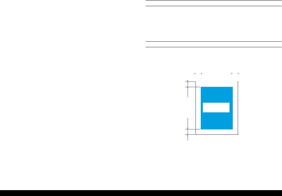
1.3.4 Printing Area
MAXIMUM PRINTABLE AREA
208 mm (width) x 289 mm (length)
NOTE: Although papers smaller than the maximum printable size can be printed without margins, continuous printing on such papers, especially if the left, right, top, and bottom margins beyond the paper exceed 4 mm, causes contamination inside the printer and paper jam.
GUARANTEED PRINTING AREA
The guaranteed printing area is shown below. The minimum left, right, top and bottom margins are 4 mm for any type of paper.
4 mm |
|
|
|
|
|
|
|
|
4 mm |
|||
|
|
|
|
|
|
|
|
|
|
|
|
|
|
|
|
|
|
|
|
|
|
|
|
|
|
|
|
|
|
|
|
|
|
|
|
|
|
|
|
|
|
|
|
|
|
|
|
|
|
|
|
4 mm
Guaranteed
Printing Area
4 mm
01000501
Figure 1-3. Guaranteed Printing Area
Product Description |
Paper Specifications |
23 |

EPSON AcuLaser C2600/2600 |
Revision A |
1.4 Reliability and Serviceability
1.4.1 Reliability
MPBF/MTBF
60,000 pages or more*1 / 3,000 hours or more*2
NOTE *1: Assuming the ratio of color and monochrome is 1:1
*2: Assuming an average power-on time is 300 hours per month.
PAPER FEED RELIABILITY
Jam rate
Table 1-19. Jam Rate
|
|
Paper Type |
|
||
Reliability issue |
Environment A*1 |
Environment B*2 |
|||
|
Simplex printing |
Duplex printing |
Simplex printing |
Duplex printing |
|
|
|
|
|
|
|
Standard paper |
1/4000 sheets or |
2/4000 sheets or |
3/4000 sheets or |
6/4000 sheets or |
|
less |
less |
less |
less |
||
|
|||||
|
|
|
|
|
|
Plain paper |
1/2000 sheets or |
2/2000 sheets or |
3/2000 sheets or |
6/2000 sheets or |
|
less |
less |
less |
less |
||
|
|||||
Special paper |
1/100 sheets or |
– |
3/100 sheets or |
– |
|
less |
less |
||||
|
|
|
|||
|
|
|
|
|
|
Paper feed error / multiple sheet feeding*3 / paper wrinkles / creased corner rate*4
Table 1-20. Paper Feed Error/Multiple Sheet Feeding/
Paper Wrinkles/Creased Corner Rate
|
|
|
|
Paper Type |
|
|
Reliability issue |
|
Environment A*1 |
Environment B*2 |
|||
|
|
Simplex printing |
Duplex printing |
Simplex printing |
Duplex printing |
|
|
|
|
|
|
|
|
Standard paper |
1/1000 sheets or |
2/1000 sheets or |
3/1000 sheets or |
6/1000 sheets or |
||
less |
|
less |
less |
less |
||
|
|
|
||||
|
|
|
|
|
|
|
Plain paper |
|
1/500 sheets or |
2/500 sheets or |
3/500 sheets or |
6/500 sheets or |
|
|
less |
|
less |
less |
less |
|
|
|
|
||||
Special paper |
|
1/25 sheets or less |
– |
3/25 sheets or less |
– |
|
|
|
|
|
|
||
Note *1: Conditions for environment A (15 to 28 °C / 35 to 70 % RH) |
|
|||||
|
Paper size: |
Standard-size |
|
|
||
|
Humidity control: no regulation |
|
|
|||
*2: Conditions for environment B (10 to 30 °C / 15 to 65, 85 % RH) |
|
|||||
|
Paper size: |
Standard-size |
|
|
||
Humidity control: uncontrolled packed papers
*3: The multiple sheet feeding rate does not include the performance at the boundary of the originally loaded papers and additionally replenished papers.
*4: Counts creases more than C1 mm.
Product Description |
Reliability and Serviceability |
24 |
EPSON AcuLaser C2600/2600 |
Revision A |
PRINTING START POSITION ACCURACY
Table 1-21. Printing Start Position Accuracy
|
A4/A3 |
|
|
Simplex printing |
Duplex printing |
||||||||||
Main scanning direction Reference point (c) |
|
|
± 2.0 mm |
± 3.0 mm |
|||||||||||
Sub-scanning direction Reference point (a) |
|
|
± 2.5 mm |
± 2.5 mm |
|||||||||||
|
|
|
|
|
|
|
|
|
|
|
|
|
|
|
|
|
|
|
c |
a |
|
b |
|
|
|
|
|
|
|
||
|
|
|
|
|
|
|
|
|
|
|
|
|
|
|
|
|
|
|
|
|
|
|
|
|
|
|
|
|
|
||
|
|
|
|
|
|
|
|
|
|
f |
DirectionFeed |
|
|
|
|
|
|
|
|
|
|
Printable Area |
|
|
|
|
|
|
|
||
|
|
|
|
|
|
|
|
|
|
|
|
|
|
|
|
|
|
|
d |
|
|
|
|
|
|
|
|
|
|
||
|
|
|
|
|
|
|
|
|
|
|
|
|
|||
|
|
|
|
|
|
|
|
|
|
|
|
|
|
|
|
|
|
|
|
|
|
|
|
|
|
|
|
|
|
|
|
|
|
|
|
|
|
e |
|
01000601 |
|
||||||
|
|
|
|
|
|
|
|
|
|||||||
|
Figure 1-4. Printing Start Position Accuracy |
||||||||||||||
|
|
|
|
|
|
|
|
|
|
|
|
|
|
|
|
SKEW |
|
|
|
|
|
|
|
|
|
|
|||||
|
|
|
|
|
|
Table 1-22. Skew |
|
|
|||||||
|
|
|
|
|
|
|
|
|
|
|
|
|
|
|
|
|
|
|
A4 |
|
|
Simplex printing |
Duplex printing |
|
|||||||
|
Main scanning direction (| a-b |) |
|
|
1.47 mm |
2.21 mm |
|
|||||||||
|
|
|
|
|
|
|
|
|
|
|
|
|
|
|
|
|
Sub-scanning direction (| c-d |) |
|
|
2.05 mm |
3.07 mm |
|
|||||||||
|
Table 1-23. Length Standard of Measurement |
|
|||||||||||||
|
|
|
|
|
|
|
|
|
|
|
|
|
|
|
|
|
|
|
|
|
|
|
|
|
|
|
|
|
|
A4 |
|
|
Simplex printing |
|
|
Main scanning direction (e) |
208 mm |
|
|||||||||
|
Duplex printing |
|
|
Sub-scanning direction (f) |
289 mm |
|
|||||||||
|
|
|
|
|
|
|
|
|
|
|
|
|
|
|
|
HEIGHT OF CURL ON OUTPUT PAPER
Table 1-24. Height of Curl on Output Paper
Paper type |
Height of Curl |
Standard paper, Plain paper |
30 mm or less |
|
|
Transparency |
15 mm or less |
Other special papers |
No regulation |
|
|
Note 1: The same for simplex and duplex printing
2:Measurement conditions:
Image occupation rate 5 % misaligned monochrome printing, or color printing with 5 % of each color (total 20 %).
Print 10 sheets of 1p/J intermittent printing, then measure after an interval of 1 minute.
Differs in accordance with the image occupation rate/array pattern printing conditions.
1.4.2Durability
PRINT VOLUME
Average: 8,000 pages/month*1
Maximum: 48,000 pages/month (Color mode)*2
120,000 pages/month (Monochrome mode)*3
NOTE *1: Product lifetime 480,000 pages assuming the ratio of color and monochrome printing is 1:1; 5 years assuming the usage is 8,000 page/months.
*2: The ratio of color and monochrome printing is 1:1 Color printing only:30,000 pages/month
*3: 6,000 pages (MaxPV/day) x 20 days
1.4.3 Serviceability
MTTR
Average 30 minutes or less
The MTTR value indicated above represents the time for service personnel to locate and correct the malfunction only, and the time for examining malfunction is not included.
Product Description |
Reliability and Serviceability |
25 |
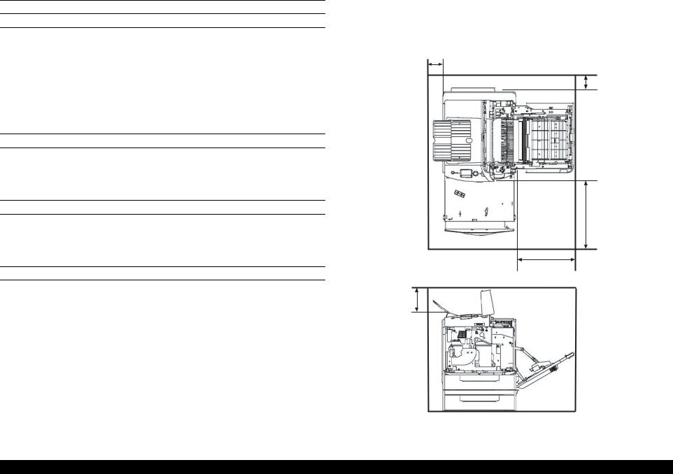
EPSON AcuLaser C2600/2600 |
Revision A |
1.5 Service Conditions
AMBIENT TEMPERATURE AND HUMIDITY
Table 1-25. Ambient Temperature and Humidity
|
Temperature (ºC) |
Humidity (%RH) |
Other |
|
Operating |
10 to 35 |
15 to 85 |
No condensation allowed |
|
|
|
|
||
Non-operating |
0 to 35 |
10 to 85 |
||
|
||||
|
|
|
|
AIR PRESSURE (ALTITUDE)
76 kPa or more (2,500 m or less)
LEVELNESS
Difference between front and back or left and right should be 1 º or less
ILLUMINATION
3,000 lx or less (do not expose to direct sunlight)
1.5.1 Space Requirements
In order to ensure that the printer operates properly, provide at least as much space as shown in the diagram below.
100
100
430
330
130
Unit: mm
01000701
Figure 1-5. Space Requirements
Product Description |
Service Conditions |
26 |

EPSON AcuLaser C2600/2600 |
Revision A |
1.6 Conditions for Storage and Transport
AMBIENT TEMPERATURE AND HUMIDITY CONDITIONS
Table 1-26. Ambient Temperature and Humidity Conditions
Condition |
Temperature (°C) |
Humidity (%RH) |
Guarantee |
|||
(No condensation allowed) |
period |
|||||
|
|
|
||||
Normal conditions |
|
0 to 35 |
|
15 to 80 |
12 months after |
|
|
|
manufacture |
||||
|
|
|
|
|
||
|
|
|
|
|
|
|
Harsh conditions |
High |
35 to 40 |
High |
80 to 95 |
Maximum of |
|
Low |
-20 to 0 |
Low |
5 to 15 |
one month |
||
|
||||||
|
|
|
|
|
|
|
RESISTANCE TO AIR PRESSURE (ALTITUDE)
0 to 2,500 m
(However, this is not applicable when pressurized to 70.9275 kPa or more during air transportation.)
DROPPING
No damage with 1 corner, 3 edges, and 6 sides dropping when packed. Conforms to divisional Assessment Standard of Transport (T-AE-05-001).
Table 1-27. Dropping
Dropping height |
Package weight |
|
(referential) |
||
|
||
|
|
Standard |
Main unit |
42 cm |
45.4 kg |
|
Option |
Duplex unit |
82 cm |
1.7 kg |
|
500-sheet cassette unit |
82 cm |
6.8 kg |
||
|
||||
|
|
|
|
VIBRATION
No damage under the following conditions
Conforms to divisional Assessment Standard of Transport (T-AE-05-001).
Frequency |
5 to 55 Hz |
|
|
Acceleration |
1.5 G |
(However, constant 7.5 mm double amplitude is assumed between 5 |
|
|
and 10 Hz.) |
Direction of application |
XYZ 3 directions |
|
|
Frequency sweep |
Logarithmic sweep 10 minutes one way. |
Number of cycles |
3 cycles for each direction (1 hour each) |
|
|
COMPRESSION
Conforms to divisional Assessment Standard of Transport (T-AE-05-001).
Product Description |
Conditions for Storage and Transport |
27 |

EPSON AcuLaser C2600/2600 |
Revision A |
1.7 Electrical Characteristics
NOTE: The following sections do not include any optional units.
ELECTRICAL FAST TRANSIENT /BURSTS (AC LINE NOISE)
Ensure the following conditions using evaluation methods compliant with IEC61000- 4-4.
1 kV: No errors excluding insignificant dot errors
2 kV: No damage to parts
INSTANTANEOUS OUTAGES
No effect on printing quality.
DIP: 1 cycle 100 % (at -10 % of rated current)
RESISTANCE TO STATIC ELECTRICITY
Ensure the following conditions using evaluation methods compliant with IEC61000- 4-2 and CISPR 24.
Contact electric discharge 4.5 kV: No error on any device after applying
Aerial electric discharge 8.5 kV: No error on any device after applying
INRUSH CURRENT
100 A and 1/2 cycles or less for a cold start in an atmosphere at 23 ºC or more.
INSULATION RESISTANCE
10 MΩ or more
WITHSTAND VOLTAGE
No dielectric break down during application of the voltages shown below for a one minute period.
Table 1-28. Withstand Voltage
Model Type |
Between primary and secondary |
Between power supply line and |
|
supply transformers |
chassis |
||
|
|||
|
|
|
|
120 V |
AC 1250 V |
AC 1000 V |
|
|
|
|
|
230 V |
AC 1500 V |
AC 3000 V |
|
|
|
|
LEAK CURRENT
120 V: 0.25 mA or less
230 V: 3.5 mA or less
Product Description |
Electrical Characteristics |
28 |

EPSON AcuLaser C2600/2600 |
Revision A |
1.8 Compatible Specification
SAFETY STANDARD
|
Table 1-29. Safety Standards |
|
|
|
|
Model Type |
Applicable Standards |
|
120 V |
UL60950 3rd Edition |
|
CSA C22.2 No.60950 |
||
|
||
|
|
|
230 V |
IEC60950 3rd Edition |
|
|
|
SAFETY STANDARD (LASER TRANSMISSION)
Table 1-30. Safety Standards (Laser Transmission)
|
Model Type |
Applicable Standards |
|
120 V |
FDA21CFR Chapter 1, Subchapter J, Section 1010, 1040 |
|
|
|
|
200 V series |
Compliant with IEC60825-1 |
|
|
|
Note : Refer to the Laser Specification |
||
Wave length: |
770-800 nm |
|
Maximum output rating: 15 mW
EMI STANDARDS
|
Table 1-31. EMI Standards |
|
|
|
|
Model Type |
Applicable Standards |
|
120 V |
FCC Part 15 Subpart B, Class B |
|
|
|
|
230 V |
EN55022 (CIRSPR Publication 22), Class B |
|
EN61000-3-2 (Harmonics) Class A |
||
|
||
|
|
ELECTRICAL POWER HIGH FREQUENCY
230V: |
EN61000-3-3 (Flicker) |
POWER CONSUMPTION
Conforms to International Energy Star Program standards
MISCELLANEOUS
Toner: |
Have no affect on the human body (conforms to OSHA, |
|
TSCA, EINECS) |
OPC: |
Have no affect on the human body (conforms to OSHA) |
Ozone generation: |
Conforms to UL478 5th edition |
Materials: |
Does not contain any materials prohibited in each country, |
|
nor harmful substances above the permitted values |
Product Description |
Compatible Specification |
29 |

EPSON AcuLaser C2600/2600 |
Revision A |
1.9 Consumables/Periodic Replacement Unit
CAUTION The print page-based service life values of the Consumables and Periodical Replacement Parts are guidelines. The number of
printable pages changes depending on how they are printed. The number of printable pages decreases depending on the intermittent
printing (where a few pages, one to several pages, are printed each time), paper size, paper orientation, thick paper printing, printed document, frequent power-on/off, etc. Hence, the number of printable pages of the consumables and periodical replacement parts may become less than a half depending on the operating conditions and environment of the user.
1.9.1 Specifications
Consumables (replaced by the user)
Table 1-32. Consumables
Name |
Configuration |
Lifetime |
External |
Weight |
|
(pages) |
dimensions |
(kg) |
|||
|
|
(mm) |
|||
|
|
|
|
||
Toner cartridge (K) |
|
5,000*1 |
|
0.9 |
|
(developer cartridge) |
|
|
|||
|
|
|
|
||
|
|
|
336 (W) |
|
|
Toner cartridge (C) |
Development, |
2,000*1 |
0.8 |
||
82 (D) |
|||||
Toner cartridge (M) |
Toner hopper |
|
|
||
|
67 (H) |
|
|||
Toner cartridge (Y) |
|
|
|
||
|
|
|
|
||
(developer cartridge) |
|
5,000*1 |
|
0.9 |
|
|
|
|
|
|
|
Photoconductor unit |
Waste toner |
Monochrome: |
378 (W) |
|
|
collection space |
40,000 |
|
|||
(a Waste toner collector and a filter |
111 (D) |
1.3 |
|||
integrated drum |
|
||||
unit are included in the package) |
Color: 10,000 |
159 (H) |
|
||
cartridge |
|
||||
|
|
|
|
||
Waste toner collector*2 |
|
Monochrome: |
256 (W) |
|
|
Waste toner tank |
60,000 |
50 (D) |
0.2 |
||
(A filter is included in the package) |
|||||
|
Color: 15,000 |
225 (H) |
|
||
|
|
|
|||
|
Toner filter |
|
327 (W) |
|
|
Filter*2 |
15, 000 |
37 (D) |
0.1 |
||
Ozone filter |
|||||
|
|
46 (H) |
|
||
|
|
|
|
||
Fuser unit (120V) |
Fuser |
80,000 |
394 (W) |
2.3 |
|
|
|
|
113 (D) |
|
|
Fuser unit (230V) |
Fuser |
80,000 |
2.3 |
||
140 (H) |
|||||
|
|
|
|
||
|
|
|
|
|
Note *1: Approximate number of printed pages using A4 continuous printing at 5 % image occupation rate.
The cartridge lifetime varies according to the paper size and type of printing (toner save mode etc.).
*2: Replaced at the same time as photoconductor unit or the Waste toner collector.
Note : For details on the part life, see “1.15 Life Details” (p.36).
Product Description |
Consumables/Periodic Replacement Unit |
30 |
Loading...