


EWM10931 TC1
SERVICE MANUAL
WASHING
Washing machines
guide to diagnostics of
electronic controls
EWM10931
THE INSPIRATION
RANGE
TC3 / TC2 / TC1
© ELECTROLUX HOME PRODUCTS
Customer Care - EMEA
Training and Operations Support
Technical Support
Publication
number
599 75 27-46
Edition: 04/2012 - Rev. 00
EN

Guide to diagnostics of electronic controls EWM10931
2012 TS/DT-mdm FCPD-dp 2/79 599 75 27-46 Rev.00

Guide to diagnostics of electronic controls EWM10931
2012 TS/DT-mdm FCPD-dp 3/79 599 75 27-46 Rev.00
Index
1
INTRODUCTION .................................................................................................................................. 5
1.1 Purpose of this manual .................................................................................................................. 5
1.2 Cautions ........................................................................................................................................ 5
1.3 How to proceed ............................................................................................................................. 6
2 WM APPLIANCE CONTROL PANELS ................................................................................................. 7
3 PROGRAMMING/UPDATING THE MAIN CIRCUIT BOARD ................................................................. 7
4 DIAGNOSTICS SYSTEM ..................................................................................................................... 8
4.1 Accessing diagnostics ................................................................................................................... 8
4.2 Quitting the diagnostics system ..................................................................................................... 8
4.3 Phases of the diagnostics test ....................................................................................................... 9
4.3.1 TC3-TC2 styling .................................................................................................................... 9
4.3.2 TC1 styling .......................................................................................................................... 11
5 ALARMS ............................................................................................................................................ 13
5.1 Displaying the alarms to the user ................................................................................................. 13
5.2 Reading the alarms ..................................................................................................................... 14
5.2.1 TC3-TC2 styling .................................................................................................................. 14
5.2.2 TC1 styling .......................................................................................................................... 14
5.3 Rapid reading of alarms ............................................................................................................... 14
5.4 Deleting the last alarm ................................................................................................................. 15
5.5 ALARM SUMMARY TABLE ......................................................................................................... 16
5.6 Notes on the behaviour of certain alarms ..................................................................................... 20
6 CANNOT ACCESS THE DIAGNOSTICS PROGRAMME .................................................................... 21
6.1 None of the LEDs on the circuit board light up ............................................................................. 21
7 TROUBLESHOOTING BASED ON ALARM CODES .......................................................................... 22
E11: Water fill difficulty during washing ............................................................................................ 22
E13: Water leaks ............................................................................................................................. 24
E21: Drain difficulty ......................................................................................................................... 26
E23: Problems with the component (triac) controlling the drain pump .............................................. 28
E24: Sensing circuit of the component (triac) controlling the drain pump faulty................................. 30
E31: The analogue pressure switch provides the main circuit board with a signal outside the limits. 30
E32: The analogue pressure switch causes an error during calibration ............................................ 31
E35: Water level too high ................................................................................................................ 32
E38: Internal pressure chamber is clogged ...................................................................................... 33
E41: Door open (device with 4 connections) .................................................................................... 34
E42: Problems opening door (device with 4 connections) ................................................................ 36
E43: Problems with the component (triac) controlling the door delay system (device with
4 connections) ........................................................................................................................ 38
E44: Door closed “sensing” circuit faulty .......................................................................................... 39
E45: Problems with the “sensing” circuit of the component (triac) controlling the door delay system . 39
E52: No signal from the motor tachimetric generator (1
st
part) ......................................................... 40
E52: No signal from the motor tachimetric generator (2
nd
part) ......................................................... 42
E57: Inverter is drawing more than 16A current ............................................................................... 44
E58: Inverter is drawing more than 4A current ................................................................................. 46
E59: No signal from the tachometric generator ................................................................................ 48
E5A: Overheating on Inverter board heat dissipator ......................................................................... 50
E5C: The Inverter board input voltage is too high (beyond 430 V) .................................................... 51
E5d: Data transfer error between Inverter board and main circuit board ........................................... 52
E5E: Communication error between Inverter board and main circuit board ...................................... 53
E5F: Inverter board fails to start the motor ....................................................................................... 53
E5H: The Inverter board input voltage is too low (less than 175 V) .................................................. 54
E62: Overheating during washing .................................................................................................... 55
E66: Heating element power supply relay faulty .............................................................................. 56
E68: Washing heating element leakage ........................................................................................... 57
E69: Washing heating element damaged ........................................................................................ 58
E6A: Heating relay sensing faulty .................................................................................................... 59
E6H: Heating element power relay faulty (incongruence between sensing and relay status) ............ 59
E71: Washing NTC probe faulty ...................................................................................................... 60
E74: NTC probe improperly positioned ............................................................................................ 61
E83: Error reading the programme selector code............................................................................. 62
E86: Programme selector configuration error................................................................................... 62
E87: Display board microprocessor faulty ........................................................................................ 62
E91: Communication error between the display board and the main circuit board (1
st
part) .............. 63

Guide to diagnostics of electronic controls EWM10931
2012 TS/DT-mdm FCPD-dp 4/79 599 75 27-46 Rev.00
E91: Communication error between the display board and the main circuit board (2
nd
part) ............. 64
E91: Communication error between the display board and the main circuit board (3
rd
part) .............. 65
E92: protocol incongruence ............................................................................................................. 66
E93: Appliance configuration error................................................................................................... 66
E94: Incorrect configuration of washing cycle .................................................................................. 66
E97: Inconsistency between control selector version and configuration data .................................... 66
E98: Communication error between main PCB and Inverter board .................................................. 66
E9C: Display board configuration error ............................................................................................ 67
E9E: Display board sensor/touch key faulty ..................................................................................... 67
EC1: Water fill solenoid valves blocked ........................................................................................... 68
EC2: Problem with weight sensor .................................................................................................... 69
EC3: Problem with weight sensor .................................................................................................... 70
EF1: Drain hose blocked/kinked/too high; drain filter clogged/dirty ................................................... 71
EF2: Excessive detergent dosing; drain hose kinked/blocked; drain filter dirty/clogged ................... 71
EF3: Aqua Control device triggered ................................................................................................. 71
EF4: Water fill pressure too low and solenoid valve open ................................................................ 71
EF5: Unbalanced load, spin phases skipped. .................................................................................. 71
EF6: Reset appliance. ..................................................................................................................... 72
EH1: Mains frequency incorrect ....................................................................................................... 72
EH2: Supply voltage too high .......................................................................................................... 72
EH3: Supply voltage too low ............................................................................................................ 73
EH4: “zero watt” relay not functioning .............................................................................................. 73
EHE: Inconsistency between safety relay (main circuit board) and safety sensing circuit ................. 73
EHF: Safety sensing circuit faulty .................................................................................................... 73
8 WM OPERATING CIRCUIT DIAGRAM ............................................................................................... 74
8.1 Key to circuit diagram WM ........................................................................................................... 75
8.2 Main circuit board connectors ...................................................................................................... 76
8.3 Burns on the main circuit board EWM10931 ................................................................................ 77
Guide to diagnostics of electronic controls EWM10931
2012 TS/DT-mdm FCPD-dp 5/79 599 75 27-46 Rev.00
1 INTRODUCTION
1.1 Purpose of this manual
The purpose of this manual is to explain, simply and schematically, the steps any Technician must take
when faced with the problems indicated by the various alarm codes on appliances with electronic control in
the EWM10931 TC1-TC2-TC3 THE INSPIRATION RANGE.
Depending on the appliance configuration, the alarms may be entirely or partially displayed to the user: the
latter solution is usually adopted.
The diagnostics system is used by Service Technicians to:
♦ Read alarms
♦ delete the alarm stored,
♦ Test the appliance operation.
1.2 Cautions
Any work on electrical appliances must only be carried out by qualified personnel.
Before servicing an appliance, check the efficiency of the electrical system in the
home using appropriate instruments. For example: refer to the indications
provided/illustrated in the <<metratester>> course at the address
(http://electrolux.edvantage.net
) on the Electrolux Learning Gateway portal.
When the work is finished check that the equipment's safety conditions have
been reinstated, as though it were straight off the assembly line.
If the circuit board has to be handled/replaced, use the ESD kit (Cod. 405 50 63-95/4)
to avoid static electricity from damaging the circuit board, see S.B. No. 599 72 08-09
or consult the course “Electrostatic charges” at the address
(http://electrolux.edvantage.net
) on the Electrolux Learning Gateway portal.
This platform is not fitted with an ON/OFF switch. Before you access internal
components, take the plug out of the socket to cut the power supply.
Make resistance measurements, rather than direct voltage and current
measurements.
Warning the sensors located on the display board could be at a potential of
220 Volts.
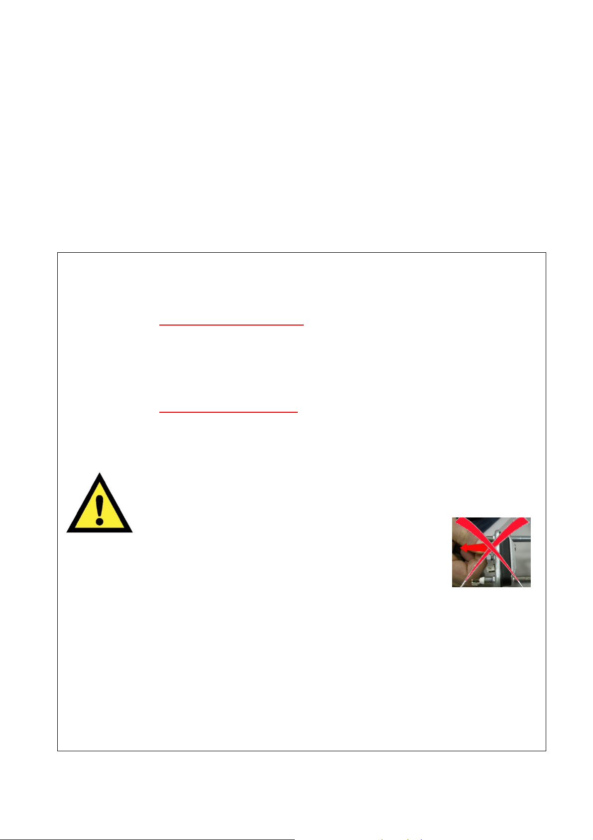
When replacing the heating element, replace it with one
that has the same characteristics (2 thermal fuses) in order
not to compromise the safety of the appliance. Do not
remove/switch the NTC sensors between heating elements.
Always empty the appliance of all the water before laying it
on its side.
Never place the appliance on its right side (electronic control system side):
some of the water in the detergent dispenser could leak onto the
electrical/electronic components and cause these to burn.
When replacing components, please refer to the code shown in the list of spare
parts relating to the appliance.
The resistance values of the components shown in this S.M. are purely
indicative (relating to a sample appliance with new components).
For the actual value of the component, please refer:
to S.B. 599706597 for motors, and for the other components, please consult
S.M. 599728903 “Component Characteristics”.

Guide to diagnostics of electronic controls EWM10931
2012 TS/DT-mdm FCPD-dp 6/79 599 75 27-46 Rev.00
1.3 How to proceed
1. Identify the type of control in question (page 7) and access the diagnostic cycle. (see page 8)
2. Read the alarm stored (page 14) and consult the instructions regarding the “alarm codes”, page 16÷19
3. Delete the alarms stored (page 15)
4. If you are unable to access the diagnostic mode, consult the chapter entitled “The diagnostics system
cannot be accessed” (page 21)
5. Should the main electronic circuit board need to be replaced, make sure there are no burns. (see page 77)
6. After all interventions, check the appliance is operating correctly using the diagnostic cycle. (page 9)
7. Delete any alarm that may have been stored during the diagnostics operations (page 15)
Guide to diagnostics of electronic controls EWM10931
2012 TS/DT-mdm FCPD-dp 7/79 599 75 27-46 Rev.00
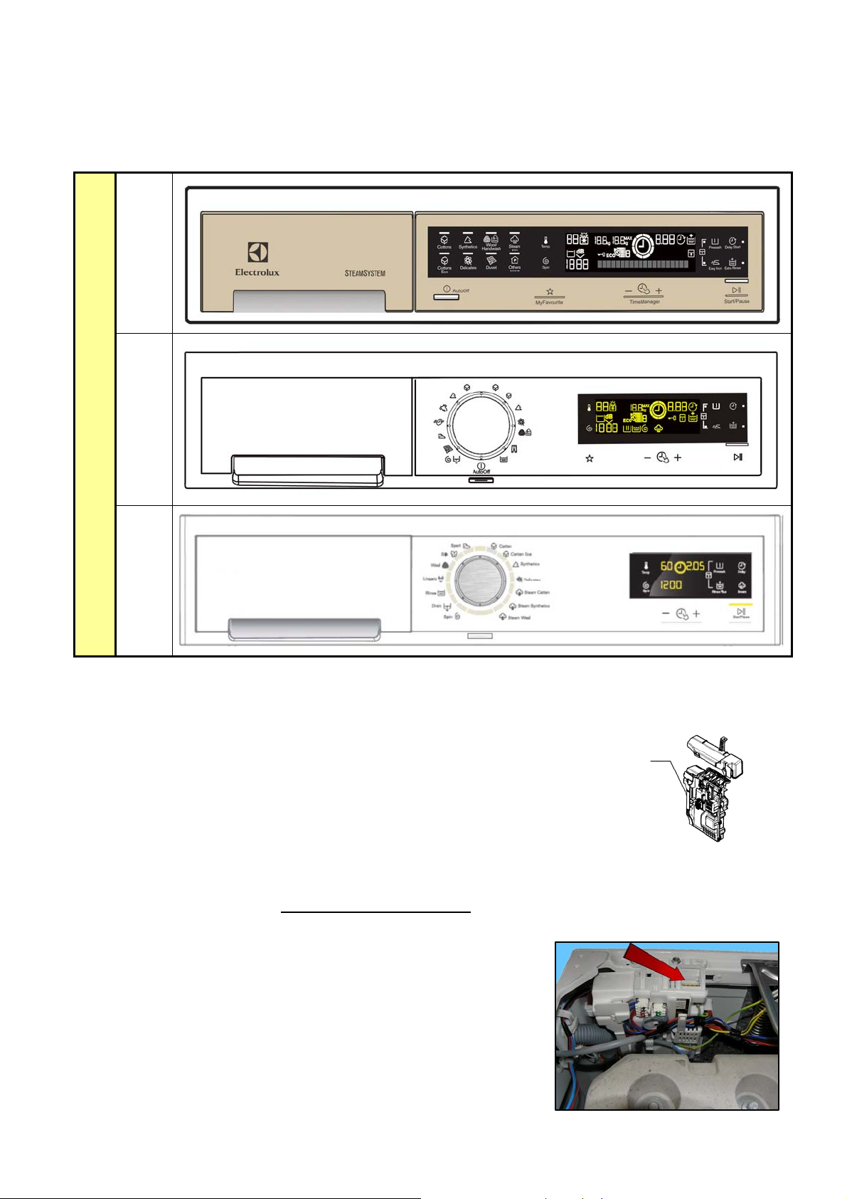
2 WM APPLIANCE CONTROL PANELS
These are the stylings available at the time of printing of this Service Manual. Others may be developed
in future.
3 PROGRAMMING/UPDATING THE MAIN CIRCUIT BOARD
In the Service Notes the main circuit board (587) is identified with two spare parts
codes:
ª Code 973 914… identifies the pre-programmed board.
ª Code 132… identifies the unprogrammed board.
The circuit board can be programmed/updated using the Sidekick application.
For further information, please refer to the instructions provided/illustrated in the course entitled << Guide
to Sidekick >> at the address (http://electrolux.edvantage.net
) on the Electrolux Learning Gateway portal.
In order to update / programme the main board, insert the Sidekick
connector in the position indicated by the red arrow:
• For WASHING MACHINES, this is done directly from the
main board, see Fig.a.
THE INSPIRATION RANGE
TC 1
TC 2
TC 3
587
fig. a

Guide to diagnostics of electronic controls EWM10931
2012 TS/DT-mdm FCPD-dp 8/79 599 75 27-46 Rev.00
4 DIAGNOSTICS SYSTEM
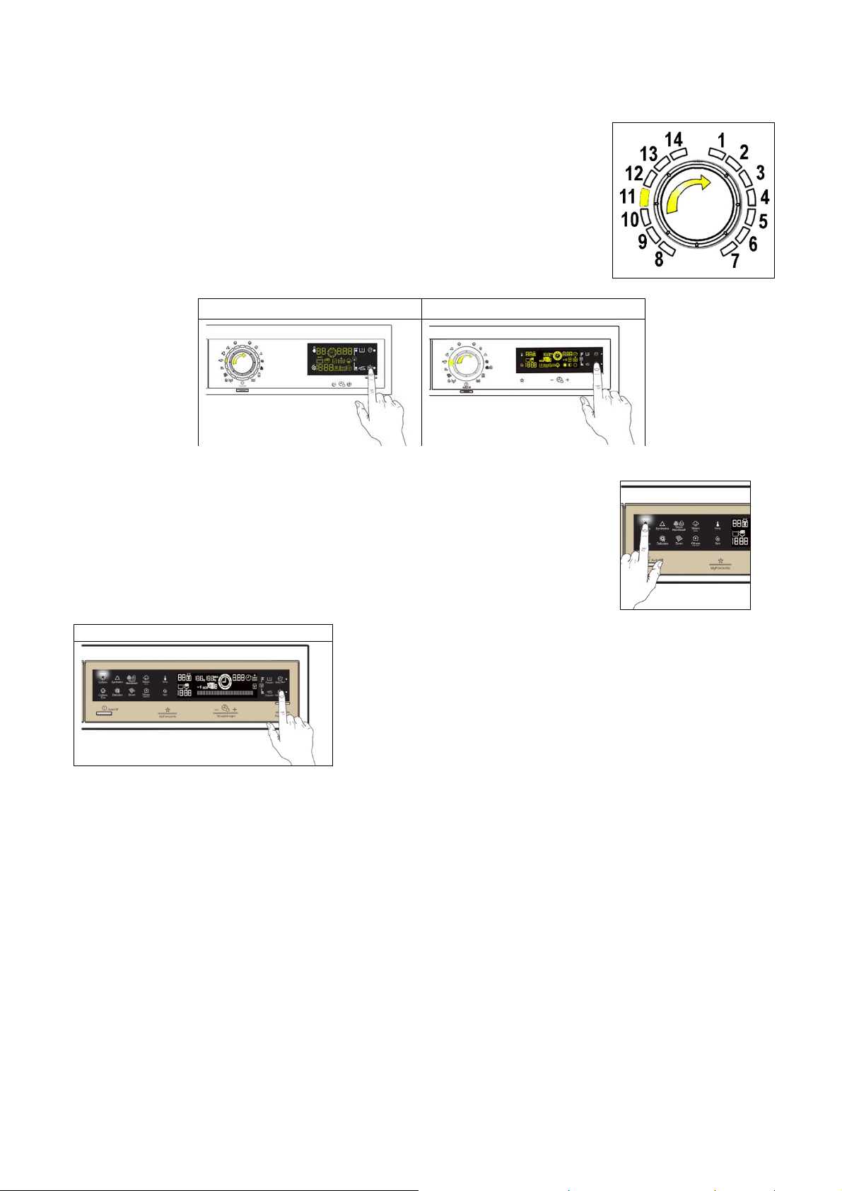
4.1 Accessing diagnostics
The operations listed below must be carried out within 7 seconds.
TC 3 TC 2 TC 1
Do not start the procedure with your fingers over the combination sensors
1. Switch on the appliance using the ON/OFF button. The first LED lights up.
2. Simultaneously press the START/PAUSE button and the nearest option sensor (as shown in the
diagram).
3. Hold your fingers over the sensors until the LEDs and symbols begin to flash in sequence (approximately
3 seconds).
In the first position, the operation of the sensors, the LEDs and the groups of symbols shown on the LCD
display is checked;
For the TC3 and TC2 styling:
When the programme selector is turned in a clockwise direction, the operation of the various components is
diagnosed and the alarms are read (see diagnostic test on the next page).
For the TC1 styling:
Since there is no selector with which to perform the diagnostics of the various components and the alarm
reading, the two sensors shown in the figure below are used (the top one is used to move forward
progressively and the bottom one to move backwards in the same way). Concurrently, the function performed
is described in the text line (see diagnostic test on page 11).
Next Previous
During this phase, if any combination of sensors (except the one for diagnosis) is pressed, all the option
combinations stored will be deleted (Extra rinse, Buzzer disable, etc.).
4.2 Quitting the diagnostics system
→ To exit the diagnostic cycle, switch the appliance off, then back on and then off again.
Guide to diagnostics of electronic controls EWM10931
2012 TS/DT-mdm FCPD-dp 9/79 599 75 27-46 Rev.00
4.3 Phases of the diagnostics test
4.3.1 TC3-TC2 styling
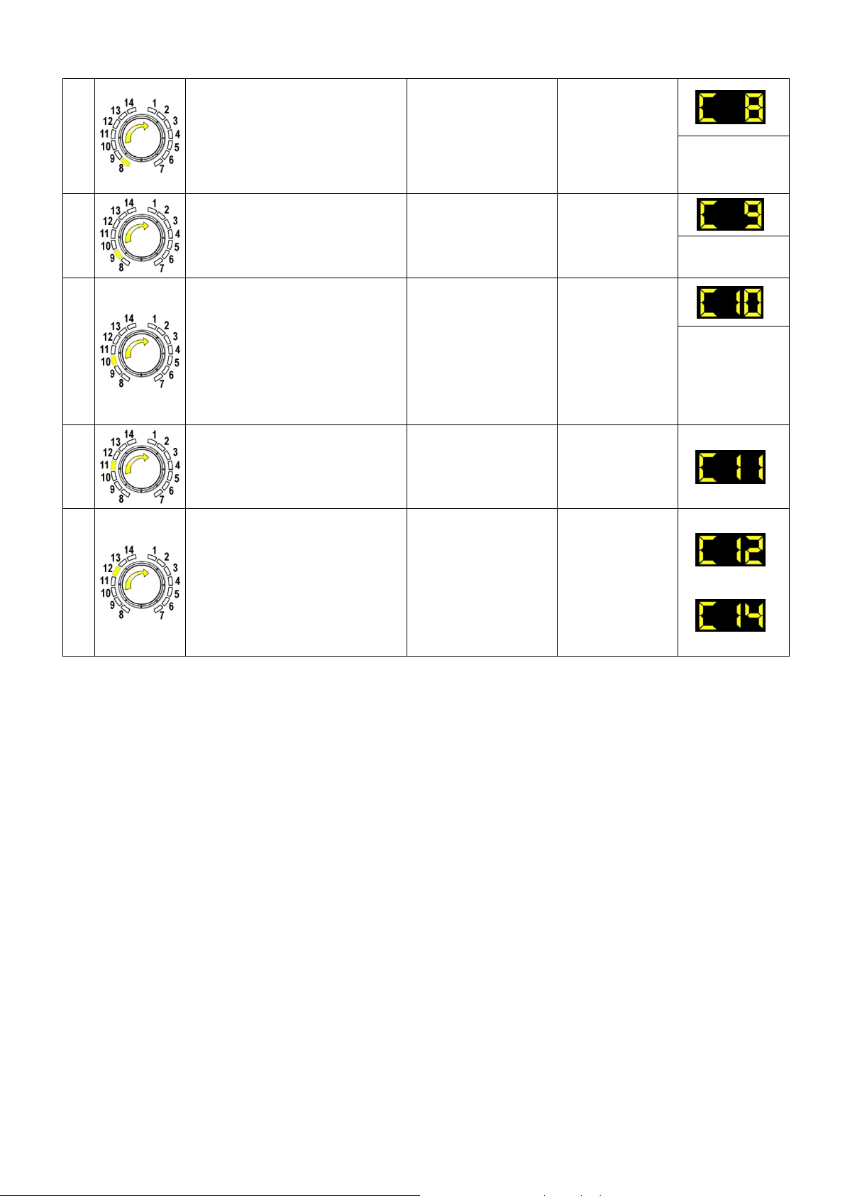
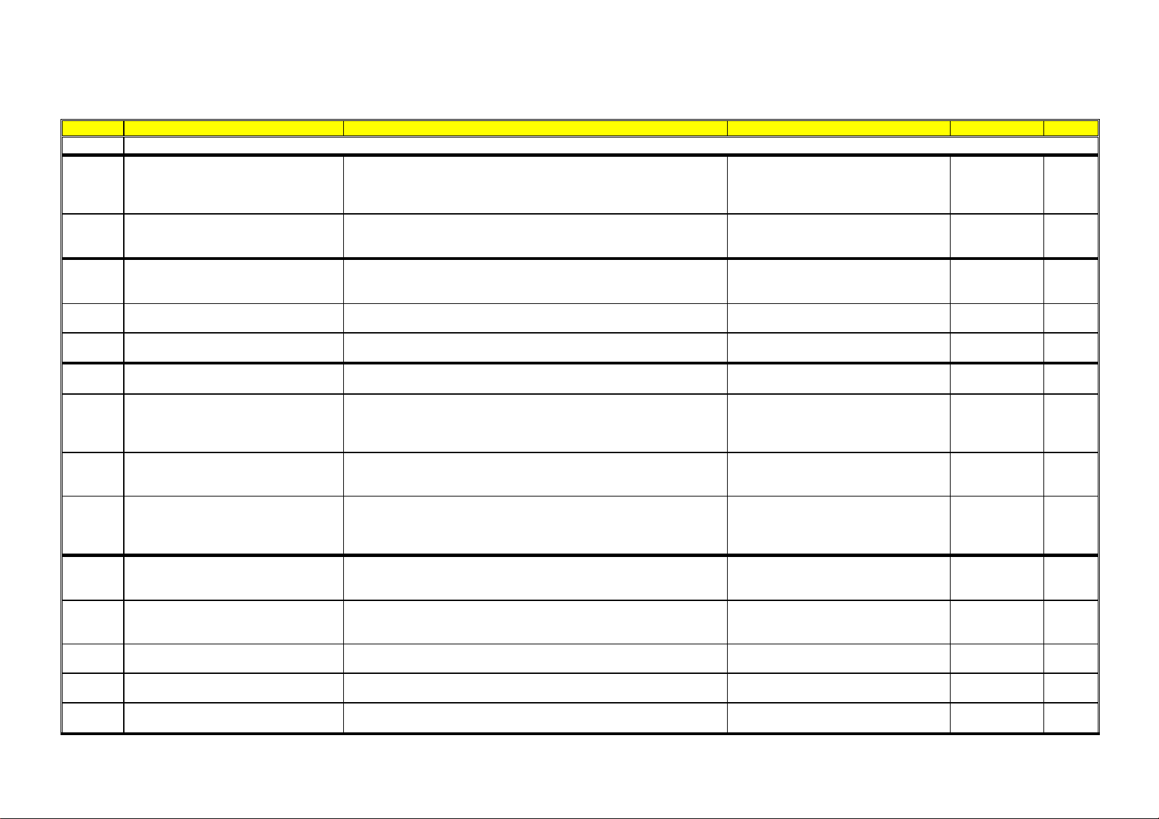
Irrespective of the type of PCB and the configuration of the programme selector, after entering the diagnostic
mode, turn the programme selector dial clockwise to perform the diagnostic cycle for the operation of the
various components and to read any alarms.
Concurrently, a selector control code is shown on the LCD display, which indicates for two seconds the
description in the last column of the table below.
(all alarms are enabled in the diagnostic cycle).
Selector
position
Components activated Working conditions Function tested LCD display
1
- The LEDs, groups of symbols
in the LCD screen and the
backlight of the display are
turned on in sequence
- Touch a sensor to turn on the
group of icons in the LCD
screen or the corresponding
LED and the buzzer sounds at
the same time
Always active
User interface
functioning
2
- Door safety interlock
- Wash solenoid valve
Door closed
Water level below
anti-flooding level
Maximum time 5 mins.
Water fill to wash
compartment
Water level in
the tub (mm)
3
- Door safety interlock
- Pre-wash solenoid valve
Door closed
Water level below
anti-flooding level
Maximum time 5 mins.
Water fill to pre-
wash
compartment
Water level in
the tub (mm)
4
- Door safety interlock
- Solenoid valve pre-wash
and wash
Door closed
Water level below
anti-flooding level
Maximum time 5 mins.
Water fill to
conditioner
compartment
Water level in
the tub (mm)
5
- Door safety interlock
- Third solenoid valve
Door closed
Water level below
anti-flooding level
Maximum time 5 mins.
Water fill to third
solenoid valve
compartment
Water level in
the tub is
displayed (mm)
6
- Door safety interlock
- Fourth solenoid valve
(hot water where featured)
Door closed
Water level below
anti-flooding level
Maximum time 5 mins.
Water fill to
fourth solenoid
valve
compartment
Water level in
the tub is
displayed (mm)
7
- Door safety interlock
- Wash solenoid valve, if the
water in the tub is not enough
to cover the heating element
- Heating element
- Weight sensor (if there is one,
an extra litre of water is
loaded)
- Circulation pump
Door closed
Water level above the
heating element
Maximum time
10 mins up to 90°C (*)
Reheating
Circulation
Temperature in
°C measured
using the NTC
probe
Guide to diagnostics of electronic controls EWM10931
2012 TS/DT-mdm FCPD-dp 10/79 599 75 27-46 Rev.00
8
- Door safety interlock
- Wash solenoid valve, if the
water in the tub is not enough
to cover the heating element
- Motor (55 rpm clockwise,
55 rpm anti-clockwise,
250 rpm pulse)
Door closed
Water level above the
heating element
Check for leaks
from the tub
Drum speed in
rpm/10
9
- Door safety interlock
- Drain pump
- Motor up to 650 rpm then at
maximum spin speed (**)
Door closed
Water level lower
than anti-boiling level
for spinning
Drain, calibration
of analogue
pressure switch
and spin
Drum speed in
rpm/10
10
- Door safety interlock
- Drain pump
- Power fan
- Condensation solenoid valve
- Drying heating element
Door closed
Water level below
anti-boiling level
Maximum time
10 minutes
Drying
Displays the air
temperature
alternating
detection by
the two NTC
probes
11
- Reading/Deleting the last alarm ----- ----
12
÷
14
- The LEDs, groups of symbols
in the LCD screen and the
backlight of the display are
turned on in sequence
- Touch a sensor to turn on the
group of icons in the LCD
screen or the corresponding
LED and the buzzer sounds at
the same time
Always active
User interface
functioning
(*) In most cases, this time is sufficient to check the heating. H owever, the time can be increased by repeating the phase without draining
the water: pass f or a moment to a different phase of the diagnostic cycle and then back to the heating control phase (if the temperatur e is
higher than 80°C, heating does not take place).
(**) The check at the maximum speed occurs without control of the A.G.S. and no garments must be inside the appliance.
Guide to diagnostics of electronic controls EWM10931
2012 TS/DT-mdm FCPD-dp 11/79 599 75 27-46 Rev.00
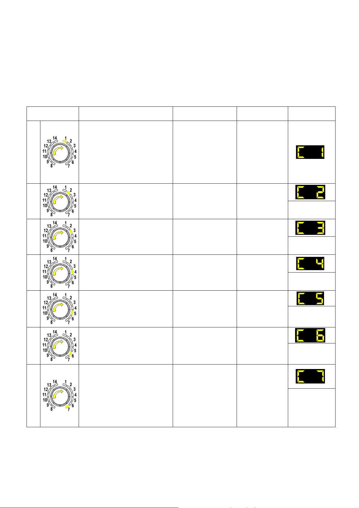
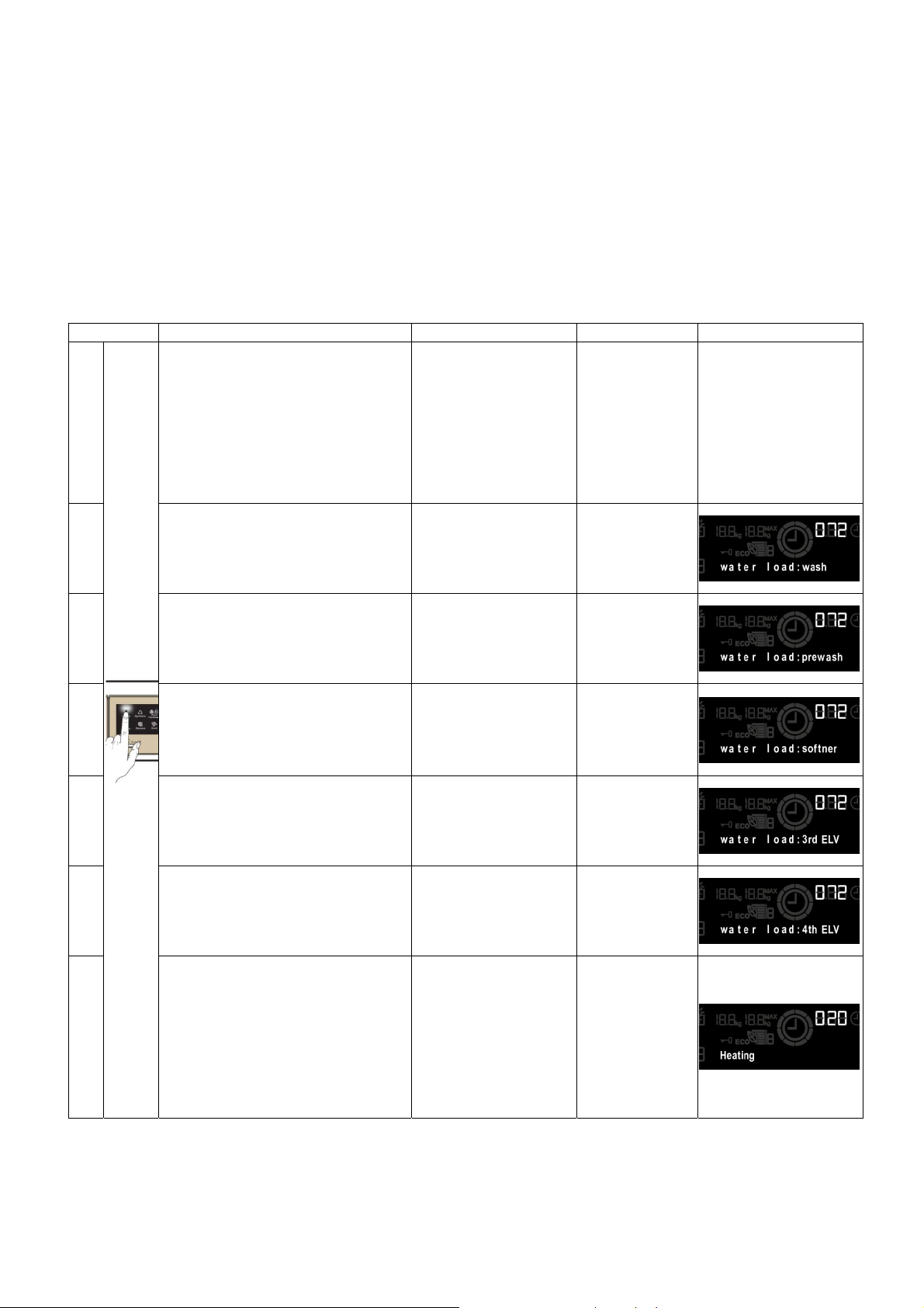
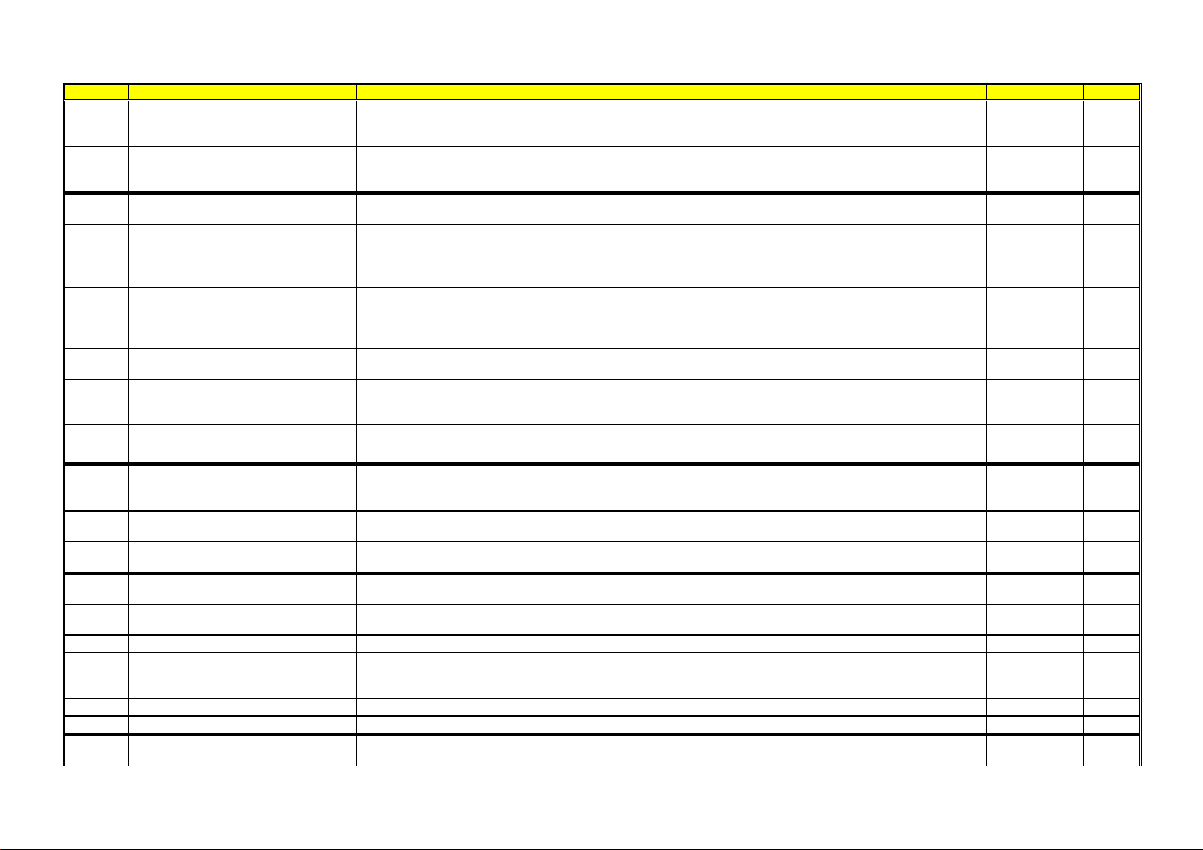
4.3.2 TC1 styling
Irrespective of the type of circuit board and the configuration of the programmes, after entering the diagnostic
mode, touch the sensor to the left of the display (as shown in the figure) to perform the diagnostic cycle for the
operation of the various components and to read any alarms.
The LCD display shows the function checked in the middle (see third column) and at the top right, using the
three digits:
¾ the water level in the tub, during the solenoid valve activation phases.
¾ the temperature in degrees °C, during the heating phases.
¾ the drum revolutions in rpm/10, during the phases when the motor is powered.
(all alarms are enabled in the diagnostic cycle)
Location Components activated Working conditions Function tested LCD display
1
- The LEDs are turned on in
sequence, as are the symbol
groups of the LCD display and
its backlight
- Touch a sensor to turn on the
group of icons in the LCD
screen or the corresponding
LED and the buzzer sounds at
the same time
Always active
User interface
functioning
2
- Door safety interlock
- Wash solenoid valve
Door closed
Water level below
anti-flooding level
Maximum time 5 mins.
Water fill to
wash
compartment
3
- Door safety interlock
- Pre-wash solenoid valve
Door closed
Water level below
anti-flooding level
Maximum time 5 mins.
Water fill to
pre-wash
compartment
4
- Door safety interlock
- Solenoid valve
pre-wash and wash
Door closed
Water level below
anti-flooding level
Maximum time 5 mins.
Water fill to
conditioner
compartment
5
- Door safety interlock
- Third solenoid valve
Door closed
Water level below
anti-flooding level
Maximum time 5 mins.
Water fill to
third solenoid
valve
compartment
6
- Door safety interlock
- Fourth solenoid valve (hot water
where featured)
Door closed
Water level below
anti-flooding level
Maximum time 5 mins.
Water fill to
fourth solenoid
valve
compartment
7
- Door safety interlock
- Wash solenoid valve, if the
water in the tub is not enough to
cover the heating element
- Heating element
- Weight sensor (if there is one,
an extra litre of water is loaded)
- Circulation pump
Door closed
Water level above the
heating element
Maximum time
10 mins up to 90°C (*)
Reheating
Circulation
Guide to diagnostics of electronic controls EWM10931
2012 TS/DT-mdm FCPD-dp 12/79 599 75 27-46 Rev.00
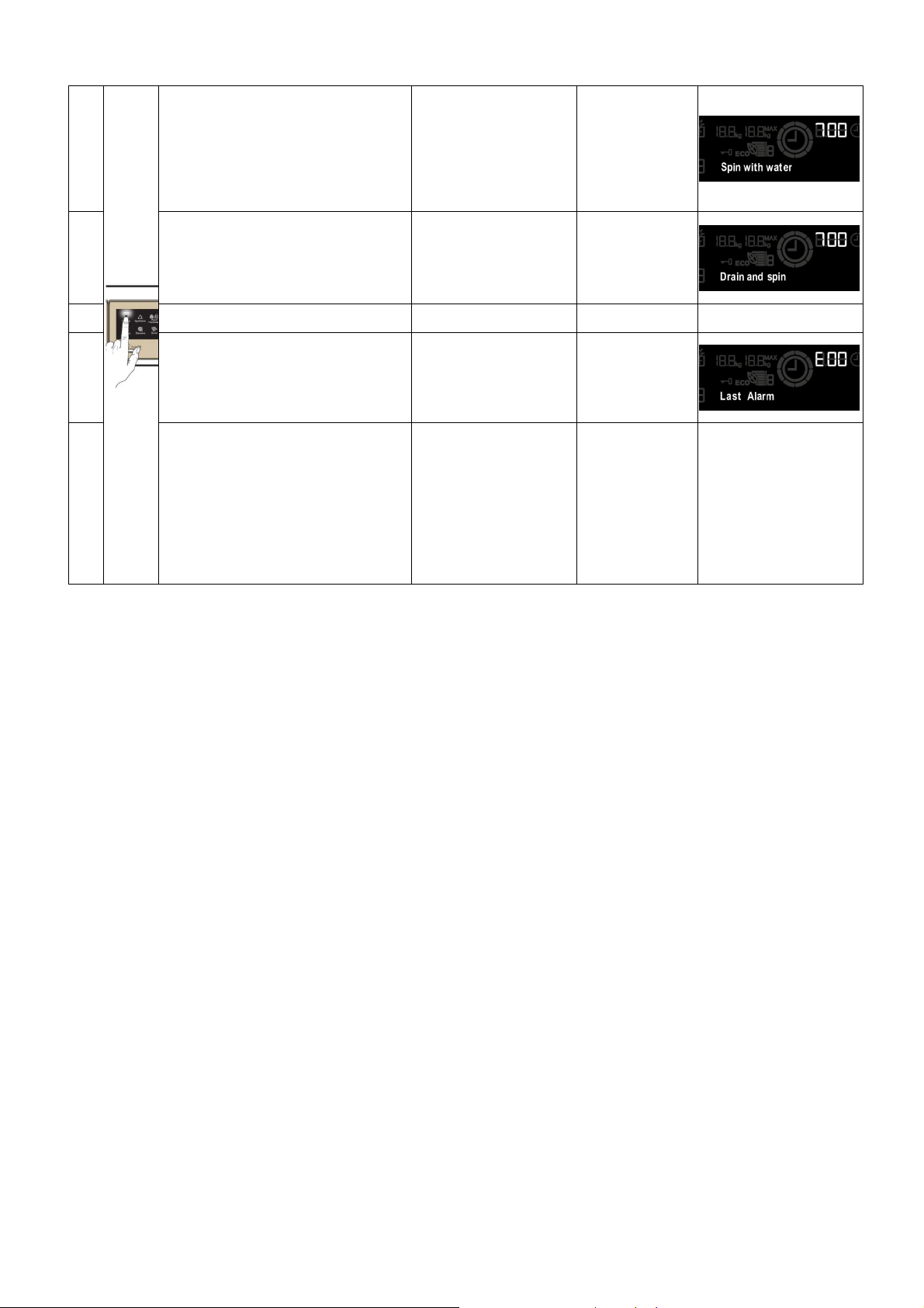
8
- Door safety interlock
- Wash solenoid valve, if the
water in the tub is not enough to
cover the heating element
- Motor (55 rpm clockwise,
55 rpm anti-clockwise,
250 rpm pulse)
Door closed
Water level above
the heating element
Check for leaks
from the tub
9
- Door safety interlock
- Drain pump
- Motor up to 650 rpm then at
maximum spin speed (**)
Door closed
Water level lower
than anti-boiling level
for spinning
Drain,
calibration of
analogue
pressure switch
and spin
10
----- ----- ----- -----
11
- Reading/Deleting the last alarm ----- ----
12
÷
14
- The LEDs, groups of symbols in
the LCD screen and the
backlight of the display are
turned on in sequence
- Touch a sensor to turn on the
group of icons in the LCD screen
or the corresponding LED and
the buzzer sounds at the same
time
Always active
User interface
functioning
(*) In most cases, this time is sufficient to check the heating. H owever, the time can be increased by repeating the phase without draining
the water: pass f or a moment to a different phase of the diagnostic cycle and then back to the heating control phase (if the temperatur e is
higher than 80°C, heating does not take place).
(**) The check at the maximum speed occurs without control of the A.G.S. and no garments must be inside the appliance.
Guide to diagnostics of electronic controls EWM10931
2012 TS/DT-mdm FCPD-dp 13/79 599 75 27-46 Rev.00
5 ALARMS
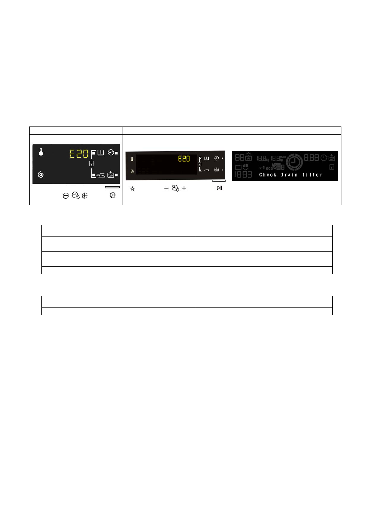
5.1 Displaying the alarms to the user
When a problem occurs in the appliance, the LCD display shows a “WARNING”:
− in stylings TC3 and TC2 with a code (in the three digits, where the time until the end of the cycle is
represented).
− in styling TC1, a message is shown (in the text line).
This information ceases to be displayed when the problem is repaired/solved. The buzzer then emits a
sound (three short “beeps”every 20” for 5 minutes). This does not occur for alarm EH0.
TC 3 TC 2
TC 1
The alarms displayed to the user are listed below and can also be eliminated by the user:
TC3 / TC2 TC1
E10 - Water fill difficulty (tap closed) Check the tap
E20 - Drain difficulty (
f
ilter dirty) Check the drain filter
E40 - Door open Check the door
EF0 - Excessive detergent Excessive detergen
t
EH0 -
V
oltage or frequency outside normal values Unstable frequency or voltage
While the alarm listed below:
TC3 / TC2 TC1
EF0 - Water leakage (Aqua Control System) Caution: water
The intervent ion of a service engineer is required.
The other alarms are displayed by a code.
The alarms are enabled during the execution of the washing programme. With the exception of alarms
associated w ith the configuration and the power supply voltage/frequency, whic h ar e also displayed dur ing
the programme selec tion phase.
The door can normally be opened (except where specified) when an alarm condition has occurred, on
condition that:
• The level of the water in the tub is below a certain level.
• The water temperature is lower than 55°C.
• The motor has stopped.
Certain alarm conditions require a drain phase to be performed before the door can be opened for safety
reasons:
• Cooling water fill if the temperature is greater than 65°C.
• Drain until the analogue pressure switch is on empty, during a max. 3 minute interval.
Guide to diagnostics of electronic controls EWM10931
2012 TS/DT-mdm FCPD-dp 14/79 599 75 27-46 Rev.00
5.2 Reading the alarms
The last three alarms stored in the FLASH memory of the PCB can be
displayed:
5.2.1 TC3-TC2 styling
• Enter the diagnostic mode (para. 3.1).
• Irrespective of the type of PCB and configuration, turn the programme
selector knob clockwise to the eleventh position the last alarm is displayed.
• To display previous alarms, touch the sensor closest to the START/PAUSE
sensor in sequence (as shown in the figure).
• To return to the last alarm, touch the START/PAUSE sensor.
5.2.2 TC1 styling
• Enter the diagnostic mode (para. 3.1).
• Irrespective of the type of circuit board and configuration, using the sensor
shown in the figure, go to the eleventh position and the last alarm is
displayed.
• To display previous alarms, touch the sensor closest to the START/PAUSE
sensor in sequence (as shown in the figure below).
• To return to the last alarm, touch the START/PAUSE sensor.
TC 1
5.3 Rapid reading of alarms
It is possible to display the last alarm even if the selector is not in the eleventh diagnostics position or if the
appliance is in normal operating mode (for example when performing a wash programme):
→ Touch the START/PAUSE sensor and the nearest option sensor simultaneously (as if you were
entering DIAGNOSTIC mode) and hold for at least 2 seconds: the LCD display shows the last alarm.
The alarm will continue to be displayed until a sensor is touched.
The alarm reading system is as described in para. 4.2.
While the alarm is being displayed, the appliance continues to perform the cycle or, if in the programme
selection phase, it stores the previously selected options.
TC 3 TC 2
Guide to diagnostics of electronic controls EWM10931
2012 TS/DT-mdm FCPD-dp 15/79 599 75 27-46 Rev.00
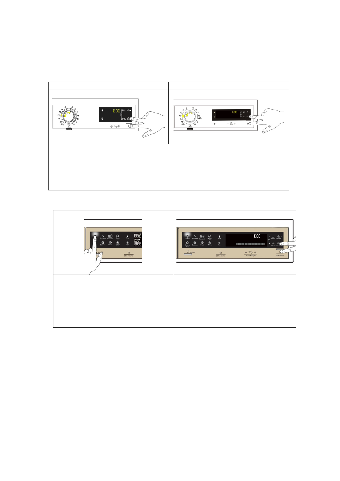
5.4 Deleting the last alarm
It is good practice to cancel the alarms stored:
• after reading the alarm codes, to check whether the alarm re-occurs during the diagnostic cycle
• after repairing the appliance, to check whether it re-occurs during testing
TC 3 TC 2
1. Enter the diagnostic mode (para. 3.1).
2. Turn the selector clockwise until the eleventh LED lights up.
3. Simultaneously press the START/PAUSE sensor and the nearest option sensor (as
shown in the diagram).
4. Keep your fingers over the sensors until the LCD display shows “E00” (at least
5 seconds).
TC 1
1. Enter the diagnostic mode (para. 3.1).
2. Irrespective of the type of circuit board and configuration, touch the sensor (shown in
fig. a) to go to the eleventh position and the alarm is displayed.
3. Simultaneously press the START/PAUSE sensor and the nearest option sensor
(as shown in fig. b).
4. Keep your fingers over the sensors until the LCD display shows “E00” (at least
5 seconds).
N.B. With this operation all the alarms stored are deleted.
Fig. a Fig. b
Guide to diagnostics of electronic controls EWM10931
2012 TS/DT-mdm FCPD-dp 16/79 599 75 27-46 Rev.00
5.5 ALARM SUMMARY TABLE
Alarm Description Possible faul
t
Machine status/a
c
tion Rese
t
Page
E00
E11 Water fill difficulty during washing
Tap closed or water pressure too low; drain pipe improperly
positioned; water fill solenoid valve faulty; leaks from water circuit on
pressure switch; pressure switch faulty; wiring faulty; main PCB
faulty.
Cycle is paused with door locked START/RESET 20
E13 Water leaks
Drain pipe improperly positioned; water pressure too low
Water fill solenoid valve faulty; water circuit on pressure switch is
leaking/clogged; pressure switch faulty.
Cycle is paused with door locked START/RESET 22
E21
Drain difficulty during washing
Drain pipe kinked/clogged/improperly positioned; drain filter
clogged/dirty; wiring faulty; pressure switch faulty; drain pump rotor
blocked; drain pump faulty; main PCB faulty.
Cycle is paused
(after 2 attempts)
START
ON/OFF
RESET
24
E23
Faulty triac for drain pump Wiring faulty; drain pump faulty; main PCB fault.
Safety drain cycle - Cycle stops with
door open
RESET 26
E24
Drain pump triac “sensing” circuit
faulty
Main circuit board faulty.
Safety drain cycle - Cycle stops with
door unlocked
RESET 28
E31
Malfunction in electronic pressure
switch circuit
Wiring; Electronic pressure switch; Main PCB. Cycle stops with door locked RESET 28
E32
Calibration error of the electronic
pressure switch
Drain pipe kinked/clogged/improperly positioned; solenoid valve
faulty; drain filter clogged/dirty; drain pump faulty; leaks from pressure
switch hydraulic circuit; pressure switch faulty;
Wiring; main PCB.
Cycle is paused START/RESET 29
E35
Overflow
Water fill solenoid valve faulty; leaks from water circuit on pressure
switch; wiring faulty; pressure switch faulty; main PCB faulty.
Cycle interrupted. Safety drain cycle.
Drain pump continues to operate (5 min.
on, then 5 min. off. etc.)
RESET 30
E38
Internal pressure chamber is
clogged (water level does not
change for at least 30 sec. of drum
rotation)
Motor belt broken; water circuit on pressure switch clogged. Heating phase is skipped RESET 31
E41
Door open
Check whether the door is closed properly;
Wiring faulty; door safety interlock faulty;
Main circuit board faulty.
Cycle is paused START/RESET 32
E42 Problems with door lock
Wiring faulty; door safety interlock faulty;
Electrical current leak between heating element and ground; main
PCB faulty.
Cycle is paused START/RESET 34
E43
Faulty triac supplying power to door
delay system
Wiring faulty; door safety interlock faulty;
Main circuit board faulty.
(Safety drain cycle)
Cycle blocked
RESET 36
E44
Faulty sensing by door delay system Main circuit board faulty.
(Safety drain cycle)
Cycle blocked
RESET 37
E45
Faulty sensing by door delay system
triac
Main circuit board faulty.
(Safety drain cycle)
Cycle blocked
RESET 37

Guide to diagnostics of electronic controls EWM10931
2012 TS/DT-mdm FCPD-dp 17/79 599 75 27-46 Rev.00
Alarm Description Possible faul
t
Machine status/a
c
tion Rese
t
Page
E52
No signal from motor tachometric
generator
Wiring faulty; Motor faulty;
Inverter board faulty.
Cycle stops with door locked
(after 5 attempts)
ON/OFF
RESET
38/40
E57
Inverter is drawing too much current
(
>15 A)
Wiring faulty on inverter for motor; inverter PCB faulty; motor faulty.
Cycle stops with door locked
(after 5 attempts)
ON/OFF
RESET
42
E58
Inverter is drawing too much current
(
>4.5 A)
Motor malfunction (overload); Wiring faulty on inverter faulty; motor
faulty; inverter PCB faulty.
Cycle stops with door locked
(after 5 attempts)
ON/OFF
RESET
44
E59
No signal from tachometric
generator for 3 seconds
Wiring faulty on inverter for motor; inverter PCB faulty; motor faulty.
Cycle stops with door locked
(after 5 attempts)
ON/OFF
RESET
46
E5A
Overheating on heat dissipator for
Inverter
Overheating caused by continuous operation or ambient conditions
(let appliance cool down); Inverter PCB faulty. NTC open (on the
Inverter PCB).
Cycle stops with door locked
(after 5 attempts)
ON/OFF
RESET
48
E5C Input voltage is too high
Input voltage is too high (m easure the grid voltage); Inverter PCB
faulty.
Cycle stops with door locked
(after 5 attempts)
ON/OFF
RESET
49
E5d
Data transfer error between Inverter
and main PCB
Line interference; wiring faulty; faulty main PCB or inverter PCB. ----------------
ON/OFF
RESET
50
E5E
Communication error between
Inverter and main PCB
Faulty wiring between main PCB and inverter PCB; Inverter PCB
faulty; Main PCB faulty.
Cycle blocked
(after 5 attempts)
ON/OFF
RESET
51
E5F
Inverter PCB fails to start the motor Wiring faulty; Inverter PCB faulty; Main PCB faulty.
Cycle stops with door open
(after 5 attempts)
ON/OFF
RESET
51
E5H
Input voltage is lower than 175 V Wiring faulty; Inverter PCB faulty.
Cycle stops with door locked
(after 5 attempts)
ON/OFF
RESET
52
E62
Overheating during
w
ashing
(temperature higher than 88°C for
more than 5 min.)
Wiring faulty; NTC probe for wash cycle faulty; Heating element
faulty; Main PCB faulty.
Safety drain cycle
Cycle stops with door open
RESET 53
E66
Heating element power relay faulty
(inconsistency between sensing and
K2 relay status)
Main PCB faulty.
Safety water fill
Cycle stops with door closed.
ON/OFF
RESET
54
E68 Current leak to the ground Current leakage between heating element and ground. The heating phase is skipped START/RESET 55
E69 Heating element interrupted
Wiring faulty; Heating element for washing interrupted (thermal fuse
open); Main PCB faulty.
----------------
START
ON/OFF
RESET
56
E6
A
Heating relay sensing faulty Main circuit board faulty. Cycle stops with door locked RESET 57
E6H
Heating element power relay faulty
(inconsistency between sensing and
K1 relay status)
Wiring faulty; Earth-leakage between heating element and earth;
Main PCB faulty.
Safety water fill
Cycle stops with door closed.
ON/OFF
RESET
57
E71
NTC probe fo
r
wash cycle faulty
(short-circuited or open)
Wiring faulty; NTC probe for wash cycle faulty;.
Main circuit board faulty.
The heating phase is skipped START/RESET 58
E74
NTC probe for wash cycle
improperly positioned
Wiring faulty; NTC probe for wash cycle improperly positioned; NTC
probe faulty; Main PCB faulty.
The heating phase is skipped RESET 59
E83
Error in reading selector Main PCB faulty (Incorrect configuration data). Cycle cancelled START/RESET 60
Guide to diagnostics of electronic controls EWM10931
2012 TS/DT-mdm FCPD-dp 18/79 599 75 27-46 Rev.00
Alarm Description Possible faul
t
Machine status/a
c
tion Rese
t
Page
E86 Selector configuration error Display board. ----------------
START
ON/OFF
RESET
60
E87
Display board microprocessor faulty If this continues, replace the display board. No action to be taken
START
ON/OFF
RESET
60
E91
Communication error between main
PCB and display
Wiring faulty; Control/display PCB faulty;
Main circuit board faulty; Inverter PCB faulty; Weight sensor faulty.
---------------- RESET 61
E92
Communication inconsistency
between main PCB and display
(incompatible versions)
Incorrect control/display PCB;
Incorrect PCB (does not correspond to the model).
Cycle blocked ON/OFF 62
E93
Appliance configuration error Main PCB faulty (incorrect configuration data). Cycle blocked ON/OFF 62
E94
Incorrect configuration of washing
cycle
Main PCB faulty (incorrect configuration data). Cycle blocked ON/OFF 62
E97
Inconsistency between programme
selector and cycle configuration
Main PCB faulty (incorrect configuration data). Cycle blocked RESET 62
E98
Communication error between main
PCB - Inverter
Incompatibility between main PCB and Inverter. Cycle blocked ON/OFF 62
E9C
Display board configuration error Display board faulty. ----------------
START
ON/OFF
RESET
63
E9E
Display board sensor/touch key
faulty
Display board faulty. ---------------- ON/OFF 63
EC1
Electronically controlled valve
blocked with operating flowmeter
Wiring faulty; Solenoid valve faulty/blocked, Main PCB faulty.
Cycle stops with door locked
Drain pump continues to operate (5 min.
on, then 5 min. off. etc.)
RESET 64
EC2
Data transfer error between Weight
sensor and main PCB.
Wiring faulty; Weight sensor faulty, PCB faulty. No action to be taken START/RESET 65
EC3
Problems with weight sensor (no
signal or outside the limits)
Wiring faulty; Weight sensor faulty; Main PCB faulty. ---------------- START/RESET 66
EF1
Drain filter clogged
(drain phase too long)
Drain filter clogged/dirty;
Drain hose blocked/kinked/too high.
Warning displayed at the end of cycle START/RESET 67
EF2
Overdosing of detergent (too much
foam during drain phases)
Excessive detergent dosing; Drain hose kinked/blocked;
Drain filter clogged/dirty.
Warning displayed after 5 attempts or
by the specific LED
RESET 67
EF3
Aqua control system intervention Water leaks onto base frame; Aqua control system faulty. Appliance drains ON/OFF RESET 67
EF4
Water fill pressure too low, no signal
from flowmeter and electronically
controlled valve is open
Tap closed, water fill pressure too low. ---------------- RESET 67
EF
5
Unbalanced load Final spin phases skipped. ---------------- START/RESET 67
EF6 Reset If it continues, replace the main board. No action to be taken ---------------- 68
EH1
Supply frequency of appliance
outside the limits
Problem with the power supply network (incorrect/disturbed); Main
PCB faulty.
Wait for nominal frequency conditions ON/OFF 68
Guide to diagnostics of electronic controls EWM10931
2012 TS/DT-mdm FCPD-dp 19/79 599 75 27-46 Rev.00
Alarm Description Possible faul
t
Machine status/a
c
tion Rese
t
Page
EH2
Supply voltage too high
Problem with the power supply network (incorrect/disturbed); Main
PCB faulty.
Wait for nominal voltage conditions ON/OFF 68
EH3 Supply voltage too low
Problem with the power supply network (incorrect/disturbed); Main
PCB faulty.
Wait for nominal voltage conditions ON/OFF 69
EH4
0 Watt relay malfunction Main circuit board faulty. ----------------
ON/OFF
RESET
69
EHE
Inconsistency between FCV relay
(in the main board) and safety
“sensing” circuit
Faulty wiring; Main circuit board faulty.
Safety drain cycle
Cycle stops with door open
RESET 69
EHF
Safety sensing circuit faulty (wrong
input voltage to microprocessor)
Main circuit board faulty.
Safety drain cycle
Cycle stops with door open
RESET 69

Guide to diagnostics of electronic controls EWM10931
2012 TS/DT-mdm FCPD-dp 20/79 599 75 27-46 Rev.00
5.6 Notes on the behaviour of certain alarms
Configuration alarm E93: when this alarm rings (when turned on) the machine blocks and the alarm code appears on the display provided the relevant
configuration part is intact.
It will not be possible to access diagnostics mode and the only available option is to turn the appliance off.
Configuration alarm E94: and the code can be viewed from the display.
The diagnostics mode cannot be accessed and the “quick alarm viewing” mode cannot be used.
Alarms EH1-EH2-EH3: in the event of problems with the supply voltage, the appliance remains in alarm status until the mains frequency or voltage returns to
acceptable values or the appliance is switched off (ON/OFF button). Only the “H” alarm family is displayed if the problem occurs while the appliance is
working normally, the code is shown simultaneously on the display.
The diagnostics mode cannot be accessed and the “quick alarm viewing” mode cannot be used: the alarm can only be read in full when the situation has
normalised.
Alarms E51- E52: all the alarms are displayed during diagnostic testing: normally, when shifting from one control phase to another, the appliance quits the
alarm mode and executes the selected phase. This is not the case for alarms E51 (motor power supply TRIAC short-circuiting) and E52 (no signal from motor
tachometric generator): the only possibility to exit the alarm situation is to rotate the programme switch to the “0” position (reset) for the TC2 and TC3 stylings,
while for the TC1 styling press the ON/OFF button.
Guide to diagnostics of electronic controls EWM10931
2012 TS/DT-mdm FCPD-dp 21/79 599 75 27-46 Rev.00
6 CANNOT ACCESS THE DIAGNOSTICS PROGRAMME
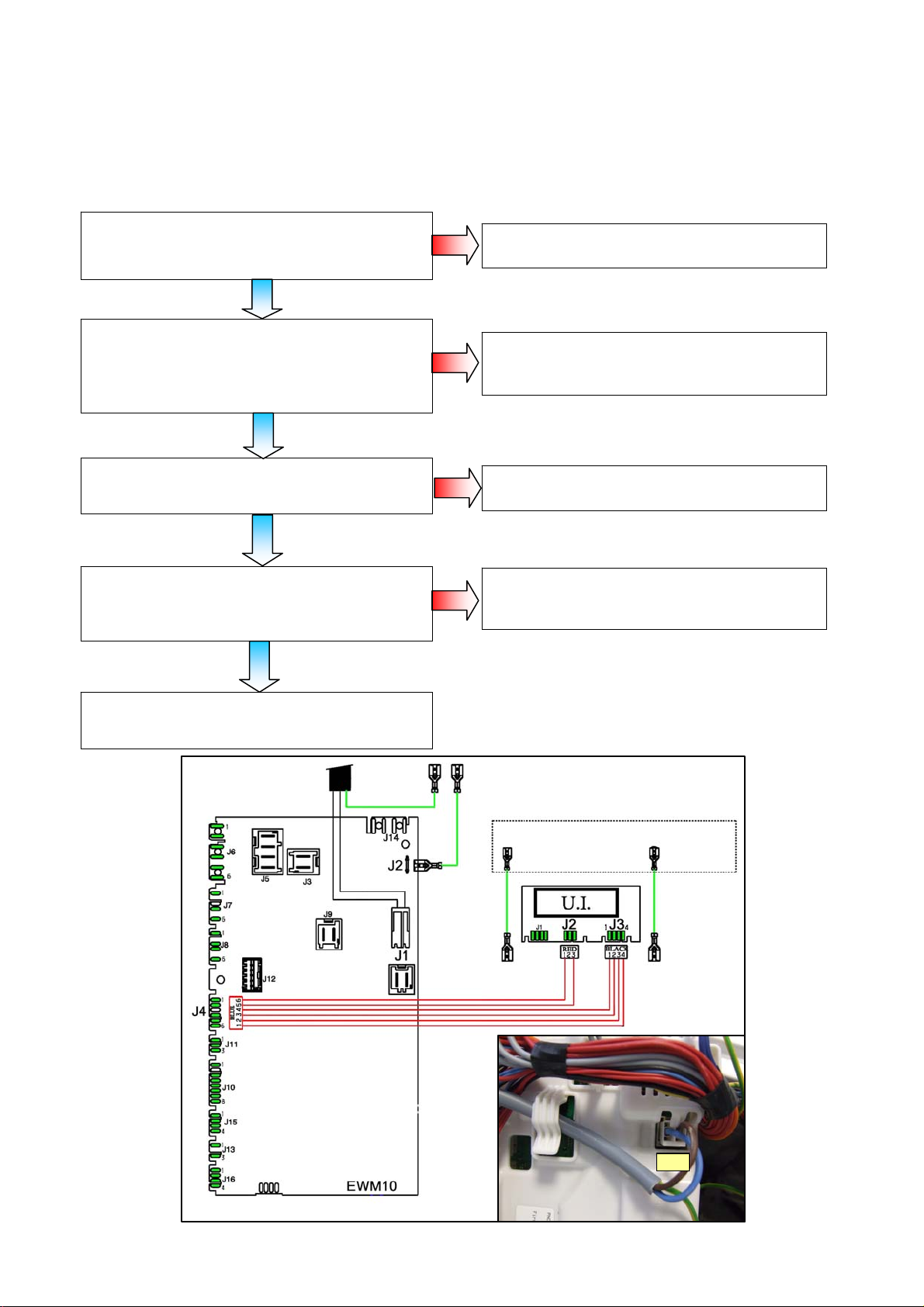
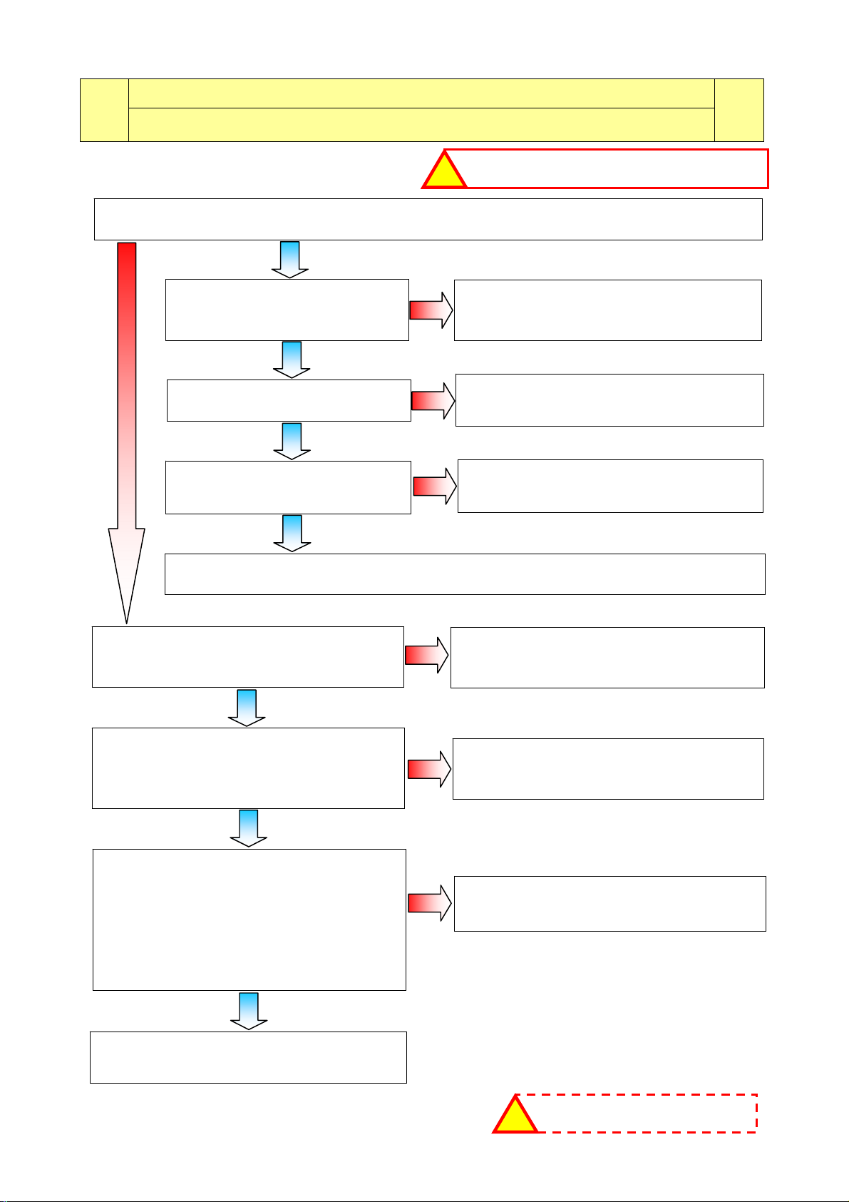
6.1 None of the LEDs on the circuit board light up
NO
NO
NO
NO
MAIN CIRCUIT
BOARD
DISPLAY BOARD
GENERAL EARTHING
J1
Are the power supply cable and the connection
on the main board (connector J1) working
properly?
Replace/repair the power supply cable, check
the connection.
Is the communication wiring between the main
board (connector J4) and the display board
(connectors J2 and J3) working properly? (insert
and remove)
Replace/repair wiring.
Does the ON/OFF button function mechanically?
Replace/repair the button or replace the display
board.
Change the main circuit board.
Is the appliance working correctly?
Replace display board.
Run the diagnostics programme.
Y
E
S
Y
E
S
Y
E
S
Y
E
S
Guide to diagnostics of electronic controls EWM10931
2012 TS/DT-mdm FCPD-dp 22/79 599 75 27-46 Rev.00
Run the diagnostic cycle and fill all the trays with water (phases 2,3,4,5,6).
Are all the trays filling with water?
7 TROUBLESHOOTING BASED ON ALARM CODES
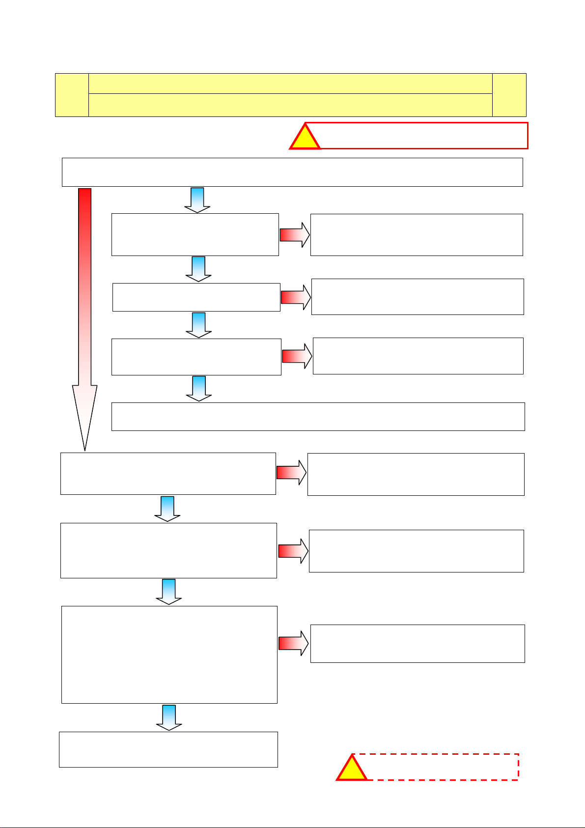
E11
E11: Water fill difficulty during washing
E11
Maximum water fill time for every level of the pressure switch
(the time is reset every time the level is achieved)
Checks to perform:
Repair the drain circuit and repeat the
diagnostic cycle to check for any further alarms.
Repair the water circuit of the pressure switch
and repeat the diagnostic cycle to check for
any further alarms.
Replace the main circuit board and repeat the diagnostic cycle to check for any further alarms.
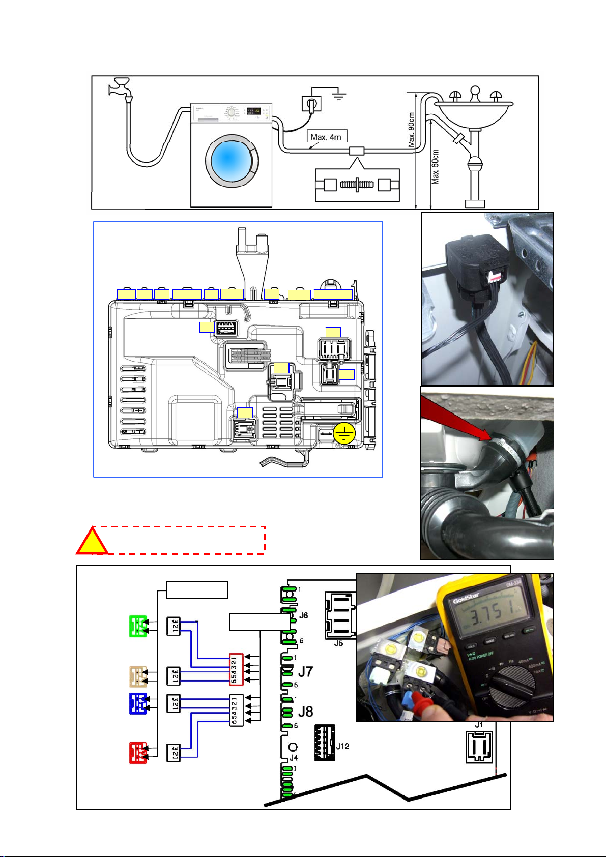
Is the drain tube positioned
correctly and not causing the siphon
effect? (fig. 1)
Is the pressure switch's water circuit
efficient (leaking/clogged)?
(fig. 2)
Check whether the tap is open, if the water
pressure is too low and make sure the tubes are
connected and not kinked.
Is one or are all the solenoid valves not
working?
Replace the solenoid valve and repeat the
diagnostic cycle to check for any further alarms.
Is the resistance measurement of the solenoid
valve approximately 3.5÷4.5 KΩ? (Measure it
directly on the solenoid valve without wiring)
-(see fig. 3)-
Replace/repair the wiring and repeat the
diagnostic cycle to check for any further alarms.
Reconnect the connector and measure
approximately 3.5÷4.5 KΩ on the solenoid valve
wiring connector on the circuit board side
(fig. 4): Between J7-1 and J7-3 wash
Between J7-4 and J7-6 pre-wash
Between J8-1 and J8-3 third solenoid valve
Between J8-4 and J8-6 hot water
Is the solenoid valve wiring ok?
Replace the main circuit board and repeat the
diagnostic cycle to check for any further alarms.
Repair the water circuit and repeat the
diagnostic cycle to check for any further alarms.
Is the washing machine's water
circuit efficient (leaking)?
Y
E
S
NO
Y
E
S
Y
E
S
Y
E
S
Y
E
S
NO
NO
NO
N
O
NO
NO
Y
E
S
Y
E
S
Check that all the connectors ar e correctly inserted
!
If there are burns on the circuit board,
see page 77
!
Guide to diagnostics of electronic controls EWM10931
2012 TS/DT-mdm FCPD-dp 23/79 599 75 27-46 Rev.00
E11
MAIN CIRCUIT
BOARD
3.5÷4.5 K
3.5÷4.5 K
WASHING
PRE-
WASHING
HOT
WATER
3rd
SOLENOID
V
ALVE
Fig. 3
J16 J13
J15
J10
J11 J4 J8
J7 J6
J12
J5
J3
J9
J1
Fig. 4
If there are burns on the circuit board,
see page 77
!
Fig. 1
Fig.
2
Fig. 2
Guide to diagnostics of electronic controls EWM10931
2012 TS/DT-mdm FCPD-dp 24/79 599 75 27-46 Rev.00
Run the diagnostic cycle and fill all the trays with water (phases 2,3,4,5,6).
Are all the trays filling with water?
E13
E13: Water leaks
E13
Maximum overall water fill time exceeded (sum of all water fills between one drain phase
and the next to avoid exceeding the maximum volume).
Checks to perform:
Repair the drain circuit and repeat the
diagnostic cycle to check for any further alarms.
Repair the water circuit of the pressure switch
and repeat the diagnostic cycle to check for
any further alarms.
Replace the main circuit board and repeat the diagnostic cycle to check for any further alarms.
Is the drain tube positioned
correctly and not causing the siphon
effect? (fig. 1)
Is the pressure switch's water circuit
efficient (leaking/clogged)?
(fig. 2)
Check whether the tap is open, if the water
pressure is too low and make sure the tubes are
connected and not kinked.
Is one or are all the solenoid valves not
working?
Replace the solenoid valve and repeat the
diagnostic cycle to check for any further alarms.
Is the resistance measurement of the solenoid
valve approximately 3.5÷4.5 KΩ? (Measure it
directly on the solenoid valve without wiring)
-(see fig. 3)-
Replace/repair the wiring and repeat the
diagnostic cycle to check for any further alarms.
Reconnect the connector and measure
approximately 3.5÷4.5 KΩ on the solenoid valve
wiring connector on the circuit board side
(fig. 4): Between J7-1 and J7-3 wash
Between J7-4 and J7-6 pre-wash
Between J8-1 and J8-3 third solenoid valve
Between J8-4 and J8-6 hot water
Is the solenoid valve wiring ok?
Replace the main circuit board and repeat the
diagnostic cycle to check for any further alarms.
Repair the water circuit and repeat the
diagnostic cycle to check for any further alarms.
Is the washing machine's water
circuit efficient (leaking)?
Y
E
S
NO
Y
E
S
Y
E
S
Y
E
S
Y
E
S
NO
NO
NO
N
O
NO
NO
Y
E
S
Y
E
S
Check that all the connectors ar e correctly inserted
!
If there are burns on the circuit board,
see page 77
!
 Loading...