


SERVICE MANUAL
WASHING
|
|
|
WM-WD |
|
© ELECTROLUX ITALIA S.p.A. |
Publication no. |
Front loader |
|
|
Spares Operations Italy |
|
|
||
Corso Lino Zanussi, 30 |
|
|
Platform |
|
I - 33080 PORCIA /PN (ITALY) |
599 72 40-80 |
|
|
|
|
|
|
||
Fax +39 0434 394096 |
EN |
EWM1000 |
|
|
|
|
|
EWM1000plus |
|
|
|
|
EWM2000evo |
|
|
|
|
EWM3000new |
|
Edition: 12-2009 |
|
|
ENV06 |
|
|
|
|
11xx21xx |
|
|
|
|
25xx/35xx |
|
|
|
|
|
|
QUICK GUIDE AND APPLIANCES LIST |
2/176 |
599 72 40-80 |
Content
1 |
EWM1000 ............................................................................................................................................ |
|
5 |
|
|
1.1 |
Access to the diagnostic cycle .................................................................................................... |
|
5 |
|
1.2 |
Rapid reading of alarms.............................................................................................................. |
|
5 |
|
1.3 |
Cancelling the last alarm............................................................................................................. |
|
5 |
|
1.4 |
Phases of the diagnostics test..................................................................................................... |
|
6 |
|
1.5 |
Reading the alarms..................................................................................................................... |
|
7 |
|
1.5.1 |
Displaying the alarm.............................................................................................................. |
|
7 |
|
1.5.2 |
Examples of alarm display..................................................................................................... |
|
7 |
|
1.5.3 |
Status of alarms during the diagnostics cycle......................................................................... |
7 |
|
|
1.6 |
Table of alarms codes EWM1000 ............................................................................................... |
|
8 |
|
1.6.1 |
Notes concerning certain alarm codes ................................................................................... |
9 |
|
|
1.7 |
Elementary diagram.................................................................................................................. |
|
10 |
|
1.7.1 |
With instantaneous door locking device ............................................................................... |
10 |
|
|
1.8 |
With PTC door locking device ................................................................................................... |
|
11 |
|
1.8.1 |
Key to circuit diagram.......................................................................................................... |
|
12 |
|
1.9 |
Connectors on circuit board EWM1000 ..................................................................................... |
|
13 |
|
1.10 |
Burning on the circuit board EWM1000 ..................................................................................... |
|
14 |
|
1.10.1 |
EWM1000 ........................................................................................................................... |
|
14 |
|
1.10.2 |
Components side (common)................................................................................................ |
|
14 |
|
1.10.3 |
Pushbutton – led side (horizontal buttons) ........................................................................... |
15 |
|
|
1.10.4 |
Pushbutton – led side (vertical buttons) ............................................................................... |
15 |
|
2 |
EWM1000plus 2000evo 3000new..................................................................................................... |
|
16 |
|
|
2.1 |
Control panel ............................................................................................................................ |
|
16 |
|
2.2 |
Sigma/Alpha/Ellipse//Multipanel Built-In/Sigma-ZK/Jewel with or without selector...................... |
17 |
|
|
2.2.1 |
Access to diagnostics system.............................................................................................. |
|
17 |
|
2.2.2 |
Rapid reading of alarm codes.............................................................................................. |
|
17 |
|
2.2.3 |
Cancelling the last alarm ..................................................................................................... |
|
17 |
|
2.3 |
AEG NexXxt Version with selector and incorporated ON/OFF switch......................................... |
18 |
|
|
2.3.1 |
Access to diagnostics system.............................................................................................. |
|
18 |
|
2.3.2 |
Rapid reading of alarm codes.............................................................................................. |
|
18 |
|
2.3.3 |
Cancelling the last alarm ..................................................................................................... |
|
18 |
|
2.4 |
AEG New Version with right selector and incorporated ON/OFF switch ..................................... |
19 |
|
|
2.4.1 |
Access to diagnostics system.............................................................................................. |
|
19 |
|
2.4.2 |
Rapid reading of alarm codes.............................................................................................. |
|
19 |
|
2.4.3 |
Cancelling the last alarm ..................................................................................................... |
|
19 |
|
2.5 |
DELTA Version without selector and button ON/OFF switch...................................................... |
20 |
|
|
2.5.1 |
Access to diagnostics system.............................................................................................. |
|
20 |
|
2.5.2 |
Rapid reading of alarm codes.............................................................................................. |
|
20 |
|
2.5.3 |
Cancelling the last alarm ..................................................................................................... |
|
20 |
|
2.6 |
CLUB DISPLAY Version with selector and incorporated ON/OFF switch ................................... |
21 |
|
|
2.6.1 |
Access to diagnostics system.............................................................................................. |
|
21 |
|
2.6.2 |
Rapid reading of alarm codes.............................................................................................. |
|
21 |
|
2.6.3 |
Cancelling the last alarm ..................................................................................................... |
|
21 |
|
2.7 |
LCD Version without selector and button ON/OFF switch.......................................................... |
22 |
|
|
2.7.1 |
Access to diagnostics system.............................................................................................. |
|
22 |
|
2.7.2 |
Rapid reading of alarm codes.............................................................................................. |
|
22 |
|
2.7.3 |
Cancelling the last alarm ..................................................................................................... |
|
22 |
|
2.8 |
LCD Version with selector and button ON/OFF switch............................................................... |
23 |
|
|
2.8.1 |
Access to diagnostics system.............................................................................................. |
|
23 |
|
2.8.2 |
Rapid reading of alarm codes.............................................................................................. |
|
23 |
|
2.8.3 |
Cancelling the last alarm ..................................................................................................... |
|
23 |
|
2.9 |
Phases of the diagnostics test................................................................................................... |
|
24 |
|
2.10 |
Reading the alarm codes .......................................................................................................... |
|
26 |
|
2.10.1 |
Displaying the alarm............................................................................................................ |
|
26 |
|
2.10.2 |
Examples of alarm displays................................................................................................. |
|
26 |
|
2.11 |
Table of alarms codes EWM 1000plus |
EWM2000EVO EWM3000NEW................................. |
27 |
|
2.12 |
Basic circuit diagram EWM1000PLUS....................................................................................... |
|
31 |
|
2.12.1 |
Diagram (without aqua control)............................................................................................ |
|
31 |
|
2.12.2 |
Key to circuit diagram.......................................................................................................... |
|
32 |
|
2.12.3 |
Diagram (with aqua control)................................................................................................. |
|
33 |
|
2.12.4 |
Key to circuit diagram.......................................................................................................... |
|
34 |
|
2.13 |
Basic circuit diagram with sensor EWM2000EVO...................................................................... |
35 |
|
QUICK GUIDE AND APPLIANCES LIST |
3/176 |
599 72 40-80 |
||
|
2.13.1 |
Key for circuit diagram......................................................................................................... |
36 |
|
2.14 |
Basic circuit diagram with sensor EWM3000NEW ..................................................................... |
37 |
|
2.14.1 |
Key for circuit diagram......................................................................................................... |
38 |
|
2.15 |
Connectors on circuit board EWM1000plus............................................................................... |
39 |
|
2.16 |
Burning on the circuit board EWM1000plus............................................................................... |
40 |
3 |
ENV 06............................................................................................................................................... |
41 |
|
|
3.1 |
Access to the diagnostic cycle .................................................................................................. |
41 |
|
3.1.1 |
All version ........................................................................................................................... |
41 |
|
3.1.2 |
INPUT version..................................................................................................................... |
41 |
|
3.1.3 |
Rapid reading of alarm codes.............................................................................................. |
41 |
|
3.2 |
Cancelling the last alarm........................................................................................................... |
42 |
|
3.3 |
Phases of the diagnostic cycle .................................................................................................. |
43 |
|
3.4 |
Alarm displaying ....................................................................................................................... |
44 |
|
3.4.1 |
AEG Version: ...................................................................................................................... |
44 |
|
3.4.2 |
Other versions:.................................................................................................................... |
44 |
|
3.4.3 |
Examples of alarm display................................................................................................... |
44 |
|
3.4.4 |
Operation of alarms during diagnostics................................................................................ |
44 |
|
3.5 |
Table of alarms codes ENV06................................................................................................... |
44 |
|
3.5.1 |
Notes concerning certain alarm codes ................................................................................. |
44 |
|
3.6 |
Basic circuit diagram EWM1100................................................................................................ |
44 |
|
3.6.1 |
Key to circuit diagram EWM1100......................................................................................... |
44 |
|
3.7 |
Connectors on circuit board EWM1100 ..................................................................................... |
44 |
|
3.8 |
Burning on the circuit board EWM1100 ..................................................................................... |
44 |
|
3.9 |
Basic circuit diagram WM EWM2100 ........................................................................................ |
44 |
|
3.9.1 |
Key to circuit diagram WM EWM2100.................................................................................. |
44 |
|
3.10 |
Basic circuit diagram WM with aqua control EWM2100 ............................................................. |
44 |
|
3.10.1 Key to circuit diagram WM with Aqua Control EWM2100 ..................................................... |
44 |
|
|
3.11 |
Basic circuit diagram WD EWM2100......................................................................................... |
44 |
|
3.11.1 Key to circuit diagram WD EWM2100.................................................................................. |
44 |
|
|
3.12 |
Basic circuit diagram WD with aqua control EWM2100.............................................................. |
44 |
|
3.12.1 Key to circuit diagram WD with aqua control EWM2100....................................................... |
44 |
|
|
3.13 |
Connectors on circuit board WM/WD EWM2100 ....................................................................... |
44 |
|
3.14 |
Burning on the circuit board EWM2100 WM/WD ....................................................................... |
44 |
|
3.15 |
Basic circuit diagram EWM25xx without aqua control................................................................ |
44 |
|
3.15.1 Key to circuit diagram EWM25xx with Aqua Control............................................................. |
44 |
|
|
3.16 |
Basic circuit diagram EWM25xx without aqua control................................................................ |
44 |
|
3.16.1 Key to circuit diagram EWM25xx without Aqua Control........................................................ |
44 |
|
|
3.17 |
Basic circuit diagram EWM25xx WD without aqua control ......................................................... |
44 |
|
3.17.1 Key to circuit diagram EWM25xx WD with Aqua Control ...................................................... |
44 |
|
|
3.18 |
Basic circuit diagram EWM25xx WD without aqua control ......................................................... |
44 |
|
3.18.1 Key to circuit diagram EWM25xx WD without aqua control .................................................. |
44 |
|
|
3.19 |
Basic circuit diagram EWM35xx with aqua control..................................................................... |
44 |
|
3.19.1 Key to circuit diagram EWM35xx with Aqua Control............................................................. |
44 |
|
|
3.20 |
Basic circuit diagram EWM35xx without aqua control................................................................ |
44 |
|
3.20.1 Key to circuit diagram EWM35xx without Aqua Control........................................................ |
44 |
|
|
3.21 |
Connectors on circuit board WM/WD EWM25xx/35xx ............................................................... |
44 |
|
3.22 |
Burning on the circuit boards EWM25xx/35xx WM/WD.............................................................. |
44 |
|
3.23 |
Burning on the circuit board WD................................................................................................ |
44 |
4 |
Appliances list .................................................................................................................................... |
44 |
|
QUICK GUIDE AND APPLIANCES LIST |
4/176 |
599 72 40-80 |
EWM1000
1 EWM1000
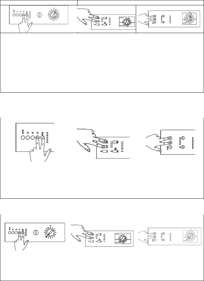
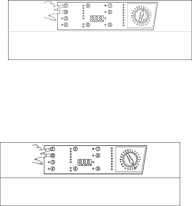
1.1Access to the diagnostic cycle
version with horizontal pushbuttons |
version with vertical pushbuttons |
1.Switch off the appliance.
2.Press and hold down the START/PAUSE button and any one of the OPTION buttons simultaneously. horizontal version, while for vertical version pushbuttons are 2 and 3.
3.Holding down both buttons, switch the appliance on by turning the programme selector one position clockwise.
4.Continue to hold down the START/PAUSE button and the OPTION button horizontal version, while for vertical version pushbuttons are 2 and 3, until the LEDs begin to flash (at least 2 seconds).
5.To exit the diagnostics system switch the appliance off, on and then off again.
IMPORTANT: The position of the START/PAUSE button varies according to the model, and is therefore not always the same.
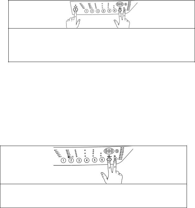
1.2Rapid reading of alarms
The last alarm can be displayed even if the programme selector is not in the tenth position (diagnostics) or if the appliance is in normal operating mode (e.g. while the washing programme is in operation):
version with horizontal pushbuttons |
version with vertical pushbuttons |
|
|
|
|
1.Press START/PAUSE and any one of the option buttons simultaneously for horizontal version, while for vertical version pushbuttons are 2 and 3, for at least two seconds: the LEDs first switch off, and then display the flashing sequence corresponding to the alarm condition.
2.The alarm sequence continues as long as the two buttons are held down.
3.While the alarms are displayed, the current cycle being performed continues or, if the appliance is in the programme selection phase, the options previously selected remain in memory.
1.3Cancelling the last alarm
version with horizontal pushbuttons |
version with vertical pushbuttons |
|
|
|
|
1.Access alarm reading mode (tenth selector position)
2.Press and hold down START/PAUSE and any one of the option keys simultaneously for horizontal version, while for vertical version pushbuttons are 2 and 3.
3.Hold the START/PAUSE and OPTION button down until the LEDs begin to flash (about 5 seconds)
EWM1000
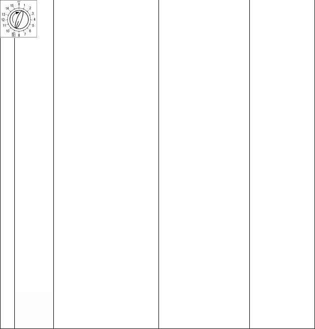
1.4Phases of the diagnostics test
After accessing the diagnostics cycle, and irrespective of the type of control board fitted to the appliance (i.e. vertical or horizontal buttons) and the configuration of the selector, turn the programme selector clockwise to perform the diagnostics cycle for the various components and to read the alarms.
All the alarms are enabled during the diagnostics cycle.
|
Position of |
Components activated |
Conditions of operation |
Function tested |
|||
|
selector |
||||||
|
|
|
|
||||
|
|
|
- |
All the LEDs light in sequence |
|
|
|
1 |
|
|
- |
When a button is pressed, the |
Always enabled |
Operation of the |
|
|
|
|
corresponding LED lights (and |
user interface |
|||
|
|
|
|
the buzzer may sound) |
|
|
|
|
|
|
|
|
|
|
|
|
|
|
|
Door safety interlock |
Door locked |
Water ducted |
|
2 |
|
|
- |
Water level lower than anti- |
|||
|
|
through washing |
|||||
|
|
- |
Washing solenoid valve |
overflow level |
|||
|
|
|
compartment |
||||
|
|
|
|
|
Maximum time 5 minutes |
||
|
|
|
|
|
|
||
|
|
|
|
|
|
|
|
|
|
|
|
Door safety interlock |
Door locked |
Water ducted |
|
3 |
|
|
- |
Water level lower than anti- |
through pre-wash |
||
|
|
- |
Pre-wash solenoid valve |
overflow level |
(bleach) |
||
|
|
|
|
|
Maximum time 5 minutes |
compartment |
|
|
|
|
|
|
|
|
|
|
|
|
- |
Door safety interlock |
Door locked |
Water ducted |
|
4 |
|
|
Water level lower than anti- |
||||
|
|
- |
Washing and pre-wash solenoid |
through conditioner |
|||
|
|
|
|
valves |
overflow level |
compartment |
|
|
|
|
|
Maximum time 5 minutes |
|||
|
|
|
|
|
|
||
|
|
|
|
|
|
|
|
|
|
|
- |
Door safety interlock |
Door locked |
|
|
6 |
|
|
- |
Wash solenoid (if the water in |
Water level > 1st level |
Heating |
|
|
|
|
the tub is below 1st level) |
Maximum time 10 minutes or |
|||
|
|
|
- |
Heating element |
up to 90°C (*) |
|
|
|
|
|
|
|
|
|
|
|
|
|
- |
Door safety interlock |
|
|
|
|
|
|
|
|
|||
|
|
|
- |
Wash solenoid (if the water in |
|
|
|
7 |
|
|
|
the tub is below 1st level) |
Door locked |
Check for leaks |
|
|
|
- |
Motor (55 rpm clockwise, 55 |
Water level > 1st level |
from the tub |
||
|
|
|
|
rpm anti-clockwise, impulse at |
|
|
|
|
|
|
|
250 rpm) |
|
|
|
|
|
|
|
|
|
||
|
|
|
- |
Door safety interlock |
Door locked |
Drain and spin, |
|
|
|
|
check for |
||||
8 |
|
|
- |
Drain pump |
|||
|
|
Water level lower then anti- |
congruence in |
||||
|
|
- |
Motor up to 650 rpm then at |
||||
|
|
|
boiling level for spinning |
closure of pressure |
|||
|
|
|
|
maximum spin speed |
|||
|
|
|
|
|
switch levels |
||
|
|
|
|
|
|
||
|
|
|
Only for top-loaders with drum |
Door locked |
|
||
|
|
|
|
positioning system: |
|
||
9 |
|
|
|
Water level lower then anti- |
Test for positioning |
||
- |
Door safety interlock |
||||||
boiling level |
of drum |
||||||
|
- |
Motor (25 rpm) |
|||||
-Drain pump Maximum time 2 minutes
(*)In most cases, this time is sufficient to check the heating function. However, the time can be increased by repeating the heating phase without draining the water: pass for a moment to a different phase of the diagnostics cycle and then back to the heating check phase (if the temperature is higher than 80°C, heating does not take place).
QUICK GUIDE AND APPLIANCES LIST |
6/176 |
599 72 40-80 |

EWM1000
1.5Reading the alarms
Proceed as follows to read the last alarm condition stored in the EEPROM on the control board:
•Access diagnostics mode.
•Irrespective of the type of control board and configuration, turn the programme selector clockwise to the tenth position.
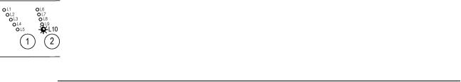
1.5.1Displaying the alarm
The alarm is displayed by a repeated flashing sequence of the two LEDs (0.4 seconds ON, 0.4 seconds OFF, with a pause of 2.5 seconds between each sequence). The buzzer (if featured) sounds a series of “beeps” in synchronization with the flashing of the LEDs.
•END OF CYCLE indicator → indicates the first digit of the alarm code (family)
•START/PAUSE → indicates the second digit of the alarm code (number
within the family).
These two LEDs are present on all models (though configured in different positions) and flash simultaneously.
Notes:
•The first letter of the alarm code “E” (Error) is not displayed since it is the same for all alarm codes.
•The alarm code families are expressed in hexadecimal form. In other words:
→A is represented by 10 flashes
→B is represented by 11 flashes
→...
→F is represented by 15 flashes
•Configuration errors are displayed by the flashing of all the LEDs (user interface not configured).
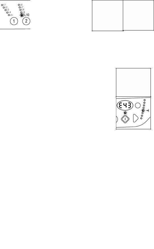
1.5.2Examples of alarm display
Example: Alarm E43 (problems with the door safety interlock triac) will be displayed as follows:
•four flashes of the END OF CYCLE LED indicate the first digit E43;
•three flashes of the START/PAUSE LED indicate the second digit E43;
END OF CYCLE LED |
|
|
|
|
START/PAUSE LED |
|
|
|
||||||
ON/OFF |
Time |
Value |
ON/OFF |
Time |
Value |
|||||||||
(seconds) |
(seconds) |
|||||||||||||
|
|
|
|
|
|
|
|
|
|
|
|
|||
|
|
|
0.4 |
1 |
|
|
|
|
0.4 |
1 |
|
|||
|
|
|
|
|
|
|
|
|
|
|||||
|
|
|
0.4 |
|
|
|
|
0.4 |
|
|||||
|
|
|
|
|
|
|
|
|
|
|
|
|||
|
|
|
|
|
|
|
|
|
|
|
|
|
|
|
|
|
|
0.4 |
2 |
|
|
|
|
0.4 |
2 |
|
|||
|
|
|
|
|
|
|
|
|
|
|||||
|
|
|
0.4 |
|
|
|
|
0.4 |
|
|||||
|
|
|
|
|
|
|
|
|
|
|
|
|||
|
|
|
|
|
|
|
|
|
|
|
|
|
|
|
|
|
|
0.4 |
3 |
|
|
|
|
0.4 |
3 |
|
|||
|
|
|
|
|
|
|
|
|
|
|||||
|
|
|
0.4 |
|
|
|
|
0.4 |
|
|||||
|
|
|
|
|
|
|
|
|
|
|
|
|||
|
|
|
|
|
|
|
|
|
|
|
|
|
|
|
|
|
|
0.4 |
4 |
|
|
|
|
|
|
|
|
||
|
|
|
|
|
|
|
|
3,3 |
Pause |
|||||
|
|
|
0.4 |
|
|
|
|
|||||||
|
|
|
|
|
|
|
|
|
||||||
|
|
|
|
|
|
|
|
|
|
|
|
|||
|
|
|
2.5 |
Pause |
|
|
|
|
|
|
|
|||
|
|
|
|
|
|
|
|
|
|
|
|
|
|
|
1.5.3Status of alarms during the diagnostics cycle
All the alarms are enabled during the components diagnostics test.
QUICK GUIDE AND APPLIANCES LIST |
7/176 |
599 72 40-80 |
EWM1000
1.6Table of alarms codes EWM1000
Alarm |
Description |
Possible fault |
Action/Machine status |
Reset |
|
E00 |
|
No alarm |
|
|
|
|
|
Tap closed or water pressure insufficient; Drain hose |
|
|
|
E11 |
Difficulty in filling during wash phase |
incorrectly positioned; Water fill solenoid faulty; Leaks from |
Cycle paused, door closed |
Start |
|
|
|
pressure switch hydraulic circuit; Pressure switch faulty; |
|
|
|
|
|
Wiring faulty; Circuit board faulty. |
|
|
|
|
|
Drain hose incorrectly positioned; Water pressure |
|
|
|
E13 |
Water leakage |
insufficient; Water fill solenoid faulty; Leaks or blockage in |
Cycle paused, door closed |
Start |
|
pressure switch hydraulic circuit; Pressure switch faulty; |
|||||
|
|
|
|
||
|
|
Circuit board faulty. |
|
|
|
|
|
Drain hose kinked/blocked/incorrectly positioned; Drain filter |
|
|
|
E21 |
Difficulties in draining |
clogged or dirty; Drain pump faulty; Pressure switch faulty; |
Cycle paused |
Start |
|
|
|
Wiring faulty; Circuit board faulty; Current leakage from |
|
|
|
|
|
heating element to ground. |
|
|
|
E23 |
Drain pump triac faulty |
Drain pump faulty; Wiring faulty; Circuit board faulty. |
Safety drain - Cycle stopped, door open |
Selector on “0” |
|
E24 |
Problems with «sensing» of drain pump triac |
Circuit board faulty. |
Safety drain – Cycle stopped, door released |
Selector on “0” |
|
E33 |
Incongruence between contact closure of anti- |
Pressure switch faulty; Current leakage from heating |
|
|
|
element to ground; Heating element; Wiring faulty; Circuit |
Safety drain - Cycle stopped, door open |
Selector on “0” |
|||
|
boiling and 1st level of pressure switch |
board faulty. |
|
|
|
|
|
|
|
||
E35 |
|
Water fill solenoid faulty; Leaks from pressure switch |
Cycle blocked, door closed. Safety drain. |
|
|
Water overflow |
hydraulic circuit; Pressure switch faulty; Wiring faulty; Circuit |
Drain pump (sequence 5 min. ON - 5 min. |
Selector on “0” |
||
|
|
board faulty. |
OFF) |
|
|
E36 |
«sensing» circuit of anti-boiling pressure switch |
Circuit board faulty. |
Cycle blocked, door closed |
Selector on “0” |
|
|
faulty |
|
|
|
|
E37 |
«sensing» circuit of 1st level faulty |
Circuit board faulty. |
Cycle blocked, door closed |
Selector on “0” |
|
E39 |
HV «sensing» circuit of anti-flooding pressure |
Circuit board faulty. |
Cycle blocked, door closed |
Selector on “0” |
|
|
switch faulty |
|
|
|
|
E41 |
Door open |
Door safety interlock faulty; Wiring faulty; |
Cycle paused |
Start |
|
Circuit board faulty. |
|||||
|
|
|
|
||
E42 |
Problems with aperture of door |
Door safety interlock faulty; Wiring faulty; |
Cycle paused |
Start or Selector |
|
Circuit board faulty |
on “0” |
||||
|
|
|
|||
E43 |
Power triac on door interlock faulty |
Door safety interlock faulty; Wiring faulty; |
Safety drain, door released |
Selector on “0” |
|
Circuit board faulty. |
|||||
|
|
|
|
||
E44 |
Door interlock «sensing» faulty |
Circuit board faulty. |
Safety drain, door released |
Selector on “0” |
|
E45 |
«sensing» on door interlock triac faulty |
Circuit board faulty. |
Safety drain, door released |
Selector on “0” |
|
E51 |
Motor power triac short-circuited |
Circuit board faulty; |
Cycle blocked, door closed (after 5 attempts in |
Selector on “0” |
|
Current leakage from motor or wiring. |
diagnostics or immediate during selection) |
||||
|
|
|
|||
E52 |
No signal from motor tachimetric generator |
Motor faulty; Wiring faulty; |
Cycle blocked, door closed (after 5 attempts in |
Selector on “0” |
|
Circuit board faulty. |
diagnostics or immediate during selection) |
||||
|
|
|
|||
E53 |
«sensing» circuit on motor triac faulty |
Circuit board faulty. |
Cycle blocked |
Selector on “0” |
QUICK GUIDE AND APPLIANCES LIST |
8/176 |
599 72 40-80 |
EWM1000
Alarm |
Description |
Possible fault |
Action/Machine status |
Reset |
|
E54 |
Motor relay contacts sticking |
Circuit board faulty; |
Cycle blocked, door closed (after 5 attempts in |
Selector on “0” |
|
Current leakage from motor or wiring. |
diagnostics or immediate during selection) |
||||
|
|
|
|||
E61 |
Insufficient heating during washing |
NTC sensor faulty; Heating element faulty; Wiring faulty; |
Heating phase skipped |
--- |
|
Circuit board faulty. |
|||||
|
|
|
|
||
E62 |
Overheating during washing |
NTC sensor faulty; Heating element faulty; Wiring faulty; |
Safety drain (with cooling water fill) - Stop with |
Selector on “0” |
|
Circuit board faulty. |
door open |
||||
|
|
|
|||
E66 |
Power relay for heating element faulty |
Circuit board faulty; Current leakage from heating element |
Safety drain (with cooling water fill) - Stop with |
Selector on “0” |
|
or wiring to ground. |
door open |
||||
|
|
|
|||
E71 |
NTC washing sensor faulty |
NTC sensor faulty; Wiring faulty; |
Heating phase skipped |
--- |
|
Circuit board faulty. |
|||||
|
|
|
|
||
E82 |
Error in reset position of selector |
Circuit board faulty. |
Cycle cancelled |
Selector on “0” |
|
E83 |
Error in reading selector position |
Configuration data incorrect; Circuit board faulty. |
During the cycle continues normally, switches |
--- |
|
off completely during selection |
|||||
|
|
|
|
||
E93 |
Incorrect machine configuration |
Configuration data incorrect; Circuit board faulty. |
Appliance blocked |
Selector on “0” |
|
E94 |
Incorrect washing cycle configuration |
Configuration data incorrect; Circuit board faulty. |
Appliance blocked |
Selector on “0” |
|
E95 |
Communications error between microprocessor |
Circuit board faulty. |
Appliance blocked |
Selector on “0” |
|
|
and EEPROM |
|
|
|
|
E96 |
Incongruence between hardware version and |
Configuration data incorrect; Circuit board faulty. |
Appliance blocked |
Selector on “0” |
|
|
configuration. |
|
|
|
|
E97 |
Incongruence between programme selector and |
Configuration data incorrect; Circuit board faulty. |
Appliance blocked |
Selector on “0” |
|
|
cycle configuration |
|
|
|
|
EB1 |
Power supply frequency of appliance incorrect |
Mains power supply problems (incorrect / interference); |
Cycle blocked until normal power supply |
Selector on “0” |
|
Circuit board faulty. |
conditions are restored |
||||
EB2 |
Voltage too high |
Mains power supply problems (incorrect / interference); |
Cycle blocked until normal power supply |
Selector on “0” |
|
Circuit board faulty. |
conditions are restored |
||||
|
|
|
|||
EB3 |
Voltage too low |
Mains power supply problems (incorrect / interference); |
Cycle blocked until normal power supply |
Selector on “0” |
|
Circuit board faulty. |
conditions are restored |
||||
|
|
|
1.6.1Notes concerning certain alarm codes
Configuration alarms E93-E96: If these alarms are generated (when the appliance is switched on), operation of the appliance is blocked and all the LEDs light. The diagnostics procedure cannot be accessed; the only option is to switch the appliance OFF (by turning the selector to position “0”).
Configuration alarm E94: For this alarm code, only the family for alarm “9” is displayed; the diagnostics procedure cannot be accessed, and the “rapid alarm display” function cannot be used.
Alarms EB1-EB2-EB3: In the event of problems with the mains power supply, the appliance remains in alarm mode until the mains frequency or voltage are restored to the correct value or the appliance is switched off (by turning the programme selector to “0”). The family of alarm “B” is displayed; the diagnostics procedure cannot be accessed, and the “rapid alarm display” function cannot be used. The complete alarm code can be read only when the abnormal situation has ceased.
Alarms E51E52: During the diagnostics test, all the alarms are displayed. Normally, when the programme selector is turned from one test phase to another, the appliance exits the alarm condition and performs the phase selected. This does not take place in the case of alarms E51 (power triac on motor short-circuited) and E52 (no signal from the tachymetric generator on the motor): in these cases, the only option to exit the alarm condition is to switch the appliance OFF by turning the selector to position “0” (reset).
QUICK GUIDE AND APPLIANCES LIST |
9/176 |
599 72 40-80 |
EWM1000
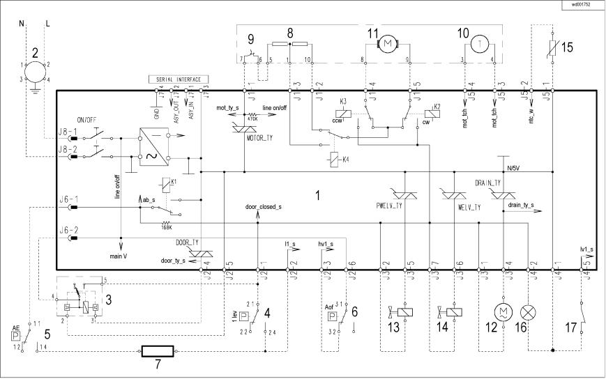
1.7Elementary diagram
1.7.1With instantaneous door locking device
|
|
|
|
|
QUICK GUIDE AND APPLIANCES LIST |
10/176 |
599 72 40-80 |
||
EWM1000
1.8With PTC door locking device
|
|
|
|
|
QUICK GUIDE AND APPLIANCES LIST |
11/176 |
599 72 40-80 |
||
EWM1000
1.8.1Key to circuit diagram
|
Electrical components – appliance |
|
Components of electronic circuit board |
1. |
Circuit board |
DOOR_TY |
Triac for door safety interlock |
2. |
Suppressor |
DRAIN_TY |
Triac for drain pump |
3. |
Main switch (on programme selector) |
K1 |
Heating element relay |
4. |
Door safety interlock |
K2 |
Motor relay: clockwise rotation |
5. |
1st level pressure switch |
K3 |
Motor relay: anti-clockwise rotation |
6. |
Anti-boiling pressure switch |
K4 |
Motor relay: half-range power (certain models only) |
7. |
Anti-overflow pressure switch (certain models only) |
MOTOR_TY |
Motor triac |
8. |
Heating element |
ON/OFF |
Main switch (programme selector) |
9. |
Stator (motor) |
PWELW_TY |
Triac for pre-wash solenoid valve |
10. |
Overload circuit-breaker (motor) |
Serial interface |
Asynchronous serial interface |
11. |
Tachymetric generator (motor) |
WELV_TY |
Triac for washing solenoid valve |
12. |
Rotor (motor) |
|
|
13. |
Drain pump |
|
|
14. |
Pre-wash solenoid valve |
|
|
15. |
Washing solenoid valve |
|
|
16. |
“Door closed” lamp (certain models only) |
|
|
17. |
Drum positioning system (DSP) (top-loaders – certain models only) |
|
|
QUICK GUIDE AND APPLIANCES LIST |
12/176 |
599 72 40-80 |
EWM1000
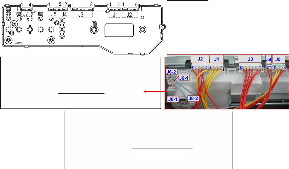
1.9Connectors on circuit board EWM1000
J6 |
|
J2 |
|
J1 |
J3 |
J4 |
J5 |
|
J7 |
J6-1: Heating element |
J2-1 Door safety interlock |
J1-1 |
Motor (triac) |
J3-1 Drain pump (line) |
J4-1 “Door closed” pilot |
J5-1 NTC temperature |
Serial interface: |
||
(relay) |
|
(line-sensing) |
J1-2 |
Motor (stator – full |
J3-2 Solenoids (line) |
lamp |
sensor |
|
|
J6-2: Door safety |
J2-2 1st level(sensing) |
range) |
J3-3 (line) |
J4-2 “Door closed” pilot |
J5-2 NTC temperature |
J7-1 |
ASY_IN |
||
interlock (line) |
J2-3 |
(Anti-overflow |
J1-3 |
Motor (stator - 1/2 |
J3-4 Drain pump (triac) |
lamp |
sensor |
J7-2 |
ASY_OUT |
|
|
pressure switch) |
range) |
J3-5 Pre-wash solenoid |
|
J5-3 Motor (tachymetric |
J7-3 |
5V |
|
J8 |
|
|
|||||||
J2-4 |
Door safety interlock |
J1-4 |
Motor (rotor) |
(triac) |
|
generator) |
J7-4 |
GND |
|
J8-1 line |
|
||||||||
|
(triac) |
J1-5 |
Motor (rotor) |
J3-6 Washing solenoid |
|
J5-4 Motor (tachymetric |
|
|
|
J8-2 line (neutral) |
|
|
|
|
|||||
J2-5 |
(Door safety |
|
|
(triac) |
|
generator) |
|
|
|
|
|
|
|
|
|
||||
|
|
interlock) |
|
|
J3-7 Solenoids (line) |
|
J5-5 (DSP drum |
|
|
|
J2-6 |
(Anti-overflow |
|
|
J3-8 (Not used) |
|
positioning system) |
|
|
|
|
pressure switch) |
|
|
|
|
|
|
|
Rear view
Front view
QUICK GUIDE AND APPLIANCES LIST |
13/176 |
599 72 40-80 |
EWM1000
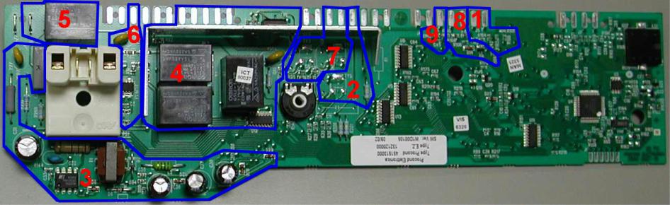
1.10 Burning on the circuit board EWM1000
1.10.1 EWM1000
In case of burning on the main circuit board, check that the problem is not caused by another electrical component (short-circuits, poor insulation, water leakage). Refer to the figures below in order to identify the component that might have caused the burning according to the position of the burned area.
The circuit board shown below is the version with the greatest number of components: other boards may not feature all these components (relay K4 and buzzer).
1.10.2 Components side (common)
1. |
NTC washing temperature sensor |
5. |
Heating element |
2. |
Drain pump |
6. |
Door safety interlock |
3. |
Power supply |
7. |
Water fill solenoids |
4. |
Motor |
8. |
Tachymetric generator (motor) |
|
|
9. |
Drum positioning system (top-loaders) |
|
|
|
|
QUICK GUIDE AND APPLIANCES LIST |
14/176 |
599 72 40-80 |

EWM1000
1.10.3 Pushbutton – led side (horizontal buttons)
1.10.4 Pushbutton – led side (vertical buttons)
1. |
--- |
5. |
Heating element |
2. |
Drain pump |
6. |
Door safety interlock |
3. |
Power supply |
7. |
Water fill solenoids |
4. |
Motor |
8. |
Tachymetric generator (motor) |
|
|
9. |
Drum positioning system (top-loaders) |
|
|
|
|
QUICK GUIDE AND APPLIANCES LIST |
15/176 |
599 72 40-80 |
EWM1000plus EWM2000evo EWM3000new
2 EWM1000plus 2000evo 3000new
2.1Control panel
The configuration of the control panel depends on the following:
ªType of control/display board (with or without display)
ªDesign of the control panel and position of the programme selector (right or left of the buttons)
ªNumber and configuration of the buttons (max. 8)
ªON/OFF switch: incorporated in the programme selector or with separated button
Version with left selector and incorporated ON/OFF button
Alpha-Rim |
|
Sigma |
|
|
|
Club Display
Delta
Version with left selector and button ON/OFF switch
Alpha |
|
Ellipse |
|
|
|
|
|
|
|
|
|
Version with right selector and button ON/OFF switch
Multipanel Built-in
Version with right selector and incorporated ON/OFF switch
|
Sigma/ZK |
AEG NexXxt |
AEG NEW |
|
|
|
|
|
|
|
|
|
|
|
|
|
|
|
|
|
|
|
Club Display |
|
Delta Version without selector and button ON/OFF switch
LCD Version without selector and button ON/OFF switch
LCD Version with left selector and incorporated ON/OFF button
QUICK GUIDE AND APPLIANCES LIST |
16/176 |
599 72 40-80 |
EWM1000plus EWM2000evo EWM3000new
2.2Sigma/Alpha/Ellipse//Multipanel Built-In/Sigma-ZK/Jewel with or without selector
2.2.1Access to diagnostics system
Attention: the programme selector is not always in the position indicated in the picture; it can be on the right or on the left of the display board!
Version with selector and button ON/OFF switch
1.Cancel the set programme and switch the appliance off.
2.Rotate the programme selector of one positions clockwise.
3.Press the start/pause (8) button and any of the option button simultaneously and then, keeping them pressed, switch the appliance on through the ON/OFF button (on/off).
4.Hold the start/pause and option buttons down till the LEDs start flashing (about 5 seconds).
5.To exit the diagnostics system switch the appliance off, on and then off again.
Version with selector and incorporated ON/OFF switch
1.Cancel the set programme switching the appliance off.
2.Press the start/pause (8) button and any of the option buttons simultaneously and then, keeping them pressed, switch the appliance on rotating the programme selector of one position clockwise.
3.Hold the start/pause and option buttons down till the LEDs start flashing (about 5 seconds).
4.To exit the diagnostics system switch the appliance off, on and then off again.
2.2.2Rapid reading of alarm codes
The last alarm code can be displayed even if the programme selector is not in the tenth position (diagnostics) or if the appliance is in normal operating mode (e.g. during the execution of the washing programme):
ªPress and hold down START/PAUSE and the option button nearest to the START/PAUSE button for at least two seconds: the LEDs initially switch off, and then display the flashing sequence corresponding to the alarm; if the display is featured, it will display the alarm code
ªThe alarm sequence is displayed for the time in which the buttons are hold down
ªDuring the time the alarm is displayed, the appliance continues to perform the cycle or, if it is in the selection phase, it keeps in memory the options previously chosen.
2.2.3Cancelling the last alarm
It is good practice to cancel the last alarm, after reading the alarm code to check whether the alarm re-occurs during the diagnostics control after the reparation of the appliance.
1.Select diagnostics mode and turn the programme selector to the tenth position (reading of alarm)
2.Press and hold down START/PAUSE and any of the option buttons at the same time for five seconds.
QUICK GUIDE AND APPLIANCES LIST |
17/176 |
599 72 40-80 |
EWM1000plus EWM2000evo EWM3000new
2.3AEG NexXxt Version with selector and incorporated ON/OFF switch
2.3.1Access to diagnostics system
1.Cancel the set programme and switch the appliance off.
2.Press buttons 1 and 5 (or button 2 and 6) simultaneously and then, holding them down, switch the appliance on by rotating the programme selector of one position clockwise.
3.To exit the diagnostics system switch the appliance off, on and then off again.
2.3.2Rapid reading of alarm codes
The last alarm code can be displayed even if the programme selector is not in the tenth position (diagnostics) or if the appliance is in normal operating mode (e.g. during the execution of the washing programme):
ªPress buttons 1 and 5 simultaneously for at least 2 seconds: the LED switch off and then display the sequence of flashes indicating the alarm.
ªThe alarm sequence is displayed for the time in which the buttons are hold down
ªDuring the time the alarm is displayed, the appliance continues to perform the cycle or, if it is in the selection phase, it keeps in memory the options previously chosen.
2.3.3Cancelling the last alarm
It is good practice to cancel the last alarm, after reading the alarm code to check whether the alarm reoccurs during the diagnostics control after the reparation of the appliance
1.Select diagnostics mode and turn the programme selector to the tenth position (reading of alarm)
2.Press buttons 1 and 5 simultaneously.
3.Hold buttons 1 and 5 down (about 2 seconds).
QUICK GUIDE AND APPLIANCES LIST |
18/176 |
599 72 40-80 |
EWM1000plus EWM2000evo EWM3000new
2.4AEG New Version with right selector and incorporated ON/OFF switch
2.4.1Access to diagnostics system
1.Cancel the set programme and switch the appliance off.
2.Press buttons 1 and 2 simultaneously and then, holding them down, switch the appliance on
by rotating the programme selector of one position clockwise.
3.To exit the diagnostics system switch the appliance off, on and then off again.
2.4.2Rapid reading of alarm codes
The last alarm code can be displayed even if the programme selector is not in the tenth position (diagnostics) or if the appliance is in normal operating mode (e.g. during the execution of the washing programme):
ªPress buttons 1 and 2 simultaneously for at least 2 seconds: the LED switch off and then display the sequence of flashes indicating the alarm.
ªThe alarm sequence is displayed for the time in which the buttons are hold down
ªDuring the time the alarm is displayed, the appliance continues to perform the cycle or, if it is in the selection phase, it keeps in memory the options previously chosen.
2.4.3Cancelling the last alarm
It is good practice to cancel the last alarm, after reading the alarm code to check whether the alarm reoccurs during the diagnostics control after the reparation of the appliance
1.Select diagnostics mode and turn the programme selector to the tenth position (reading of alarm)
2.Press buttons 1 and 2 simultaneously.
3.Hold buttons 1 and 2 down (about 2 seconds).
QUICK GUIDE AND APPLIANCES LIST |
19/176 |
599 72 40-80 |
EWM1000plus EWM2000evo EWM3000new
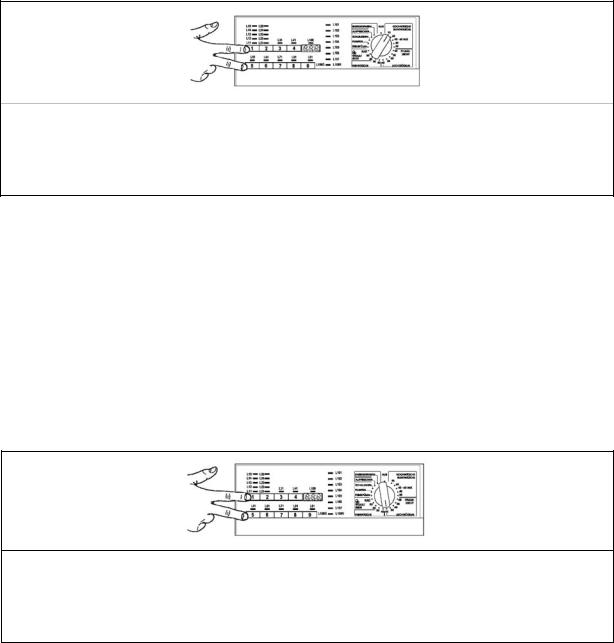
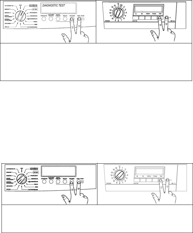
2.5DELTA Version without selector and button ON/OFF switch
2.5.1Access to diagnostics system
1.Reset the set programme with the SKIP/RESET button and then switch the appliance off.
2.Press the START/PAUSE and SKIP/RESET buttons simultaneously and then, holding the buttons down, switch the appliance on using the ON/OFF button.
3.Hold the buttons down until the buzzer sounds and the LEDs start flashing (about 4 seconds).
4.To exit the diagnostics system switch the appliance off, on and then off again.
2.5.2Rapid reading of alarm codes
The last alarm code can be displayed even if the programme selector is not in the tenth position (diagnostics) or if the appliance is in normal operating mode (e.g. during the execution of the washing programme):
ªPress START/PAUSE and SKIP/RESET buttons simultaneously for at least 2 seconds: the LEDs switch off and then display the sequence of flashes indicating the alarm.
ªThe alarm sequence is displayed for the time in which the buttons are hold down
ªDuring the time the alarm is displayed, the appliance continues to perform the cycle or, if it is in the selection phase, it keeps the options previously chosen in memory.
2.5.3Cancelling the last alarm
It is good practice to cancel the last alarm, after reading the alarm code to check whether the alarm reoccurs during the diagnostics control after the reparation of the appliance
1.Select diagnostics mode and Press the Fabrics (1) or Temperature (2) button until LED L10 lights (reading of alarm).
2.Press and hold down START/PAUSE and START/RESET.
QUICK GUIDE AND APPLIANCES LIST |
20/176 |
599 72 40-80 |
EWM1000plus EWM2000evo EWM3000new
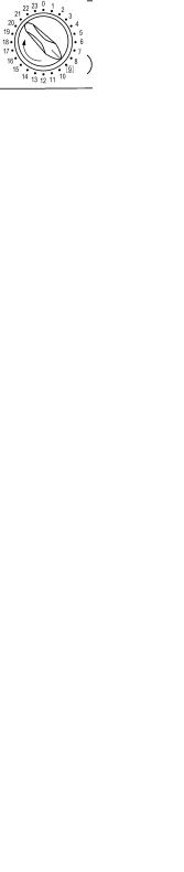
2.6CLUB DISPLAY Version with selector and incorporated ON/OFF switch
2.6.1Access to diagnostics system
1.Cancel the set programme and switch the appliance off.
2.Press buttons 8 and 7 simultaneously, then, holding them down, switch the appliance on rotating the programme selector of one position clockwise.
3.Hold the buttons down up to DIAGNOSTIC MODE appears (about 5 seconds).
4.To exit the diagnostics system switch the appliance off, on and then off again.
2.6.2Rapid reading of alarm codes
The last alarm code can be displayed even if the programme selector is not in the tenth position (diagnostics) or if the appliance is in normal operating mode (e.g. during the execution of the washing programme):
ªFive minutes after the switching on, press and hold down the 8 and 7 buttons simultaneously for 2 seconds, the LCD display shows the last alarm codes (of the main board and display board). The displaying of the alarms depends on the time in which the buttons are hold down.
ªDuring the time the alarm is displayed, the appliance continues to perform the cycle or, if it is in the selection phase, it keeps in memory the options previously chosen.
2.6.3Cancelling the last alarm
It is good practice to cancel the last alarm, after reading the alarm code to check whether the alarm reoccurs during the diagnostics control after the reparation of the appliance
1.Select diagnostics mode and turn the programme selector to the tenth position (reading of alarm)
2.Press simultaneously buttons 8 and 7.
3.Hold them down until the alarms are cancelled.
QUICK GUIDE AND APPLIANCES LIST |
21/176 |
599 72 40-80 |

EWM1000plus EWM2000evo EWM3000new
2.7LCD Version without selector and button ON/OFF switch
2.7.1Access to diagnostics system
1.Reset the set programme and switch the appliance off.
2.Press the 10 and 11 buttons, simultaneously, then, holding them down, switch the appliance on with ON/OFF button.
3.Hold the buttons down till DIAGNOSTIC MODE appears (about 5 seconds).
4.To exit the diagnostic system switch the appliance off, on and then off again.
2.7.2Rapid reading of alarm codes
The last alarm code can be displayed even if the programme selector is not in the tenth position (diagnostics) or if the appliance is in normal operating mode (e.g. during the execution of the washing programme):
ªFive minutes after the switching on, press and hold down the 10 and 11 buttons simultaneously for 2 seconds, the LCD display shows the last alarm codes (of the main board and display board). The displaying of the alarms depends on the time in which the buttons are hold down.
ªDuring the time the alarm is displayed, the appliance continues to perform the cycle or, if it is in the selection phase, it keeps in memory the options previously chosen.
2.7.3Cancelling the last alarm
It is good practice to cancel the last alarm, after reading the alarm code to check whether the alarm reoccurs during the diagnostics control after the reparation of the appliance
1.Select diagnostic mode and with button 4 go to tenth position (alarm reading)
2.Press simultaneously buttons 10 and 11.
3.Hold them down until the alarms are cancelled.
QUICK GUIDE AND APPLIANCES LIST |
22/176 |
599 72 40-80 |
EWM1000plus EWM2000evo EWM3000new
2.8LCD Version with selector and button ON/OFF switch
2.8.1Access to diagnostics system
1.Cancel the set programme and switch the appliance off.
2.Press the start/pause and exit buttons simultaneously, then, holding them down, switch the appliance on rotating the programme selector of one position clockwise.
3.Hold the START/PAUSE and EXIT buttons down up to DIAGNOSTIC MODE appears (about 5 seconds).
4.To exit the diagnostic system switch the appliance off, on and then off again.
2.8.2Rapid reading of alarm codes
The last alarm code can be displayed even if the programme selector is not in the tenth position (diagnostics) or if the appliance is in normal operating mode (e.g. during the execution of the washing programme):
ªFive minutes after the switching on, press and hold down the START/PAUSE and EXIT buttons for 2 seconds, the LCD displaying shows the last alarm codes (of the main board and display board). The displaying of the alarms depends on the time in which the buttons are hold down.
ªDuring the time the alarm is displayed, the appliance continues to perform the cycle or, if it is in the selection phase, it keeps in memory the options previously chosen.
2.8.3Cancelling the last alarm
It is good practice to cancel the last alarm, after reading the alarm code to check whether the alarm reoccurs during the diagnostics control after the reparation of the appliance
1.Select diagnostics mode and turn the programme selector to the tenth position (reading of alarm)
2.Press simultaneously START/PAUSE button and button EXIT (nearest option to START/PAUSE button).
3.Hold down the START/PAUSE and EXIT button until the alarms are cancelled.
QUICK GUIDE AND APPLIANCES LIST |
23/176 |
599 72 40-80 |
EWM1000plus EWM2000evo EWM3000new
2.9Phases of the diagnostics test
Independently of the type of selector, after activating the diagnostics system, the operation diagnostics of the different components and the reading of the alarms can be performed, by rotating the selector clockwise.
In models with digit the code of the selector position is displayed for a second.
In the diagnostics cycle all alarms are activated. If during the cycle operation an alarm occurs, the appliance blocks and the LEDs (and the display) flash indicating the relative code.
|
|
|
Diagnostics phases |
|
|
|
|
Selector |
Only |
Components actioned |
Operating conditions |
Function checked |
Displayed |
|
pushbutton |
parameters (1) |
||||
|
|
|
All the LEDs light in |
|
|
|
|
|
|
|
|
|
|
|
|
|
sequence. When a |
|
Operation of |
|
1 |
|
|
button is pressed, the |
|
Button |
|
|
|
Always activated |
the user |
|||
|
|
corresponding LED |
codification |
|||
|
|
|
|
interface |
||
|
|
|
lights (and the buzzer, if |
|
|
|
|
|
|
|
|
|
|
|
|
|
featured, sounds) |
|
|
|
|
|
|
|
|
|
|
|
|
|
|
Door locked |
Water ducted |
|
|
|
|
|
Water level below |
|
|
|
|
|
Door interlock Washing |
through |
(**)Selection |
|
2 |
|
|
anti-flooding level |
|||
|
|
solenoid |
washing |
position code |
||
|
|
|
Maximum time 5 |
|||
|
|
|
|
compartment |
|
|
|
|
|
|
minutes |
|
|
|
|
|
|
|
|
|
|
|
|
|
Door locked |
Water ducted |
|
|
|
|
|
|
||
3 |
|
|
Door interlock Pre-wash |
Water level below |
through pre- |
(**)Selection |
|
|
anti-flooding level |
wash |
|||
|
|
|
solenoid |
Maximum time 5 |
compartment |
position code |
|
|
|
|
|
||
|
|
|
|
minutes |
(bleach) |
|
|
|
|
Door interlock |
Door locked |
Water ducted |
|
|
|
|
|
|||
|
|
|
Water level below |
|
||
4 |
|
|
through |
(**)Selection |
||
|
|
Pre-wash and wash |
anti-flooding level |
|||
|
|
conditioner |
position code |
|||
|
|
|
solenoids |
Maximum time 5 |
||
|
|
|
compartment |
|
||
|
|
|
|
minutes |
|
|
|
|
|
|
|
|
|
|
|
|
|
Door locked |
Water ducted |
|
|
|
|
|
|
||
|
|
|
|
Water level below |
|
|
|
|
|
Door interlock. |
through |
(**)Selection |
|
5 |
|
|
anti-flooding level |
|||
|
|
Bleach/stains solenoid. |
bleach/stains |
position code |
||
|
|
|
Maximum time 5 |
|||
|
|
|
|
compartment |
|
|
|
|
|
|
minutes |
|
|
|
|
|
|
|
|
|
|
|
|
Door interlock |
Door locked. |
|
|
|
|
|
|
|
||
|
|
|
Washing solenoid if the |
|
|
|
6 |
|
|
Water at 1st level. |
|
(**)Selection |
|
|
|
level of water in the tub is |
Heating |
|||
|
|
Maximum time 10 |
position code |
|||
|
|
|
below 1st level Heating |
min. or up to 90ºC. (*) |
|
|
|
|
|
element. |
|
|
|
|
|
|
|
|
|
|
|
|
|
|
|
|
|
|
|
|
Door interlock. (Washing |
Door locked |
|
|
|
|
|
|
|
||
|
|
|
solenoid if the level of |
Water level at 1st |
|
|
|
|
|
water in the tub is below |
Check for leaks |
(**)Selection |
|
7 |
|
|
1st level). Motor (55 rpm |
level. |
||
|
|
|
clockwise, 55 rpm |
|
from the tub |
position code |
|
|
|
counter-clockwise, 250 |
|
|
|
|
|
|
rpm impulse) |
|
|
|
|
|
|
Door interlock |
Door locked |
Drain and |
|
|
|
|
|
|||
|
|
|
spin; control |
|
||
8 |
|
|
Drain pump Motor up to |
Water level lower |
of congruence |
(**)Selection |
|
|
650 rpm then at |
than anti-boiling |
in closure of |
position code |
|
|
|
|
||||
|
|
|
maximum spin speed |
level for spinning |
level pressure |
|
|
|
|
|
|
switches |
|
|
|
|
|
|
|
|
|
|
|
Drying heater |
|
|
(**) selector |
9 |
|
|
Fan |
Door closed |
Drying |
|
|
|
Condensation solenoid |
position code |
|||
|
|
|
|
|
||
|
|
|
Drain pump |
|
|
|
|
|
|
Motor |
|
|
|
|
|
|
|
|
|
|
QUICK GUIDE AND APPLIANCES LIST |
24/176 |
599 72 40-80 |
EWM1000plus EWM2000evo EWM3000new
10 |
|
|
Reading/cancelling last alarm |
Alarm code |
|
|
|
|
|
11, 12 ...24 |
All LEDs light |
in sequence. Pressing a button the corresponding LED lights (and the Buzzer |
||
sounds, if featured) |
|
|||
|
|
|
||
(*)In most cases, this time is sufficient to check the heating. However, the time can be increased by repeating the phase without draining the water: for a moment to a different phase of the diagnostics cycle and then back to the heating control phase (if the temperature is higher than 80°C, heating does not take place).
(**) See tables of following pages.
(1) Models with Display.
QUICK GUIDE AND APPLIANCES LIST |
25/176 |
599 72 40-80 |
EWM1000plus EWM2000evo EWM3000new
2.10 Reading the alarm codes
In order to read the last alarm code memorized in the EEPROM on the PCB:
with knob
•Enter diagnostics mode
•Irrespective of the type of PCB and configuration, turn the programme selector clockwise to the tenth position.
without knob
•Press the Fabrics (1) or Temperature (2) button until LED L10 lights.
2.10.1 Displaying the alarm
The alarm is displayed by a repeated flashing sequence of the two LEDs (0.4 seconds lit, 0.4 seconds off, with an interval of 2.5 seconds between sequences).
The buzzer (if featured) will sound “bips” in synchronization with the flashing of the LEDs.
•END OF CYCLE LED → indicates the first digit of the alarm code (family)
•START/PAUSE → indicates the second digit of the alarm code (number
within the family)
These two LEDs are featured on all models (though they are configured differently), and flash simultaneously.
Notes:
•The first letter of the alarm code “E” (Error) is not displayed, since this letter is common to all alarm codes.
•The alarm code “families” are shown in hexadecimal; in other words:
→A is represented by 10 flashes
→B is represented by 11 flashes
→...
→F is represented by 15 flashes
•Configuration errors are shown by the flashing of a series of LEDs.
2.10.2 Examples of alarm displays
Example: Alarm E43 will display the following:
•On the display, if featured, E43
•The sequence of four flashes of the End-of-cycle LED indicates the first number E43;
•The sequence of three flashes of the Start/Pause LED indicates the second number E43;
END-OF-CYCLE LED |
|
|
|
START/PAUSE LED |
|
|
|
|||||||
On/Off |
Time |
Value |
On/Off |
Time |
Value |
|||||||||
(Sec.) |
(Sec.) |
|||||||||||||
|
|
|
|
|
|
|
|
|
|
|
|
|||
|
|
|
0.4 |
1 |
|
|
|
|
0.4 |
1 |
|
|||
|
|
|
0.4 |
|
|
|
|
0.4 |
|
|||||
|
|
|
|
|
|
|
|
|
|
|
|
|||
|
|
|
0.4 |
2 |
|
|
|
|
0.4 |
2 |
|
|||
|
|
|
0.4 |
|
|
|
|
0.4 |
|
|||||
|
|
|
|
|
|
|
|
|
|
|
|
|||
|
|
|
0.4 |
3 |
|
|
|
|
0.4 |
3 |
|
|||
|
|
|
0.4 |
|
|
|
|
0.4 |
|
|||||
|
|
|
|
|
|
|
|
|
|
|
|
|||
|
|
|
0.4 |
4 |
|
|
|
|
3,3 |
Pause |
||||
|
|
|
0.4 |
|
|
|
|
|||||||
|
|
|
|
|
|
|
|
|
||||||
|
|
|
2.5 |
Pause |
|
|
|
|
|
|
|
|||
QUICK GUIDE AND APPLIANCES LIST |
26/176 |
599 72 40-80 |

EWM1000plus EWM2000evo EWM3000new
2.11 Table of alarms codes EWM 1000plus EWM2000EVO EWM3000NEW
|
|
|
Action/status of machine |
|
|
Alarm |
Description |
Possible malfunction |
Reset |
||
E00 |
|
No alarm |
|
--- |
|
|
|
Tap closed or water pressure too low; Drain tube improperly positioned; |
|
|
|
E11 |
Poor water fill before wash cycle |
Water fill solenoid valve is defective; Leaks from water circuit on |
Cycle is paused with door locked |
Start |
|
pressure switch; Pressure switch defective; Wiring defective; Main board |
|||||
|
|
defective. |
|
|
|
E12 |
Difficulty in water fill during drying (maximum |
Tap closed or water pressure too low; solenoid valve; pressure switch |
|
|
|
time 3 min. water fill in drying during the wash |
water circuit; pressure switches; wiring; main board. |
Cycle is paused |
Start |
||
|
load unrolling phase) |
|
|
|
|
E13 |
|
Drain tube improperly positioned; Water pressure too low; |
|
|
|
Water leaks |
Water fill solenoid valve is defective; Water circuit on pressure switch is |
Cycle is paused with door locked |
Start |
||
|
|
leaking/clogged; Pressure switch defective. |
|
|
|
|
|
Drain tube kinked/clogged/improperly positioned; Drain filter |
|
|
|
E21 |
Poor draining |
clogged/dirty; Drain pump defective; Pressure switch defective; Wiring |
Cycle is paused |
Start |
|
defective; Main board defective; Electrical current leak between heating |
|||||
|
|
element and ground. |
|
|
|
E22 |
Difficulty in water fill during drying or drying |
Drain hose kinked; filter clogged: drying condenser clogged; drain pump |
|
|
|
condenser clogged (anti-boiling pressure |
faulty; pressure switches faulty; wiring; main circuit board defective; |
Cycle is paused |
Start |
||
|
switch closed on “FULL”) |
current leakage between heater and ground. |
|
|
|
E23 |
Defective triac for drain pump |
Drain pump defective; Wiring defective; Main board defective. |
Emergency drain procedure - Cycle |
OFF/reset |
|
stops with door unlocked |
|||||
|
|
|
|
||
E24 |
Malfunction in sensing circuit on triac for drain |
Main board defective. |
Emergency drain procedure - Cycle |
OFF/reset |
|
|
pump |
|
stops with door unlocked |
|
|
E31 |
Malfunction in pressure switch circuit |
|
|
|
|
(frequency of signal from pressure switch out |
Pressure switch; Wiring; Main board; |
Cycle stops with door locked |
OFF/reset |
||
|
of limits) |
|
|
|
|
|
Electronic pressure switch improperly |
Tap is closed or water pressure is too low; |
|
|
|
|
calibrated (level on electronic pressure switch |
|
|
||
E32 |
Solenoid valve; |
Cycle is paused |
Start |
||
differs from 0-66 mm after initial calibration |
Water circuit on pressure switches; pressure switches; |
||||
|
drain and when antiboiling pressure switch is |
|
|
||
|
Wiring; main board; |
|
|
||
|
on “empty”). |
|
|
|
|
|
Inconsistency between level on electronic |
Pressure switch defective; |
|
|
|
|
Electrical current leak between heating element and ground; Heating |
Emergency drain procedure - Cycle |
|
||
E33 |
pressure switch and level on antiboiling |
OFF/reset |
|||
element; Wiring defective; |
|||||
|
pressure switch 1-2 (fault persists for at least |
Main board defective. |
stops with door unlocked |
|
|
|
60 sec.). |
|
|
||
|
Water circuit; |
|
|
||
|
|
|
|
||
|
Inconsistency between level on electronic |
Pressure switch defective; |
|
|
|
|
Electrical current leak between heating element and ground; Heating |
|
|
||
E34 |
pressure switch and level on antiboiling |
Emergency drain procedure - Cycle |
|
||
element; Wiring defective; |
OFF/reset |
||||
|
pressure switch 2 (fault persists for at least 60 |
Main board defective. |
stops with door unlocked |
|
|
|
sec.). |
|
|
||
|
Water circuit; |
|
|
||
|
|
|
|
QUICK GUIDE AND APPLIANCES LIST |
27/176 |
599 72 40-80 |

EWM1000plus EWM2000evo EWM3000new
|
|
|
Action/status of machine |
|
|
Alarm |
Description |
Possible malfunction |
Reset |
||
E35 |
Overflow |
Water fill solenoid valve is defective; Leaks from water circuit on |
Cycle stops. Emergency drain |
OFF/reset |
|
pressure switch; Pressure switch defective; Wiring defective; Main boardprocedure. Drain pump continues to |
|||||
|
|
defective. |
operate (5 min. on, then 5 min. off, etc.). |
|
|
E36 |
Sensing circuit on antiboiling pressure switch |
Main board defective. |
Cycle stops with door locked |
OFF/reset |
|
|
1 defective |
Electrical current leak between drying heating element and ground |
|
|
|
E37 |
1st level sensing circuit faulty |
PCB faulty. |
Cycle blocked, door locked. |
OFF/reset |
|
E38 |
Pressure chamber blocked |
Pressure switch hydraulic circuit; |
Heating phase skipped. |
--- |
|
(water level does not vary for at least 30 sec. |
Pressure switches; |
||||
|
during drum rotation |
Motor drive belt broken; |
|
|
|
E39 |
“HV” sensor of anti-overflow level faulty |
PCB faulty. |
Cycle blocked, door locked. |
OFF/reset |
|
E3A |
Heating elem. relay sensing faulty |
PCB faulty. |
Cycle blocked, door locked |
OFF/reset |
|
E41 |
Door open |
Door interlock faulty; wiring faulty; |
Cycle paused |
Start |
|
PCB faulty. |
|||||
|
|
|
|
||
E42 |
Problems of door closure |
Door interlock faulty; wiring faulty; |
Cycle paused |
Start |
|
PCB faulty. |
|||||
|
|
|
|
||
E43 |
Interlock power supply triac faulty |
Door interlock faulty; wiring faulty; |
(Safety drain cycle) Cycle blocked |
OFF |
|
PCB faulty. |
|||||
|
|
|
|
||
E44 |
Door interlock sensor faulty |
PCB faulty. |
(Safety drain cycle) Cycle blocked |
OFF |
|
E45 |
Door interlock sensing circuit triac faulty |
PCB faulty |
(Safety drain cycle) Cycle blocked |
OFF |
|
E51 |
Motor power supply triac short-circuited |
PCB faulty; current leakage from motor or from wiring. |
Cycle blocked, door locked (after 5 |
OFF/reset |
|
attempts) |
|||||
|
|
|
|
||
E52 |
No signal from motor tachometric generator |
Motor faulty; wiring faulty; PCB faulty |
Cycle blocked, door locked (after 5 |
OFF/reset |
|
attempts) |
|||||
|
|
|
|
||
E53 |
Motor triac sensing circuit faulty |
PCB faulty. |
Cycle blocked, door locked |
OFF/reset |
|
E54 |
Motor relay contacts sticking |
PCB faulty; current leakage from motor or from wiring |
Cycle blocked, door locked (after 5 |
OFF/reset |
|
attempts) |
|||||
|
|
|
|
||
E57 |
Inverter is drawing too much current (>15A) |
Motor defective; Wiring defective on inverter for motor, inverter board |
Cycle stops with door locked (after 5 |
OFF/reset |
|
defective. |
attempts). |
||||
|
|
|
|||
E58 |
Motor is drawing too much current (>4.5A) |
Motor defective; Wiring defective on inverter for motor, inverter board |
Cycle stops with door locked (after 5 |
OFF/reset |
|
defective, abnormal motor operation (motor overloaded). |
attempts). |
||||
|
|
|
|||
E59 |
No signal from tachometric generator for more |
Motor defective; Wiring defective on inverter for motor; |
Cycle stops with door locked (after 5 |
OFF/reset |
|
|
than 3 seconds |
Inverter board defective. |
attempts). |
|
|
E5A |
|
Inverter board defective. NTC open (on the inverter board). |
Cycle stops with door locked (after 5 |
|
|
Overheating on heat dissipater for inverter |
Overheating caused by continuous operation or ambient conditions (let |
OFF/reset |
|||
attempts). |
|||||
|
|
appliance cool down) |
|
|
|
E5B |
Input voltage is lower than 175V |
Wiring defective, Inverter board defective |
Cycle stops with door locked (after 5 |
OFF/reset |
|
attempts). |
|||||
|
|
|
|
||
E5C |
Input voltage is too high |
Inverter board defective, the mains voltage is too high (measure the |
Cycle stops with door locked (after 5 |
OFF/reset |
|
mains voltage) |
attempts). |
||||
|
|
|
|||
E5D |
Data transfer error between inverter and main |
Line interference, Wiring defective, defective main board or inverter |
Cycle stops with door locked (after 5 |
OFF/reset |
|
|
board |
board |
attempts). |
|
|
QUICK GUIDE AND APPLIANCES LIST |
28/176 |
599 72 40-80 |

EWM1000plus EWM2000evo EWM3000new
|
|
|
Action/status of machine |
|
|
Alarm |
Description |
Possible malfunction |
Reset |
||
E5E |
Communication error between inverter and |
Defective wiring between main board and inverter board, |
Cycle stops |
OFF |
|
|
main board |
Defective inverter board, defective main board |
|
|
|
E5F |
Inverter board fails to start the motor |
Defective inverter board, Defective wiring, defective main board |
Cycle stops with door locked (after 5 |
OFF/reset |
|
attempts). |
|||||
|
|
|
|
||
E61 |
Insufficient heating during wash cycle |
Defective NTC sensor for wash cycle; Heating element defective; Wiring |
Heating phase is skipped |
Start |
|
|
|
defective; Main board defective. |
|
|
|
E62 |
Overheating during wash cycle |
Defective NTC sensor for wash cycle; Heating element defective; Wiring |
Safety drain cycle - Cycle stops with door |
OFF/reset |
|
|
|
defective; Main board defective. |
unlocked |
|
|
E66 |
Relay supplying power to heating element |
Main board defective; Electrical current leak from heating element to |
Safety drain cycle - Cycle stops with door |
OFF/reset |
|
|
defective |
ground. |
unlocked |
|
|
E71 |
NTC sensor for wash cycle defective |
Defective NTC sensor; Wiring defective; |
Heating is skipped |
Start |
|
Main board defective. |
|||||
|
|
|
|
||
E72 |
Fault in NTC sensor on drying condenser |
Drying NTC sensor (condenser) defective; wiring defective; main circuit |
|
|
|
(voltage out of range = short-circuit, open |
Heating is skipped |
Start |
|||
|
circuit) |
board defective. |
|
|
|
|
|
|
|
||
E73 |
Fault in NTC sensor on drying duct (voltage |
Drying NTC sensor (duct) defective; wiring defective; main circuit board |
Heating is skipped |
Start |
|
|
out of range = short-circuit, open circuit) |
defective. |
|
|
|
E74 |
NTC sensor for wash cycle improperly |
NTC sensor improperly positioned; Defective NTC sensor; Wiring |
Heating is skipped |
Start |
|
|
positioned |
defective; Main board defective. |
|
|
|
E82 |
Error in selector reset position |
PCB faulty (Wrong configuration data). Selector, wiring |
--- |
OFF/reset |
|
E83 |
Error in reading selector |
PCB faulty (Wrong configuration data). Selector, wiring |
Cycle cancelled |
--- |
|
E84 |
Recirculation pump defective (inconsistency |
Recirculation pump; |
Machine drains and cycle stops (with |
|
|
between the state of the sensing circuit for the |
Wiring; |
OFF/reset |
|||
door unlocked) |
|||||
|
recirculation pump and the state of the triac) |
Main board; |
|
||
|
|
|
|||
E85 |
Defective sensing circuit on triac for |
|
Machine drains and cycle stops (with |
|
|
recirculation pump (input voltage on |
Main board |
OFF/reset |
|||
door unlocked) |
|||||
|
microprocessor remains at 0 or 5 V). |
|
|
||
|
|
|
|
||
E91 |
Communication error between main board and |
Wiring defective; Control/display board defective |
Cycle stops |
--- |
|
|
display board |
Main board defective. |
|
|
|
E92 |
Inconsistency in communication between main |
Wrong control/display board; |
Cycle stops |
--- |
|
board and display board |
Wrong main board (not right for model). |
||||
|
(versions not compatible) |
|
|
||
|
|
|
|
||
E93 |
Configuration error on appliance |
Main board defective (Improper programming). |
Cycle stops |
OFF/reset |
|
E94 |
Configuration error on wash cycle |
Main board defective (Improper programming). |
Cycle stops |
OFF/reset |
|
E95 |
Communication error between microprocessor |
Main board defective. |
Cycle stops |
OFF/reset |
|
|
and EEPROM |
|
|
|
|
E97 |
Inconsistency between list of programmes and |
Main board defective (Improper programming). |
Cycle stops |
OFF/reset |
|
|
configuration of cycle |
|
|
|
|
E98 |
Communication error between microprocessor |
Display board faulty |
The cycle continues |
----------- |
|
|
and clock |
|
|
|
|
EB1 |
Frequency of power supplied to appliance out |
Problems with the power mains (wrong power/interference); Main board |
Cycle stops |
--- |
|
|
of limits |
defective. |
|
|
QUICK GUIDE AND APPLIANCES LIST |
29/176 |
599 72 40-80 |

EWM1000plus EWM2000evo EWM3000new
|
|
|
Action/status of machine |
|
|
Alarm |
Description |
Possible malfunction |
Reset |
||
EB2 |
Input voltage too high |
Problems with the power mains (wrong power/interference); Main board |
Cycle stops |
--- |
|
|
|
defective. |
|
|
|
EB3 |
Input voltage too low |
Problems with the power mains (wrong power/interference); Main board |
Cycle stops |
--- |
|
|
|
defective. |
|
|
|
EBE |
Inconsistency between safety relay and |
Main board defective, defective wiring |
Machine drains and cycle stops (with |
OFF/reset |
|
|
sensing circuit |
|
door unlocked) |
|
|
EBF |
Sensing circuit on safety system defective |
|
Machine drains and cycle stops (with |
|
|
(input voltage on microprocessor remains at 0 |
Main board defective |
OFF/reset |
|||
door unlocked) |
|||||
|
or 5 V). |
|
|
||
|
|
|
|
||
EC1 |
Solenoid valve inoperative but flow meter |
Main board defective, Solenoid valve defective |
Cycle stops with door locked (after 5 |
OFF/reset |
|
|
operating |
|
attempts). |
|
|
EC2 |
Signal from turbidity sensor out of limits |
Turbidity sensor defective, Main board defective, Wiring defective |
----------------------- |
Start/reset |
|
EC3 |
Signal from weight sensor out of limits |
Weight sensor defective, Main board defective, Wiring defective |
--- |
Start/reset |
|
EF1 |
Drain filter clogged |
Drain tube clogged/kinked/placed too high; |
Warning is displayed at end of cycle |
--- |
|
|
(drain cycle too long) |
Drain filter dirty/clogged. |
(relative LED is lit) |
|
|
EF2 |
Too much detergent |
Too much detergent used; Drain tube clogged/kinked; |
Warning is displayed at end of cycle |
--- |
|
|
(too much foam during drain cycles) |
Drain filter dirty/clogged. |
(relative LED is lit) |
|
|
EF3 |
“Water Control” system tripped |
Water leaks onto base frame; water control system defective. |
Machine drains and cycle stops |
OFF/reset |
|
EF4 |
Water fill pressure too low, no signal from flow |
Tap closed, water pressure too low |
--------------------------- |
Reset |
|
|
meter and solenoid valve is open |
|
|
|
QUICK GUIDE AND APPLIANCES LIST |
30/176 |
599 72 40-80 |
 Loading...