


0297 9929en
Deutz 0297 9929en, F2M 2011, F3M 2011, F4M 2011, BF3M 2011 Operation Manual
...
Operation Manual
2011
22093 Umschlag 16.01.2006 8:16 Uhr Seite 1

● Please read and observe the information
given in this Operation Manual. This will
enable you to avoid accidents, preserve
the manufacturer’s warranty and maintain
the engine in peak operating condition.
● This engine has been built exclusively for
the application specified in the scope of
supply, as described by the equipment
manufacturer and is to be used only for the
intended purpose. Any use exceeding that
scope is considered to be contrary to the
intended purpose. The manufacturer will
not assume responsibility for any damage
resulting therefrom. The risks involved are
to be borne solely by the user.
● Use in accordance with the intended purpose also implies compliance with the conditions laid down by the manufacturer for
operation, maintenance and servicing. The
engine should only be operated by personnel trained in its use and the hazards
involved.
● The relevant accident prevention g uidelines
and other generally accepted safety and
industrial hygiene regulations must be observed.
● When the engine is running, there is a risk
of injury through:
- turning/hot components
- engines with positive ignition
- ignition systems (high electrical voltage)
You must avoid contact at all times!
● Unauthorized engine modifications will invalidate any liability claims against the manufacturer for resultant damage.
Manipulations of the injection and regulating
system may also influence the performance
of t he engine, and its emissions. Adherence
to legislation on pollution c annot be guaranteed under such conditions.
● Do not change, convert or adjust the cooling
air intake area to the blower.
The manufacturer shall n ot be held responsible for any damage which results from
such work.
● When carrying out maintenance/repair operations on the engine, the use of DEUTZ
original parts is prescribed. These are
specially designed for your engine and
guarantee perfect operation.
Non-compliance results in the expiry of the
warranty!
● Maintenance and cleaning of the engine
should only be carried out when the engine
is switched off and has cooled down.
You must ensure that the electrical systems
have been switched off and the ignition
key has been removed.
Accident prevention guidelines concerning
electrical systems (e.g. VDE-0100/-0101/
-0104/-0105 Electrical protective measures
against dangerous touch voltage) are to be
observed.
When cleaning with fluids, all electrical
components are to be covered impermeably.
Safety guidelines / Accident prevention
!
22093 Umschlag 16.01.2006 8:16 Uhr Seite 2

©
2004
Operation manual
2011
0297 9929 en
Engine Serial
Number:
Please enter the engine serial number here.
This number should be quoted when inquiring
about Customer Service, Repairs or Spare
Parts (see Section 2.1).
Te chnical modifications required to improve
our engines are reserved with regard to
specification data and other technical
information contained in this Operation Manual. No parts of this Manual may be
reproduced in any form or by any means
without our written approval.

Foreword
Dear Customer,
Liquid-cooled Deutz engines are designed
for a large number of applications.
Consequently, a wide range of variants is
offered to meet the requirements of specific
cases.
Your engine is appropriately equipped for the
installation concerned, which means that not
all of the components described in this Operation Manual are necessarily fitted to your
engine.
We have endeavoured to highlight any
differences so that you will be able to locate
the operating and maintenance instructions
relevant to your engine quickly and easily.
Please read this Manual before starting your
engine, and always observe the operating
and maintenance instructions.
We are available to help with any additional
inquiries
Sincerely,
DEUTZ AG

Contents
1. General
2.
Engine Description
2.1 Model
2.1.1 Rating Plate
2.1.2 Position of the Rating Plate
2.1.3Engine Serial Number
2.1.4 Cylinder Numbering
2.1.5 Fuel Delivery Lock
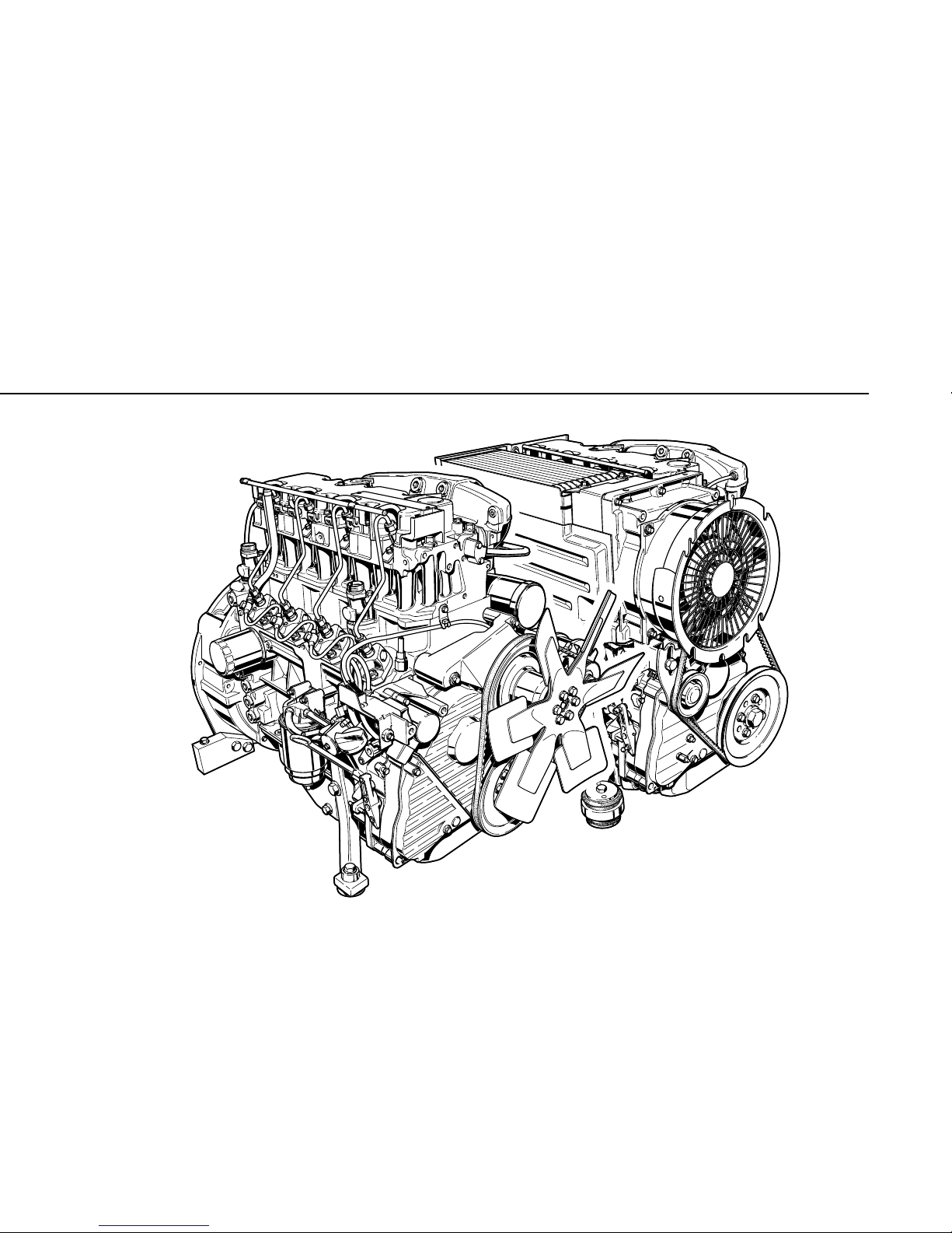
2.2 Engine Illustrations
2.2.1Operation Side:
Example FL 2011
2.2.2 Exhaust Side:
Example FL 2011
2.2.3 Operation Side:
Example BF4L 2011
2.2.4 Exhaust Side:
Example BF4L 2011
2.2.5 Operation Side:
Example FM 2011
2.2.6 Exhaust Side:
Example FM 2011
2.2.7 Operation Side:
Example BFM 2011
2.2.8 Exhaust Side:
Example BFM 2011
2.3 Oil Circuit
2.3.1Lube Oil Circuit Schematic
2.4Fuel System Schematic
2.4.1Fuel System
2.5 Coolant System
2.5.1 Coolant Plan
3. Engine Operation
3.1 Commissioning
3.1.1 Adding Engine Oil
3.1.2 Adding Fuel
3.1.3 Other Preperations
3.1.4 Additional Maintenance Work
3.2 Starting
3.2.1 Electric Starting
3.3 Monitoring Operation
3.3.1 Engine Oil Pressure
3.3.2 Engine Te mperature
3.4 Shutting Off
3.4.1 Mechanical Shut-Off
3.4.2 Electric Shut-Off
3.5 Operating Conditions
3.5.1Winter Operation
3.5.2High Ambient Te mperature, High
Altitude
4. Operating Media
4.1Lube Oil
4.1.1 Quality
4.1.2 Viscosity
4.2 Fuel
4.2.1Quality
4.2.2 Winter-Grade Fuel
5.
Service
5.1 Service Plan
5.2 Scheduled Maintenance Plan
5.3 Maintenance Chart
5.4 Maintenance Work Completed
6. Service and Maintenance
6.1 Lubrication System
6.1.1 Oil Change Intervals
6.1.2 Check Oil Level, Change Engine Oil
6.1.3Changing Oil Filter
6.1.4 Clean/Replace Oil Filter (Cup)
6.2Fuel System
6.2.1 Replace Fuel Filter
6.2.2 Clean/Replace Fuel Filter (Cup)
6.2.3 Clean Stainer of Fuel Filter
6.2.4 Change Fuel Leakage Line
6.3Cooling System
6.3.1Cleaning Intervals
6.4 Combustion Air Filter
6.4.1Cleaning Intervals
6.4.2 Emptying Cyclone-Type Precleaner
6.4.3 Dry Type Air Cleaner
6.5 Belt Drives
6.5.1 Check V-belt
6.5.2 Te nsioning Alternator Belts
6.5.3 Changing Alternator Belts
6.6 Adjustments
6.6.1 Check Valve Clearance, adjust if
necessary
6.6.1.1Valve Clearance Adjustment
Schematic
6.7 Accessories
6.7.1 Battery
6.7.2 Rotary Current Alternator
6.7.3Transportation Shackles
6.8 Engine Cleaning
6.8.1 Engine Cleaning

©
2004
Contents
7. Faults, Causes and
Remedies
7.1 Fault Table
8.
Engine Preservation
8.1 Preservation
8.1.1Preserving Engine
8.1.2Removing Engine Preservatives
9. Technical Specification
9.1 Engine Specifications and Settings
9.2 To rque Wrench Settings
9.3 To ols
10. Service
©
2004
1
©
200
4
General
DEUTZ Diesel Engines
are the product of many years of research
and development. The resulting know-how,
coupled with stringent quality standards,
guarantee their long service life, high reliability
and low fuel consumption.
It goes without saying that DEUTZ Diesel
Engines meet the highest standards for environmental protection.
Service
Please contact one of our authorized service
representatives in the event of breakdowns
or for spare parts inquiries. Our trained
specialists will carry out repairs quickly and
professionally, using only genuine spare
parts.
Original parts from DEUTZ AG are always
produced in accordance with state-of-theart technology.
Please turn to the end of this manual for
further service information.
!
Care and Maintenance
Sound care and maintenance practices will
ensure that the engine continues to meet the
requirements placed on it. Recommended
service intervals must be observed and
service and maintenance work carried out
conscientiously.
Special care should be taken under abnormally
demanding operating conditions.
Asbestos
DEUTZ original parts are
asbestos-free.
Safety
This symbol i s used for all safety
warnings. Please follow them
carefully. The attention of
operating personnel should be
drawn to these safety
instructions. General safety and accident
prevention regulations laid down by law must
also be observed.
Beware of Running Engine
Shut the engine down before carrying out
maintenance or repair work. Ensure that the
engine cannot be accidentally started. Risk of
accidents.
When the work is complete, be sure to refit
any panels and guards that may have been
removed.
Never fill the fuel tank while the engine is
running.
Observe industrial safety regulations when
running the engine in an enclosed space or
underground.
California
Proposition 65 Warning
Diesel engine exhaust and some of its
constituents are known to the State of
California to cause cancer, birth defects,
and other reproductive harm.

2
©
2004
Engine Description
2.1
Model
2.2
Engine Illustrations
2.3 Lube Oil Circuit Schematic
2.4 Fuel System Schematic
2
©
2004
C
©
31 864 0
© 26 332 2
A
B
©
31 865 0
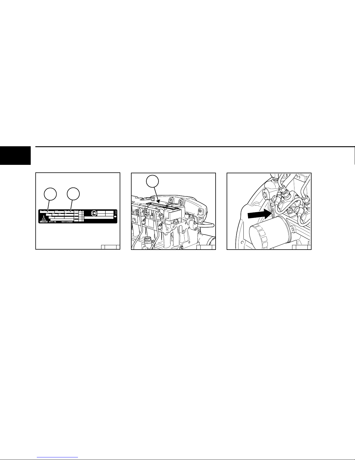
Engine Description 2.1 Model
2.1.1
Rating P
late
The model A , the engine serial number B and
the performance data are stamped on the
rating plate.
The model and engine serial number must be given
when ordering parts.
2.1.2
Position
of the Rating Plate
The rating plate C is attached to the valve
cover.
2.1.3
Engine
Serial Number
The engine serial number B is stamped on
the crankcase D as well as the rating plate.
2
©
2004
!
1234
©
26 431
0
©
26 387
0
2.1 Model Engine Description
2.1.4
Cylinder
Numbering
Cylinders are numbered consecutively,
beginning at the flywheel.
2.1.5
Fuel
Delivery Lock
The manufacturer shall not be held liable for
damages resulting from adjustments made
to the regulator by the operator.
The lock screws are protected in order to
prevent this:
1. with locking paint on model:
with torque balancer
2.with plastic protective cap on model:
without torque balancer.
Adjustments to the regulator
are to be carried out only by
authorised DEUTZ SERVICE
specialists
2
©
2004
© 31 873 1
1
2
3
4
5
7
6
16
15
21
20
19
18
17
9 81214 13 11 10
Engine Description 2.2 Engine Illustration
2.2.1
Operation
Side
FL 2011
1Oil filler neck (valve-gear housing cover)
2 Charge-air line / air-intake line
3 Fan with integrated generator
4 Narrow V-belt
5Tractive electromagnet
6 Wheel-house cover
7 V-belt pulley on crankshaft
8 Oil pan
9Shut-off lever
10 Speed control lever
11 Oil dipstick
12 Oil drain plug
13 Crankcase
14 Oil fill point (on side of crankcase)
15 Fuel pump
16 Easy-change fuel filter
17 Connecting facility for oil heater
18 Lube oil replacement filter
19 Removable coolant intake hood
20 Injection pumps
21 Oil cooler
2
©
2004
© 31 874 1
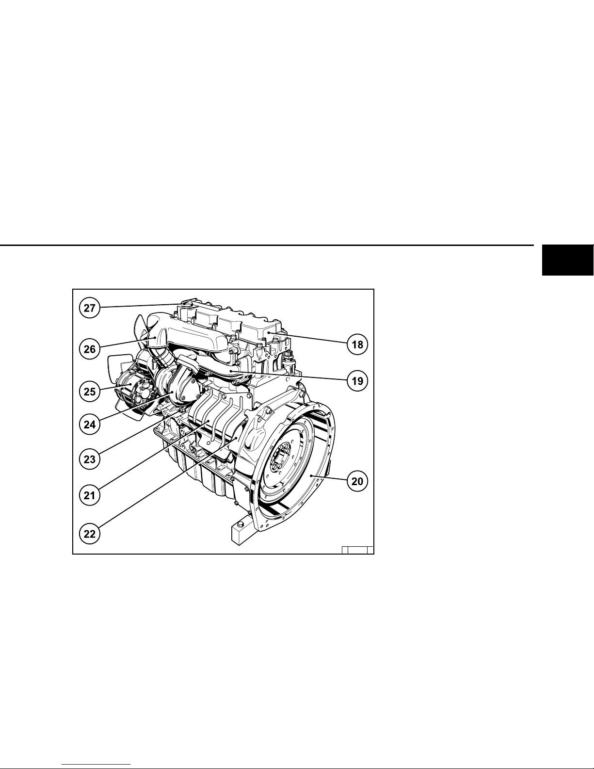
2.2 Engine Illustration Engine Description
2.2.2
Exhaust
Side
FL 2011
22 Date plate
23 Optional attachment of an SAE housing
24 Flywheel with ring gear
25 Starter
26 Front cover
27 Crankcase
28 Exhaust manifold
29 Air intake pipe
22
24
23
29
28
27
26
26
2
©
2004
© 31869 2
Engine Description 2.2 Engine Illustration
2.2.3
Operation
Side
Example: BF4L 2011
1Oil filler neck (valve-gear housing cover)
2 Charge-air line / air-intake line
3 Fan with integrated generator
4 Narrow V-belt
5Tractive electromagnet
6 Wheel-house cover
7 V-belt pulley on crankshaft
8 Oil pan
9Shut-off lever
10 Speed control lever
11 Oil dipstick
12 Crankcase
13 Oil fill point (on side of crankcase)
14 Fuel pump
15 Easy-change fuel filter
16 Connecting facility for oil heater
17 Charge-pressure-dependent full-load stop
(CPD)
18 Lube oil replacement filter
19 Removable coolant intake hood
20 Injection pumps
21 Oil cooler
2
©
2004
© 31 868 1
22
23
24
26
28
30
27
29
31
32
25
2.2 Engine Illustration Engine Description
2.2.4
Exhaust
Side
Example: BF4L 2011
22 Cylinder head
23 Exhaust manifold line
24 Flywheel with ring gear
25 Starter
26 Crankcase
27 Lube oil feed line to turbocharger
28 Lube oil return line from turbocharger
29 Induction pipe
30 Turbocharger (TC)
31 Intake manifold
32 Charge-air line
2
©
2004
©
31 875 3
Engine Description 2.2 Engine Illustration
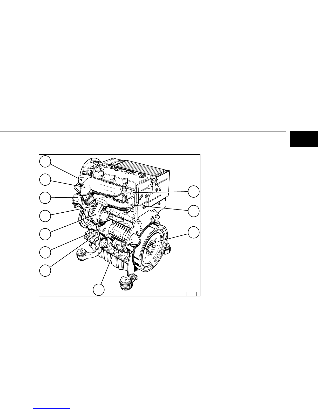
2.2.5 Operation Side
FM 2011
1Oil filler neck (valve-gear housing cover)
2 Charge-air line / air-intake line
3 Alternator
4 Narrow V-belt
5 Tractive electromagnet
6 Timing belt cover
7 V-belt pulley on crankshaft
8 Oil pan
9 Shut-off lever
10 Speed control lever
11 Oil dipstick
12 Oil drain plug
13 Oil fill point (on side of crankcase)
14 Fuel pump
15 Easy-change fuel filter
16 Connecting facility for oil heater
17 Lube oil replacement filter
18 Injection pump(s)
19 Oil cooler connection
20 Injection valve(s)
Xfuel to run line
Yfuel back run line
2
©
2004
©
31876 2
2.2 Engine Illustration Engine Description
2.2.6
Exhaust Side
FM 2011
21 Cylinder head
22 Exhaust manifold
23 Flywheel with ring gear
24 Starter
25 Starter guard (optional)
26 Crankcase
27 Air intake pipe
2
©
2004
© 31 8 61 3
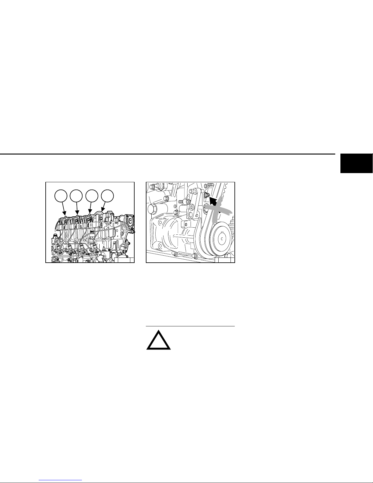
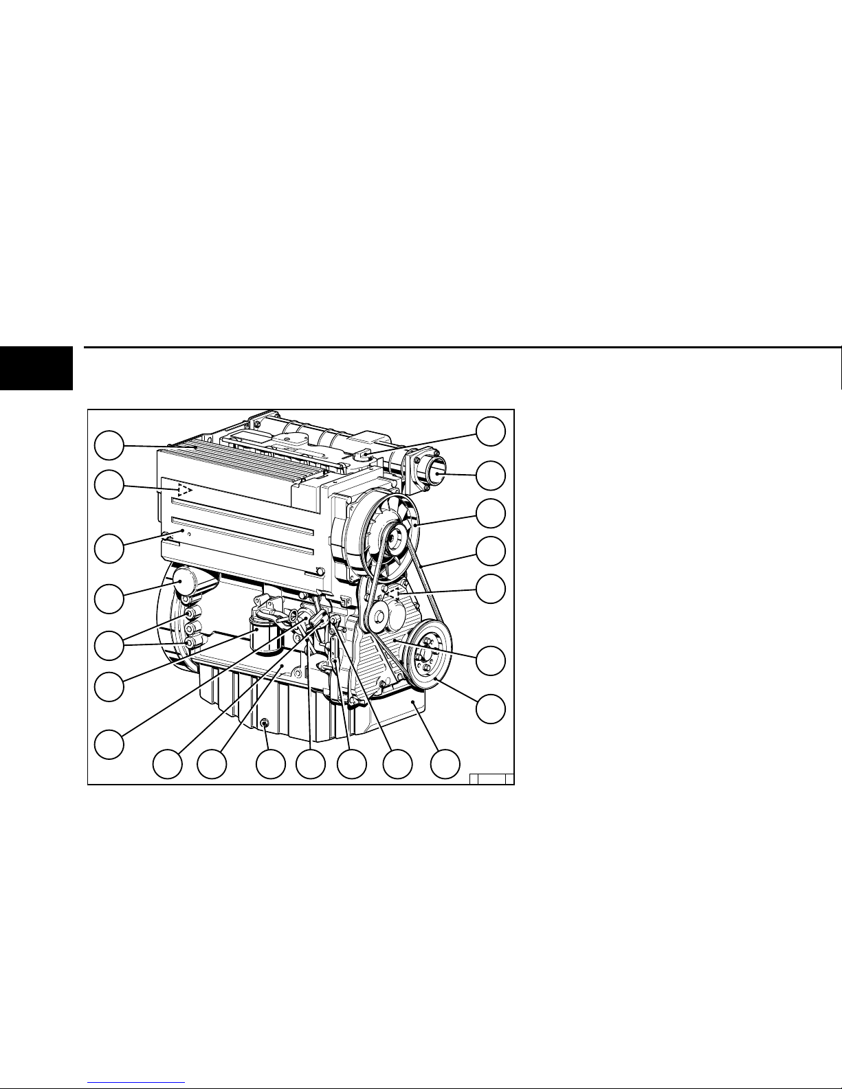
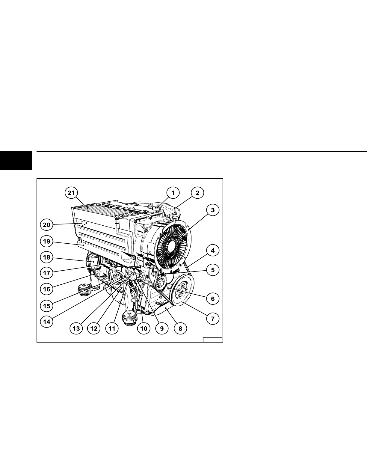
Engine Description 2.2 Engine Illustration
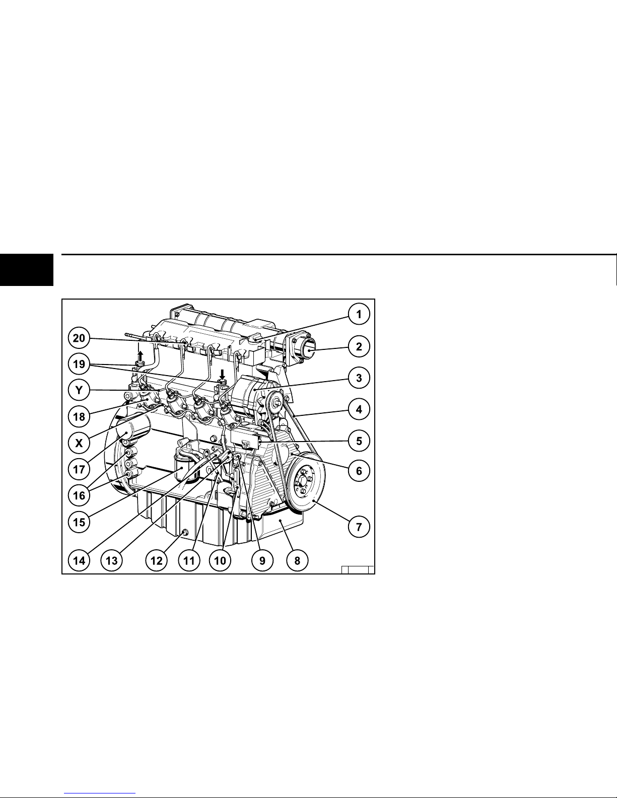
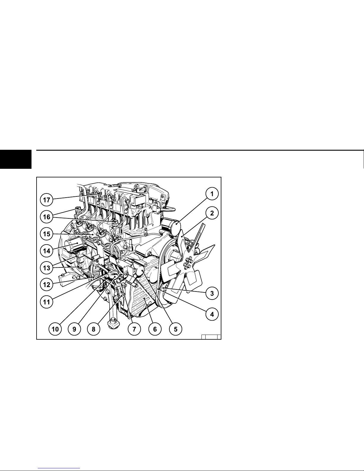
2.2.7
Operation Side
BFM 2011
1 Air-intake pipe
2 Fan wheel
3 V-belt pulley on crankshaft
4 Narrow V-belt
5 Tractive electromagnet
6 Timing belt cover
7 Shut-off lever
8 Speed control lever
9 Oil fill point (on side of crankcase)
10 Oil dipstick
11 Fuel pump
12 Easy-change fuel filter
13 Connecting facility for oil heater
14 Lube oil replacement filter
15 Injection pump(s)
16 Oil cooler connection
17 Injection valve(s)
2
©
2004
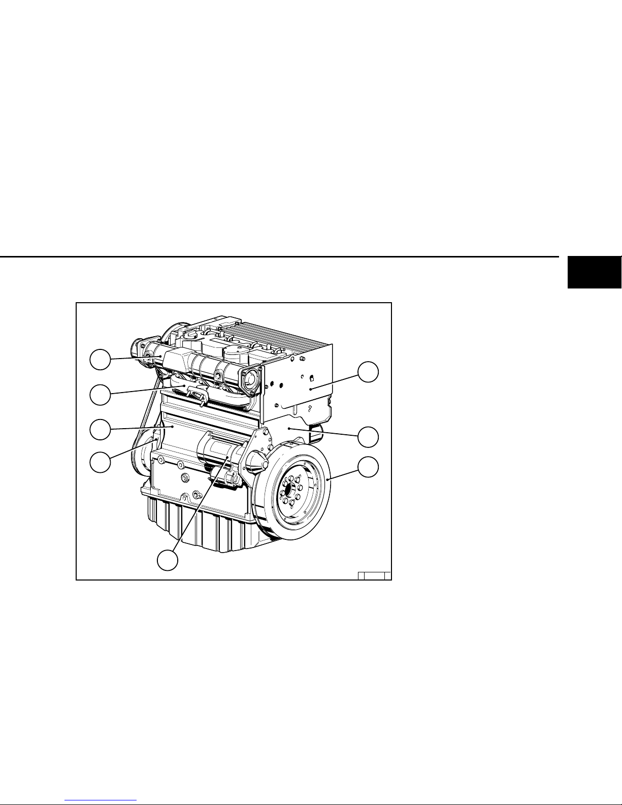
2.2 Engine Illustration Engine Description
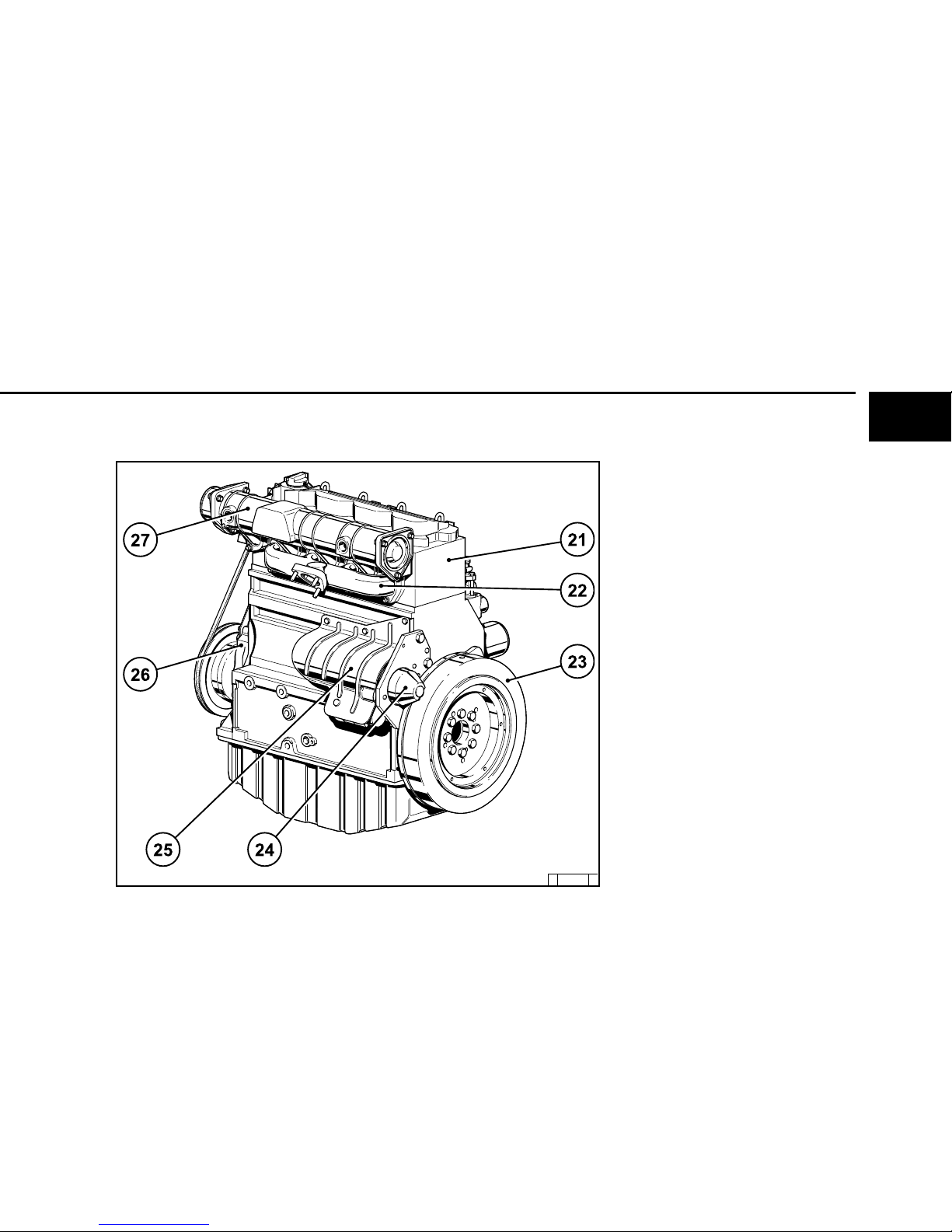
2.2.8
Exhaust Side
BFM 2011
18 Crankcase ventilation (optional)
19 Cylinder head cover
20 Exhaust manifold
21 SAE housing
22 Starter
23 Crankcase
24 Turbocharger
25 Generator with cover
26 Charge-air line
27 Oil filler neck
© 31 862 3
2
©
2004
© 31877 2
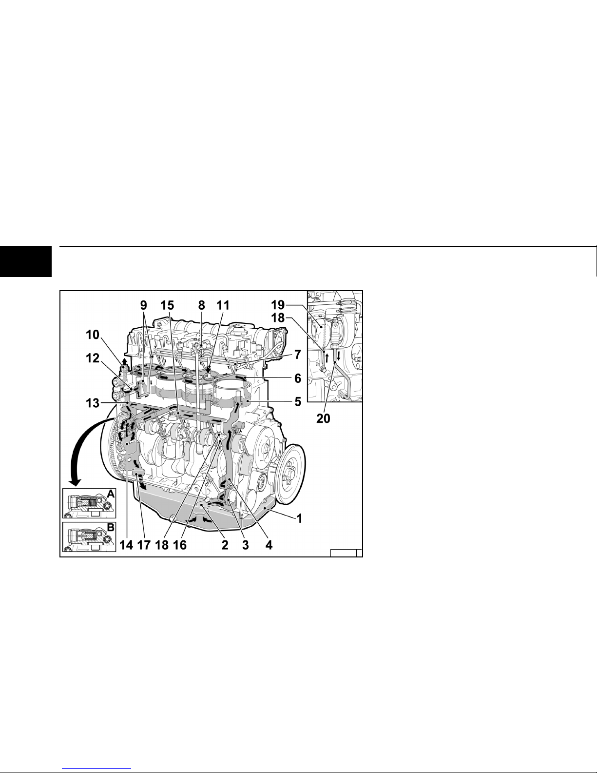
Engine Description 2.3 Oil Circuit
2.3.1
Lube Oil Circuit Schematic
1Oil pan
2Oil-intake pipe
3Oil pump
4Main oil duct
5Oil-cooled cylinders
6Cylinder head cooling neck
7Oil duct for rocker arm lubrication
8Rocker arm
9Oil manifold for the thermostat
10 Intake to external engine oil cooler
11 Return from external engine oil cooler
12 Thermostat h ousing with slide thermostat
13 Oil duct to oil filter
14 Oil filter
15 Oil duct to cam, con-rod and crankshaft
bearings
16 Spray nozzle for piston cooling
17 Oil return via crankcase to oil pan
18 Lube oil intake to turbocharger
19 Turbocharger
20 Return from turbocharger to oil pan
Oil filter console with integrated switching
valve for the control o f the hydraulic tappets
(arrow)
Aengine is cold (around an early adjustment
of the beginning of delivery to reach,
the pistons in the pump tappet with oil
become ge feed)
Bengine is warm
2
©
2004
©
31 863 2
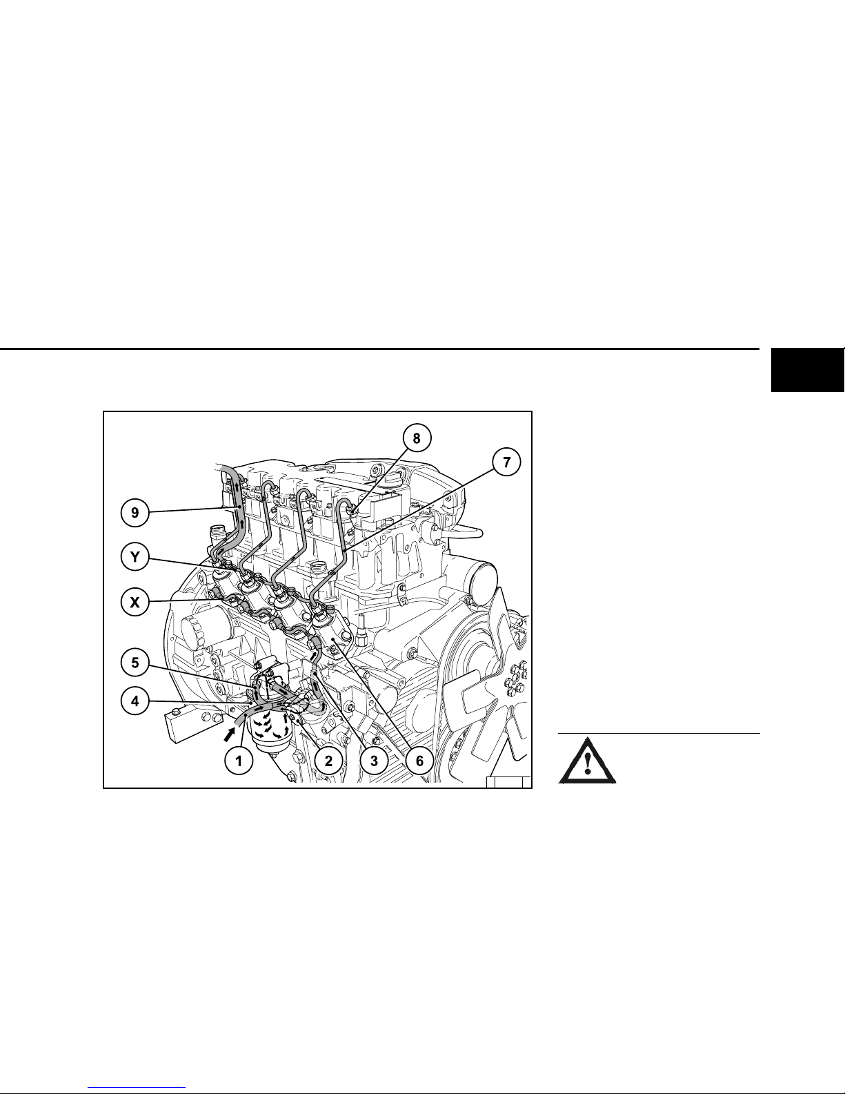
2.4 Fuel System Schematic Engine Description
2.4.1
Fuel System
1 Fuel line from tank to fuel pump
2 Fuel pump
3 Fuel line from fuel pump to easy-change fuel
filter
4Easy-change fuel filter
5Fuel line from filter to injection pump
6 Injection pump
7 Fuel distributor line
8 Injection line
9 Injection valves
xFuel overflow pipe
yFuel return line to tank
The installation of a fuel pre-filter/
hand pump between the fuel tank
and the engine is prescribed to
protect the engines against dirt in
the fuel.

2
©
2004

3
3
©
2004
Engine Operation
3.1 Commissioning
3.2 Starting
3.3
Monitoring Operation
3.4
Shutting Off
3
©
2004
OIL
3.1.1.2 Initial Engine Oil Fill-Up
B/FM 2011
© 26 432 0
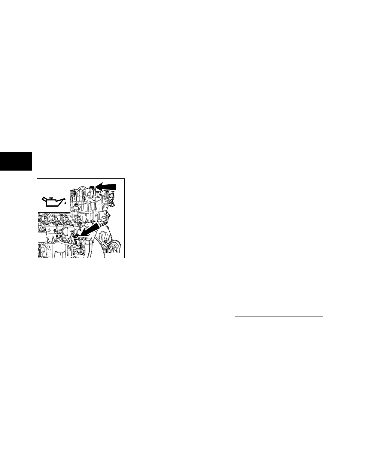
Engine Operation
3.1 Commissioning
3.1.1 Adding Engine Oil
As a rule, engines are delivered without oil.
Pour lube oil into the oil filler neck (arrow).
For oil grade and viscosity, see 4.1.
● Fill oil into oil pan up to "Max." mark on engine
dipstick (for oil quantity see 9.1).
● Start engine and allow to run at low idling
speed for approx. 2 mins.
● Switch off engine.
● Check oil level, if necessary, top up oil to "Max."
mark.
● Fill oil into oil pan up to "Min." mark on engine
dipstick.
● In addition, top up oil quantity of supply
hoses and of external oil cooler (according
to manufacturer’s specifications).
● Allow engine to run warm until thermostat opens
(at approx. 95°C).
● Allow engine to run for approx. 2 mins.
● Switch off engine.
● Check oil level, and if necessary, top up oil to
"Max." mark.
3.1.1.1 Initial Engine Oil Fill-Up
forB/FL 2011
If the person operating the engine does not run up
the engine until the thermostat opens, the oil level
may lie above the "Max." mark on the engine
dipstick when delivered. The level can then only be
assessed after the engine has been run up.
3
3
©
2004
FUEL
!
© 26 398 0
3.1 Commissioning Engine Operation
3.1.1.3 Initial Engine Oil Fill-Up
B/FM 2011 Genset Engine
● Fill oil into oil pan up to "Max." mark on engine
dipstick (for oil quantity see 9.1).
● Start engine and allow to run at low idling speed
for approx. 2 mins.
● Switch off engine.
● Check oil level and fill up with oil up to upper
"Max." mark.
3.1.2 Adding Fuel
Use only commercial-grade diesel fuel. For fuel
grade, see 4.2. Use summer or winter-grade fuel,
depending on the ambient temperature.
Never fill the tank while the engine
is running.
Ensure cleanliness!
Do not spill fuel!

3
©
2004
Engine Operation 3.1 Commissioning
3.1.3 Other Preparations
● Check battery and cable connectors,
see 6.7.1.
● Tr ansport hooks
Remove if fitted (see 6.7.3)
● Tr ial run
After engine has been prepared, let it run for
about 10 minutes without being loaded.
During and after trial run
-Check engine for leaks.
After engine has been turned off
-Check oil level,
see 6.1.2.
Top up with oil, if necessary,
see 3.1.1.
-Retension V-belt,
see 6.5).
3.1.4 Additional Maintenance Work
When commissioning new and reconditioned engines, the following additional maintenance work
must be carried out:
● Change lube oil,
see 6.1.1. + 6.1.2.
● Change oil filter cartridge,
see 6.1.3.
● Change fuel filter cartridge,
see 6.2.1.
● Check V-belts and retension as necessary,
see 6.5.
● Check engine for leaks
● Check engine mounts, retighten if necessary,
see 9.2.
● Check valve clearance, adjust if necessary,
see 5.1. + 6.6.1.
 Loading...