


AV SURROUND RECEIVER
AVR-1306
OPERATING INSTRUCTIONS
BEDIENUNGSANLEITUNG
MODE D’EMPLOI
ISTRUZIONI PER L’USO
INSTRUCCIONES DE OPERACION
GEBRUIKSAANWIJZING
BRUKSANVISNING
|
|
|
|
SVENSKA NEDERLANDS |
ESPAÑOL |
ITALIANO |
FRANCAIS |
DEUTSCH |
ENGLISH |
|||||||||||||||||
|
|
|
CAUTION |
|
NOTE ON USE / HINWEISE ZUM GEBRAUCH / |
|
|
|
|
|
|
|
||||||||||||||
|
|
|
|
OBSERVATIONS RELATIVES A L’UTILISATION / NOTE SULL’USO / |
|
|||||||||||||||||||||
|
|
RISK OF ELECTRIC SHOCK |
|
NOTAS SOBRE EL USO / ALVORENS TE GEBRUIKEN / OBSERVERA |
||||||||||||||||||||||
|
|
|
DO NOT OPEN |
|
|
|
|
|
|
|
|
|
|
|
|
|
|
|
|
|
|
|
|
|
||
CAUTION: TO REDUCE THE RISK OF ELECTRIC SHOCK, DO NOT |
|
|
|
|
|
|
|
|
|
|
|
|
|
|
|
|
|
|
|
|
||||||
|
|
REMOVE COVER (OR BACK). NO USER-SERVICEABLE |
|
|
|
|
|
|
|
|
|
|
|
|
|
|
|
|
|
|
|
|
||||
|
|
PARTS INSIDE. REFER SERVICING TO QUALIFIED |
|
|
|
|
|
|
|
|
|
|
|
|
|
|
|
|
|
|
|
|
||||
|
|
SERVICE PERSONNEL. |
|
|
|
|
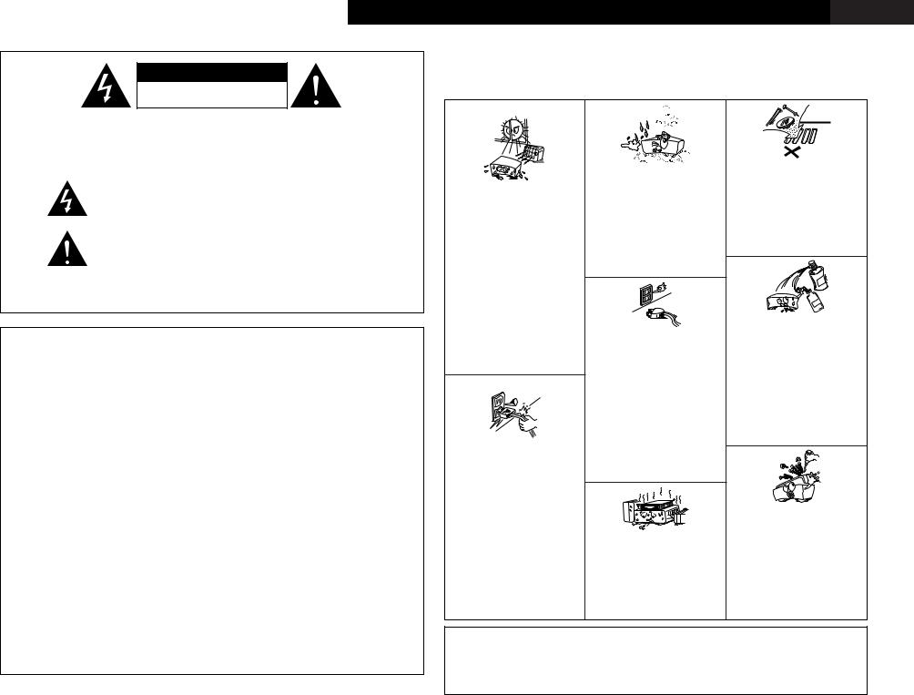
• Keep the apparatus free from moisture, |
• Do not let foreign objects into the apparatus. |
||||||||||||||||||
|
|
The lightning flash with arrowhead symbol, within an equilateral triangle, |
|
|
|
• Keine fremden Gegenstände in das Gerät |
||||||||||||||||||||
|
|
|
|
|
water, and dust. |
|
|
|
|
|
kommen lassen. |
|
|
|
|
|||||||||||
|
|
is intended to alert the user to the presence of uninsulated “dangerous |
|
|
|
• Halten |
Sie |
das |
Gerät von Feuchtigkeit, |
• Ne pas laisser des objets étrangers dans |
||||||||||||||||
|
|
• Avoid high temperatures. |
|
Wasser und Staub fern. |
|
|
|
l’appareil. |
|
|
|
|
|
|||||||||||||
|
|
voltage” within |
the product’s enclosure that may be of sufficient |
|
|
|
|
|
|
|
|
|
||||||||||||||
|
|
|
• Protéger l’appareil contre l’humidité, l’eau |
• E’ importante che nessun oggetto è inserito |
||||||||||||||||||||||
|
|
Allow for sufficient heat dispersion when |
||||||||||||||||||||||||
|
|
magnitude to constitute a risk of electric shock to persons. |
|
et lapoussière. |
|
|
|
|
|
all’interno dell’unità. |
|
|
|
|||||||||||||
|
|
|
installed in a rack. |
|
|
|
|
|
|
|
|
|
|
|||||||||||||
|
|
|
|
|
• Tenete |
l’unità |
|
lontana |
dall’umidità, |
• No deje objetos extraños dentro del equipo. |
||||||||||||||||
|
|
|
|
|
|
• Vermeiden Sie hohe Temperaturen. |
|
|||||||||||||||||||
|
|
|
|
|
|
dall’acqua e dalla polvere. |
|
|
|
• Laat geen |
vreemde voorwerpen |
in |
dit |
|||||||||||||
|
|
|
|
|
|
Beachten Sie, daß |
eine |
ausreichend |
|
|
|
|||||||||||||||
|
|
The exclamation point within an equilateral triangle is intended to alert the |
• Mantenga el equipo libre de humedad, agua |
apparaat vallen. |
|
|
|
|
||||||||||||||||||
|
|
Luftzirkulation gewährleistet |
wird, wenn |
|
|
|
|
|||||||||||||||||||
|
|
y polvo. |
|
|
|
|
|
|
|
• Se till att främmande föremål inte tränger in |
||||||||||||||||
|
|
user to the presence of important operating and maintenance (servicing) |
das Gerät auf ein Regal gestellt wird. |
|
|
|
|
|
|
|
||||||||||||||||
|
|
• Laat geen vochtigheid, water of stof in het |
i apparaten. |
|
|
|
|
|
||||||||||||||||||
|
|
• Eviter des températures élevées |
|
|
|
|
|
|||||||||||||||||||
|
|
instructions in the literature accompanying the appliance. |
|
Tenir compte d’une dispersion de chaleur |
apparaat binnendringen. |
|
|
|
|
|
|
|
|
|
|
|||||||||||
|
|
|
• Utsätt inte apparaten för fukt, vatten och |
|
|
|
|
|
|
|
||||||||||||||||
|
|
|
|
|
|
suffisante lors de l’installation sur une |
damm. |
|
|
|
|
|
|
|
|
|
|
|
|
|
|
|
||||
|
|
|
|
|
|
étagère. |
|
|
|
|
|
|
|
|
|
|
|
|
|
|
|
|
|
|||
WARNING: TO REDUCE THE RISK OF FIRE OR ELECTRIC SHOCK, DO |
|
|
|
|
|
|
|
|
|
|
|
|
|
|
|
|
|
|
|
|||||||
• Evitate di esporre l’unità a temperature alte. |
|
|
|
|
|
|
|
|
|
|
|
|
|
|
|
|
|
|||||||||
Assicuratevi che ci sia un’adeguata |
|
|
|
|
|
|
|
|
|
|
|
|
|
|
|
|
|
|||||||||
|
|
NOT EXPOSE THIS APPLIANCE TO RAIN OR MOISTURE. |
dispersione del calore quando installate |
|
|
|
|
|
|
|
|
|
|
|
|
|
|
|
|
|
||||||
|
|
l’unità in un mobile per componenti audio. |
|
|
|
|
|
|
|
|
|
|
|
|
|
|
|
|
|
|||||||
|
|
|
|
|
|
|
|
|
|
|
|
|
|
|
|
|
|
|
|
|
|
|
||||
|
|
|
|
|
|
• Evite altas temperaturas |
|
|
|
|
|
|
|
|
|
|
|
|
|
|
|
|
|
|
||
|
|
|
|
|
|
Permite la suficiente |
dispersión del calor |
|
|
|
|
|
|
|
|
|
|
• Do not |
let |
insecticides, benzene, |
and |
|||||
|
|
|
|
|
|
cuando está instalado en la consola. |
|
|
|
|
|
|
|
|
|
|
||||||||||
|
|
|
|
|
|
|
|
|
|
|
|
|
|
|
|
thinner come in contact with the apparatus. |
||||||||||
• DECLARATION OF CONFORMITY |
|
• DECLARACIÓN DE CONFORMIDAD |
• Vermijd hoge temperaturen. |
|
|
|
|
|
|
|
|
|
|
|
||||||||||||
|
|
• Unplug the power cord when not using the |
• Lassen Sie das Gerät nicht mit Insektiziden, |
|||||||||||||||||||||||
|
Zorg voor een degelijk hitteafvoer indien het |
|||||||||||||||||||||||||
We declare under our sole responsibility that this |
Declaramos bajo nuestra exclusiva responsabilidad |
apparatus for long periods of time. |
|
Benzin |
oder |
Verdünnungsmitteln |
in |
|||||||||||||||||||
apparaat op een rek wordt geplaatst. |
nicht |
|||||||||||||||||||||||||
product, to |
which |
this declaration relates, is in |
que este producto al que hace |
referencia esta |
• Undvik höga temperaturer. |
|
• Wenn |
das |
Gerät |
eine längere |
Zeit |
Berührung kommen. |
|
|
|
|||||||||||
|
verwendet |
werden |
soll, trennen Sie das |
• Ne pas mettre en contact des insecticides, |
||||||||||||||||||||||
Se till att det finns |
möjlighet till god |
|||||||||||||||||||||||||
conformity with the following standards: |
declaración, está conforme con |
los siguientes |
Netzkabel vom Netzstecker. |
|
|
du benzène et un diluant avec l’appareil. |
||||||||||||||||||||
värmeavledning vid montering i ett rack. |
|
|
||||||||||||||||||||||||
EN60065, EN55013, EN55020, EN61000-3-2 and |
estándares: |
|
• Débrancher |
|
le |
cordon |
d’alimentation |
• Assicuratevvi che l’unità non venga in |
||||||||||||||||||
|
|
|
|
|
||||||||||||||||||||||
EN61000-3-3. |
|
|
EN60065, EN55013, EN55020, EN61000-3-2 y |
|
|
|
lorsque l’appareil n’est pas utilisé pendant |
contatto con insetticidi, benzolo o solventi. |
||||||||||||||||||
|
|
|
|
|
de longues périodes. |
|
|
|
• No permita el contacto de insecticidas, |
|||||||||||||||||
Following the provisions of 73/23/EEC, 89/336/EEC |
EN61000-3-3. |
|
|
|
|
• Disinnestate il filo di alimentazione quando |
gasolina y diluyentes con el equipo. |
|
|
|||||||||||||||||
and 93/68/EEC Directive. |
|
Siguiendo las provisiones de |
las Directivas |
|
|
|
avete l’intenzione di non usare il filo di |
• Laat geen insektenverdelgende middelen, |
||||||||||||||||||
• ÜBEREINSTIMMUNGSERKLÄRUNG |
|
73/23/EEC, 89/336/EEC y 93/68/EEC. |
|
|
|
alimentazione |
per |
un lungo |
periodo di |
benzine of verfverdunner met dit apparaat |
||||||||||||||||
|
|
|
|
tempo. |
|
|
|
|
|
|
|
|
in kontakt komen. |
|
|
|
||||||||||
|
|
|
|
|
|
|
|
|
|
|
|
|
|
|
|
|
||||||||||
Wir erklären unter unserer Verantwortung, daß |
• EENVORMIGHEIDSVERKLARING |
|
|
|
• Desconecte el cordón de energía cuando no |
• Se till att inte insektsmedel på spraybruk, |
||||||||||||||||||||
dieses Produkt, auf das sich diese Erklärung |
Wij verklaren uitsluitend op onze verantwoordelijkheid |
|
|
|
utilice el equipo por mucho tiempo. |
|
bensen och thinner kommer i kontakt med |
|||||||||||||||||||
|
|
|
• Neem |
altijd |
het |
netsnoer |
uit |
het |
apparatens hölje. |
|
|
|
|
|||||||||||||
bezieht, den folgenden Standards entspricht: |
dat dit produkt, waarop deze verklaring betrekking |
|
|
|
stopkontakt |
wanneer |
het |
apparaat |
|
|
|
|
|
|
|
|||||||||||
EN60065, EN55013, EN55020, EN61000-3-2 und |
heeft, in overeenstemming is met de volgende |
• Handle the power cord carefully. |
gedurende een lange periode niet wordt |
|
|
|
|
|
|
|
||||||||||||||||
EN61000-3-3. |
|
|
normen: |
|
gebruikt. |
|
|
|
|
|
|
|
|
|
|
|
|
|
|
|||||||
|
|
|
Hold the plug when unplugging the cord. |
• Koppla ur nätkabeln om apparaten inte |
|
|
|
|
|
|
|
|||||||||||||||
Entspricht |
den |
Verordnungen der |
Direktive |
EN60065, EN55013, EN55020, EN61000-3-2 en |
• Gehen Sie vorsichtig mit dem Netzkabel |
kommer att användas i lång tid. |
|
|
|
|
|
|
|
|
|
|||||||||||
73/23/EEC, 89/336/EEC und 93/68/EEC. |
EN61000-3-3. |
|
um. |
|
|
|
|
|
|
|
|
|
|
|
|
|
|
|
|
|
|
|
||||
|
Halten Sie das Kabel am Stecker, wenn Sie |
|
|
|
|
|
|
|
|
|
|
|
|
|
|
|
|
|
||||||||
|
|
|
|
Volgens de bepalingen van de Richtlijnen 73/23/EEC, |
|
|
|
|
|
|
|
|
|
|
|
|
|
|
|
|
|
|||||
• DECLARATION DE CONFORMITE |
|
den Stecker herausziehen. |
|
|
|
|
|
|
|
|
|
|
|
|
|
|
|
|
|
|
||||||
|
89/336/EEC en 93/68/EEC. |
|
• Manipuler le cordon |
d’alimentation avec |
|
|
|
|
|
|
|
|
|
|
|
|
|
|
|
|
|
|||||
Nous déclarons sous notre seule responsabilité |
|
|
|
|
|
|
|
|
|
|
|
• Never disassemble or modify the apparatus |
||||||||||||||
• ÖVERENSSTÄMMELSESINTYG |
|
précaution. |
|
|
|
|
|
|
|
|
|
|
|
|
||||||||||||
que l’appareil, auquel se réfère cette déclaration, |
|
Tenir la prise lors du débranchement du |
|
|
|
|
|
|
|
|
|
|
in any way. |
|
|
|
|
|
||||||||
est conforme aux standards suivants: |
|
Härmed intygas helt på eget ansvar att denna |
cordon. |
|
|
|
|
|
|
|
|
|
|
|
|
• Versuchen |
Sie |
niemals |
das |
Gerät |
||||||
EN60065, EN55013, EN55020, EN61000-3-2 et |
produkt, vilken detta intyg avser, uppfyller följande |
• Manneggiate il filo di alimentazione con |
|
|
|
|
|
|
|
|
|
|
auseinander zu nehmen oder auf jegliche |
|||||||||||||
cura. |
|
|
* (For apparatuses with ventilation holes) |
Art zu verändern. |
|
|
|
|
||||||||||||||||||
EN61000-3-3. |
|
|
standarder: |
|
Agite per la spina quando scollegate il cavo |
• Do not obstruct the ventilation holes. |
|
• Ne jamais démonter ou modifier l’appareil |
||||||||||||||||||
D’après les dispositions de la Directive 73/23/EEC, |
EN60065, EN55013, EN55020, EN61000-3-2 och |
dalla presa. |
|
|
nicht |
d’une manière ou d’une autre. |
|
|
|
|||||||||||||||||
89/336/EEC et 93/68/EEC. |
|
EN61000-3-3. |
|
• Maneje el cordón de energía con cuidado. |
• Die |
Belüftungsöffnungen |
dürfen |
• Non smontate mai, nè modificate l’unità in |
||||||||||||||||||
|
|
Sostenga el enchufe cuando desconecte el |
verdeckt werden. |
|
|
|
|
|
nessun modo. |
|
|
|
|
|||||||||||||
• DICHIARAZIONE DI CONFORMITÀ |
|
Enligt stadgarna i direktiv 73/23/EEC, 89/336/EEC |
cordón de energía. |
|
|
• Ne pas obstruer les trous d’aération. |
|
• Nunca desarme o modifique el equipo de |
||||||||||||||||||
|
och 93/68/EEC. |
|
• Hanteer het netsnoer voorzichtig. |
• Non coprite i fori di ventilazione. |
|
|
ninguna manera. |
|
|
|
|
|||||||||||||||
Dichiariamo con piena responsabilità che questo |
|
|
|
|
|
|
|
|||||||||||||||||||
|
|
Houd het snoer bij de stekker vast wanneer |
• No obstruya los orificios de ventilación. |
• Nooit dit apparaat demonteren of op andere |
||||||||||||||||||||||
prodotto, al quale la nostra dichiarazione si riferisce, |
|
|
deze moet worden aanof losgekoppeld. |
• De ventilatieopeningen mogen niet worden |
wijze modifiëren. |
|
|
|
|
|||||||||||||||||
è conforme alle seguenti normative: |
|
|
|
• Hantera nätkabeln varsamt. |
|
beblokkeerd. |
|
|
|
|
|
|
• Ta inte isär apparaten och försök inte bygga |
|||||||||||||
|
|
|
Håll i kabeln när den kopplas från el-uttaget. |
• Täpp inte till ventilationsöppningarna. |
|
om den. |
|
|
|
|
|
|
||||||||||||||
EN60065, EN55013, EN55020, EN61000-3-2 e |
|
|
|
|
|
|
|
|
|
|||||||||||||||||
|
|
|
|
|
|
|
|
|
|
|
|
|
|
|
|
|
|
|
|
|
|
|||||
EN61000-3-3. |
|
|
|
|
CAUTION |
|
|
|
|
|
|
|
|
|
|
|
|
|
|
|
|
|
|
|
||
In conformità con le condizioni delle direttive |
|
|
|
|
|
|
|
|
|
|
• No naked flame sources, such as lighted candles, |
|||||||||||||||
73/23/EEC, 89/336/EEC e 93/68/EEC. |
|
|
|
• Minimum distances around the apparatus for |
should be placed on the apparatus. |
|
|
|
||||||||||||||||||
QUESTO PRODOTTO E’ CONFORME |
|
|
|
sufficient ventilation. |
|
|
|
|
|
|
|
• Attention should be drawn to the environmental |
||||||||||||||
AL D.M. 28/08/95 N. 548 |
|
|
|
• The ventilation should not be impeded by covering |
aspects of battery disposal. |
|
|
|
|
|||||||||||||||||
|
|
|
|
|
|
the ventilation |
openings with |
items, |
such |
as |
• The use of apparatus in tropical and/or moderate |
|||||||||||||||
|
|
|
|
|
|
newspapers, table-cloths, curtains, etc.. |
|
|
|
|
climates. |
|
|
|
|
|
|
|
|
|||||||

ENGLISH DEUTSCH FRANCAIS ITALIANO ESPAÑOL NEDERLANDS SVENSKA
2System setup menu / Systemsetup-Menü / Menu de configuration système / Menu di configurazione del sistema / Menú System Setup / System Setup-menu / Systeminställningsmeny
Speaker Configuration 
 page 11, 12
*Front Large
*Center Small
*Surr . Small
*Subwoofer Yes
Delay Time |
|
|
page 12 |
|
|
|
|
|
|
|
|
*Front |
L |
3 . 6m |
|
|
|
|
|
|
|
|
|
|
|
|
*Front |
R |
3 . 6m |
|
|
|
|
|
|
|
|
|
|
|
|
*Center |
|
3 . 6m |
|
|
|
|
|
|
|
|
|
|
|
|
*Surr . L |
|
3 . 0m |
|
|
|
|
|
|
|
|
|
|
|
|
*Surr . R |
|
3 . 0m |
|
|
|
|
|
|
|
|
|
|
|
|
*S Wubwoofer |
3Yes.6m |
|
|
|
|
|
|
Subwoofer Mode
page 13
Crossover Frequency
*SW Mode Norm
*Cr . Over 180Hz
Test Tone 
 page 14
*TEST TONE Yes<
Digital In Assignment 
 page 15
*COAX1 CD
*COAX2 AUX
*OPT1 DVD
*OPT2 TV
Auto Surround Mode 
 page 15
*Auto Surr . ON
Ext. In Subwoofer Level 
 page 15
*Ext . In SW+15dB
ENGLISH
Getting Started
Thank you for choosing the DENON AVR-1306 A/V Surround Receiver. This remarkable component has been engineered to provide superb surround sound listening with home theater sources, such as DVD, as well as providing outstanding high fidelity reproduction of your favorite music sources.
As this product is provided we recommend with an immense array of features, before you begin hookup and operation that you review the contents of this manual before proceeding.
Contents
Getting Started
Accessories ··············································································2
Before using·············································································2
Cautions on installation ·························································2
Cautions on handling······························································2
Preparing the remote control unit ········································2
Inserting the batteries ····························································3
Operating range of the remote control unit ························3
Part names and functions
Front panel··············································································3 Remote control unit································································4
Easy Operation
Speaker system layout ···························································4
Speaker connections ······························································5
Connecting a DVD player and monitor TV···························6
Connecting the power supply cord·······································6
Turning on the power ·····························································7
Playing the input source ························································7
Connecting Other Sources
Cable indications·····································································8
Connecting a TV/DBS tuner ··················································9
Connecting the external inputs (EXT. IN) terminals············9
Connecting a video camera or video game··························9
Connecting a CD player··························································9
Connecting a tape deck, CD recorder or MD recorder ······10
Connecting a VCR ·································································10
Connecting the antenna terminals······································10
System Setup
Front display··········································································11
Setting the Speaker Configuration ·······························11, 12 Setting the Delay Time·························································12
Setting the Subwoofer Mode and
Crossover Frequency ····························································13
Setting the Test Tone ···························································14
Setting the Digital In Assignment·······································15
Setting the Auto Surround Mode ·······································15
Setting the Ext. In Subwoofer Level···································15
System setup items and default values ·····························16
Basic Operation
Playback
Playing the input source ·······················································17
Playback using the external input (EXT. IN) terminals ··········17
Turning the sound off temporarily (MUTING)·······················17 Listening over headphones ··················································18
Combining the currently playing sound with the
desired image (VIDEO SELECT) ···········································18
Selecting the front speakers ················································18
Checking the currently playing program source···················18 Input mode ·····································································18, 19
Surround
Playing audio sources (CDs and DVDs)
2-channel playback modes ···················································19
Dolby Pro Logic II mode·················································19, 20 DTS NEO:6 mode···························································21, 22 Dolby Digital mode and DTS surround···························22, 23 Night mode···········································································23
DENON original surround modes
Surround modes and their features······································24 DSP surround simulation················································25, 26 Tone control setting
•Adjusting the sound quality·············································27
•Tone defeat mode ···························································27
Channel Level ·······································································27
Getting Started
Listening to the radio
Auto preset memory ····························································28
Auto tuning ···········································································28
Manual tuning·······································································29 Preset stations······································································29 Recalling preset stations ······················································29
RDS (Radio Data System)·····················································29 RDS search···········································································30 PTY search············································································30 TP search··············································································30 RT (Radio Text) ·····································································30
Advanced Operation
Remote control unit
Operating DENON audio components ·································31
Preset memory·····································································32 Operating a component stored in the
preset memory·······························································32~34 Punch through ······································································34
Other functions
Recording the program source
(recording the source currently being monitored) ················35
Last function memory ··························································35
Initialization of the microprocessor·······································35
Troubleshooting ····································································36
Additional information···················································37~40
Specifications ········································································41
List of preset codes ····································End of this manual
1
ENGLISH

Getting Started
Accessories
Check that the following parts are included in addition to the main unit:
q Operating instructions ............................ |
1 |
r R6P/AA batteries .................................... |
2 |
w Service station list .................................. |
1 |
t AM loop antenna .................................... |
1 |
e Remote control unit (RC-1014) ............... |
1 |
y FM indoor antenna ................................. |
1 |
e |
r |
t |
y |
Before using
Pay attention to the following before using this unit:
•Moving the unit
To prevent short-circuits or damaged wires in the connection cables, always unplug the power supply cord and disconnect the connection cables between all other audio components when moving the unit.
•Before turning the power switch on
Check once again that all connections are correct and that there are not problems with the connection cables. Always set the power switch to the standby position before connecting and disconnecting connection cables.
•Store these instructions in a safe place.
After reading, store this instructions along with the warranty card in a safe place.
•Note that the illustrations in these instructions may differ from the actual unit for explanation purposes.
•V. AUX terminals
The AVR-1306’s front panel is equipped with V. AUX terminals. Remove the cap covering the terminals when you want to use them.
A NOTE ABOUT RECYCLING:
This product’s packaging materials are recyclable and can be reused. Please dispose of any materials in accordance with the local recycling regulations. When discarding the unit, comply with local rules or regulations.
Batteries should never be thrown away or incinerated but disposed of in accordance with the local regulations concerning chemical waste.
This product and the accessories packed together constitute the applicable product according to the WEEE directive except batteries.
|
ENGLISH |
|
|
Getting Started |
|
Cautions on installation |
|
|
Noise or disturbance of the picture may be |
|
|
generated if this unit or any other electronic |
Note |
|
equipment using microprocessors is used |
||
|
||
near a tuner or TV. |
|
|
If this happens, take the following steps: |
|
|
• Install this unit as far away as possible |
|
|
from the tuner or TV. |
|
|
• Run the antenna wires from the tuner or |
|
|
TV away from this unit’s power supply cord |
|
|
and input/output connection cables. |
|
|
• Noise or disturbance tends to occur |
|
|
particularly when using indoor antennas or |
|
|
300 Ω/ohm feeder wires. We recommend |
Wall |
|
using outdoor antennas and 75 Ω/ohm |
||
|
||
coaxial cables. |
|
Note:
For heat dispersal, do not install this unit in a confined space such as a bookcase or similar enclosure.
Cautions on handling
•Switching the input source when input terminals are not connected.
A clicking noise may be produced if the input source is switched when nothing is connected to the input terminals. If this happens, either turn down the MASTER VOLUME control knob or connect components to the input terminals.
•Muting of PRE OUT terminals, PHONES jack and SPEAKER terminals.
The PRE OUT terminals, PHONES jack and SPEAKER terminals include a muting circuit. Because of this, the output signals are greatly attenuated for several seconds after the power switch is turned on or the input source, surround mode or any other set-up is changed. If the volume is turned up during this time, the output will be very high after the muting circuit stops functioning. Always wait until the muting circuit turns off before adjusting the volume.
•Whenever the power switch is in the STANDBY state, the unit is still connected to AC line voltage.
Please be sure to turn off the power switch or unplug the cord when you leave home for, say, a vacation.
Preparing the remote control unit
The included remote control unit (RC-1014) can be used to operate not only the AVR-1306 but other remote control compatible DENON components as well. In addition, the memory contains control signals for other remote control units, so it can be used to operate non-DENON remote control compatible products.
2
ENGLISH
ENGLISH
Getting Started
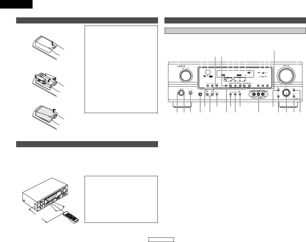
Inserting the batteries
qRemove the remote control unit’s rear cover.
wSet two R6P/AA batteries in the battery compartment in the indicated direction.
e Put the rear cover back on.
Notes on batteries:
•Replace the batteries with new ones if the set does not operate even when the remote control unit is operated nearby the unit. (The included batteries are only for verifying operation.)
•When inserting the batteries, be sure to do so in the proper direction, following the “<” and “>” marks in the battery compartment.
•To prevent damage or leakage of battery fluid:
•Do not use a new battery together with an old one.
•Do not use two different types of batteries.
•Do not short-circuit, disassemble, heat or dispose of batteries in flames.
•If the battery fluid should leak, carefully wipe the fluid off the inside of the battery compartment and insert new batteries.
•When replacing the batteries, have the new batteries ready and insert them as quickly as possible.
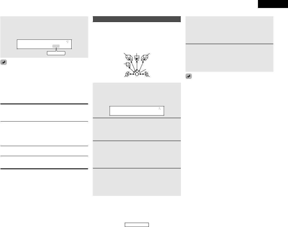
Operating range of the remote control unit
•Point the remote control unit at the remote sensor on the main unit as shown in the diagram.
•The remote control unit can be used from a straight distance of approximately 7 meters from the main unit, but this distance will be shorter if there are obstacles in the way or if the remote control unit is not pointed directly at the remote sensor.
•The remote control unit can be operated at a horizontal angle of up to 30 degrees with respect to the remote sensor.

 30° 30°


Approx. 7 m
NOTE:
•It may be difficult to operate the remote control unit if the remote sensor is exposed to direct sunlight or strong artificial light.
•Do not press buttons on the main unit and remote control unit simultaneously. Doing so may result in malfunction.
•Neon signs or other devices emitting pulsetype noise nearby may result in malfunction, so keep the set as far away from such devices as possible.
Getting Started
Part names and functions
Front panel
For details on the functions of these parts, refer to the pages given in parentheses ( ).
|
|
@5 |
|
|
|
|
@1 !9 |
|
|
|||||||||||||||
#1 |
#0@9@8@7@6 |
@4@3 |
@2 |
@0 |
!8 |
|||||||||||||||||||
|
|
|
|
|
|
|
|
|
|
|
|
|
|
|
|
|
|
|
|
|
|
|
|
|
|
|
|
|
|
|
|
|
|
|
|
|
|
|
|
|
|
|
|
|
|
|
|
|
|
|
|
|
|
|
|
|
|
|
|
|
|
|
|
|
|
|
|
|
|
|
|
|
|
|
|
|
|
|
|
|
|
|
|
|
|
|
|
|
|
|
|
|
|
|
|
|
|
|
|
|
|
|
|
|
|
|
|
|
|
|
|
|
|
|
|
|
|
|
|
|
|
|
|
|
|
|
|
|
|
|
|
|
|
|
|
|
|
|
|
|
|
|
|
|
|
|
|
|
|
|
|
|
|
|
|
|
|
|
|
|
|
|
|
|
|
|
|
|
|
|
|
|
|
|
|
|
|
|
|
|
|
|
|
|
|
|
|
|
|
|
|
|
|
|
|
|
|
|
|
|
|
|
|
|
|
|
|
|
|
|
|
|
|
|
|
|
|
|
|
|
|
|
|
|
t |
u |
o !1 |
|
!3 |
q w e r y |
|
i !0 |
!2 |
!4!5!6!7 |
q Power ON/STANDBY switch ················(7)
w Power indicator······································(7)
e Power switch ···································(7, 35) r Headphones jack (PHONES) ···············(18)
t ANALOG button···································(18)
y SPEAKER A/B buttons ··················(18, 35) u TONE DEFEAT button··························(27)
i Preset station select buttons ·······(28, 29) o STANDARD/NIGHT button ···········(19~23)
!05CH STEREO button ····························(24)
!1DIRECT/STEREO button······················(19)
!2V. AUX INPUT terminals ·······················(9)
!3SURROUND MODE button ···················(7)
!4SURROUND PARAMETER button ······(19)
!5SELECT knob······························(7, 20, 27)
!6TONE CONTROL button······················(27)
!7CH VOL button·····································(27)
!8MASTER VOLUME control knob ··········(7)
!9TUNING • (up)/ª (down) buttons ·····(28)
@0RT button··············································(30)
@1PTY button············································(30)
@2RDS button ···········································(30)
@3Master volume indicator·······················(7)
@4Display
@5INPUT mode indicator·························(19)
@6SIGNAL indicator ·································(19)
@7BAND button ········································(28)
@8EXT. IN button······································(17)
@9Remote control sensor··························(3)
#0INPUT MODE button ···························(18)
#1INPUT SELECTOR knob·························(7)
3
ENGLISH

ENGLISH
Getting Started
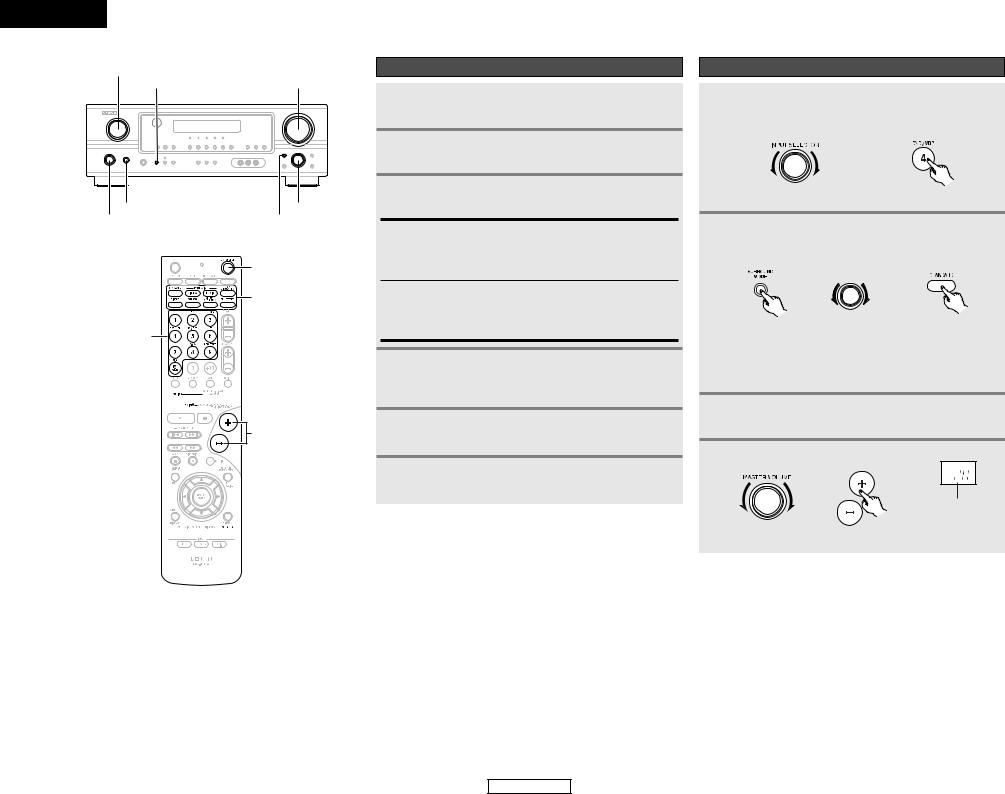
Remote control unit
on the functions of these parts, refer to the pages given in parentheses ( ).
Easy Operation
|
Remote control signal |
···············(32, 34) |
transmitter···················(3) |
|
Power buttons |
|
································(7, 33) |
Speaker system layout
2 Basic system layout
The following is an example of the basic layout for a system consisting of six speaker systems and a television monitor:
MODE
···················(7, 25)
source selector
···················(7, 32)
buttons
SETUP/SETUP
···················(11, 33)
buttons
33)
············(18, 23, 33)
TONE button
SELECT button |
mode selector
················(17~19)
MEMO
Tuner system/System buttons·················(28, 34)
Mode selector switches
································(7, 31)
Master volume control buttons·························(7)
MUTING button
····································(17)
SURROUND PARAMETER/System button···················(19, 33)
CH SELECT/ENTER button ·····················(20, 27)
RETURN button
····································(33)
SPEAKER button
································(7, 18)
DIMMER button
····································(18)
•The Dolby Surround Pro Logic II Cinema or Music mode can be chosen directly by pressing the CINEMA or MUSIC button on the remote control unit during playback in the Dolby Surround Pro Logic II mode.
•The DTS NEO:6 Cinema or Music mode can be chosen directly by pressing the CINEMA or MUSIC button on the remote control unit during playback in the DTS NEO:6 mode.
4
Subwoofer
Front speaker systems
Set these at the sides of the TV or screen with their front surfaces as flush with the front of the screen as possible.
Center speaker system
Surround speaker systems
ENGLISH
ENGLISH
Easy Operation
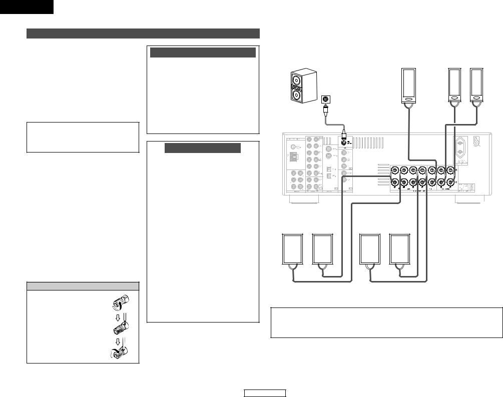
Speaker connections
•Connect the speaker terminals with the speakers making sure that like polarities are matched (< with <, > with >). Mismatching of polarities will result in weak central sound, unclear orientation of the various instruments, and the stereo image being impaired.
•When making connections, take care that none of the individual conductors of the speaker cable come in contact with adjacent terminals, with other speaker cable conductors, or with the rear panel.
NOTE:
NEVER touch the speaker terminals when the power is on. Doing so could result in electric shocks.
2 Speaker impedance
•When speaker systems A and B are used
separately, speakers with an impedance of 6 to 16 Ω/ohms can be connected for use as front speakers.
•Be careful when using two pairs of front speakers (A + B) at the same time, since
speakers with an impedance of 12 to 16 Ω/ohms in this case must be used.
•Speakers with an impedance of 6 to 16 Ω/ohms can be connected for use as center and surround speakers.
•The protector circuit may be activated if the unit is operated for long periods of time at high volumes when speakers with an impedance lower than the specified impedance are connected.
Connecting the speaker cables
1. Loosen by turning counterclockwise.
2. Insert the cable.
3. Tighten by turning clockwise.
Note on speaker impedance
The protector circuit may be activated if the unit is operated for long periods of time at high volumes when speakers with an impedance lower than the specified impedance (for example speakers with an impedance of less than 4 Ω/ohms) are connected. If the protector circuit is activated, the speaker output is cut off. Turn off the unit’s power, wait for the unit to cool down, improve the ventilation around the unit, then turn the power back on.
Protector circuit
This unit is equipped with a high-speed protection circuit. The purpose of this circuit is to protect the speakers under circumstances such as when the output of the power amplifier is inadvertently short-circuited and a large current flows, when the temperature surrounding the unit becomes unusually high, or when the unit is used at high output over a long period which results in an extreme temperature rise.
When the protection circuit is activated, the speaker output is cut off and the power supply indicator flashes. Should this occur, please follow these steps: be sure to switch off the power of this unit, check whether there are any faults with the wiring of the speaker cables or input cables, and wait for the unit to cool down if it is very hot. Improve the ventilation condition around the unit and switch the power back on.
If the protection circuit is activated again even though there are no problems with the wiring or the ventilation around the unit, switch off the power and contact a DENON service center.
Easy Operation
2 Connections
When making connections, also refer to the operating instructions of the other components.
Subwoofer |
|
Center |
|
Surround speaker |
|
speaker |
|
systems |
|
|
|
|
||
|
|
|
|
|
Connection terminal for a subwoofer with built-in amplifier.
|
|
(L) |
|
(R) |
IN |
|
|
|
|
> |
< |
> |
< > |
< |
|
|
|
(L) |
(R) |
(L) |
(R) |
< > |
> < |
< > |
> < |
Front speaker |
|
Front speaker |
systems (B) |
|
systems (A) |
|
|
|
Precautions when connecting speakers:
If a speaker is placed near a TV or video monitor, the colors on the screen may be disturbed by the speaker’s magnetism. If this should happen, move the speaker away to a position where it does not cause this effect.
5
ENGLISH
Easy Operation
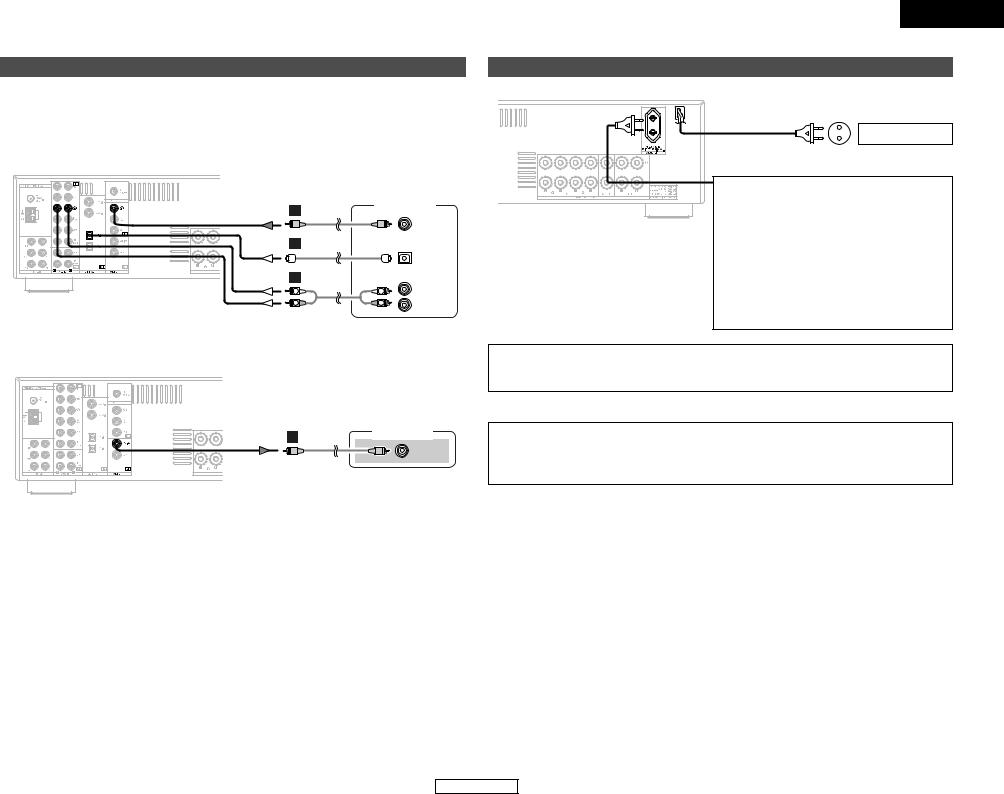
Connecting a DVD player and monitor TV
•To connect the digital audio output from the DVD player, you can choose from either the coaxial or optical connections. If you choose to use the coaxial connection, it needs to be assigned. For more information about Digital Input Assignment (  page 15).
•Connect a non-DVD video disc player (such as a laser disc, VCD/SVCD, or future high definition disc player) to the DVD/VDP terminals in the same way.
DVD player
F
VIDEO
OUT
D
OPTICAL
OUT
A |
|
AUDIO OUT |
|
|
|
L |
L |
L |
R |
R |
R |

 Audio signal flow is shown with white arrows; video signal flow is shown with gray arrows.
Monitor TV
F
VIDEO
IN
ENGLISH
Easy Operation
Connecting the power supply cord
AC outlet (Wall)
AC 230 V, 50 Hz
AC OUTLET
• SWITCHED (total capacity – 100 W (0.43 A)) The power to this outlet is turned on and off in conjunction with the POWER switch on the main unit, and when the power is switched between on and standby from the remote control unit.
No power is supplied from this outlet when this unit’s power is at standby. Never connect equipment whose total power consumption exceeds 100 W (0.43 A).
NOTE:
•Only use the AC OUTLET for connecting audio equipment. Never use it for hair driers, TVs or other electrical appliances.
CAUTION:
To completely disconnect this product from the mains, disconnect the plug from the wall socket outlet.
When setting up this product, make sure that the AC outlet you are using is easily acceptable.
6
ENGLISH
ENGLISH
Easy Operation
INPUT SELECTOR
SPEAKER A MASTER VOLUME
POWER |
SELECT |
ON/STANDBY |
SURROUND MODE |
|
ON/SOURCE |
|
SURROUND |
INPUT |
MODE |
|
|
SELECTOR |
|
MODE 1 

VOLUME


 SPEAKER
Turning on the power
1 Turn on your subwoofer.
2 Turn on your monitor (TV).
3 Press the POWER switch.
¢ ON:
The power turns on and the indicator lights.
Set the POWER switch to this position to turn the power on and off from the included remote control unit.
£ OFF:
The power turns off and the indicator is off.
In this position, the power cannot be turned on and off from the remote control unit.
4 Press the ON/STANDBY switch on the main unit or ON/SOURCE button on the remote control unit.
• Turn on the power.
5 Press the SPEAKER A button to turn the speakers on.
6 Set the MODE 1 switch to “AUDIO” (only when operating with the remote control unit).
Easy Operation
Playing the input source
1 Select the input source to be played.
Example: DVD
(Main unit) |
(Remote control unit) |
2 Select the play (surround) mode.
Example: STANDARD
|
SELECT |
(Main unit) |
(Remote control unit) |

 To select the surround mode while adjusting the surround parameters, tone defeat or tone control, press the SURROUND MODE button and then operate the selector.
3 Start playback on the selected component.
4 Adjust the volume.
|
The volume level is |
|
displayed on the |
|
master volume level |
(Main unit) |
(Remote control unit) display. |
7
ENGLISH
ENGLISH
Connecting Other Sources
Connecting Other Sources
Cable indications
The hookup diagrams on the subsequent pages assume the use of the following optional connection cables (not supplied).
|
|
Audio cable |
|
Video cable |
A |
Analog terminal (Stereo) |
|
F Video terminal |
|
|
(White) |
L |
L |
(Yellow) |
|
(Red) |
|
|
|
|
R |
R |
Video cable (75 Ω/ohm video pin-plug cable) |
|
|
|
Pin-plug cable |
|
|
|
|
|
|
|
B |
Analog terminal (Monaural, for subwoofer) |
|
||
|
|
Pin-plug cable |
|
|
C |
Digital terminal (Coaxial) |
|
|
|
|
(Orange) |
|
|
Signal direction |
|
Coaxial cable (75 Ω/ohm pin-plug cable) |
|
|
|
|
|
|
|||||||||||
|
|
|
|
|
|
|
|
|
|
|
|
|
|
|
|
|
|
|
D |
Digital terminal (Optical) |
|
|
|
|
|
|
|||||||||||
|
|
|
|
|
|
|
|
|
|
|
|
Audio signal |
|
|
|
|
|
|
|
Optical cable (Optical fiber cable) |
IN |
OUT |
OUT |
IN |
|||||||||||||
|
|
|
|
|
|
|
||||||||||||
|
|
|
|
|
|
|
|
|
|
|
|
Video signal |
|
|
|
|
|
|
E |
Speaker terminal |
|
|
|
|
|
||||||||||||
IN |
OUT |
OUT |
IN |
|||||||||||||||
|
|
|
|
|
|
|
|
|
|
|
|
|||||||
Speaker cable
NOTE:
•Do not plug in the power supply cord until all connections have been completed.
•When making connections, also refer to the operating instructions of the other components.
•Be sure to connect the left and right channels properly (left with left, right with right).
•Note that binding pin-plug cables together with power supply cords or placing them near a power transformer will result in hum or other noise.
8
ENGLISH

ENGLISH
Connecting Other Sources |
|
Connecting Other Sources |
|
|
|
Connecting a TV/DBS tuner |
|
Connecting a video camera or video game |
|
|
|
To connect the digital audio output from the TV or DBS tuner, you can choose from either the coaxial or optical connections. If you choose to use the coaxial connection, it needs to be assigned. For more information about Digital Input Assignment (  page 15).
F |
TV |
|
VIDEO
OUT
D
OPTICAL
OUT
A |
|
AUDIO OUT |
L |
L |
L |
R |
R |
R |
|
Video camera / |
|
|
Video game |
|
A |
|
AUDIO OUT |
L |
L |
L |
|
||
R |
R |
R |
F |
|
|
|
|
VIDEO |
|
|
OUT |
Connecting the external inputs (EXT. IN) terminals
•These terminals are for inputting multi-channel audio signals from an external decoder, or a component with a different type of multi-channel decoder, such as a DVD Audio player, a multichannel Super Audio CD player, or another future multi-channel sound format decoder.
•The video signal connection is the same as that for a DVD player.
•For instructions on playback using the external input (EXT. IN) terminals (  page 17).
|
DVD Audio-Video / |
||
|
Super Audio CD player / |
||
|
External decoder |
||
A |
5.1ch AUDIO OUT |
||
|
|
FRONT |
|
L |
L |
L |
|
R |
R |
R |
|
B |
|
|
|
|
|
CENTER |
|
A |
|
SURROUND |
|
L |
L |
||
L |
|||
R |
R |
R |
|
B |
|
SUB- |
|
|
|
||
|
|
WOOFER |
|
Connecting a CD player
To connect the digital audio output from the CD player, you can choose either coaxial or optical connection. If you choose to use the optical connection, it needs to be assigned. For more information about Digital Input Assignment (  page 15).
CD player
C
COAXIAL
OUT
A |
|
AUDIO OUT |
|
|
|
L |
L |
L |
|
||
R |
R |
R |
discs on which special copyright protection measures have been taken, the digital signals not be output from the DVD player. In this case, connect the DVD player’s analog multioutput to the AVR-1306’s EXT. IN terminals for playback. Also refer to your DVD player’s
instructions.
9
ENGLISH
Connecting Other Sources
Connecting a tape deck, CD recorder or MD recorder
|
Tape deck / |
|
|
CD recorder / |
|
|
MD recorder |
|
A |
|
AUDIO OUT |
|
|
|
L |
L |
L |
|
||
R |
R |
R |
A |
|
AUDIO IN |
|
|
|
L |
L |
L |
|
||
R |
R |
R |
noise is generated, move the tape deck further away from the source of such noise.
Connecting a VCR
If you wish to perform analog dubbing from a digital source, such as a DVD recorder to an analog recorder such as a cassette deck, you will need to connect the analog inputs and outputs as shown below, in addition to the digital audio connections.
F |
Video deck |
|
VIDEO
OUT
F
VIDEO
IN
A |
|
AUDIO IN |
|
|
|
L |
L |
L |
R |
R |
R |
A |
|
AUDIO OUT |
|
|
|
L |
L |
L |
|
||
R |
R |
R |
NOTE:
•When recording to a VCR, it is necessary that the type of cable used with the playback source
equipment be the same type that is connected to the AVR-1306 VCR OUTPUT terminal. Example: VCR IN → Video cable : VCR OUT → Video cable
ENGLISH
Connecting Other Sources
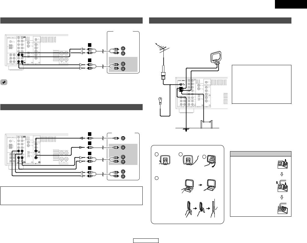
Connecting the antenna terminals
An FM antenna cable plug can be connected directly to the unit.
Direction of broadcasting |
|
station |
AM loop |
|
|
FM antenna |
antenna |
(Supplied) |
75 Ω/ohm COAXIAL cable
FM indoor antenna (Supplied)
NOTE:
•Do not connect two FM antennas simultaneously.
•Even if an external AM antenna is used, do not disconnect the AM loop antenna.
•Make sure the AM loop antenna lead terminals do not touch metal parts of the panel.
Ground |
AM outdoor antenna |
2 AM loop antenna assembly
1 |
2 |
 Remove the vinyl tie and take out the connection line.
4
a. Antenna placed on a stable surface.
Mount
b. Hanging the antenna on a wall.
Connect to the AM antenna terminals.
3
Bend in the reverse direction.
Use the
installation hole to secure the antenna to a wall, etc.
Connection of AM antennas
1. Push the lever.
2. Insert the conductor.
3. Return the lever.
10
ENGLISH
ENGLISH
System Setup
Use System Setup to customize a variety of settings to suit your listening environment. For the contents of a system menu and the initial setting of this unit (  page 16).
System Setup
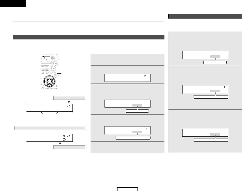
Setting the Speaker Configuration
The composition of the signals output to each channel and the frequency response are adjusted automatically according to the combination of speakers actually being used.
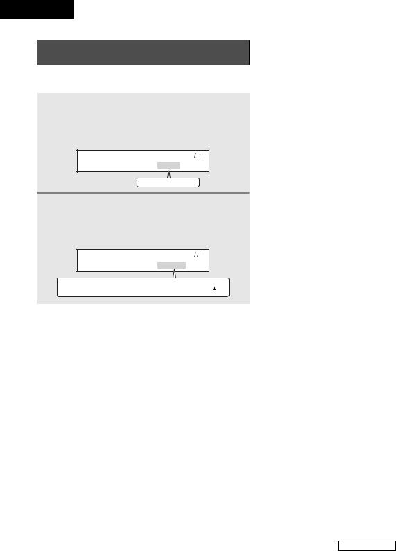
Front display
•You can change the settings using the buttons on the remote control unit.
•The AVR-1306 is equipped with an alpha numeric front panel display that can also be used to check and adjust settings. Some representative front display examples are shown below.
MODE 1 
ENTER
SETUP 

 CURSOR
No.
[ Display ]
*COAX1 CD
|
|
|
|
|
Currently selected line |
|
|
Current setting |
|
|
|
|
|
|
Press the CURSOR F button to execute.
*TEST TONE Yes<
Currently selected line
1 Set the MODE 1 switch to “AUDIO”.
2 Press the SETUP button to enter the setting.
*System Setup
3 Press the ENTER or CURSOR H button to select the setting, then press the CURSOR F or G button to select the parameter.
*Front Large
Large
 Small
Small
4 Press the ENTER or CURSOR H button to confirm the new settings.
*Center Small
Large
 Small
Small
 None
None
5 Press the SETUP button to finish system set up.
11
1 Press the CURSOR F or G button to select your front speaker type, then press the ENTER or CURSOR H button to switch to the center speaker setting.
*Front Large
Large
 Small
Small
2 Press the CURSOR F or G button to select your center speaker type, then press the ENTER or CURSOR H button to switch to the surround speaker setting.
*Center Small
Large
 Small
Small
 None
None

 When “Small” has been selected for the front speakers, “Large” cannot be selected for the center speaker.
3 Press the CURSOR F or G button to select your surround speaker type, then press the ENTER or CURSOR H button to switch to the subwoofer setting.
*Surr . Small
Large
 Small
Small
 None
None

 When “Small” has been selected for the front speakers, “Large” cannot be selected for the surround speakers.
ENGLISH
System Setup
4 Press the CURSOR F or G button to select your subwoofer setting, then press the ENTER or CURSOR H button to enter the settings and switch to the Delay Time setting.
*Subwoofer Yes
Yes
 No
No
“Large” or “Small” not according to the actual size of speaker but according to the speaker’s capacity for playing frequency (bass sound below the frequency set for the Frequency) signals. If you are unsure, try comparing sound at both settings (setting the volume to a level low so as not to damage the speakers) to determine the
setting.
2 Parameters
Large:
Select this when using speakers that have sufficient ability to reproduce bass sound below the frequency set for the crossover frequency mode.
Small:
Select this when using speakers that do not have sufficient ability to reproduce bass sound below the frequency set for the crossover frequency mode. When this is set, bass sound with a frequency below the frequency set for the crossover frequency mode is sent to the subwoofer.
None:
Select this when no speakers are installed.
Yes / No:
Select “Yes” when a subwoofer is installed, “No” when a subwoofer is not installed.

 If the subwoofer has sufficient low frequency playback capacity, good sound can be achieved even when “Small” is set for the front, center and surround speakers.
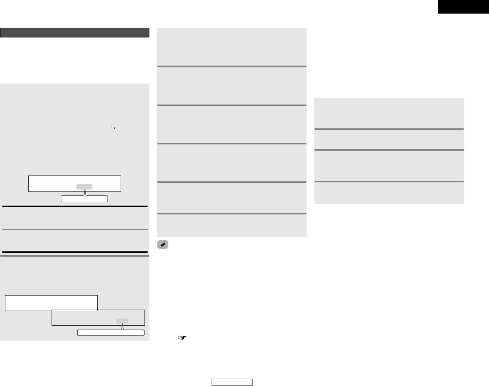
Setting the Delay Time
Input the distance between the listening position and each speaker to set the delay time for the surround playback.
Preparations:
Measure the distances between the listening position and the speakers.
FL Center FR
Subwoofer
Listening position
SL |
SR |
1 Press the CURSOR F or G button to set the distance from the front L speaker to the listening position, then press the ENTER or CURSOR H button to switch to the front R speaker setting.
*Front L 3 . 6m
2 Press the CURSOR F or G button to set the distance from the front R speaker to the listening position, then press the ENTER or CURSOR H button to switch to the center speaker setting.
3 Press the CURSOR F or G button to set the distance from the center speaker to the listening position, then press the ENTER or CURSOR H button to switch to the surround L speakers setting.
4 Press the CURSOR F or G button to set the distance from the surround L speakers to the listening position, then press the ENTER or CURSOR H button to switch to the surround R speaker setting.
ENGLISH
System Setup
5 Press the CURSOR F or G button to set the distance from the surround R speakers to the listening position, then press the ENTER or CURSOR H button to switch to the subwoofer setting.
6 Press the CURSOR F or G button to set the distance from the subwoofer to the listening position, then press the ENTER or CURSOR H button to enter the setting and switch to the Subwoofer Mode setting.
number changes in units of 0.1 meters each time one of buttons is pressed. Select the value closest to the
distance.
difference in distance for the various speaker settings not be greater than 6.0 meters.
12
ENGLISH
ENGLISH
System Setup
Setting the Subwoofer Mode and
Crossover Frequency
Set the subwoofer mode and crossover frequency mode according to the speaker system being used.
1 Press the CURSOR F or G button to select the subwoofer mode, then press the ENTER or CURSOR H button to enter the setting and switch to the crossover frequency setting.
*SW Mode Norm
Norm
 +Main
+Main
2 Press the CURSOR F or G button to select the crossover frequency, then press the ENTER or CURSOR H button to enter the setting and switch to the Test Tone setting.
*Cr . Over 180Hz
60Hz
 80Hz
80Hz
 100Hz
100Hz
 120Hz
120Hz
 135Hz 200Hz
 180Hz
180Hz
 150Hz
150Hz
2 Assignment of low frequency signal range
The signals produced from the subwoofer channel are LFE signals (during playback of Dolby Digital or DTS signals) and the low frequency signal range of channels set to “SMALL” in the setup. The low frequency signal range of channels set to “LARGE” are produced from those channels.
2 Crossover Frequency
•When “Subwoofer” is set to “Yes” at the “Speaker Configuration” setting, set the frequency (Hz) below which the bass sound of the various speakers is to be output from the subwoofer (the crossover frequency).
•For speakers set to “Small”, sound with a frequency below the crossover frequency is cut, and the cut bass sound is output from the subwoofer instead.
(• When “Subwoofer” is set to “No”, the bass sound is output from the speakers set as “Large”.)
2 Subwoofer Mode
•The subwoofer mode setting is only valid when “Large” is set for the front speakers and “Yes” is set for the subwoofer in “Setting the Speaker Configuration” (  page 11, 12).
•When the “LFE+MAIN” playback mode is selected, the low frequency signal range of channels set to “Large” is produced simultaneously from those channels and the subwoofer channel.
In this playback mode, the low frequency range expands more uniformly through the room, but depending on the size and shape of the room, interference may result in a decrease of the actual volume of the low frequency range.
•Selection of the “LFE” play mode will play the low frequency signal range of the channel selected with “Large” from that channel only. Therefore, the low frequency signal range that is played from the subwoofer channel is only the low frequency signal range of LFE (only during Dolby Digital or DTS signal playback) and the channels specified as “Small” in the setup menu.
•Select the play mode that offers the fullest bass.
•When the subwoofer is set to “Yes”, bass sound is output from the subwoofer regardless of the subwoofer mode setting in surround modes other than Dolby/DTS.
•In surround modes other than Dolby Digital and DTS, if the subwoofer is set to “Yes”, the low frequency portion is always output to the subwoofer channel. For details, refer to “Surround modes and parameters” (  page 40).
13
System Setup
ENGLISH
System Setup
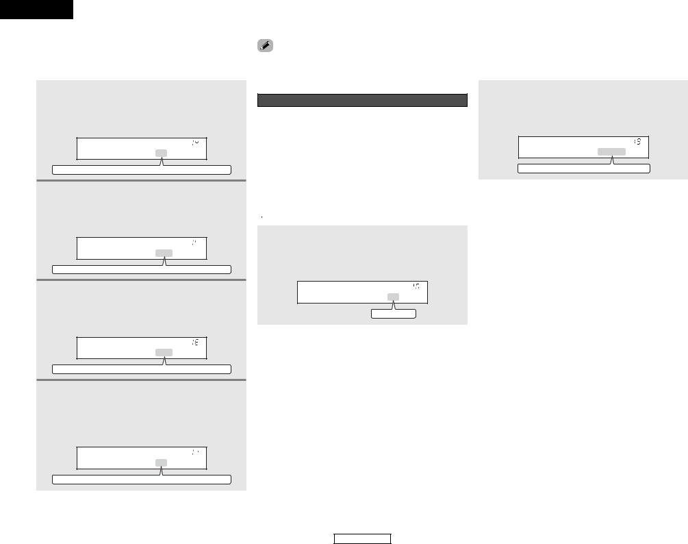
Setting the Test Tone
•Use this setting to adjust to that the playback level between the different channel is equal.
•From the listening position, listen to the test tones produced from the speakers to adjust the level.
•The level can also be adjusted directly from the remote control unit.
1 |
• Press the CURSOR F button to switch the test |
||
tone mode. |
|||
|
• Press the ENTER or CURSOR H button to |
||
|
switch to the digital input (COAXIAL) setting. |
||
|
|
|
|
|
|
*TEST TONE Yes< |
|
|
|
|
|
|
|
|
|
|
Press the CURSOR F or G button to select the |
||
2 test tone mode, then press the CURSOR H |
|||
button to start test tone.
T . TONE Auto >
Auto
 Manual
Auto:
Adjust the level while listening to the test tones produced automatically from the different speakers.
Manual:
Select the speaker from which you want to produce the test tone to adjust the level.
3 Press the CURSOR F or G button to set the front L channel level, then press the CURSOR H button to switch to the center channel level (manual mode).
AUTO - FL
FL VOL |
0dB |
|
|
-12dB
 0dB
0dB
 +12dB
+12dB
4 Press the CURSOR F or G button to set the center channel level, then press the CURSOR H button to switch to the front R channel level (manual mode).
5 Press the CURSOR F or G button to set the front R channel level, then press the CURSOR H button to switch to the surround R channel level (manual mode).
6 Press the CURSOR F or G button to set the surround R channel level, then press the CURSOR H button to switch to the surround L channel level (manual mode).
7 Press the CURSOR F or G button to set the surround L channel level, then press the CURSOR H button to switch to the subwoofer channel level (manual mode).
8 Press the CURSOR F or G button to set the subwoofer channel level, then press the ENTER button to finish the test tone.
9 Press the ENTER or CURSOR H button to switch the Digital In Assignment (COAXIAL) setting.
ENGLISH
System Setup
2 Adjusting the test tone
•Before playing with the surround function, be sure to use the test tones to adjust the playback level from the different speakers. This adjustment can be performed with the system setup or from the remote control unit, as described below.
•Adjusting with the remote control unit using the test tones is only possible in the “Auto” mode and only effective in the STANDARD (DOLBY/DTS SURROUND) modes. The adjusted levels for the different modes are automatically stored in the memory.
1 Press the STANDARD button to select the STANDARD (DOLBY/DTS SURROUND) modes.
2 Press the TEST TONE button.
• Test tones are output from the different speakers.
3 Press the CURSOR F or G button to adjust so that the volume of the test tones is the same for all the speakers.
4 After completing the adjustment, press the TEST TONE button again.
adjusting the level of an active subwoofer system, you also need to adjust the subwoofer’s own volume control. you adjust the channel levels while in the system setup level mode, the channel level adjustments made will all surround modes. Consider this mode a master
level adjustment mode.
you have completed the system setup channel level you can then activate the individual surround and adjust channel levels that will be remembered for
of those modes. Then, whenever you activate a particular sound mode, your preferred channel level for just that mode will be recalled. Check the for adjusting channel levels within each surround
( 
 page 27).
14
ENGLISH
ENGLISH
System Setup System Setup
Setting the Digital In Assignment |
|
Setting the Ext. In Subwoofer Level |
|
This setting assigns the digital input terminals of the AVR-1306 |
“OFF” if nothing is connected. |
Set the method of playback of the analog input signal connected |
|
and “V. AUX” cannot be selected. |
|||
for the different input sources. |
to the EXT. IN terminal. |
||
|
1 Press the CURSOR F or G button to assign the input function connected to the COAXIAL 1 input terminal, then press the ENTER or CURSOR H button to switch the COAXIAL 2 input setting.
*COAX1 CD
CD
 AUX
AUX
 DVD
DVD
 TV
TV
 VCR
VCR
 CDR
CDR
 OFF
OFF
2 Press the CURSOR F or G button to assign the input function connected to the COAXIAL 2 input terminal, then press the ENTER or CURSOR H button to switch the OPTICAL 1 input setting.
*COAX2 AUX
CD
 AUX
AUX
 DVD
DVD
 TV
TV
 VCR
VCR
 CDR
CDR
 OFF
OFF
3 Press the CURSOR F or G button to assign the input function connected to the OPTICAL 1 input terminal, then press the ENTER or CURSOR H button to switch the OPTICAL 2 input setting.
*OPT1 DVD
CD
 AUX
AUX
 DVD
DVD
 TV
TV
 VCR
VCR
 CDR
CDR
 OFF
OFF
4 Press the CURSOR F or G button to assign the input function connected to the OPTICAL 2 input terminal, then press the ENTER or CURSOR H button to switch the Auto Surround Mode setting.
*OPT2 TV
CD
 AUX
AUX
 DVD
DVD
 TV
TV
 VCR
VCR
 CDR
CDR
 OFF
OFF
Setting the Auto Surround Mode
The surround mode used last for the three types of input signals shown below is stored in the memory, and the signal is automatically played with that surround mode the next time it is input.
Note that the surround mode setting is also stored separately for the different input sources.
q Analog and PCM 2-channel signals (STEREO)
w2-channel signals in the Dolby Digital, DTS or another multichannel format (DOLBY PLII Cinema)
eMulti-channel signals in the Dolby Digital, DTS or another multichannel format (DOLBY/DTS SURROUND)

 Default settings are indicated in ( ).
Press the CURSOR F or G button to select the Auto
Surround mode, then press the ENTER or CURSOR H button to switch the Ext. In Subwoofer Level setting.
*Auto Surr . ON
ON
 OFF
OFF
Press the CURSOR F or G button to select the ext. in subwoofer channel level playback, then press the ENTER or CURSOR H button if you want to start the settings over from the beginning.
*Ext . In SW+15dB
+0dB
 +5dB
+5dB
 +10dB
+10dB
 +15dB
+15dB
15
ENGLISH

|
|
|
|
|
|
|
|
|
|
|
ENGLISH |
System Setup |
|
|
|
|
|
|
|
|
System Setup |
||
|
|
|
|
|
|
|
|
|
|
|
|
System setup items and default values (set upon shipment from the factory) |
|
|
|
|
|
||||||
|
|
|
|
|
|
|
|
|
|
|
|
|
|
System Setup |
|
|
Default settings |
|
Page |
|
|
||
|
|
Input the combination of speakers in your system and their |
Front Sp. |
Center Sp. |
|
Subwoofer |
Surround Sp. |
|
|
|
|
|
Speaker |
corresponding sizes (SMALL for regular speakers, LARGE |
|
|
|
|
|||||
|
|
|
|
|
|
11, 12 |
|
|
|||
1 |
for full-size, full-range) to automatically set the composition |
|
|
|
|
|
|
|
|||
Configuration |
|
|
|
|
|
|
|
||||
|
of the signals output from the speakers and the frequency |
Large |
Small |
|
Yes |
Small |
|
|
|
||
|
|
|
|
|
|
||||||
|
|
response. |
|
|
|
|
|
||||
|
|
|
|
|
|
|
|
|
|
|
|
|
|
|
|
|
|
|
|
|
|
|
|
|
|
This parameter is for optimizing the timing with which the |
Front |
Center |
|
Subwoofer |
Surround |
|
|
|
|
2 |
Delay Time |
audio signals are produced from the speakers and |
L & R |
|
L & R |
12 |
|
|
|||
|
|
|
|
|
|||||||
|
|
subwoofer according to the listening position. |
|
3.6 m |
3.6 m |
|
3.6 m |
3.0 m |
|
|
|
|
|
|
|
|
|
|
|
|
|
|
|
3 |
Subwoofer |
This selects the subwoofer speaker for playing deep bass |
|
Subwoofer mode = Normal |
|
13 |
|
|
|||
|
Mode |
signals. |
|
|
|
|
|
|
|
|
|
4 |
Crossover |
Sets the frequency (Hz) below which the bass sound of |
|
180 Hz |
|
|
13 |
|
|
||
|
Frequency |
the various speakers is to be output from the subwoofer. |
|
|
|
|
|
|
|
|
|
|
|
This adjusts the volume of the signals output from the |
Front |
Center |
|
Subwoofer |
Surround |
|
|
|
|
5 |
Test Tone |
speakers and subwoofer for the different channels in order |
L & R |
|
L & R |
14 |
|
|
|||
|
|
|
|
|
|||||||
|
|
to obtain optimum effects. |
|
0 dB |
0 dB |
|
0 dB |
0 dB |
|
|
|
|
|
|
|
|
|
|
|
|
|
|
|
|
|
|
Input |
CD |
AUX |
|
DVD / VDP |
TV / DBS |
|
|
|
|
Digital In |
This assigns the digital input terminals for the |
source |
|
|
|
|
||||
6 |
|
|
|
|
|
15 |
|
|
|||
Assignment |
different input sources. |
Digital |
COAXIAL1 |
COAXIAL2 |
|
OPTICAL1 |
OPTICAL2 |
|
|
||
|
|
|
|
|
|||||||
|
|
|
Inputs |
|
|
|
|
||||
|
|
|
|
|
|
|
|
|
|
|
|
|
|
|
|
|
|
|
|
|
|
|
|
|
Auto |
Auto surround mode function setting. |
|
|
Auto Surround Mode = ON |
|
15 |
|
|
||
7 |
Surround |
|
|
|
|
|
|||||
|
Mode |
|
|
|
|
|
|
|
|
|
|
|
|
|
|
|
|
|
|
|
|||
8 |
Ext. In SW |
Sets the Ext. In Subwoofer channel playback level. |
|
Ext. In SW Level = +15 dB |
|
15 |
|
|
|||
|
Level |
|
|
|
|
|
|
|
|
|
|
16
ENGLISH
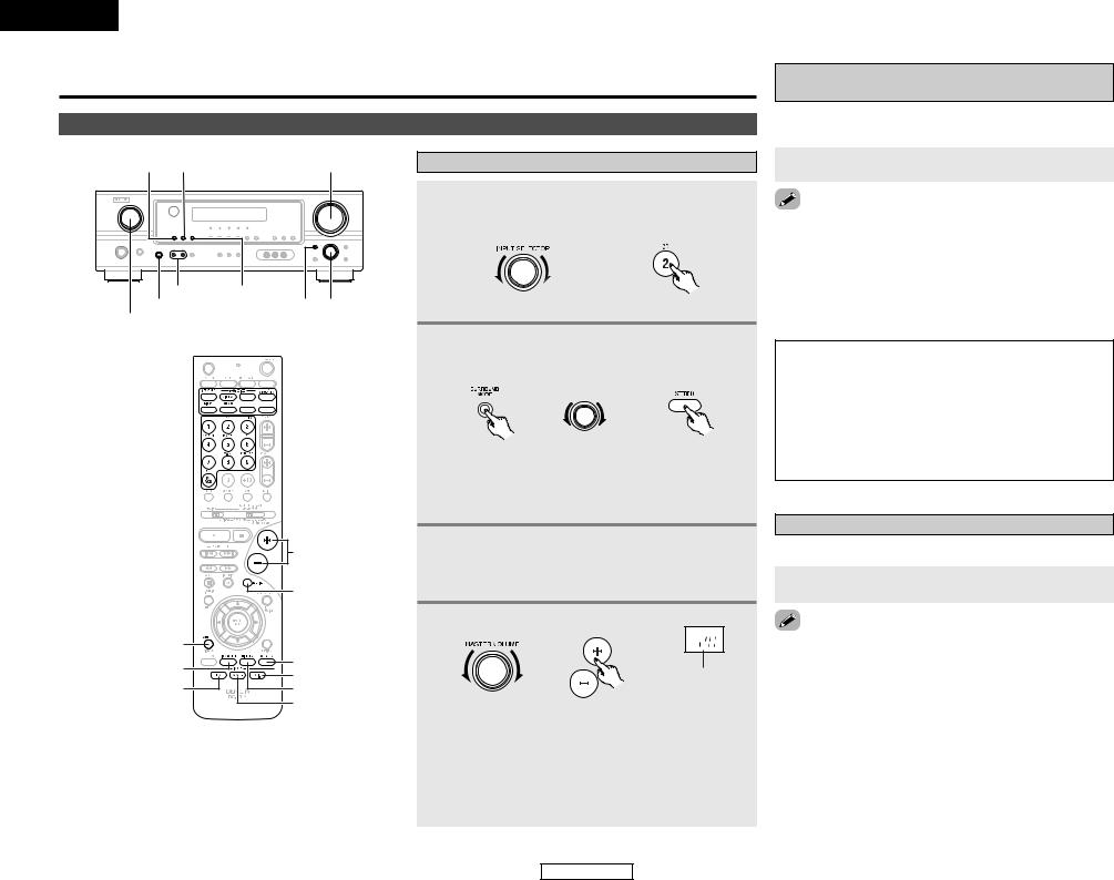
ENGLISH
Basic Operation
Playback
INPUT MODE ANALOG |
MASTER VOLUME |
SPEAKER EXT. IN
PHONES SURROUND MODE SELECT INPUT SELECTOR


 SURROUND
MODE
INPUT SELECTOR 
|
VOLUME |
|
|
MUTING |
|
STATUS |
|
|
VIDEO SELECT |
SPEAKER |
|
EXT. IN |
||
INPUT MODE |
||
DIMMER |
||
|
ANALOG |
Playing the input source
1 Select the input source to be played.
Example: CD
(Main unit) |
(Remote control unit) |
2 Select the play (surround) mode.
Example: STEREO
|
SELECT |
(Main unit) |
(Remote control unit) |

 To select the surround mode while adjusting the surround parameters, tone defeat or tone control, press the SURROUND MODE button and then operate the selector.
3 Start playback on the selected component.

 For operating instructions, refer to the component’s manual.
4 Adjust the volume.
|
The volume level is |
|
displayed on the |
|
master volume level |
(Main unit) |
(Remote control unit) display. |

 The volume can be adjusted within the range of –70 to 0 to 18 dB, in steps of 1 dB. However, when the channel level is set as described (
  page 27), if the volume for any channel is set at +1 dB or greater, the volume cannot be adjusted up to 18 dB. (In this case the maximum volume is adjusted to “18 dB — (Maximum value of channel level)”.)
17
Basic Operation
Playback using the external input (EXT. IN) terminals
The signals being input to the external decoder input terminals are played without passing through the surround circuitry.
Press the EXT. IN button to select the external input.
the external input mode:
the INPUT MODE or ANALOG button to switch to the input mode (  page 18, 19).
external input mode can be set for any input source. To video while listening to sound, select the input source to the video signal is connected, then set this mode. subwoofer output level is too high, set the “SW ATT.”
parameter to “ON”.
NOTE:
•When the input mode is set to the external input (EXT. IN), the play mode (DIRECT, VIRTUAL SURROUND, STEREO, STANDARD (DOLBY/DTS SURROUND), 5CH STEREO or DSP SIMULATION) cannot be selected.
•In play modes other than the external input mode, the signals connected to the EXT. IN terminals cannot be reproduced. In addition, signals cannot be output from channels not connected to the input terminals.
Turning the sound off temporarily (MUTING)
Use this to turn off the audio output temporarily.
Press the MUTING button.
the MUTING mode:
the MUTING button again.
the VOLUME button on the remote control unit, or the volume up or down via the front panel MASTER
knob.
ENGLISH
Basic Operation
Listening over headphones
Connect the headphones to the PHONES jack.
•The speaker output is automatically turned off when headphones are connected.
NOTE:
•To prevent hearing loss, do not raise the volume level excessively when using headphones.
Combining the currently playing sound with the desired image (VIDEO SELECT)
Press the VIDEO SELECT button repeatedly until the desired source appears on the display.
IN=V SOURCE

 Use this switch to monitor a video source other than the audio source.
simulcast playback:
“SOURCE” by pressing the VIDEO SELECT button. the program source to the component connected to
video input terminals.
Selecting the front speakers
Press the SPEAKER A or B button to turn the corresponding speaker pair on.

 The front speaker A, B setting can be also be changed with the SPEAKER button on the remote control unit.
Checking the currently playing program source
2 Front panel display
Press the STATUS button.

 Descriptions of the unit’s operations are also displayed on the front panel display. In addition, the display can be switched to check the unit’s operating status while playing a source.
2 Using the dimmer function
Press the DIMMER button.

 The display brightness changes in four steps (bright, medium, dim and off).
Input mode
The AVR-1306 has an AUTO signal detection mode that automatically identifies the type of incoming audio signals, but is also equipped with a manual mode that can be switched according to the type of input audio signals.
2 Selecting the AUTO, PCM and DTS modes
Press the INPUT MODE button.

 The mode switches as shown below each time the INPUT MODE button is pressed:
AUTO  PCM
PCM  DTS
DTS
ENGLISH
Basic Operation
AUTO (auto mode):
In this mode, the types of signals being input to the digital and analog input terminals for the selected input source are detected and the program in the AVR-1306’s surround decoder is selected automatically upon playback. This mode can be selected for all input sources other than TUNER.
The presence or absence of digital signals is detected, the signals input to the digital input terminals are identified and decoding and playback are performed automatically with the DTS, Dolby Digital or PCM (2 channel stereo) format. If no digital signal is being input, the analog input terminals are selected.
Use this mode to play Dolby Digital signals.
PCM (exclusive PCM signal playback mode):
Decoding and playback are only performed when PCM signals are being input.
Note that noise may be generated when using this mode to play signals other than PCM signals.
DTS (exclusive DTS signal playback mode):
Decoding and playback are only performed when DTS signals are being input.
2 Selecting the analog mode
Press the ANALOG button to switch to the analog input.
ANALOG (exclusive analog audio signal playback mode):
The signals input to the analog input terminals are decoded and played.
NOTE:
•Input mode when playing DTS sources:
Noise will be output if DTS-compatible CDs or LDs are played in the “ANALOG” or “PCM” mode.
When playing DTS-compatible sources, be sure to connect the source component to the digital input terminals (OPTICAL/COAXIAL) and set the input mode to “DTS”.
18
ENGLISH
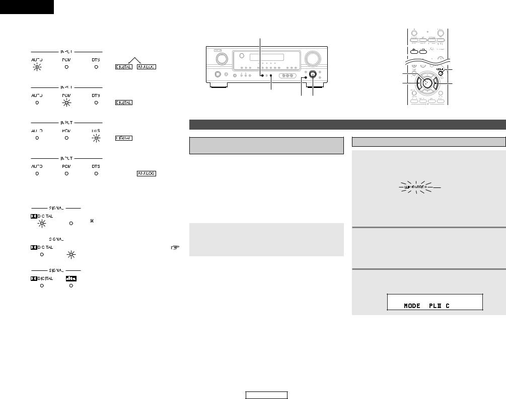
ENGLISH
Basic Operation
2 Input mode display |
STANDARD |
|
|
• In the AUTO mode |
|
Depending on the input signal.
• In the DIGITAL PCM mode
•In the DIGITAL DTS mode
•In the ANALOG mode
DIRECT/STEREO
SURROUND PARAMETER SELECT
Surround
Playing audio sources (CDs and DVDs) 2-channel playback modes
•The AVR-1306 is equipped with 2-channel playback modes exclusively for music.
•Select the mode to suit your tastes.
2 Input signal display
• DOLBY DIGITAL
|
|
|
|
|
|
|
|
|
The |
“DIGITAL” indicator lights |
|
|
|
|
|
|
|
|
|
||
• DTS |
|
|
when digital signals are being input |
|||||||
|
|
properly. If the “DIGITAL” indicator |
||||||||
|
|
|
|
|
|
|
|
|
||
|
|
|
|
|
|
|
|
|
does not light, check whether the |
|
|
|
|
|
|
|
|
|
|
Digital In Assignment setup ( |
|
|
|
|
|
|
|
|
|
|||
|
|
|
|
|
|
|
|
|
page 15) and connections are correct |
|
• PCM |
|
|
and |
whether the component’s |
||||||
|
|
|
|
|||||||
power is turned on.
2 DIRECT mode
Use this mode to achieve good quality 2-channel sound while watching images. In this mode, the audio signals bypass such circuits as the tone circuit and are transmitted directly, resulting in good quality sound.
Press the DIRECT/STEREO button on the main unit or the DIRECT button on the remote control unit to select the DIRECT mode.
2 STEREO mode
Use this mode to adjust the tone and achieve the desired sound while watching images.
|
|
Press the DIRECT/STEREO button on the main unit |
|
NOTE: |
|||
|
or the STEREO button on the remote control unit to |
||
• The “DIGITAL” indicator will light when playing CD-ROMs |
|
||
containing data other than audio signals, but no sound will |
|
select the STEREO mode. |
|
be heard. |
|
|
|
|
|
||
|
|
|
19
Basic Operation
STANDARD 

DIRECT 


 STEREO
ENTER |
SURROUND |
|
PARAMETER |
||
CURSOR F |
||
CURSOR G |
Dolby Pro Logic II mode
1 Press the STANDARD button to select the Dolby Pro Logic II mode.
• The Dolby Pro Logic II indicator lights.
Lights

 The mode switches as shown below each time the button is pressed.
DOLBY PLII 
 DTS NEO:6
2 Play a program source.

 For operating instructions, refer to the manuals of the respective components.
3 Press the SURROUND PARAMETER button to select the surround parameter mode.
ENGLISH
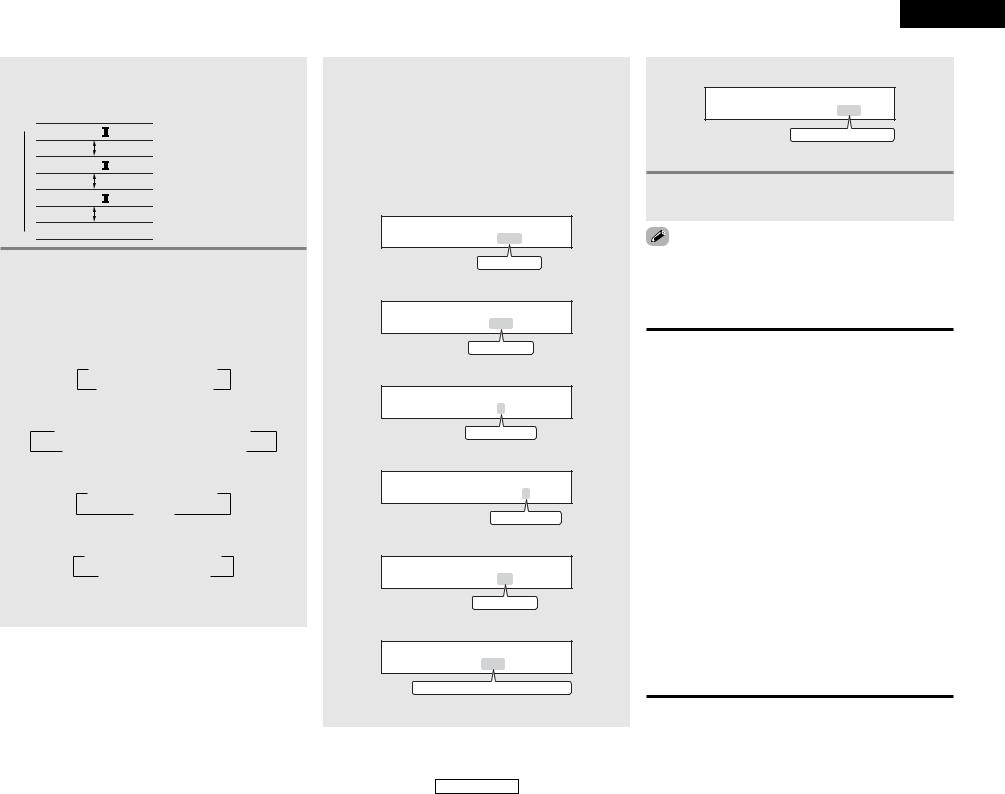
Basic Operation
4 Turn the SELECT knob, and press the CURSOR F or G button to select the optimum mode for the source.


 (Pro Logic II Cinema mode)


 (Pro Logic II Music mode)


 (Pro Logic II Game mode)


 (Dolby Pro Logic mode)
5 Press the SURROUND PARAMETER button to select the various parameters.

 The mode switches as shown below each time the button is pressed.
• When the Cinema mode:
 MODE CINEMA
  CINEMA EQ
DEFAULT TONE DEFEAT
• When the Music mode:
 MODE MUSIC
  TONE DEFEAT
  PANORAMA
DEFAULT CENTER WIDTH
  DIMENSION
• When the Game mode:
 MODE GAME
  TONE DEFEAT
DEFAULT
• When the Dolby Pro Logic mode:
 MODE DOLBY PL
  CINEMA EQ
DEFAULT TONE DEFEAT

 If you do want the bass and treble to be adjusted, turn off the tone defeat mode.
6 Turn the SELECT knob, and press the CURSOR F or G button to set the various surround parameters.

 When the surround parameters are set using the buttons on the main unit, stop operating the buttons after completing the settings. The settings are automatically finalized and the normal display reappears after several seconds.
• Cinema EQ setting:
CINEMA EQ OFF
ON
 OFF
OFF
• PANORAMA setting
PANORAMA OFF
ON
 OFF
OFF
• DIMENSION setting
DIMENSION 3
0
 3
3
 6
6
• CENTER WIDTH setting
CENTER WIDTH 3
0
 4
4
 7
7
• TONE DEFEAT setting
TONE DEF . ON
ON
 OFF
OFF
• D. COMP. setting
D . COMP . OFF
OFF
 LOW
LOW
 MID
MID
 HIGH
HIGH

 This parameter is displayed during DOLBY DIGITAL playback.
ENGLISH
Basic Operation
• DEFAULT setting
DEFAULT Y/N
YES
 Y/N
Y/N
 NO
NO

 Select “YES” to reset to the factory defaults.
7 Press the ENTER button to finish the surround parameter mode.
making parameter settings, the display will return to the condition several seconds after the last button was and the setting will be completed.
2 Surround parameters q
Pro Logic II Mode:
The Cinema mode is for use with stereo television shows and all programs encoded in Dolby Surround.
The Music mode is recommended for stereo music and surround-encoded stereo music sources.
The Pro Logic mode offers the same robust surround processing as original Pro Logic in case the source content is not of optimum quality.
The Game mode is for playing games. The game mode can only be used with 2-channel audio sources.
Select one of the modes (“Cinema”, “Music”, “Pro Logic” or “Game”).
•Panorama Control:
This mode extends the front stereo image to include the surround speakers for an exciting “wraparound” effect with side wall imaging.
Select “OFF” or “ON”.
•Dimension Control:
This control gradually adjusts the soundfield either towards the front or towards the rear.
The control can be set in 7 steps from 0 to 6.
•Center Width Control:
This control adjusts the center image so it may be heard only from the center speaker; only from the left/right speakers as a phantom image; or from all three front speakers to varying degrees.
The control can be set in 8 steps from 0 to 7.
20
ENGLISH
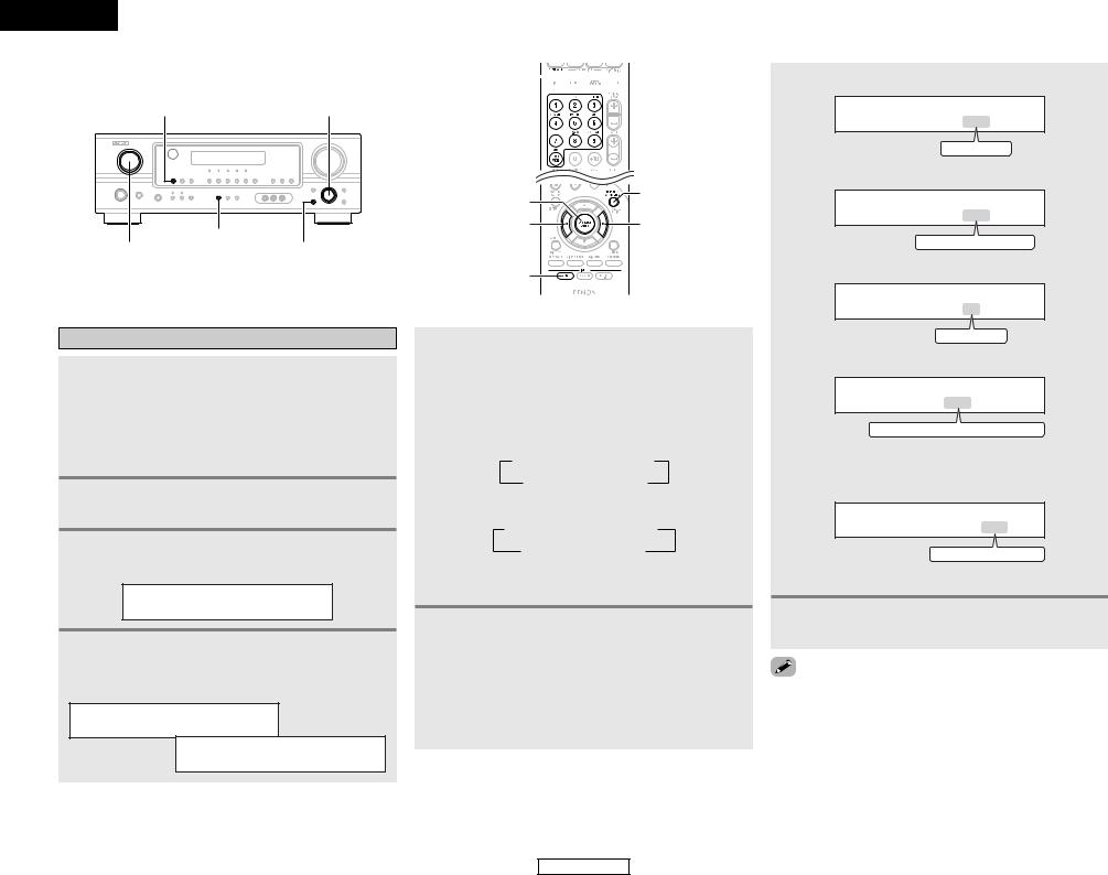
ENGLISH
Basic Operation
INPUT MODE |
SELECT |
STANDARD
INPUT SELECTOR SURROUND PARAMETER
DTS NEO:6 mode
1 Press the STANDARD button to select the DTS NEO:6 mode.

 The mode switches as shown below each time the button is pressed.
DOLBY PLII 
 DTS NEO:6
2 Play a program source.
3 Press the SURROUND PARAMETER button to select the surround parameter mode.
MODE cinema
4 Turn the SELECT knob, and press the CURSOR F or G button to select the optimum mode for the source.
MODE cinema
MODE music
STANDARD 


INPUT
SELECTOR 
ENTER |
SURROUND |
|
PARAMETER |
||
CURSOR F |
||
CURSOR G |
||
INPUT MODE |
|
5 Press the SURROUND PARAMETER button to select the various parameters.

 The mode switches as shown below each time the button is pressed.
• When the Cinema mode:
 MODE CINEMA
  CINEMA EQ
DEFAULT TONE DEFEAT
• When the Music mode:
 MODE MUSIC
  CENTER IMAGE
DEFAULT TONE DEFEAT

 If you do want the bass and treble to be adjusted, turn off the tone defeat mode.
6 Turn the SELECT knob, and press the CURSOR F or G button to set the various surround parameters.

 When the surround parameters are set using the buttons on the main unit, stop operating the buttons after completing the settings. The settings are automatically finalized and the normal display reappears after several seconds.
Basic Operation
• CINEMA EQ setting:
CINEMA EQ OFF
ON
 OFF
OFF
• CENTER IMAGE setting
C . IMAGE 0 . 3
0.0
 0.3
0.3
 1.0
1.0
• TONE DEFEAT setting
TONE DEF . ON
ON
 OFF
OFF
• D. COMP. setting
D . COMP . OFF
OFF
 LOW
LOW
 MID
MID
 HIGH
HIGH

 This parameter is displayed during DOLBY DIGITAL playback.
• DEFAULT setting
DEFAULT Y/N
YES
 Y/N
Y/N
 NO
NO

 Select “YES” to reset to the factory defaults.
7 Press the ENTER button to finish the surround parameter mode.
making parameter settings, the display will return to the condition several seconds after the last button was and the setting will be completed.
21
ENGLISH
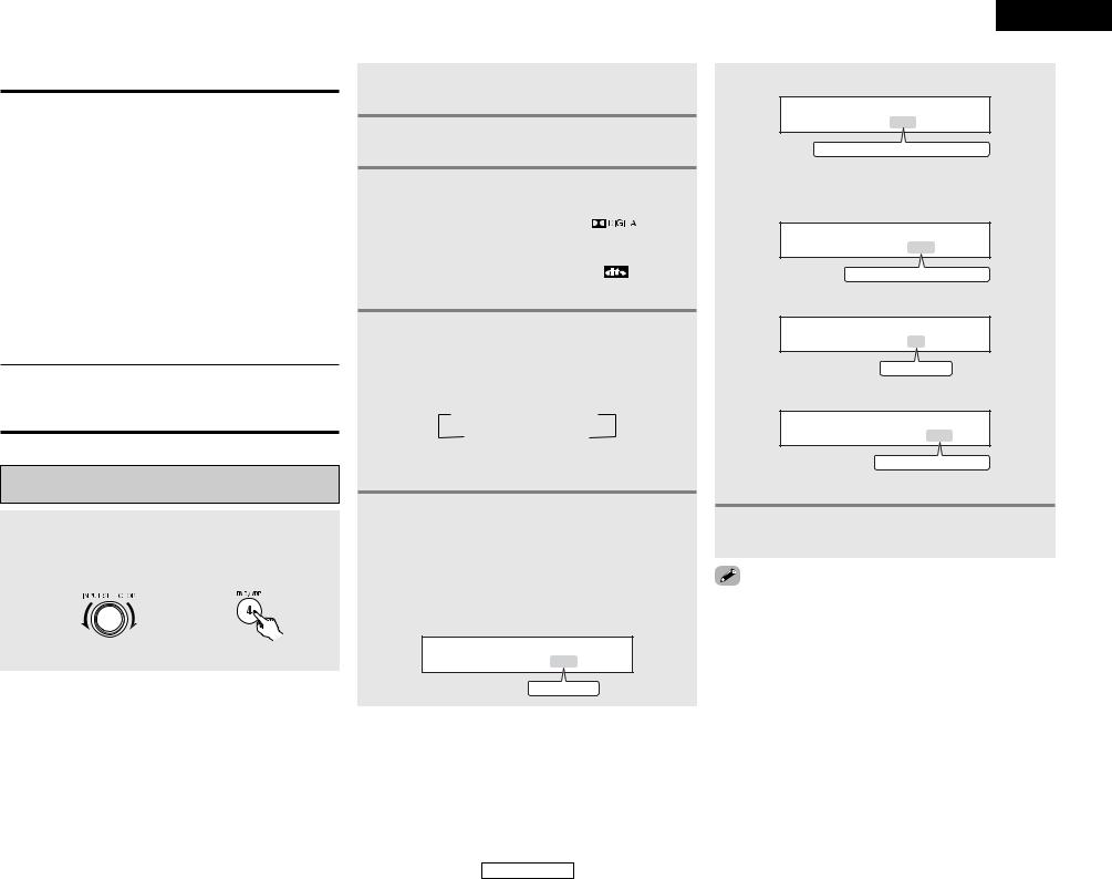
Basic Operation
2 Surround parameters w
DTS NEO:6 Mode:
•Cinema:
This mode is optimum for playing movies. Decoding is performed with emphasis on separation performance to achieve the same atmosphere with 2-channel sources as with 6.1-channel sources.
This mode is effective for playing sources recorded in conventional surround formats as well, because the in-phase component is assigned mainly to the center channel (C) and the reversed phase component to the surround (SL, SR and SB channels).
•Music:
This mode is suited mainly for playing music. The front channel (FL and FR) signals bypass the decoder and are played directly so there is no loss of sound quality, and the effect of the surround signals output from the center (C) and surround (SL, SR and SB) channels add a natural sense of expansion to the sound field.
CENTER IMAGE (0.0 to 1.0: default 0.3):
The center image parameter for adjusting the expansion of the center channel in the DTS NEO:6 MUSIC mode has been added.
Dolby Digital mode and DTS surround (only with digital input)
1 Select an input source set to digital (COAXIAL/ OPTICAL) ( page 15).
Example: DVD
(Main unit) |
(Remote control unit) |
2 Press the INPUT MODE button to set the input mode to “AUTO” or “DTS”.
3 Press the STANDARD button to select the STANDARD (Dolby/DTS Surround) mode.
4 Play a program source with the symbol.
•The Dolby Digital indicator lights when playing Dolby Digital sources.
•The DTS indicator lights when playing DTS sources.


 or
or 

 Lights

 Lights
5 Press the SURROUND PARAMETER button to select the various parameters.

 The parameter switches as shown below each time the button is pressed.
 CINEMA EQ
  D.COMP.
  LFE
LFE
DEFAULT TONE DEFEAT

 If you do want the bass and treble to be adjusted, turn off the tone defeat mode.
6 Turn the SELECT knob, and press the CURSOR F or G button to set the various surround parameters.

 The mode switches as shown below each time the button is pressed.
• CINEMA EQ setting:
CINEMA EQ OFF
ON
 OFF
OFF
22
ENGLISH
Basic Operation
• D. COMP. setting
D . COMP . OFF
OFF
 LOW
LOW
 MID
MID
 HIGH
HIGH

 This parameter is displayed during DOLBY DIGITAL playback.
• LFE setting
LFE 0dB
-10dB
 -5dB
-5dB
 0dB
0dB
• TONE DEFEAT setting
TONE DEF . ON
ON
 OFF
OFF
• DEFAULT setting
DEFAULT Y/N
YES
 Y/N
Y/N
 NO
NO

 Select “YES” to reset to the factory defaults.
7 Press the ENTER button to finish the surround parameter mode.
making parameter settings, the display will return to the condition several seconds after the last button was and the setting will be completed.
ENGLISH
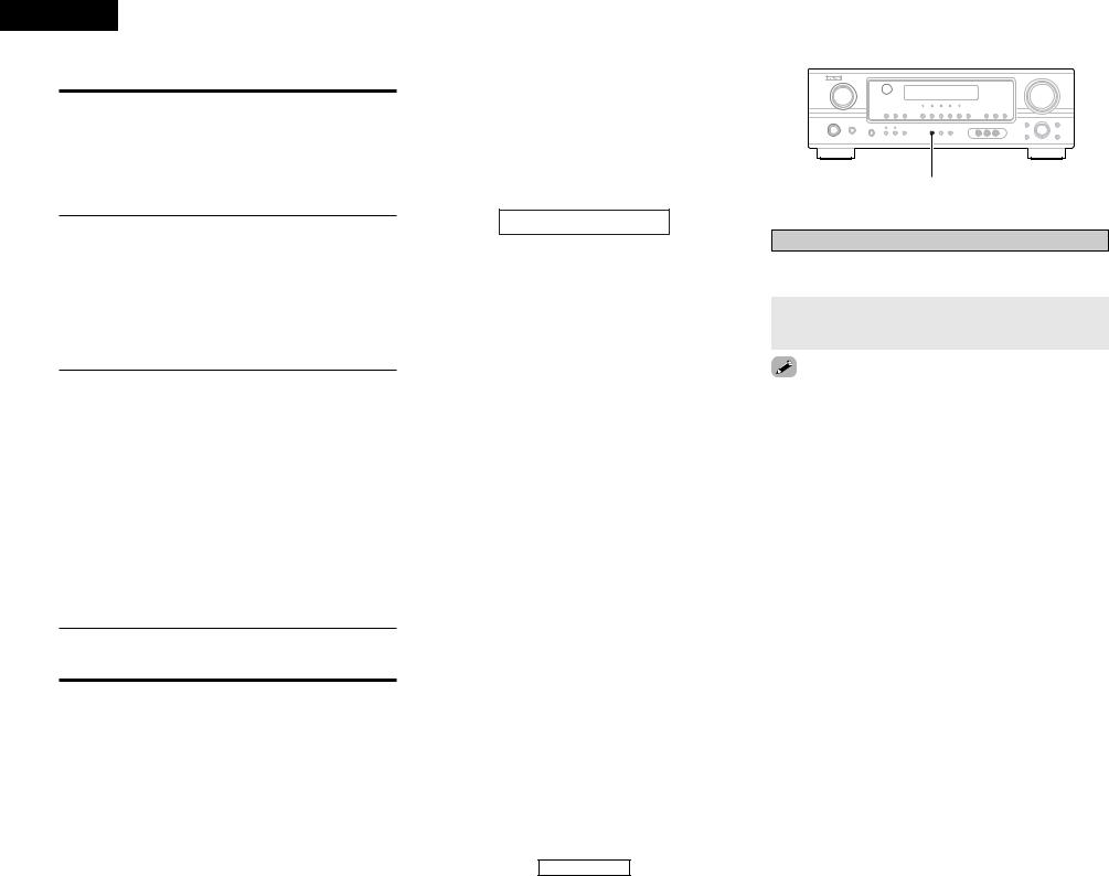
ENGLISH
Basic Operation
2 Surround parameters e
CINEMA EQ. (Cinema Equalizer):
The Cinema EQ function gently decreases the level of the extreme high frequencies, compensating for overly-bright sounding motion picture soundtracks. Select this function if the sound from the front speakers is too bright.
This function only works in the Dolby Pro Logic II, Dolby Digital, DTS Surround and DTS NEO:6 modes. (The same contents are set for all operating modes.)
D.COMP. (Dynamic Range Compression):
Motion picture soundtracks have tremendous dynamic range (the contrast between very soft and very loud sounds). For listening late at night, or whenever the maximum sound level is lower than usual, the Dynamic Range Compression allows you to hear all of the sounds in the soundtrack (but with reduced dynamic range). (This only works when playing program sources recorded in Dolby Digital or DTS). Select one of the four parameters (“OFF”, “LOW”, “MID” (middle) or “HIGH”). Set to “OFF” for normal listening.
LFE (Low Frequency Effect):
This sets the level of the LFE (Low Frequency Effect) sounds included in the source when playing program sources recorded in Dolby Digital or DTS.
If the sound produced from the subwoofer sounds distorted due to the LFE signals when playing Dolby Digital or DTS sources when the peak limiter is turned off with the subwoofer peak limit level setting, adjust the level as necessary.
Program source and adjustment range:
1.Dolby Digital: –10 dB to 0 dB
2.DTS Surround: –10 dB to 0 dB

 When DTS encoded movie software is played, it is recommended that the LFE LEVEL be set to 0 dB for correct DTS playback.

 When DTS encoded music software is played, it is recommended that the LFE LEVEL be set to –10 dB for correct DTS playback.
TONE:
This enables tone control. This can be set individually for the separate surround modes other than DIRECT mode.
2 Dialogue normalization
The dialog normalization function is activated automatically when playing Dolby Digital program sources.
Dialog normalization is a basic function of Dolby Digital which automatically normalizes the dialog level (standard level) of the signals which are recorded at different levels for different program sources, such as DVD, DTV and other future formats that will use Dolby Digital.
These contents can be verified with the STATUS button.
OFFSET - 4dB
The number indicates the normalization level when the currently playing program is normalized to the standard level.
Basic Operation
NIGHT
Night mode
When listening at night or at lower volumes, the night mode improves listenability.
Press and hold the NIGHT button for several seconds to enter the night mode.
night mode:
and hold the NIGHT button again.
night mode only works when playing program sources in Dolby Digital or DTS.
23
ENGLISH

ENGLISH
Basic Operation |
Basic Operation |
DENON original surround modes
This unit is equipped with a high performance DSP (Digital Signal Processor) which uses digital signal processing to synthetically recreate the sound field. One of 7 preset surround modes can be selected according to the program source and the parameters can be adjusted according to the conditions in the listening room to achieve a more realistic, powerful sound.
Surround modes and their features
|
|
The front left channel signals are output to the surround left channels, the front right channel signals are |
|
1 |
5CH STEREO |
output to the surround right channels, and the in-phase component of the left and right channels is output |
|
|
|
to the center channel. Use this mode to enjoy stereo sound. |
|
|
|
|
|
2 |
MONO MOVIE |
Select this when watching monaural movies for a greater sense of expansion. |
|
|
(NOTE) |
|
|
3 |
ROCK ARENA |
Use this mode to achieve the feeling of a live concert in an arena with reflected sounds coming from all |
|
directions. |
|||
|
|
||
|
|
|
|
4 |
JAZZ CLUB |
This mode creates the sound field of a live house with a low ceiling and hard walls. This mode gives jazz |
|
a very vivid realism. |
|||
|
|
||
|
|
|
|
5 |
VIDEO GAME |
Use this to enjoy video game sources. |
|
|
|
|
|
|
|
Select this to emphasize the sense of expansion for music sources recorded in stereo. Signals consisting |
|
6 |
MATRIX |
of the component difference of the input signals (the component that provides the sense of expansion) |
|
|
|
processed for delay are output from the surround channel. |
|
|
|
|
|
7 |
VIRTUAL |
Select this mode to enjoy a virtual sound field, produced from the front 2-channel speakers or headphones. |
|
|
|
|

 Depending on the program source being played, the effect may not be very noticeable.
In this case, try other surround modes, without worrying about their names, to create a sound field suited to your tastes.
NOTE: When playing sources recorded in monaural, the sound will be one-sided if signals are only input to one channel (left or right), so input signals to both channels. If you have a source component with only one audio output (monophonic camcorder, etc.) obtain a “Y” adapter cable to split the mono output to two outputs, and connect to the L and R inputs.
2 Personal memory plus
This set is equipped with a personal memorize function that automatically memorizes the surround modes and input modes selected for the different sources. When the input source is switched, the modes set for that source last time it was used are automatically recalled.

 The surround parameters, tone control settings and playback level balance for the different output channels are memorized for each surround mode.
24
ENGLISH
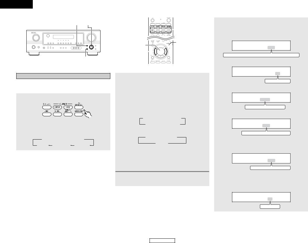
ENGLISH
Basic Operation
SURROUND MODE SELECT
SURROUND PARAMETER
DSP surround simulation
2To operate the surround mode and the surround parameters from the remote control unit
1 Select the surround mode for the input channel.
(Remote control unit)

 The surround mode switches in the following order each time the DSP SIMULATION button is pressed:
 MONO MOVIE
  ROCK ARENA
MATRIX |
VIDEO GAME |
JAZZ CLUB |


 SURROUND
MODE


 SURROUND
ENTER 


 PARAMETER
CURSOR F 


 CURSOR G
2 Press the SURROUND PARAMETER button to enter the surround parameter setting mode.

 The surround parameter switches in the following order each time the SURROUND PARAMETER button is pressed for the different surround modes.
•When the MONO MOVIE, ROCK ARENA, JAZZ CLUB and VIDEO GAME mode:
 ROOM SIZE
  EFFECT LEVEL
DEFAULT TONE DEFEAT
• When the MATRIX mode:
 DELAY
DELAY  TONE DEFEAT
DEFAULT
• When the VIRTUAL mode:
TONE DEFEAT
 DEFAULT

 If you do want the bass and treble to be adjusted, turn off the tone defeat mode.
3 Press the SURROUND PARAMETER button to select the various parameters.
Basic Operation
4 Press the CURSOR F or G button to set the various parameters.
• ROOM SIZE setting:
ROOM SIZE MED
SMALL
 MED-S
MED-S
 MED
MED
 MED-L
MED-L
 LARGE
LARGE
• EFFECT LEVEL setting
EFFECT LEVEL 10
1
 10
10
 15
15
• DELAY TIME setting
DELAY 30ms
0ms
 30ms
30ms
 110ms
110ms
• D. COMP. setting
D . COMP . OFF
OFF
 LOW
LOW
 MID
MID
 HIGH
HIGH

 This parameter is displayed during DOLBY DIGITAL playback.
• LFE setting
LFE 0dB
-10dB
 -5dB
-5dB
 0dB
0dB

 This parameter is displayed during DOLBY DIGITAL and DTS playback.
• TONE DEFEAT setting
TONE DEF . ON
ON
 OFF
OFF
25
ENGLISH
 Loading...