


 Loading...
AV SURROUND AMPLIFIER
AVC-A1HD
AV SURROUND PRE-AMPLIFIER
AVP-A1HD
Owner’s Manual GUpgrade versionH
The owner’s manual is organized in the following two volumes.
•GOriginal versionH
•GUpgrade versionH································This version
NOTE
•Products that have been upgraded cannot be returned to the previous state.
•This model has been upgraded previously. This manual contains details of all of the upgrades. Therefore, you do not need any manuals other than the “Original version” and “Upgrade version” (this version).
n Symbols used in this manual
AVC-A1HD |
This symbol indicates contents for AVC-A1HD. |
AVP-A1HD |
This symbol indicates contents for AVP-A1HD. |
|
This symbol indicates items described in the |
|
“Original version”. |
Contents
Getting Started
Accessories······················································································2
Functions that are added/changed/deleted by this upgrade·······2, 3
Changes to the Panel Display·························································4
Front Panel······················································································4 Rear Panel·······················································································4 Part Names and Functions·····························································5
Front Panel······················································································5 Display····························································································5 Remote Control Unit·······································································6
Connections
Speaker Installation········································································6
Speaker Layout ··············································································6
Speaker Connections···································································7, 8
Connecting Equipment with HDMI connectors···························9
Connections to Other Devices·······················································9
External Power Amplifier································································9
GUI Menu Operations
GUI Menu Map··········································································10,11
Auto Setup
Auto Setup··············································································· 12, 13
a Auto Setup·······································································14 ~ 21
s Option······················································································22
d Parameter Check·····································································22
Manual Setup
Speaker Setup···············································································23
a Speaker Configuration·····························································23
s Subwoofer Setup·····································································24
d Distance··················································································24
fChannel Level····································································24, 25
gCrossover Frequency·······························································25
hTHX Audio Setup·····································································25
Audio Setup···················································································26
aEXT. IN Setup···········································································26
s2ch Direct/Stereo·······························································26, 27
dAuto Surround Mode·······························································27
fManual EQ···············································································27 Option Setup·················································································28
a Amp Assign ( |
AVC-A1HD only)··············································28 |
||||
a Pre-out Assign ( |
|
AVP-A1HD |
|
only)··········································29 |
|
s XLR Out Polarity ( |
AVP-A1HD |
only)·······································30 |
|||
d POA Setting ( AVP-A1HD |
only)··············································30 |
||||
s Volume Control ( |
AVP-A1HD |
: f)··········································30 |
|||
d Source Delete ( |
AVP-A1HD |
|
: g)············································30 |
||
f GUI ( AVP-A1HD |
|
: h)····························································31 |
|||
g Quick Select Name ( AVP-A1HD : j)····································31 |
|||||
h Trigger Out 1 ( |
AVP-A1HD |
: k)··············································32 |
|||
j Trigger Out 2 |
( |
AVP-A1HD |
: l)··············································32 |
||
k Trigger Out 3 |
( |
AVP-A1HD |
: A0)··············································32 |
||
l Trigger Out 4 |
( |
AVP-A1HD |
: A1)··············································32 |
||
A0Transducer Setup ( |
AVP-A1HD |
: A2)·······································32 |
||
A1Digital Out ( |
AVP-A1HD |
: A3)·················································33 |
||
A2Remote ID ( |
AVP-A1HD |
: A4)·················································33 |
||
A3232C Port (1) ( AVP-A1HD |
: A5)··············································33 |
|||
A4Dimmer ( AVP-A1HD |
: A6)······················································33 |
|||
A5Setup Lock ( |
AVP-A1HD |
: A7)·················································33 |
||
A6Maintenance Mode ( AVP-A1HD |
: A8)···································33 |
|||
A7Firmware Update ( |
AVP-A1HD |
: A9)·······································34 |
||
A8Add New Feature ( |
AVP-A1HD |
: S0)·······································34 |
||
Surround Mode
HOME THX CINEMA······································································35
Surround Playback of 2-channel Sources······································35 Playing Multi-channel Sources (Dolby Digital, DTS, etc.)··············35 Standard Playback········································································36
Surround Playback of 2-channel Sources······································36 Playing Multi-channel Sources (Dolby Digital, DTS, etc.)··············37
Parameters
Audio······························································································38
a Surround Parameters·······················································38 ~ 40
s Tone·························································································40
d Audyssey Settings·····························································41, 42
fA-DSX Soundstage····························································42, 43
gRESTORER··············································································43
hAudio Delay·············································································43
Information
Status·····························································································44
a MAIN ZONE·············································································44
s ZONE2/3/4···············································································44
Quick Select···················································································44
Other Operations and Functions················································45
Amp Assign / Multi-Zone Connections and Operations
( AVC-A1HD only)································································ 46 ~ 61
Other Information······························································· 62 ~ 69
Troubleshooting·····································································70, 71
Specifications···············································································72
Specifications Troubleshooting Information Zone-Multi Operations Other Setup Connections Started Getting
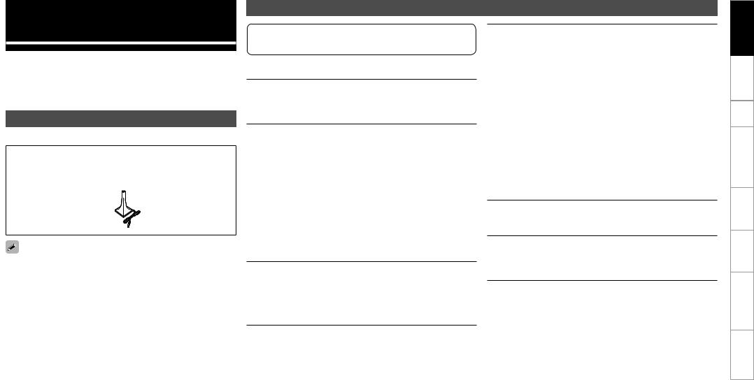
Getting Started
Thank you for purchasing this DENON product. To ensure proper operation, please read this owner’s manual carefully before using the product.
After reading them, be sure to keep them for future reference.
Accessories |
|
Check that the following parts are supplied with the product. |
|
q CD-ROM (Owner’s manual)..................................................... |
1 |
w Setup microphone (DM-A409, Cord length: Approx. 6.0 m).... |
1 |
w
Note that the illustrations in this instructions are for explanation purposes and may differ from the actual unit.
Functions that are added/changed/deleted by this upgrade
When this product is upgraded, all settings return to the default settings. Reconfigure settings as required.
Additional functions
Audyssey Dynamic Volume®
Audyssey Dynamic Volume® is technology that solves the problem of large variations in volume level between television programs, commercials, and between the soft and loud passages of movies.
DENON LINK 4th (Jitter-free playback)
DENON LINK 4th adds high-quality playback of HD audio in addition to the outstanding performance of DENON LINK 3rd, high quality audio signal transmission technology developed by DENON.
By connecting an AV amplifier and Blu-ray Disc player that both support DENON LINK 4th with a DENON LINK cable (supplied with the Blu-ray Disc player) and HDMI cable (sold separately), you can control the Blu-ray Disc player using the master clock signal sent from the AV amplifier.
As D/A conversion is performed by the AV amplifier master clock, there are no effects of clock jitter from the HDMI transfer, enabling jitter free playback.
Sound localization becomes clearer, producing the clear sense of space in the sound images that can only be achieved from HD audio.
Audyssey DSX™
By connecting front height speakers to this unit and playing back through Audyssey DSX™, you can experience a more powerful playback expression in the height audio range. By connecting front wide speakers, you can experience a more powerful playback expression in the wide audio range.
Dolby Pro Logic gz
Dolby Pro Logic gz introduces a new dimension to Home Entertainment through the addition of a pair of front height channels. Compatible with stereo, 5.1-channel and 7.1-channel content, Dolby Pro Logic gz provides enhanced spaciousness, depth and dimension to movies, concert video and video game playback while maintaining the full integrity of the source mix.
Dolby Pro Logic gz identifies and decodes spatial cues that occur naturally in all content, directing this information to the front height channels, complementing the performance of left and right surround sound speakers. Content that is encoded Explanation of terms with Dolby Pro Logic gz height channel information can be even more revealing, with perceptually discrete height channel information bringing an exciting new dimension to home entertainment.
Dolby Pro Logic gz, with front height channels is also an ideal alternative for households that cannot support the placement of back surround speakers of a typical 7.1-channel system but may have bookshelf space available to support the addition of height speakers.
HDMI (Ver. 1.4a with 3D)
This unit can output 3D video signals input from a Blu-ray Disc player to a TV that supports a 3D system.
DTS Neo:X
This technology enables the playback of 2-channel source audio or 7.1/5.1 multi-channel source audio through a maximum 9.1 channel speakers, achieving an even broader sound field.
Specifications Troubleshooting Information Zone-Multi Operations Other Setup Connections Started Getting
Changed Functions
Support for front height speakers and front wide speakers
Front height or front wide channels can be played back through the FH/FW/AMP ASSIGN-2 speaker terminals and the PRE OUT FH/FW terminals.This enables you to enjoy a maximum 9.3 channel surround playback.
Audyssey MultEQ® XT 32
Audyssey MultEQ® corrects both time and frequency response problems in the listening area so that every listener can enjoy music and movie with the optimum sounds. It performs a fully automated surround system setup. The unit is equipped Audyssey MultEQ® XT 32 that can correct much higher details, particularly in the bass range of the speakers. The high resolution correction reproduces much clearer surround sound.
Direct Mode function (Multi-channel)
When multi-channel signals are input, the signals are output directly without being mixed-down to 2 channels.
Surround Back function
When surround back speakers are used and a surround back signal is recorded in the input signal, audio is output automatically from the surround back speakers.
Web Control function
When this product is upgraded, previously saved contents cannot be called.
After completing the upgrade, reconfigure the settings.
For details on the web control operating procedures, see mpage 61 , mpage 63 .
Deleted Functions
Surround B speakers unsupported
As front height speakers and front wide speakers are now supported by this upgrade, surround B speakers can no longer be used.
Audyssey MultEQ® XT
As Audyssey MultEQ® XT 32 is supported by this upgrade, Audyssey MultEQ® XT is deleted.
DTS Neo:6
As DTS Neo:X is supported by this upgrade, DTS Neo:6 is deleted.
Night Mode function
In this upgrade, the night mode in which the volume can be set to low level for listening at nighttime is deleted. The same effect can be obtained from setting “Dynamic EQ®” and “Dynamic Volume®” in the GUI menu (vpage 41) to “ON”.
Mic Select function
The Mic Select function is deleted when the product is upgraded. Only the supplied setup microphone (DM-A409) can be used.
For details on the items that are added/changed/deleted from the GUI menu, see “GUI Menu Map” (vpage 10, 11).
Specifications Troubleshooting Information Zone-Multi Operations Other Setup Connections Started Getting
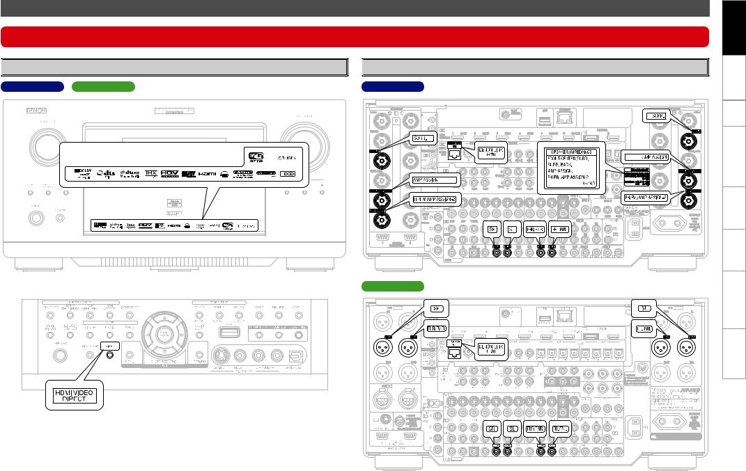
Changes to the Panel Display
After completing the upgrade, labels are attached to the changed parts of the panel. For details of the changed parts, see the illustration below.

 Front Panel
AVC-A1HD AVP-A1HD

 Rear Panel
AVC-A1HD |
GWith the door openH |
AVP-A1HD |
Specifications Troubleshooting Information Zone-Multi Operations Other Setup Connections Started Getting
Part Names and Functions

 Front Panel
When this unit is upgraded, the night mode cannot be set when the NIGHT button is pressed.
GWith the door openH
q
q HDMI video direct button (HDMI VIDEO DIRECT)
When this button is pressed, video signals recorded on the BD or DVD are output directly. Video signals input from the HDMI IN terminal are output directly from the HDMI OUT terminal without being processed by this unit.
When the video direct function is on, temporary display in the GUI menu cannot be used.

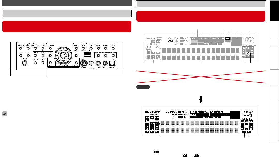
 Display
When the upgrade is performed, the sections highlighted in the illustration below do not light.
|
Q8 |
Q6 |
Q4 |
Q2Q0 |
y |
|
Q7Q5 |
Q3Q1 o i u |
|||
q |
w |
e |
|
r t |
|
t Surround speaker indicators |
Q1NIGHT indicator |
These light according to the settings of the |
This lights when the night mode is selected. |
surround A and B speakers. |
|
NOTE
The NEO:6 indicator does not light after the upgrade because DTS NEO:X is supported.
q
q Input signal channel indicators
When there is 1 extension channel in the input
signal, the |
indicator lights. If there are two |
|
or more extension channels, the |
and |
|
indicators light. |
|
|
w e
w Front height speaker indicator
This lights when audio signals are being output from the front height speakers.
e Front wide speaker indicator
This lights when audio signals are being output from the front wide speakers.
Specifications Troubleshooting Information Zone-Multi Operations Other Setup Connections Started Getting

 Remote Control Unit
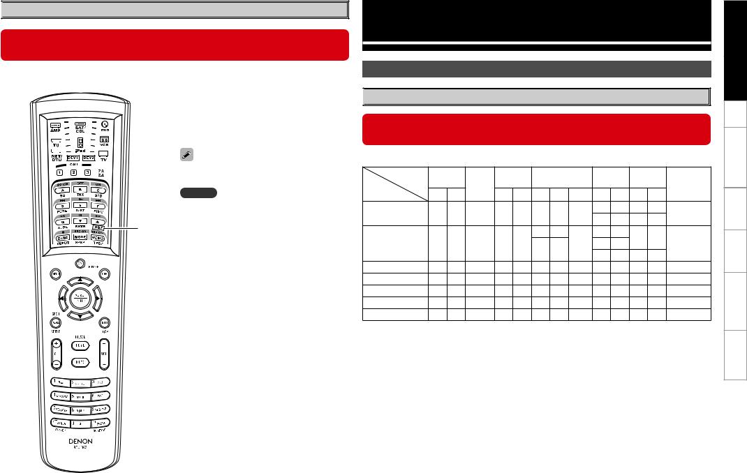
When this unit is upgraded, the night mode cannot be set when the NGT button is pressed.
n Main remote control unit (RC-1067)
q HDMI video direct button (NGT)
When this button is pressed, video signals recorded on the BD or DVD are output directly. Video signals input from the HDMI IN terminal are output directly from the HDMI OUT terminal without being processed by this unit.
When the video direct function is on, temporary display in the GUI menu cannot be used.
NOTE
When using 3D video devices that transmit radio communication signals (such as infrared signals etc) between the various units (such as the monitor, 3D
q glasses, 3D transmitter unit etc), the remote control unit may not operate due to interference from those radio communication signals. If this occurs, adjust the direction and distance of the 3D communication for each unit, and check that the remote control unit operation is not affected by these signals.
Connections
Speaker Installation

 Speaker Layout
When this unit is upgraded, the speaker configurations supported by this unit change.
The table below shows a typical speaker configuration for the unit.
Speaker |
FRONT |
|
SURROUND |
SURROUND BACK |
FRONT |
FRONT |
SUBWOOFER |
|||||||
|
CENTER |
HEIGHT |
WIDE |
|||||||||||
|
|
|
|
|
|
|
|
(b2) |
||||||
Configuration |
L |
R |
|
L |
R |
L |
R |
1 only |
L |
R |
L |
R |
||
|
|
|||||||||||||
9.1-channels (b1) |
S |
S |
S |
S |
S |
S |
S |
– |
S |
S |
– |
– |
S |
|
– |
– |
S |
S |
|||||||||||
|
|
|
|
|
|
|
|
|
|
|||||
|
|
|
|
|
|
S |
S |
|
– |
– |
– |
– |
|
|
7.1-channels |
S |
S |
S |
S |
S |
|
|
– |
S |
S |
S |
|||
– |
– |
|
|
|||||||||||
|
|
|
|
|
|
|
– |
– |
S |
S |
|
|||
|
|
|
|
|
|
|
|
|
|
|||||
6.1-channels |
S |
S |
S |
S |
S |
– |
– |
S |
– |
– |
– |
– |
S |
|
5.1-channels |
S |
S |
S |
S |
S |
– |
– |
– |
– |
– |
– |
– |
S |
|
3.1-channels |
S |
S |
S |
– |
– |
– |
– |
– |
– |
– |
– |
– |
S |
|
2.1-channels |
S |
S |
– |
– |
– |
– |
– |
– |
– |
– |
– |
– |
S |
|
2-channels |
S |
S |
– |
– |
– |
– |
– |
– |
– |
– |
– |
– |
– |
|
b1 To perform the 9.1 channel playback using front height speakers or front wide speakers, a separate power amplifier (sold separately) is required.
b2 The unit can be connected to a maximum of 3 subwoofers.
Specifications Troubleshooting Information Zone-Multi Operations Other Setup Connections Started Getting


 Speaker Connections
When this unit is upgraded, the terminal names and connection methods change.
•When using just one surround back speaker, connect it to the left channel (SBL).
•When using Subwoofer 2 or 3, set GUI menu “Manual Setup” – “Speaker Setup” – “Subwoofer Setup” (vpage 24).
AVC-A1HD
Front |
|
|
|
|
|
|
|
Front |
speaker (R) |
|
Subwoofer 1 |
|
Subwoofer 3 |
|
Subwoofer 2 |
|
speaker (L) |
b L : Left |
|
Center |
Subwoofer |
|
|
|
|
|
R : Right |
|
speaker |
|
|
|
|
||
|
with built-in |
|
|
|
|
|||
|
|
|
|
|
|
|
|
|
|
(R) |
|
|
amplifier |
|
|
|
(L) |
|
|
|
|
|
|
|
||
w |
q |
w |
q |
|
*/ |
|
w |
q |
|
|
|
|
|
*/ |
*/ |
|
|
|
|
|
|
R |
L |
|
|
|
|
|
|
|
Power amplifier |
R |
L |
|
|
|
|
|
|
|
|
|
||
(R) |
(R) |
(R) |
|
|
|
(L) |
(L) |
(L) |
|
|
|
|
|
*/ |
|
|
|
w q |
w q |
w q |
|
|
|
w q |
w q |
w |
Surround |
|
Front height |
|
Surround |
|
Front height |
|
Surround |
|
Front height |
|
Surround |
speaker |
|
speaker |
|
back |
|
speaker |
|
back |
|
speaker |
|
speaker |
(R) |
|
(R) |
|
speaker |
|
(L/R) |
|
speaker |
|
(L) |
|
(L) |
|
|
|
|
(R) |
|
|
|
(L) |
|
|
|
|
|
|
or |
|
or |
|
or |
|
|||||
|
|
|
|
|
|
|
||||||
|
|
|
|
|
|
|
|
|
|
|
|
|
|
|
Front wide |
|
|
|
Front wide |
|
|
|
Front wide |
|
|
|
|
speaker |
|
|
|
speaker |
|
|
|
speaker |
|
|
|
|
(R) |
|
|
|
(L/R) |
|
|
|
(L) |
|
|
NOTE |
|
|
|
|
|
|
|
NOTE |
|
|
|
|
|
|
|
|
|
|
|
|
|
|
|
||
It is not possible to use the front height speakers |
It is not possible to use the front height speakers |
and front wide speakers simultaneously. |
and front wide speakers simultaneously. |
Specifications Troubleshooting Information Zone-Multi Operations Other Setup Connections Started Getting

AVP-A1HD |
|
|
|
|
|
|
|
|
|
|
|
|||
n Connecting the RCA pre-out terminal (Example : 9.3-channels) |
|
|
||||||||||||
|
|
|
|
|
Subwoofer 1 |
|
Subwoofer 2 |
|
Subwoofer 3 |
|
||||
b L : Left |
|
|
|
|
|
|
|
|
|
|
|
|
|
|
R : Right |
|
|
Subwoofer |
|
|
|
|
|
|
|
|
|
||
|
|
|
|
|
|
|
|
|
|
|
|
|
||
|
|
|
|
with built-in |
|
|
|
|
|
|
|
|
|
|
|
|
|
|
amplifier |
|
|
|
|
|
|
|
|
|
|
This unit |
|
|
*/ |
|
|
|
*/ |
|
*/ |
|
|
|||
|
|
|
|
|
|
|
|
|
|
|
||||
|
|
|
|
|
|
|
|
|
|
|
|
POA-A1HD |
|
|
|
RCA |
|
RCA |
RCA |
RCA |
RCA |
|
RCA |
RCA |
RCA |
RCA |
RCA |
|
|
|
XLR |
|
XLR |
XLR |
XLR |
XLR |
|
XLR |
XLR |
XLR |
XLR |
XLR |
|
|
|
SPEAKERS |
SPEAKERS |
SPEAKERS |
SPEAKERS |
SPEAKERS |
|
SPEAKERS |
SPEAKERS |
SPEAKERS |
SPEAKERS |
SPEAKERS |
|
|
|
(R) |
|
|
(R) |
(R) |
|
(R) |
w |
q |
(L) |
(L) |
|
(L) |
|
(L) |
w |
q |
|
|
|
|
|
|
|
|
|
w |
q |
||
|
w q |
w q w q |
|
|
w q w q |
w q |
||||||||
|
|
|
|
|
|
|
||||||||
Front |
|
Front height/ |
Surround |
Surround |
Center |
Surround |
Surround |
Front height/ |
|
Front |
||||
speaker |
Front wide |
speaker |
|
back |
speaker |
back |
speaker |
Front wide |
speaker |
|||||
(R) |
|
|
speaker |
(R) |
speaker |
|
|
speaker |
(L) |
|
speaker |
|
(L) |
|
|
|
|
(R) |
|
|
(R) |
|
|
(L) |
|
|
(L) |
|
|
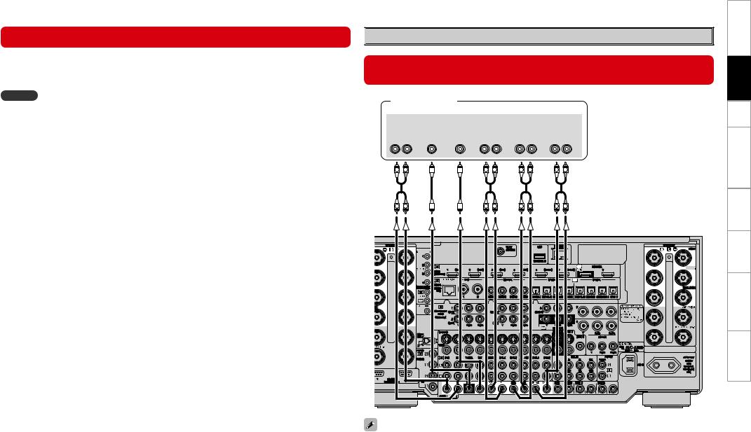
n Connecting the XLR pre-out terminal (Example : 9.3-channels)
Subwoofer 3 |
|
Subwoofer 2 |
|
Subwoofer 1 |
|
|
|
|
|
|
|
|
|
|
|
|
Subwoofer with |
|
|
|
|
|
|
|
|||
|
|
|
|
|
|
|
built-in amplifier |
|
|
|
|
|
|
|
|||
|
|
|
|
IN |
|
|
|
|
|
IN |
|
|
|
IN |
|
|
|
This unit |
|
|
|
|
|
|
|
|
|
|
|
|
|
|
|
|
|
|
|
|
|
|
|
|
|
|
|
|
|
|
|
POA-A1HD |
|
|
|
|
XLR |
|
XLR |
XLR |
|
XLR |
XLR |
|
XLR |
XLR |
|
XLR |
XLR |
|
XLR |
|
|
|
SPEAKERS |
SPEAKERS |
SPEAKERS |
|
SPEAKERS |
SPEAKERS |
|
SPEAKERS |
SPEAKERS |
SPEAKERS |
SPEAKERS |
SPEAKERS |
|
|
|||
(R) |
|
|
(R) |
(R) |
|
|
(R) |
w |
q |
|
(L) |
|
(L) |
|
(L) |
|
(L) |
w |
q |
|
|
|
|
|
|
|
|
|
|
|
|
w |
q |
||
w |
q |
w |
q |
|
|
|
|
w |
q |
w |
q |
w |
q |
||||
|
|
|
|
|
|
|
|
||||||||||
Front |
|
Front height/ |
Surround |
Surround |
Center |
Surround |
Surround |
Front height/ |
|
Front |
|||||||
speaker |
Front wide |
speaker |
|
back |
speaker |
|
back |
speaker |
Front wide |
speaker |
|||||||
(R) |
|
speaker |
(R) |
|
speaker |
|
|
speaker |
|
(L) |
speaker |
|
(L) |
||||
|
|
|
(R) |
|
|
|
(R) |
|
|
|
(L) |
|
|
|
(L) |
|
|
NOTE
The default AVP-A1HD balance model XLR pre-out terminal pin alignment is as shown. q : GROUND w : HOT e : COLD
Specifications Troubleshooting Information Zone-Multi Operations Other Setup Connections Started Getting
Connecting Equipment with HDMI connectors |
|
Connections to Other Devices |
When this unit is upgraded, 3D video can be played back.
This unit supports input and output of 3D (3 dimensional) video signals of HDMI 1.4a.
To play back 3D video, you need a TV and player that provide support for the HDMI 1.4a 3D function and a pair of 3D glasses.
NOTE
•When playing back 3D video, refer to the instructions provided in the manual of your playback device together with this manual.
•If you operate the menu while playing back 3D video content, the playback video is replaced by the menu screen. The playback video is not displayed behind the menu screen.
•This unit does not show the status display while playing back 3D video content.
•If 3D video with no 3D information is input, the menu screen and status display on this unit are displayed over the playback video.
•If 2D video is converted to 3D video on the television, the menu screen and status display on this unit are not displayed correctly. To view the menu screen and status display on this unit correctly, turn the television setting that converts 2D video to 3D video off.
•When computer resolution (e.g. VGA) video or 3D video contents are being played back, the status display cannot be displayed.
•When the menu is operated during playback of a computer resolution video (e.g. VGA) or 3D video contents, the playback video switches to the video in the menu screen.
•When a 3D compatible television and 3D incompatible television are connected at the same time, when you want to playback 3D video, switch the “Monitor Out” (vmpage 31) setting to the terminals that the 3D compatible television is connected to before playing the content on the player.

 External Power Amplifier
When this unit is upgraded, the terminal names and connection methods will change.
Power amplifier
|
|
|
"6%*0 |
|
|
|
|
|
|
|
|
'30/5 |
46# |
$&/5&3 463306/% 463306/% |
'30/5 )&*()5 |
||
|
800'&3 |
#"$, |
or |
||
|
|
|
|
|
|
'30/5 8*%& |
|
- |
3 |
- |
3 |
- |
3 |
- |
3 |
L |
R |
L |
R |
L |
R |
L |
R |
L |
R |
L |
R |
L |
R |
L |
R |
When using just one surround back speaker, connect it to the left channel (SBL).
Specifications Troubleshooting Information Zone-Multi Operations Other Setup Connections Started Getting
GUI Menu Operations
Information |
AVC-A1HD |
|
|
(vpage 44) |
|
nStatus
•MAIN ZONE
•ZONE2/3/4
n Audio Input Signal
n HDMI Information
n Auto Surround Mode
n Quick Select
n Preset Station
Surround Mode
(vpage 35 ~ 37)
n STEREO n DIRECT
n STANDARD
n DOLBY HEADPHONE
(When using headphones)
n DOLBY PLIIx, DOLBY PLII or
DOLBY PL n DOLBY PLIIz n DTS NEO:6 n DTS NEO:X
n HOME THX CINEMA n 7CH STEREO
n WIDE SCREEN n SUPER STADIUM n ROCK ARENA
n JAZZ CLUB
n CLASSIC CONCERT n MONO MOVIE
n VIDEO GAME n MATRIX
Auto Setup
(vpage 12 ~ 22)
n Auto Setup
• STEP1 Preparation
• STEP2 Detection & Measurement (main)
•STEP3 Measurement (2nd – 8th)
•STEP4 Calculation
•STEP5 Check
•STEP6 Store
•Finish
nOption
•Room EQ
•Direct Mode
•Mic Select
n Parameter Check
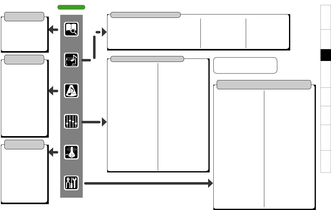
GUI Menu Map
Source Select (vmpage 42 ~ 45)
n DVD, HDP, TV/CBL, SAT, VCR, DVR-1, DVR-2,V.AUX, CD,TUNER |
n NET/USB |
n PHONO |
|
• Play (iPod) |
• Input Mode |
• Play |
• Video |
• Playback Mode (iPod) |
• Rename |
• Playback Mode |
• Input Mode |
• Assign |
• Source Level |
• Still Picture |
• Rename |
• Video |
|
• Video |
• Source Level |
|
|
• Input Mode |
|
|
|
• Rename |
|
|
|
• Source Level |
|
Parameters (vpage 38 ~ 43, mpage 52)
n Audio |
|
• Surround Parameters |
• Tone |
· Mode |
· Tone Defeat |
· Decoder |
· Bass |
· Cinema EQ |
· Treble |
· DRC |
· Front |
· D.COMP |
· Center |
· LFE |
· Surround |
· Center Image |
· Surround Back |
· Center Gain |
· Front Height |
· Panorama |
· Front Wide |
· Dimension |
· Subwoofer |
· Center Width |
• Room EQ |
· Delay Time |
• Audyssey Settings |
· Effect |
· MultEQ® XT 32 |
· Effect Level |
· Dynamic EQ® |
· Room Size |
· Reference Level Offset |
· AFDM |
· Dynamic Volume® |
· SB CH Out |
· Setting |
· Height Gain |
• A-DSX Soundstage |
· Subwoofer Att. |
· Audyssey DSX™ |
· Subwoofer |
· Stage Width |
· Default |
· Stage Height |
|
• RESTORER |
|
• Night Mode |
|
• Audio Delay |
|
n Picture Adjust |
|
• Contrast |
|
• Brightness |
|
• Chroma Level |
|
• Hue |
|
• DNR |
|
• Enhancer |
|
• Sharpness |
GCharacter colorH
Blue characters : Changed or added
Red characters : Deleted
Manual Setup
(vpage 23 ~ 28, 30 ~ 34, mpage 31, 33 ~ 37, 41)
n Speaker Setup |
n Network Setup |
(vpage 23 ~ 25) |
(vmpage 33 ~ 36) |
• Speaker Configuration |
n Zone Setup (vmpage 37) |
· Front |
n Option Setup |
· Center |
(vpage 28, 30 ~ 34) |
· Subwoofer |
• Amp Assign |
· Surround A |
• Volume Control |
· Surround B |
• Source Delete |
· Surround |
• GUI |
· Surround Back |
· Screensaver |
· Front Height |
· Wall Paper |
· Front Wide |
· Format |
• Subwoofer Setup |
· Text |
• Distance |
· Master Volume |
• Channel Level |
· NET/USB |
· Mode |
· iPod |
· Surround |
• Quick Select Name |
· Start |
• Trigger Out 1 |
· Default |
• Trigger Out 2 |
• Crossover Frequency |
• Trigger Out 3 |
• THX Audio Setup |
• Trigger Out 4 |
• Surround Speaker |
• Transducer Setup |
n HDMI Setup (vmpage 31) |
• Digital Out |
n Audio Setup (vpage 26, 27) |
• Remote ID |
• EXT. IN Setup |
• 2Way Remote |
· Surround Speaker |
• 232C Port (1) |
· Subwoofer Level |
• Dimmer |
• 2ch Direct/Stereo |
• Setup Lock |
• Downmix Option |
• Maintenance Mode |
• Auto Surround Mode |
• Firmware Update |
• Manual EQ |
• Add New Feature |
|
n Language (vmpage 41) |
Specifications Troubleshooting Information Zone-Multi Operations Other Setup Connections Started Getting
10
Information
(vpage 44)
nStatus
•MAIN ZONE
•ZONE2/3/4
n Audio Input Signal
n HDMI Information
n Auto Surround Mode
n Quick Select
n Preset Station
Surround Mode
(vpage 35 ~ 37)
n STEREO n DIRECT
n STANDARD
n DOLBY HEADPHONE
(When using headphones)
n DOLBY PLIIx, DOLBY PLII or
DOLBY PL n DOLBY PLIIz n DTS NEO:6 n DTS NEO:X
n HOME THX CINEMA n 7CH STEREO
n WIDE SCREEN n SUPER STADIUM n ROCK ARENA
n JAZZ CLUB
n CLASSIC CONCERT n MONO
n VIDEO GAME n MATRIX
Auto Setup
(vpage 12 ~ 22) n Auto Setup
•STEP1 Preparation
•STEP2 Detection & Measurement (main)
•STEP3 Measurement (2nd – 8th)
•STEP4 Calculation
•STEP5 Check
•STEP6 Store
•Finish
nOption
•Room EQ
•Direct Mode
•Mic Select
n Parameter Check
AVP-A1HD
Source Select (vmpage 44 ~ 48)
n DVD, HDP, TV/CBL, SAT, VCR, DVR-1, DVR-2,V.AUX, CD,TUNER |
n NET/USB |
n PHONO |
|
• Play (iPod) |
• Input Mode |
• Play |
• Video |
• Playback Mode (iPod) |
• Rename |
• Playback Mode |
• Input Mode |
• Assign |
• Source Level |
• Still Picture |
• Rename |
• Video |
• Input Att. |
• Video |
• Source Level |
|
|
• Input Mode |
• Input Att. |
|
|
• Rename |
|
|
|
• Source Level |
|
Parameters (vpage 38 ~ 43, mpage 54)
n Audio |
• Tone |
• Surround Parameters |
|
· Mode |
· Tone Defeat |
· Decoder |
· Bass |
· Cinema EQ |
· Treble |
· DRC |
· Front |
· D.COMP |
· Center |
· LFE |
· Surround |
· Center Image |
· Surround Back |
· Center Gain |
· Front Height |
· Panorama |
· Front Wide |
· Dimension |
· Subwoofer |
· Center Width |
• Room EQ |
· Delay Time |
• Audyssey Settings |
· Effect |
· MultEQ® XT 32 |
· Effect Level |
· Dynamic EQ® |
· Room Size |
· Reference Level Offset |
· AFDM |
· Dynamic Volume® |
· SB CH Out |
· Setting |
· Height Gain |
• A-DSX Soundstage |
· Input Channel |
· Audyssey DSX™ |
· Subwoofer Att. |
· Stage Width |
· Subwoofer |
· Stage Height |
· Default |
• RESTORER |
|
• Night Mode |
|
• Audio Delay |
|
n Picture Adjust |
|
• Contrast |
|
• Brightness |
|
• Chroma Level |
|
• Hue |
|
• DNR |
|
• Enhancer |
|
• Sharpness |
GCharacter colorH
Blue characters : Changed or added
Red characters : Deleted
Manual Setup
(vpage 23 ~ 34, mpage 31, 34 ~ 38, 43)
n Speaker Setup |
n Network Setup |
(vpage 23 ~ 25) |
(vmpage 34 ~ 37) |
• Speaker Configuration |
n Zone Setup (vmpage 38) |
· Front |
n Option Setup (vpage 28 ~ 34) |
· Center |
• Pre-out Assign |
· Subwoofer |
• XLR Out Polarity |
· Surround A |
• POA Setting |
· Surround B |
• Volume Control |
· Surround |
• Source Delete |
· Surround Back |
• GUI |
· Front Height |
· Screensaver |
· Front Wide |
· Wall Paper |
• Subwoofer Setup |
· Format |
• Distance |
· Text |
• Channel Level |
· Master Volume |
· Mode |
· NET/USB |
· Surround |
· iPod |
· Start |
• Quick Select Name |
· Default |
• Trigger Out 1 |
• Crossover Frequency |
• Trigger Out 2 |
• THX Audio Setup |
• Trigger Out 3 |
• Surround Speaker |
• Trigger Out 4 |
n HDMI Setup (vmpage 31) |
• Transducer Setup |
n Audio Setup (vpage 26, 27) |
• Digital Out |
• EXT. IN Setup |
• Remote ID |
· Mode |
• 2Way Remote |
· Surround Back Input |
• 232C Port (1) |
· Surround Speaker |
• Dimmer |
· Subwoofer Level |
• Setup Lock |
· Input Att. |
• Maintenance Mode |
• 2ch Direct/Stereo |
• Firmware Update |
• Downmix Option |
• Add New Feature |
• Auto Surround Mode |
n Language (vmpage 43) |
• Manual EQ |
|
Specifications Troubleshooting Information Zone-Multi Operations Other Setup Connections Started Getting
11

Auto Setup
When this unit is upgraded, the “Auto Setup” contents are returned to the default settings. When configuring the “Auto Setup” settings, refer to this version of the Owner's Manual instead of the “Original version”.
The acoustic characteristics of the connected speakers and listening room are measured and the optimum settings are made automatically.This is called “Auto Setup”.
To perform measurement, place the setup microphone in multiple locations all around the listening area. For best results, we recommend you measure in six or more positions, as shown in the illustration (up to eight positions).
•When performing Auto Setup, Audyssey MultEQ® XT 32/Dynamic EQ®/Dynamic Volume® functions become active (vpage 41, 42).
•To set up the speakers manually, use “Manual Setup” – “Speaker Setup”(vpage 23 ~ 25) on the menu.
NOTE
•Make the room as quiet as possible. Background noise can disrupt the room measurements. Close windows, silence cell phones, televisions, radios, air conditioners, fluorescent lights, home appliances, light dimmers, or other devices as measurements may be affected by these sounds.
•Cell phones should be placed away from all audio electronics during the measurement process as Radio Frequency Interference (RFI) may cause measurement disruptions (even if the cell phone is not in use).
•Do not unplug the setup microphone from the main unit until Auto Setup is completed.
•Do not stand between the speakers and setup microphone or allow obstacles in the path while the measurements are being made. This will cause inaccurate readings.
•Loud test sounds may be played during Auto Setup. This is part of normal operation. If there is background noise in room, these test signals will increase in volume.
•Operating the MASTER VOLUME knob or main remote control VOL +/– button during measurement cancels the measurement.
•Measurementcannotbeperformedwhenheadphonesareconnected. Before performing Auto Setup, disconnect the headphone plug.
About setup microphone placement
•Measurements are performed by placing the setup microphone successively at multiple positions throughout the entire listening area, as shown in GExample qH. For best results, we recommend you measure in six or more positions, as shown in the illustration (up to eight positions).
•Even if the listening environment is small as shown in GExample wH, measuring at multiple points throughout the listening environment results in more effective correction.
|
GExample qH |
|
|
GExample wH |
||
|
FL SW C |
FR |
|
|
FL SW C |
FR |
|
( :Measuring positions) |
|
( |
:Measuring positions) |
||
SL |
*M |
|
SR |
SL |
*M |
SR |
|
|
|
||||
|
SBL |
SBR |
|
|
SBL |
SBR |
FL |
: Front speaker (L) |
|
SL |
: Surround speaker (L) |
||
FR |
: Front speaker (R) |
|
SR |
: Surround speaker (R) |
||
C |
: Center speaker |
|
SBL : Surround back speaker (L) |
|||
SW : Subwoofer |
|
SBR : Surround back speaker (R) |
||||
n About the main listening position (*M)
The main listening position is the position where listeners would normally sit or where one would normally sit alone within the listening environment. Before starting Auto Setup, place the setup microphone in the main listening position. MultEQ® XT 32 uses the measurements from this position to calculate speaker distance, level, polarity, and the optimum crossover value for the subwoofer.
Specifications Troubleshooting Information Zone-Multi Operations Other Setup Connections Started Getting
12

Before starting Auto Setup
1If using a subwoofer capable of the following adjustments, set up the subwoofer as shown below.
nWhen using a subwoofer with a direct mode
Set the direct mode to “On” and disable the volume adjustment and crossover frequency setting.
nWhen using a subwoofer without a direct mode
Make the following settings:
•Volume : “12 o’clock position”
•Crossover frequency : “Maximum/Highest Frequency”
•Low pass filter : “Off”
•Standby mode : “Off”
2 Set up the microphone
Mount the setup microphone on a tripod or stand and place it in the main listening position.
When placing the setup microphone, adjust the height of the sound receptor to the level of the listener’s ear.
When starting Auto Setup, always use the supplied setup microphone (DM-A409).
Correct measurements cannot be taken if the setup microphone from the prior upgrade (DM-A505Z) is used.
Sound receptor
Setup microphone
If you do not have a tripod or stand, set up the microphone on, for example, a seat without a back.
NOTE
•Do not hold the setup microphone in your hand during measurements.
•Avoid placing the setup microphone close to a seat back or wall as sound reflections may give inaccurate results.
3Connect the setup microphone to the SETUP MIC jack of this unit.
When placing the setup microphone, adjust the height of the sound receptor to the level of the listener’s ear.
When the setup microphone is connected, the setup screen is displayed.
GSetup screen AVC-A1HD H
AUTO SETUP |
|
STEP1 Preparation |
1 2 3 4 5 6 |
Connect the speakers and place them according |
|
to the recommendations in the manual. |
|
Set the following items |
|
if necessary. |
|
Amp Assign
Channel Select
Auto Setup Start
Enter |
RETURN Cancel |
Start Auto Setup |
|
GSetup screen AVP-A1HD H
AUTO SETUP |
|
STEP1 Preparation |
1 2 3 4 5 6 |
Connect the speakers and place them according to the recommendations in the manual.
Set the following items
if necessary.
Pre-out Assign
XLR Out Polarity
Channel Select
Auto Setup Start
Enter |
RETURN Cancel |
Start Auto Setup |
|
Specifications Troubleshooting Information Zone-Multi Operations Other Setup Connections Started Getting
13
Auto Setup
Optimize settings for speakers in use.
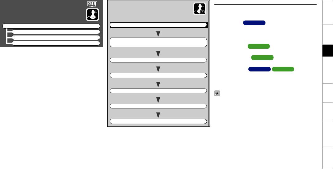
F Menu tree F
Auto Setup
a Auto Setup s Option
d Parameter Check
aAuto Setup
The settings are performed automatically.
GAuto Setup flowH
STEP1 |
Preparation |
vpage 14, 15 |
|
|
|
|
|
|
|
|
|
|
|
|
|
STEP2 |
Detection & Measurement (main) |
|
|
|
|
|
vpage 16, 17 |
|
|
|
|
|
|
|
|
|
|
|
|
|
|
|
|
STEP3 |
Measurement (2nd – 8th) |
vpage 18 |
|
|
|
|
|
|
|
|
|
|
|
|
|
STEP4 |
Calculation |
vpage 18 |
|
|
|
|
|
|
|
|
|
|
|
|
|
STEP5 |
Check |
vpage 19 |
|
|
|
|
|
|
|
|
|
|
|
|
|
STEP6 |
Store |
vpage 19 |
|
|
|
|
|
|
|
|
|
|
|
|
|
Finish |
|
|
vpage 20 |
|
|
|
|
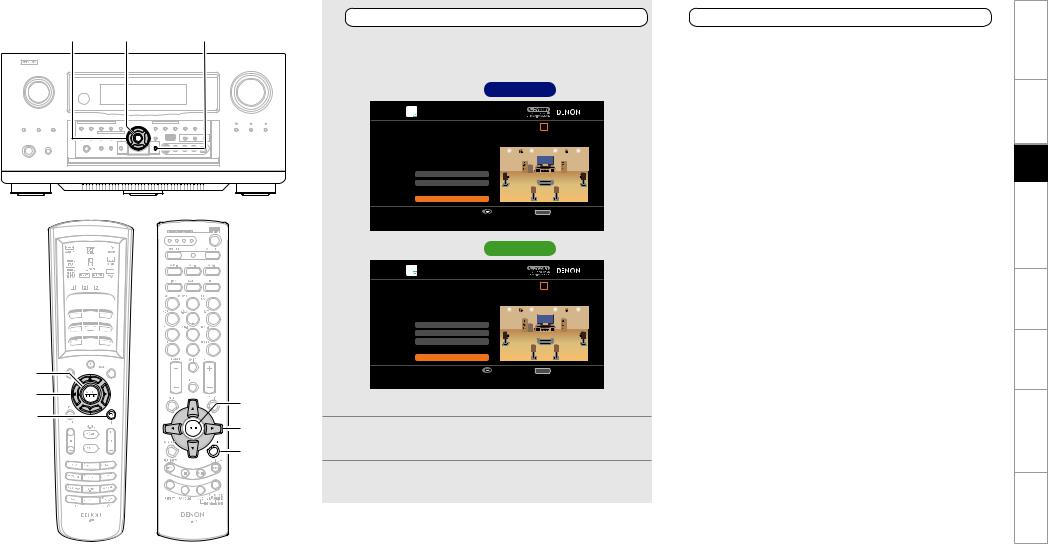
STEP1 Preparation
•Configure the following settings as required.
•To start Auto Setup without configuring the following settings, perform step 4 only, and then proceed to step 2.
n Amp Assign AVC-A1HD
Select the method for using the power amplifier in accordance with the connected speaker configuration.
Choose this when “Amp Assign” in the GUI menu is set to anything other than “Normal”.
n Pre-out Assign AVP-A1HD
Change the pre-out terminal assignment.
n XLR Out Polarity AVP-A1HD
Set to switch the XLR pre-out terminal polarity.
n Channel Select AVC-A1HD |
AVP-A1HD |
The measurement time can be shortened by selecting the speakers to be measured in advance. Please set if necessary.
When measuring 2 or 3 subwoofers, configure the “Channel Select” settings.
•“Front Height” is displayed when the “Amp Assign” – “Assign Mode” setting (vpage 28) in the GUI menu and the “Extension Channel” setting (vpage 28, 29) are set to “Front Height”.
•“Front Wide” is displayed when the “Amp Assign” – “Assign Mode” setting (vpage 28) in the GUI menu and the “Extension Channel” setting (vpage 28, 29) are set to “Front Wide”.
Specifications Troubleshooting Information Zone-Multi Operations Other Setup Connections Started Getting
14
uiop ENTER |
RETURN |
ENTER |
|
|
uio p |
ENTER |
|
RETURN |
||
uio p |
||
|
||
|
RETURN |
1 |
|
|
4 |
|
Configuring Various Settings |
|
Start Auto Setup |
||
|
|
|
||
Use ui to select the item you want to set, and then |
Use ui to select “Auto Setup Start” and then press |
|||
press ENTER. |
|
ENTER. |
||
The menu screen of the selected setting is displayed. |
|
Proceed to “STEP2 Detection & Measurement (main)” (vpage |
||
|
GSetup screen AVC-A1HD H |
|
16). |
|
|
|
|
|
|
|
|
|
|
|
AUTO SETUP |
STEP1 Preparation |
1 2 3 4 5 6 |
Connect the speakers and place them according |
|
to the recommendations in the manual. |
|
Set the following items |
|
if necessary. |
|
Amp Assign |
|
Channel Select |
|
Auto Setup Start |
|
Enter |
RETURN Cancel |
Start Auto Setup |
|
GSetup screen AVP-A1HD H
AUTO SETUP |
STEP1 Preparation |
1 2 3 4 5 6 |
Connect the speakers and place them according |
|
to the recommendations in the manual. |
|
Set the following items |
|
if necessary. |
|
Pre-out Assign |
|
XLR Out Polarity |
|
Channel Select |
|
Auto Setup Start |
|
Enter |
RETURN Cancel |
Start Auto Setup |
|
b For details of the items that can be set, see page 28 ~ 30.
2Press uio p to set.
3Press RETURN to return to the previous screen.
(Main remote control unit) |
(Sub remote control unit) |
15
Specifications Troubleshooting Information Zone-Multi Operations Other Setup Connections Started Getting

STEP2 Detection & Measurement (main)
i |
ENTER |
•In STEP 2, the subwoofer volume level and main listening position volume are measured.
•This step automatically checks the speaker configuration and speaker size, and calculates the channel level, distance, and crossover frequency. It also corrects distortion in the listening area.
•Install the supplied setup microphone to the main listening position.
1Measuring the subwoofer volume level
Select “Measure” and then press ENTER.
Measure the subwoofer volume level.
b When “Channel Select” – “Subwoofer” in the GUI menu is set to “Skip”, the subwoofer volume level is not measured.
b When 2 or 3 subwoofers are used, measure the volume level of each.
bAfter measuring the volume level of the subwoofer, if the following error message is displayed, adjust the subwoofer volume level using “Adjusting the subwoofer volume level” (vpage 17).
AUTO SETUP |
Caution! |
1 2 3 4 5 6 |
The subwoofer's level is too high or low. Please select "SW Level Matching" and adjust the level of your subwoofer unit. If you do not want to use the 
 subwoofer, select "Skip".


ENTER |
|
i |
ENTER |
|
i |
(Main remote control unit) |
(Sub remote control unit) |
SW Level Matching
Skip
|
|
|
Enter |
RETURN Cancel |
|
|
|
|
Proceed to subwoofer volume adjustment item |
|
|
|
|
|
|
||
2 |
|
|
|
||
|
|
Perform measurement of the |
|||
|
|
main listening position |
|||
When |
the subwoofer volume |
level measurement |
|||
is completely, the connected speakers are detected automatically.
b The measuring channel changes depending on the setting of “STEP1 Preparation” (vpage 14).
b It takes a few minutes for speaker measurement to complete.
3The detected speakers are displayed.
b The illustration below shows an example of when the front speakers, center speaker, subwoofer, surround speakers, surround back speakers and front height speakers have been detected.
AUTO SETUP |
STEP2 Speaker Detection Check |
1 2 3 4 5 6 |
|
||||||
Front |
Yes |
|
|
|
|
|||
Center |
Yes |
|
|
|
|
|||
Subwoofer |
1 spkr |
|
|
|
|
|
|
|
Surround |
Yes |
|
|
|
|
|
|
|
Surr. Back |
2 spkrs |
|
|
|
|
|
|
|
Front Height |
Yes |
|
|
|
|
|
|
|
|
|
|
|
|
|
|
|
|
Retry
Next→Measurement
 Enter RETURN Cancel
Proceed to STEP 3 after checking speaker connection result
b If a connected speaker is not displayed, the speaker may not be connected correctly. Check the speaker connection.
b To re-measure, press i to select “Retry”, and press ENTER.
4Use i to select “Next  Measurement” and then press ENTER.
Proceed to “STEP3 Measurement (2nd – 8th)” (vpage 18).
NOTE
If “Caution ” is displayed on the television screen, see “Error messages” (vpage 21). Check the related items, and implement the necessary measures. After resolving the error, perform Auto Setup again.
nWhen measuring has stopped
Press ENTER.
Specifications Troubleshooting Information Zone-Multi Operations Other Setup Connections Started Getting
16

ENTER
nAdjusting the subwoofer volume level
The optimum subwoofer volume level is 75 dB.
During “Measuring the subwoofer volume level” (vpage 16), an error message is displayed when one level of subwoofers is outside the 72 to 78 dB range.
When using a subwoofer with built-in amplifier (active type), adjust the subwoofer volume so that the subwoofer level is within the 72 to 78 dB range.
3Adjust the subwoofer volume level of your subwoofer so that the level display is within the range of 72 to 78 dB.
AUTO SETUP |
SW Level Matching |
1 2 3 4 5 6 |
Please adjust the level of your active subwoofer unit so that the level indicates approx. 75dB
ENTER


 ENTER
ENTER
(Main remote control unit) |
(Sub remote control unit) |
When 2 or 3 subwoofers are used, adjust the volume level of each subwoofer so that their volume level will set between 72~78 dB.
1Select “SW Level Matching” and then press ENTER.
AUTO SETUP |
Caution! |
1 2 3 4 5 6 |
The subwoofer's level is too high or low. Please select "SW Level Matching" and adjust the level of your subwoofer unit. If you do not want to use the 
 subwoofer, select "Skip".


Stop
99.8dB
Enter
Change from red to blue when level matches
b If the measured level is outside the 72 to 78 dB range, the level indicator is red.
b When measuring stops, press ENTER.
AUTO SETUP |
SW Level Matching |
1 2 3 4 5 6 |
Please adjust the level of your active subwoofer unit so that the level indicates approx. 75dB
SW Level Matching |
Stop |
Skip |
Enter |
RETURN Cancel |
75.5dB |
Proceed to subwoofer volume adjustment item
2 |
|
Enter |
|
Select “SW Test Start” and then press ENTER. |
Change from red to blue when level matches |
||
|
|||
Measure the subwoofer volume level. |
b If the measured level is within the 72 to 78 dB range, the level |
||
During measuring, a “Testing…” message is displayed. |
|||
|
indicator is blue. |
||
|
When measurements are completed, the measurement level |
|
|
|
value is displayed. |
When the measured level is within the 72 to 78 dB |
|
|
AUTO SETUP |
4range, press ENTER. |
SW Level Matching |
1 2 3 4 5 6 |
5 |
Select “Next” and then press ENTER. |
|
|||
Please place the microphone at ear height at main |
|
||
listening position, then push ENTER. |
|
|
Proceed to step 2 of “STEP2 Detection & Measurement |
|
|
|
|
(main)“(vpage 16).
SW Test Start
dB |
AUTO SETUP |
Next |
|
SW Level Matching |
1 2 3 4 5 6 |
Enter |
RETURN Cancel |
After adjustment, push "Next". |
|
Start measurement. Output test tone from subwoofer |
|
|
|
|
|
SW Test Start |
|
|
|
dB |
|
|
|
Next |
|
|
|
Enter |
RETURN Cancel |
|
|
Proceed to next measurement |
|
Specifications Troubleshooting Information Zone-Multi Operations Other Setup Connections Started Getting
17

ENTER ui
STEP3 Measurement (2nd – 8th)
•In STEP 3, you will perform measurements at multiple positions (two to eight positions) other than the main listening position. Measurements can be made in up to eight positions.
•You can achieve a more effective correction of distortion within the listening area by performing measurements at multiple positions.
•Move the provided set up microphone to the measurement point.
1Move the setup microphone to position 2, use ui to select “Measure”, and then press ENTER.
The measurement of the second position starts.
AUTO SETUP |
STEP3 Measurement (2nd) |
1 2 3 4 5 6 |
Please place the microphone at ear height at 2nd listening position.
|
|
|
Measure |
|
|
|
|
Next→Calculation |
|
|
|
|
Enter |
RETURN Cancel |
|
|
|
Start measurement. Output large test tone during measuring |
|
|
|
b To omit measurements from the 2nd position onwards, press i, |
||
|
|
select “Next |
Calculation” and press ENTER. Proceed to “STEP4 |
|
|
|
Calculation”. |
|
|
u |
|
Repeat step 1, measuring positions 3 to 8. |
||
|
2Whenmeasurementofposition8iscompleted,a“Measurements |
|||
ENTER |
u |
finished.” message is displayed. |
|
|
i |
b To re-measure, press i to select “Retry”, and press ENTER. Re- |
|||
ENTER |
measure the previous point. |
|
||
|
|
|
|
|
|
i |
|
AUTO SETUP |
|
|
|
|
|
|
|
|
STEP3 Measurement (Finish) |
1 2 3 4 5 6 |
|
|
Measurements finished. |
|
|
|
Retry |
|
|
|
Next→Calculation |
|
(Main remote control unit) |
(Sub remote control unit) |
Enter |
RETURN Cancel |
Proceed to STEP 4 (Calculation) |
|
3Use i to select “Next Calculation” and then press
ENTER.
Proceed to “STEP4 Calculation” (vpage 18).
NOTE
If “Caution ” is displayed on the television screen, see “Error messages” (vpage 21). Check the related items, and implement the necessary measures. After resolving the error, perform Auto Setup again.
nWhen measuring has stopped
Press ENTER.
STEP4 Calculation
In STEP 4, the measured results from STEP 2 and STEP 3 are analyzed.
When the measurements are completed, press i to select
“Next Calculation”, and press ENTER.
The measured results from STEP 2 and STEP 3 are automatically analyzed, and the frequency response of each speaker in the listening room is determined.
AUTO SETUP |
STEP4 Calculation |
1 2 3 4 5 6 |
Now calculating…Please wait. |
|
20% |
b It takes a few minutes for analysis to complete. The time required for this analysis depends on the number of speakers connected. The more connected speakers there are, the longer it takes to perform analysis.
Specifications Troubleshooting Information Zone-Multi Operations Other Setup Connections Started Getting
18

uio ENTER RETURN
ENTER |
|
|
uio |
ENTER |
|
RETURN |
||
uio |
||
|
||
|
RETURN |
(Main remote control unit) |
(Sub remote control unit) |
STEP5 Check |
STEP6 Store |
|
|
|
|
In STEP 5, the results of the analysis from STEP 4 are confirmed. |
In STEP 6, the measured results from STEP 2 and STEP 3 are saved. |
|
Use ui to select the item you want to check, and |
|
Select “Store” and then press ENTER. |
1then press ENTER. |
|
Save the measurement results. |
AUTO SETUP |
|
AUTO SETUP |
|
STEP5 Check |
1 2 3 4 5 6 |
STEP6 Store |
1 2 3 4 5 6 |
Check processing results. |
Press "Store" to store calculation results. |
To proceed, press "Next". |
|
Spkr Config Chck |
|
|
|
|
|
Distance Check |
|
|
|
|
|
Ch. Level Check |
|
|
Store |
|
|
Crossover Check |
|
|
|
|
|
Next→Store |
|
|
|
|
|
Enter |
RETURN |
Cancel |
Enter |
RETURN |
Cancel |
Proceed to STEP 6 (Store) |
|
|
Apply and store measurement result |
|
|
b A value that is different to the measured distance may be set.
b To check other items, press RETURN and select the item that you want to check.
2Use i to select “Next  Store” and then press
ENTER.
Proceed to “STEP6 Store” (vpage 19).
AUTO SETUP |
STEP6 Store |
1 2 3 4 5 6 |
Now storing…Please wait. |
|
20% |
NOTE
•If the result differs from the actual connection status, or if “Caution!” is displayed, see “Error messages” (vpage 21). Check the related items, and implement the necessary measures. After resolving the error, perform Auto Setup again.
•If the result still differs from the actual connection status after remeasurement or the error message still appears, it is possible that the speakers are not connected properly. Turn this unit off, check the speaker connections and repeat the measurement process from the beginning.
•If you change speaker positions or orientation, perform Auto Setup again to find the optimal equalizer settings.
b It takes approximately 20 seconds to finish saving the results.
b If the measuring results are not to be saved, press RETURN. A message “Cancel auto setup?” will be displayed. Press o then select “Yes”. All the measured Auto Setup data will be erased.
NOTE
During saving of measurement results, be sure not to turn off the power.
Specifications Troubleshooting Information Zone-Multi Operations Other Setup Connections Started Getting
19
ENTER ui
u |
|
|
ENTER |
u |
|
i |
||
ENTER |
||
|
||
|
i |
(Main remote control unit) |
(Sub remote control unit) |
Finish
Auto Setup is complete.
1Unplug the setup microphone from the unit’s SETUP MIC jack.
2 |
Set Audyssey Dynamic Volume®. |
|
|
|
AUTO SETUP |
|
|
|
|
|
|
|
|
Finish |
1 2 3 4 5 6 |
Storing complete.
Auto Setup is now finished.
Please unplug microphone.
Turn on Dynamic Volume ?
Yes
No
Exit
Turn Dynamic Volume off and exit Auto Setup
b This feature adjusts the output volume to the optimal level while constantly monitoring the level of the audio input to the unit. Optimal volume control is performed automatically without any loss in the dynamism and clarity of the sound when, for example, the volume suddenly increases for commercials shown during television programs.
nWhen turning Dynamic Volume® on
Use u to select “Yes”, and then press ENTER. The unit automatically enters “Evening” mode.
nWhen turning Dynamic Volume® off
Use i to select “No”, and then press ENTER.
NOTE
•After performing Auto Setup, do not change the speaker connections or subwoofer volume. In event of a change, perform Auto Setup again.
•After performing Auto Setup with two or three subwoofers, do not change the channel distances and levels of any of the subwoofers.
Specifications Troubleshooting Information Zone-Multi Operations Other Setup Connections Started Getting
20

Error messages
NOTE
•An error message is displayed if Auto Setup could not be completed due to speaker placement, the measurement environment, etc. Check the related items, and implement the necessary measures. After resolving the error, perform Auto Setup again.
•If the result still differs from the actual connection status after remeasurement or the error message still appears, it is possible that the speakers are not connected properly. Turn this unit off, check the speaker connections and repeat the measurement process from the beginning.
•Be sure to turn off the power before checking speaker connections.
Examples |
Error details |
Measures |
AUTO SETUP |
|
• Correct measurement is not possible due to inappropriate subwoofer |
• When using a subwoofer with built-in amplifier (active type), use |
Caution! |
1 2 3 4 5 6 |
volume. |
“SW Level Matching” to adjust the subwoofer volume (vpage 17 |
The subwoofer's level is too high or low. Please select "SW |
|
“Adjusting the subwoofer volume level”). |
|
Level Matching" and adjust the level of your subwoofer unit. |
|
||
If you do not want to use the |
|
• When using a subwoofer without a built-in amplifier, select “Skip”, |
|
subwoofer, select "Skip". |
|
||
|
|
|
and then press ENTER. |
SW Level Matching |
|
|
|
Skip |
|
|
|
AUTO SETUP |
|
• The connected setup microphone is broken, or a device other than |
• Connect the included setup microphone to the SETUP MIC jack of |
|
Caution! |
the supplied setup microphone is connected. |
this unit. |
No microphone or speaker |
• Not all speakers could be detected. |
• Check the speaker connections. |
|
|
|
• The front L speaker was not properly detected. |
|
|
Retry |
|
|
AUTO SETUP |
|
• There is too much noise in the room for accurate measurements to |
• Either turn off any device generating noise or move it away. |
|
Caution! |
be made. |
• Perform again when the surroundings are quieter. |
Ambient noise is too high |
• Speaker or subwoofer sound is too low for accurate measurements |
• Check the speaker installation and the direction in which the speakers |
|
|
or Level is too low |
to be made. |
are facing. |
|
|
||
|
|
|
• Adjust the subwoofer’s volume. |
|
Retry |
|
|
AUTO SETUP |
|
• The displayed speaker could not be detected. |
• Check the connections of the displayed speaker. |
Caution! |
1 2 3 4 5 6 |
(The screen on the left indicates that the front right speaker cannot |
|
Front R |
None |
be detected.) |
|
Retry |
|
|
|
AUTO SETUP |
|
• The displayed speaker is connected with the polarity reversed. |
• Check the polarity of the displayed speaker. |
Caution! |
1 2 3 4 5 6 |
(The screen on the left indicates that the polarity phases of the front |
• For some speakers, this error message may be displayed even if |
Front R |
Phase |
right speakers are reversed.) |
the speaker is properly connected. If you are sure the connection is |
|
|
|
correct, press ui to select “Skip”, then press ENTER. |
Retry |
|
|
|
Skip |
|
|
|
Specifications Troubleshooting Information Zone-Multi Operations Other Setup Connections Started Getting
21
sOption
Make direct mode settings.
Direct Mode
Select MultEQ® XT 32 use for DIRECT or PURE DIRECT mode.
[Selectable items] |
ON |
|
OFF |
|
|
|
|
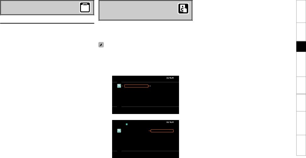
dParameter Check
Check Auto Setup measurement results.
This is displayed after the Auto Setup procedure is completed.
[Selectable items]
Spkr Config Check |
|
Distance Check |
|
Ch. Level Check |
|||||
|
|
|
|
|
|
||||
Crossover Check |
|
|
EQ Check |
|
Restore |
|
|||
•If “EQ Check” is selected, press ui to select equalizing curve
(“Audyssey” or “Audyssey Flat”) to be checked, and then press
ENTER or p.
Use ui to switch the display between the different speakers.
•If “Restore” is selected, all settings are returned to the Auto Setup results (values initially calculated by MultEQ® XT 32) even if each setting was changed manually.
 PARAMETER CHECK
Restore |
Yes |
Spkr Config Check |
No |
Distance Check |
|
Ch.Level Check |
|
Crossover Check |
|
EQ Check |
|
Restore auto setup measurement result
|
|
RESTORE |
|
Restore |
Yes |
|
No |
 Enter
Enter
Restore auto setup measurement result
Specifications Troubleshooting Information Zone-Multi Operations Other Setup Connections Started Getting
22
Loading...