


AV SURROUND RECEIVER RÉCEPTEUR AUDIO-VIDÉO
AVR-1604/684
OPERATING INSTRUCTIONS MODE D’EMPLOI
|
|
|
|
|
|
|
|
|
|
|
|
|
|
|
|
|
|
|
|
|
|
|
|
|
|
|
|
|
|
|
|
|
|
|
|
FOR ENGLISH READERS |
PAGE 2 ~ PAGE 62, 122 ~ 126 |
||||||||||
2We greatly appreciate your purchase of this unit.
2To be sure you take maximum advantage of all the features this unit has to offer, read these instructions carefully and use the set properly. Be sure to keep this manual for future reference should any questions or problems arise.
“SERIAL NO.
PLEASE RECORD UNIT SERIAL NUMBER ATTACHED TO THE REAR OF THE CABINET FOR FUTURE REFERENCE”
POUR LES LECTEURS FRANCAIS PAGE 2, 63 ~ PAGE 126
2Nous vous remercions pour l’achat de cet appareil.
2Pour être sûr de profiter au maximum de toutes les caractéristiques qu’offre cet appareil, lire avec soin ces instructions et bien utiliser l’appareil. Toujours conserver ce mode d’emploi pour s’y référer ultérieurement en cas de question ou de problème.
“NO. DE SERIE
PRIERE DE NOTER LE NUMERO DE SERIE DE L’APPAREIL INSCRIT A L’ARRIERE DU COFFRET DE FAÇON A POUVOIR LE CONSULTER EN CAS DE PROBLEME.”
ENGLISH FRANCAIS
2SAFETY PRECAUTIONS
CAUTION
RISK OF ELECTRIC SHOCK
DO NOT OPEN
CAUTION: TO REDUCE THE RISK OF ELECTRIC SHOCK, DO NOT REMOVE COVER (OR BACK). NO USER-SERVICEABLE PARTS INSIDE. REFER SERVICING TO QUALIFIED SERVICE PERSONNEL.
The lightning flash with arrowhead symbol, within an equilateral triangle, is intended to alert the user to the presence of uninsulated “dangerous voltage” within the product’s enclosure that may be of sufficient magnitude to constitute a risk of electric shock to persons.
The exclamation point within an equilateral triangle is intended to alert the user to the presence of important operating and maintenance (servicing) instructions in the literature accompanying the appliance.
WARNING: TO REDUCE THE RISK OF FIRE OR ELECTRIC SHOCK, DO NOT EXPOSE THIS APPLIANCE TO RAIN OR MOISTURE.
• FOR CANADA MODEL ONLY
CAUTION
TO PREVENT ELECTRIC SHOCK, MATCH WIDE BLADE OF PLUG TO WIDE SLOT, FULLY INSERT.
• POUR LES MODELE CANADIEN UNIQUEMENT
ATTENTION
POUR ÉVITER LES CHOCS ÉLECTRIQUES, INTERODUIRE LA LAME LA PLUS LARGE DE LA FICHE DANS LA BORNE CORRESPONDANTE DE LA PRISE ET POUSSER JUSQU’ AU FOND.
This device complies with Part 15 of the FCC Rules. Operation is subject to the following two conditions: (1) This device may not cause harmful interference, and (2) this device must accept any interference received, including interference that may cause undesired operation.
This Class B digital apparatus meets all requirements of the Canadian Interference-Causing Equipment Regulations.
Cet appareil numérique de la classe B respecte toutes les exigences du Règlement sur le matériel brouilleur du Canada.
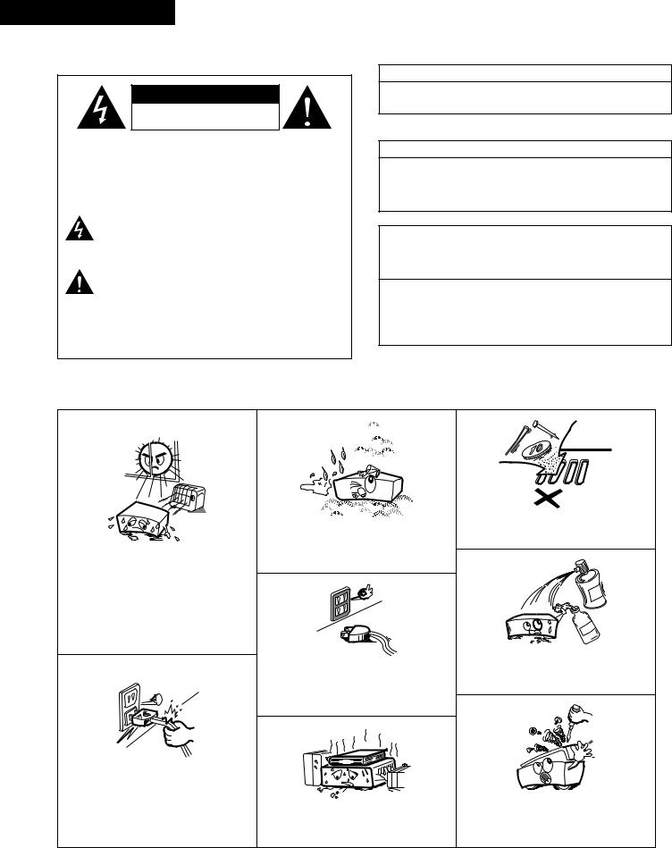
2NOTE ON USE / OBSERVATIONS RELATIVES A L’UTILISATION
•Avoid high temperatures.
Allow for sufficient heat dispersion when installed on a rack.
•Eviter des températures élevées.
Tenir compte d’une dispersion de chaleur suffisante lors de l’installation sur une étagère.
•Handle the power cord carefully.
Hold the plug when unplugging the cord.
•Manipuler le cordon d’alimentation avec précaution.
Tenir la prise lors du débranchement du cordon.
•Keep the set free from moisture, water, and dust.
•Protéger l’appareil contre l’humidité, l’eau et la poussière.
•Unplug the power cord when not using the set for long periods of time.
•Débrancher le cordon d’alimentation lorsque l’appareil n’est pas utilisé pendant de longues périodes.
*(For sets with ventilation holes)
•Do not obstruct the ventilation holes.
•Ne pas obstruer les trous d’aération.
•Do not let foreign objects in the set.
•Ne pas laisser des objets étrangers dans l’appareil.
•Do not let insecticides, benzene, and thinner come in contact with the set.
•Ne pas mettre en contact des insecticides, du benzène et un diluant avec l’appareil.
•Never disassemble or modify the set in any way.
•Ne jamais démonter ou modifier l’appareil d’une manière ou d’une autre.
2
SAFETY INSTRUCTIONS
1.Read Instructions – All the safety and operating instructions should be read before the product is operated.
2.Retain Instructions – The safety and operating instructions should be retained for future reference.
3.Heed Warnings – All warnings on the product and in the operating instructions should be adhered to.
4.Follow Instructions – All operating and use instructions should be followed.
5.Cleaning – Unplug this product from the wall outlet before cleaning. Do not use liquid cleaners or aerosol cleaners.
6.Attachments – Do not use attachments not recommended by the product manufacturer as they may cause hazards.
7.Water and Moisture – Do not use this product near water – for example, near a bath tub, wash bowl, kitchen sink, or laundry tub; in a wet basement; or near a swimming pool; and the like.
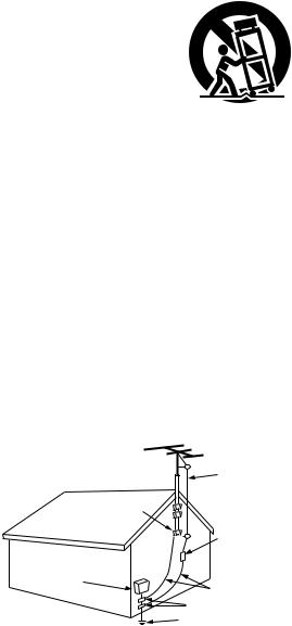
8.Accessories – Do not place this product on an unstable cart, stand, tripod, bracket, or table. The product may fall, causing serious injury to a child or adult, and serious damage to the product. Use only with a cart, stand, tripod, bracket, or table recommended by the manufacturer, or sold with the product. Any mounting of the product should follow the manufacturer’s instructions, and should use a
mounting accessory recommended by the
manufacturer.
9. A product and cart combination should be moved with care. Quick stops, excessive force, and uneven surfaces may cause the product and cart combination to overturn.
10.Ventilation – Slots and openings in the cabinet are provided for ventilation and to ensure reliable operation of the product and to protect it from overheating, and these openings must not be blocked or covered. The openings should never be blocked by placing the product on a bed, sofa, rug, or other similar surface. This product should not be placed in a built-in installation such as a bookcase or rack unless proper ventilation is provided or the manufacturer’s instructions have been adhered to.
11.Power Sources – This product should be operated only from the type of power source indicated on the marking label. If you are not sure of the type of power supply to your home, consult your product dealer or local power company. For products intended to operate from battery power, or other sources, refer to the operating instructions.
12.Grounding or Polarization – This product may be equipped with a polarized alternating-current line plug (a plug having one blade wider than the other). This plug will fit into the power outlet only one way. This is a safety feature. If you are unable to insert the plug fully into the outlet, try reversing the plug. If the plug should still fail to fit, contact your electrician to replace your obsolete outlet. Do not defeat the safety purpose of the polarized plug.
FIGURE A
EXAMPLE OF ANTENNA GROUNDING
AS PER NATIONAL
ELECTRICAL CODE ANTENNA
LEAD IN
WIRE
GROUND
CLAMP
ANTENNA DISCHARGE UNIT
(NEC SECTION 810-20)
ELECTRIC
SERVICE
EQUIPMENT
GROUNDING CONDUCTORS (NEC SECTION 810-21)
GROUND CLAMPS
POWER SERVICE GROUNDING
ELECTRODE SYSTEM (NEC ART 250, PART H)
NEC - NATIONAL ELECTRICAL CODE
13.Power-Cord Protection – Power-supply cords should be routed so that they are not likely to be walked on or pinched by items placed upon or against them, paying particular attention to cords at plugs, convenience receptacles, and the point where they exit from the product.
15.Outdoor Antenna Grounding – If an outside antenna or cable system is connected to the product, be sure the antenna or cable system is grounded so as to provide some protection against voltage surges and built-up static charges. Article 810 of the National Electrical Code, ANSI/NFPA 70, provides information with regard to proper grounding of the mast and supporting structure, grounding of the lead-in wire to an antenna discharge unit, size of grounding conductors, location of antenna-discharge unit, connection to grounding electrodes, and requirements for the grounding electrode. See Figure A.
16.Lightning – For added protection for this product during a lightning storm, or when it is left unattended and unused for long periods of time, unplug it from the wall outlet and disconnect the antenna or cable system. This will prevent damage to the product due to lightning and power-line surges.
17.Power Lines – An outside antenna system should not be located in the vicinity of overhead power lines or other electric light or power circuits, or where it can fall into such power lines or circuits. When installing an outside antenna system, extreme care should be taken to keep from touching such power lines or circuits as contact with them might be fatal.
18.Overloading – Do not overload wall outlets, extension cords, or integral convenience receptacles as this can result in a risk of fire or electric shock.
19.Object and Liquid Entry – Never push objects of any kind into this product through openings as they may touch dangerous voltage points or short-out parts that could result in a fire or electric shock. Never spill liquid of any kind on the product.
20.Servicing – Do not attempt to service this product yourself as opening or removing covers may expose you to dangerous voltage or other hazards. Refer all servicing to qualified service personnel.
21.Damage Requiring Service – Unplug this product from the wall outlet and refer servicing to qualified service personnel under the following conditions:
a)When the power-supply cord or plug is damaged,
b)If liquid has been spilled, or objects have fallen into the product,
c)If the product has been exposed to rain or water,
d)If the product does not operate normally by following the operating instructions. Adjust only those controls that are covered by the operating instructions as an improper adjustment of other controls may result in damage and will often require extensive work by a qualified technician to restore the product to its normal operation,
e)If the product has been dropped or damaged in any way, and
f)When the product exhibits a distinct change in performance
– this indicates a need for service.
22.Replacement Parts – When replacement parts are required, be sure the service technician has used replacement parts specified by the manufacturer or have the same characteristics as the original part. Unauthorized substitutions may result in fire, electric shock, or other hazards.
23.Safety Check – Upon completion of any service or repairs to this product, ask the service technician to perform safety checks to determine that the product is in proper operating condition.
24.Wall or Ceiling Mounting – The product should be mounted to a wall or ceiling only as recommended by the manufacturer.
25.Heat – The product should be situated away from heat sources such as radiators, heat registers, stoves, or other products (including amplifiers) that produce heat.
3
ENGLISH
2INTRODUCTION
Thank you for choosing the DENON A/V Surround receiver. This remarkable component has been engineered to provide superb surround sound listening with home theater sources such as DVD, as well as providing outstanding high fidelity reproduction of your favorite music sources.
As this product is provided with an immense array of features, we recommend that before you begin hookup and operation that you review the contents of this manual before proceeding.
TABLE OF CONTENTS
z Before Using .............................................................................................. |
4 |
x Cautions on Installation .............................................................................. |
5 |
c Cautions on Handling ................................................................................. |
5 |
v Features...................................................................................................... |
5 |
b Part Names and Functions ..................................................................... |
6, 7 |
n Read this first ............................................................................................. |
8 |
m Setting up the Speaker Systems................................................................ |
8 |
, Connections ......................................................................................... |
9~15 |
. Using the Remote Control Unit................................................................ |
16 |
⁄0Setting up the System ....................................................................... |
17~26 |
⁄1Remote Control Unit .......................................................................... |
27~31 |
⁄2Operation ........................................................................................... |
32~36 |
⁄3Surround............................................................................................. |
37~45 |
⁄4DSP Surround Simulation................................................................... |
46~50 |
⁄5Listening to the Radio ……………………………………………………51~53 |
|
⁄6Last Function Memory ............................................................................. |
54 |
⁄7Initialization of the Microprocessor.…………………………………………54 |
|
⁄8Additional Information........................................................................ |
55~60 |
⁄9Troubleshooting ........................................................................................ |
61 |
¤0Specifications .…………………………………………………………………62 |
|
List of Preset Codes.............................................................................. |
122~126 |
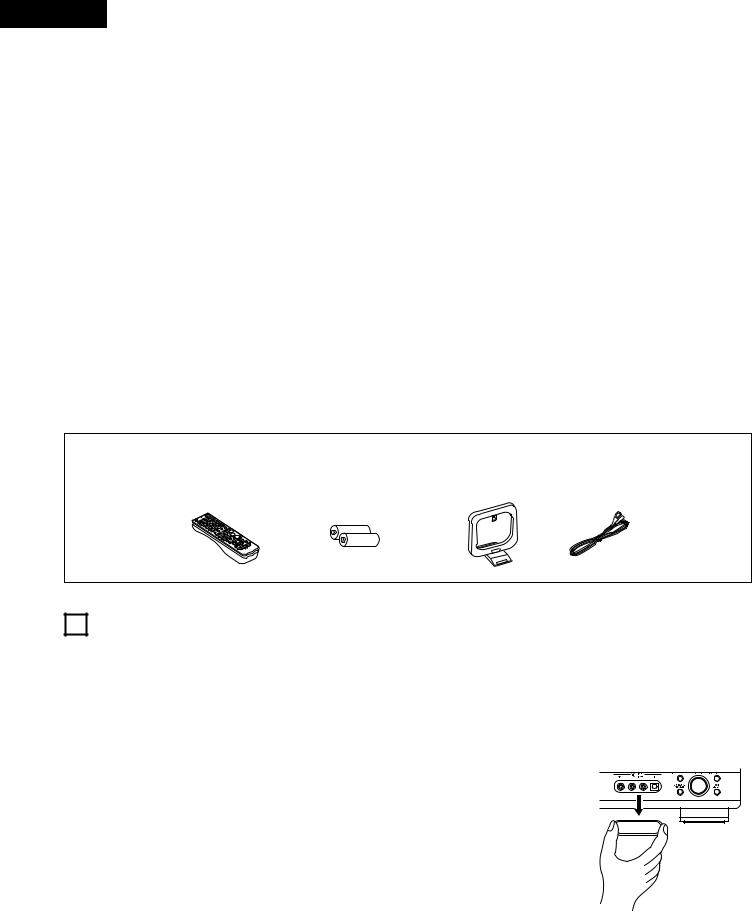
2ACCESSORIES
Check that the following parts are included in addition to the main unit:
q Operating instructions ............................................................................ |
1 |
w Warranty ................................................................................................. |
1 |
e Service station list................................................................................... |
1 |
r Remote control unit (RC-941) ................................................................. |
1 |
t R6P/AA batteries .................................................................................... |
2 |
y AM loop antenna .................................................................................... |
1 |
u FM indoor antenna.................................................................................. |
1 |
r |
t |
y |
u |
1 BEFORE USING
Pay attention to the following before using this unit:
•Moving the set
To prevent short circuits or damaged wires in the connection cords, always unplug the power cord and disconnect the connection cords between all other audio components when moving the set.
•Before turning the power operation switch on
Check once again that all connections are proper and that there are not problems with the connection cords. Always set the power operation switch to the standby position before connecting and disconnecting connection cords.
•Store this instructions in a safe place.
After reading, store this instructions along with the warranty in a safe place.
•Note that the illustrations in this instructions may differ from the actual set for explanation purposes.
•V. AUX terminal
The AVR-1604/684’s front panel is equipped with a V. AUX terminal. Remove the cap covering the terminal when you want to use it.
4
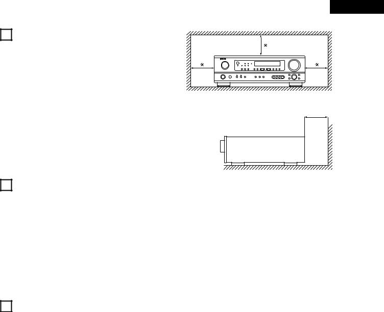
2 CAUTIONS ON INSTALLATION
Noise or disturbance of the picture may be generated if this unit or any other electronic equipment using microprocessors is used near a tuner or TV.
If this happens, take the following steps:
•Install this unit as far as possible from the tuner or TV.
•Set the antenna wires from the tuner or TV away from this unit’s power cord and input/output connection cords.
•Noise or disturbance tends to occur particularly when using indoor antennas or 300 Ω /ohms feeder wires. We recommend using outdoor antennas and 75 Ω /ohms coaxial cables.
For heat dispersal, leave at least 0.3 ft (10 cm) of space between the top, back and sides of this unit and the wall or other components.
ENGLISH
0.3 ft (10 cm) or more |
0.3 ft (10 cm) or more
wall
3CAUTIONS ON HANDLING
•Switching the input function when input jacks are not connected
A clicking noise may be produced if the input function is switched when nothing is connected to the input jacks. If this happens, either turn down the MASTER VOLUME control or connect components to the input jacks.
•Muting of PRE OUT jack, HEADPHONE jack and SPEAKER terminals
The PRE OUT jack, HEADPHONE jack and SPEAKER terminals include a muting circuit. Because of this, the output signals are greatly reduced for several seconds after the power operation switch is turned on or input function, surround mode or any other set-up is changed.
If the volume is turned up during this time, the output will be very high after the muting circuit stops functioning. Always wait until the muting circuit turns off before adjusting the volume.
•Whenever the power operation switch is in the STANDBY state, the apparatus is still connected on some AC line voltages.
Please be sure to unplug the cord when you leave home for, say, a vacation.
4FEATURES
1.Dolby Digital EX decoder system
Dolby Digital EX is a 6.1-channel surround format proposed by Dolby Laboratories that allows users to enjoy in their homes the “DOLBY DIGITAL SURROUND EX” audio format jointly developed by Dolby Laboratories and Lucas Films and first used for the movie “Star Wars Episode 1 – Phantom Menace”.
The 6.1 channels of sound, including surround back channels, provide improved sound positioning and expression of space.
2.DTS-ES Extended Surround and DTS Neo:6
The AVR-1604/684 is compatible with DTS-ES Extended Surround, a new multi-channel format developed by Digital Theater Systems Inc. The AVR-1604/684 is also compatible with DTS Neo:6, a surround mode allowing 6.1-channel playback of regular stereo sources.
3.Dolby Pro Logic II decoder
Dolby Pro Logic II is a new format for playing multichannel audio signals that offers improvements over conventional Dolby Pro Logic. It can be used to decode not only sources recorded in Dolby Surround but also regular stereo sources into five channels (front left/right, center and surround left/right). In addition, various parameters can be set according to the type of source and the contents, so you can adjust the sound field with greater precision.
4.Dolby Digital decoder
Using advanced digital processing algorithms, Dolby Digital provides up to 5.1 channels of wide-range, high fidelity surround sound. Dolby Digital is the default digital audio delivery system for DVD and North American DTV.
5.DTS (Digital Theater Systems)
DTS provides up to 5.1 channels of wide-range, high fidelity surround sound, from sources such as laser disc, DVD and specially-encoded music discs.
6.Auto Surround Mode
This function stores the surround mode last used for an input signal in the memory and automatically sets that surround mode the next time that signal is input.
7.6CH EXT. IN jacks
This unit is equipped with 6CH EXT. IN jacks for use with audio formats of the future.
8.High performance DSP simulates 7 sound fields
Playback is possible in 7 surround modes: 5/6-channel Stereo, Mono Movie, Rock Arena, Jazz Club, Video Game, Matrix and Virtual. You can enjoy a variety of sound effects for different movie scenes and program sources even with stereo sources not in Dolby Surround.
9.Personal Memory Plus function
Personal Memory Plus is an advanced version of Personal Memory. With Personal Memory Plus, the set automatically memorizes the surround mode, channel volume, surround parameters, etc., for each of the separate input sources.
5
ENGLISH
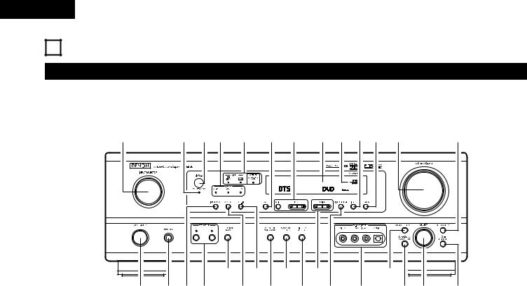
5 PART NAMES AND FUNCTIONS
Front Panel
• For details on the functions of these parts, refer to the pages given in parentheses ( ).
#0 |
@9@8@7 @6 @5 @4 @3@2@1@0 !9 |
!8 |
|
t |
u |
o |
!1 |
!4 |
|
q |
w e r |
y i |
|
!0 !2 !3 |
!5!6 |
!7 |
q Power operation switch .............................................. |
(18, 32, 51) |
w Headphones jack (PHONES).................................................... |
(35) |
e INPUT MODE button................................................... |
(33, 36, 43) |
r SPEAKER A/B buttons....................................................... |
(32, 54) |
t SURROUND BACK button ...................................................... |
(43) |
y ANALOG button ................................................................ |
(33, 36) |
u EXT. IN button ................................................................... |
(33, 36) |
i DOLBY/DTS SURROUND button ................................ |
(37, 39, 43) |
o 5CH/6CH STEREO button ................................................. |
(46, 49) |
!0DIRECT/STEREO button .......................................................... |
(46) |
!1TUNING D (up) / H (down) buttons ......................................... |
(52) |
!2VIDEO SELECT button ............................................................ |
(35) |
!3V. AUX terminals.................................................................. |
(4, 11) |
!4SURROUND MODE button ............................................... |
(34, 49) |
!5SURROUND PARAMETER button..................................... |
(39, 47) |
!6SELECT knob............................................................... |
(34, 39, 49) |
!7TONE DEFEAT button ............................................................. |
(34) |
!8TONE CONTROL button.......................................................... |
(34) |
!9MASTER VOLUME control...................................................... |
(34) |
@0STATUS button ........................................................................ |
(35) |
@1DIMMER button ...................................................................... |
(35) |
@2Master volume indicator (VOLUME LEVEL)............................ |
(34) |
@3Display |
|
@4Preset station select buttons ............................................ |
(51, 53) |
@5BAND button ........................................................................... |
(52) |
@6SIGNAL indicators.................................................................... |
(34) |
@7INPUT mode indicators............................................................ |
(34) |
@8Remote control sensor (REMOTE SENSOR) .......................... |
(16) |
@9Power operation indicator (ON/STANDBY) |
|
#0INPUT SELECTOR knob .......................................................... |
(33) |
6
ENGLISH
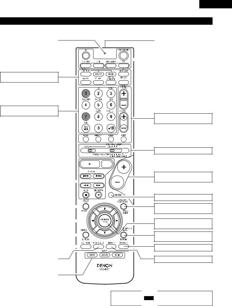
Remote control unit
• For details on the functions of these parts, refer to the pages given in parentheses ( ).
.............................LED (indicator) |
(28, 31) |
|
|
SURROUND |
|
buttons................................... |
(34, 37, 47) |
Input source selector |
|
buttons ............................ |
(28~31, 33, 39) |
|
|
|
|
|
|
|
|
|
|
|
|
|
|
|
|
|
|
|
|
|
|
|
|
|
|
|
System buttons |
(27, 29, 30) |
|
|
|
|
|
|
|
|
|
|
|
|
|
|
||
|
|
|
|
|
|
|
||
|
|
|
|
|
|
|
|
|
SYSTEM SET UP/ |
|
|
|
|
|
|
|
|
|
|
|
|
|
|
|
|
|
|
|
|
|
|
|
|
|
|
|
|
|
SETUP button |
(17, 26, 29) |
|
|
|
|
|
|
|
|
|
|
|
|
|
|
|
|
|
|
|
|
|
|
|
|
|
|
||
|
|
|
|
|
|
|
|
|
|
|
|
|
|
|
|
|
|
|
|
|
|
|
|
|
|
|
|
|
|
Cursor |
|
|
|
|
|
|
|
|
|
|
|
|
|
|
|
|
|
|
|
|
|
|
|
|
|
|
|
|
|
buttons |
(17, 29, 37, 47) |
|
|
|
|
|
|
|
|
|
|
|
|
|
|
|
|
|
|
|
|
|
|
|
|
|
|
||
|
|
|
|
|
|
|
|
|
|
|
|
|
|
|
|
|
|
|
|
|
|
|
|
|
|
|
|
|
|
STATUS/DISPLAY button |
(29, 35) |
|
|
|
|
|
|
|
|
|
|
|
|
|
|
|
|
|
|
|
|
|
|
|
|
|
|||
|
|
|
|
|
|
|
|
|
|
|
|
|
||
|
|
|
|
|
|
|
|
|
|
|
|
|
|
|
|
|
|
|
|
|
|
|
|
|
|
|
|
|
|
|
|
|
|
|
|
|
|
|
|
|
|
|
|
|
|
|
|
|
|
|
|
|
|
|
|
|
|
|
|
Test tone button |
(37) |
|
|
|
|
|
|
|
|
|
|
|
|
|
|
|
|
|
|
|
|
|
|
|
|
|
|
||
|
|
|
|
|
|
|
|
|
|
|
|
|
|
|
|
|
|
|
|
|
|
|
|
|
|
|
|
|
|
|
|
|
|
|
|
|
|
|
|
|
|
|
|
|
|
|
|
|
|
|
|
|
|
|
|
|
|
|
|
VIDEO SELECT button....................... |
(35) |
|
|
|
|
|
|
|
|
|
|
|
|
|
|
|
|
|
|
|
|
|
|
|
|
|
|
|
|
|
|
|
|
|
|
|
|
|
|
|
|
|
|
|
INPUT MODE selector |
|
|
|
|
|
|
|
|
|
|
|
|
|
|
|
|
|
|
|
|
|
|
|
|
|
|
|
|
|
buttons |
(33, 36) |
|
|
|
|
|
|
|
|
|
|
|
|
|
|
|
|
|
|
|
|
|
|
|
|
|
|
||
|
|
|
|
|
|
|
|
|
|
|
|
|
|
|
|
|
|
Remote control signal |
|
|
|
|
transmitter ......................................... |
(16) |
|
|
|
|
|
|
|
|
|
|
|
|
|
POWER buttons |
(18, 28~30, 32) |
|
|
|||
|
|
|
||
|
|
|
|
|
Tuner system/ |
|
System buttons ............... |
(27, 30, 52, 53) |
Mode selector switches..(17, 27~29, 31)
Master volume control |
|
buttons............................................... |
(34) |
MUTING button ................................. |
(35) |
SURROUND PARAMETER |
|
button........................................... |
(29, 39) |
CH SELECT (channel select)/ |
|
ENTER button.................. |
(17, 29, 38, 40) |
SURROUND BACK/ |
|
RETURN button ........................... |
(29, 43) |
SPEAKER select button ..................... |
(32) |
DIMMER button................................. |
(35) |
NOTE: |
|
• The shaded buttons |
do not function with the AVR-1604/684. |
(Nothing happens when they are pressed.)
7
ENGLISH
6 READ THIS FIRST
This AV Surround Receiver must be setup before use. Following these steps.
Step 1 (page 8 to 15)
Choose the best location to setup the Speakers and connecting the components.
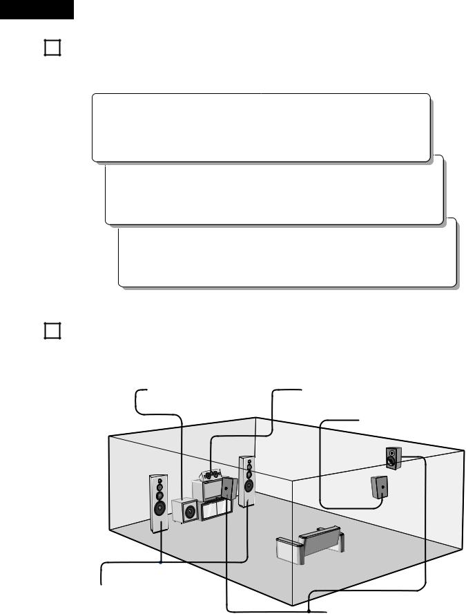
7 SETTING
2 Speaker system layout
Basic system layout
• The following is an example of the basic layout for a system consisting of seven speaker systems and a television monitor:
Subwoofer |
Center speaker system |
Surround back speaker system
Front speaker systems |
|
|
Set these at the sides of the TV or screen with |
|
|
their front surfaces as flush with the front of the |
Surround speaker systems |
|
screen as possible. |
||
|
8
ENGLISH
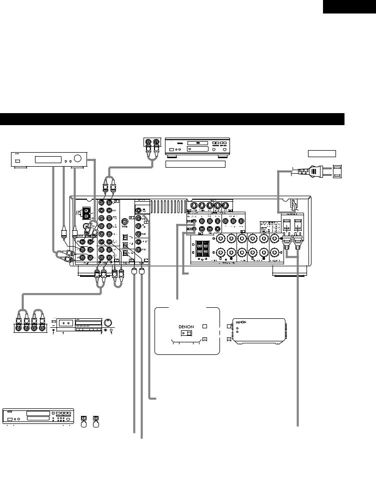
8 |
CONNECTIONS |
|
|
|
|
• |
Do not plug in the power cord until all connections have been |
• Note that binding pin plug cords together with power cords or |
|
completed. |
placing them near a power transformer will result in generating |
• |
Be sure to connect the left and right channels properly (left with |
hum or other noise. |
|
left, right with right). |
• Noise or humming may be generated if a connected audio |
• |
Insert the plugs securely. Incomplete connections will result in |
equipment is used independently without turning the power |
|
the generation of noise. |
of this unit on. If this happens, turn on the power of the this |
• |
Use the AC OUTLETS for audio equipment only. Do not |
unit. |
|
use them for hair driers, etc. |
|
|
|
|
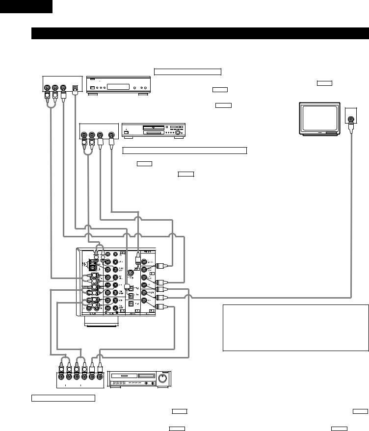
Connecting the audio components |
|
|
||||||
|
|
|
|
|
|
OUTPUT |
CD player |
|
|
|
|
|
|
|
R |
L |
|
Decoders with 6-channel |
|
|
|
|
|
|
|
|
analog outputs, etc. |
|
|
|
|
|
R |
L |
AC CORD |
|
|
|
|
|
|
|
|
|
|
|
|
|
|
LINE OUT |
|
AC 120V, 60Hz |
|
|
|
|
|
|
|
Connecting a CD player |
||
LINE OUT |
WOOFERSUB |
CENTER |
FRONT |
|
|
|
|
Connect the CD player’s analog output jacks |
SURROUND |
|
|
|
|
(ANALOG OUTPUT) to this unit’s CD jacks using |
|||
|
|
|
|
|
|
|
|
|
|
|
|
|
|
|
|
|
pin plug cords. |
|
|
|
|
R |
L |
|
|
|
|
|
|
R |
|
|
|
|
|
|
|
|
L |
|
|
|
|
|
|
|
L |
|
|
|
|
|
|
|
|
R |
|
|
|
|
|
|
|
|
|
R |
L |
R |
L |
|
Extension jacks for future use. |
|
|
|
|
|
|
LINE IN |
|
|
|
|
|
|
|
|
|
|
|
|
|
|
|
AUX OUT |
|||||||||||||||||||||||||||||||||||||
|
|
|
|
|
|
|
|
|
|
|
|
|
|
|
|
|
|
|
|
|
|
|
|
|
|
|
|
|
|
|
|
|
|
|
|
|
|
|
|
|
|
|
|
|
|
|
|
|
|||||||||||
|
|
|
|
|
|
|
|
|
|
|
LINE OUT |
|
|
|
|
|
|
|
|
|
|
|
|
|
|
|
|
|
|
|
RC-616 |
||||||||||||||||||||||||||||
|
|
|
|
|
|
|
|
|
|
|
|
|
|
|
Tape deck or CD recorder |
|
|
|
Another room |
|
|
|
|
(Sold Separately) |
|||||||||||||||||||||||||||||||||||
|
|
|
|
|
|
|
|
|
|
|
|
|
|
|
|
|
|
|
|
|
|
|
|
|
|
|
|
|
|
|
|
Infrared retransmitter |
|||||||||||||||||||||||||||
|
|
|
|
|
|
|
|
|
|
|
|
|
|
|
|
|
RC-617 (Sold Separately) |
|
|
|
|||||||||||||||||||||||||||||||||||||||
|
|
|
|
|
|
|
|
|
|
|
|
|
|
|
|
|
|
|
|
|
|
|
|
|
|
|
|
|
|
|
|
|
|
|
|
|
|
|
|
|
|||||||||||||||||||
|
|
|
|
|
R |
|
L |
|
R |
|
L |
|
|
|
|
|
|
|
|
|
|
|
|
|
|
|
|
|
|
|
|
|
|
|
|
|
|
Infrared sensor |
|
|
|
|
|
|
|
|
|
|
|||||||||||
|
|
|
|
|
|
|
|
|
|
|
|
|
|
|
|
|
|
|
|
|
|
|
|
|
|
|
|
|
|
|
|
|
|
|
|
|
|
|
|
|
|
|
|
|
|
+ |
|
|
+ |
|
|
|
|
|
|
|
|
|
|
|
|
|
|
|
|
|
|
|
|
|
|
|
|
|
|
|
|
|
|
|
|
|
|
|
|
|
|
|
|
|
|
|
|
|
|
|
|
|
|
|
|
|
|
|
|
|
|
|
|
|
|
|
|
|
|||||
|
|
|
|
|
R |
|
L |
|
R |
|
L |
|
|
|
|
|
|
|
|
|
|
|
|
|
|
|
|
|
|
|
|
|
|
|
|
|
|
|
|
|
|
|
|
|
|
|
|
|
|
|
|
|
|
|
|
||||
|
|
|
|
|
|
INPUT |
|
OUTPUT |
|
|
|
|
|
|
|
|
|
|
|
|
|
|
|
|
|
|
|
|
|
|
|
|
|||||||||||||||||||||||||||
|
|
|
|
|
|
|
|
|
|
|
|
|
|
|
|
|
|
|
|
|
|
|
|
|
|
|
|
|
|
|
|||||||||||||||||||||||||||||
|
|
|
|
|
|
|
|
|
|
|
|
|
|
|
|
|
|
|
|
|
|
|
|
|
|
|
|||||||||||||||||||||||||||||||||
Connecting a tape deck |
|
|
|
|
|
|
|
|
|
|
|
|
|
|
|
|
|
|
|
|
|
|
|
|
|
|
|||||||||||||||||||||||||||||||||
|
|
|
|
|
|
|
|
|
|
|
|
|
|
|
|
|
|
|
|
|
|
|
|
||||||||||||||||||||||||||||||||||||
|
|
|
|
|
|
|
|
OUTPUT INPUT |
|||||||||||||||||||||||||||||||||||||||||||||||||||
Connections for recording: |
|
|
|
|
|
|
|
|
|||||||||||||||||||||||||||||||||||||||||||||||||||
|
|
|
|
|
|
|
|
|
|
|
|
|
|
|
|
|
|
|
|
|
|
|
|
||||||||||||||||||||||||||||||||||||
Connect the tape deck’s recording input jacks (LINE IN or |
|
|
• When a sold separately room-to-room remote control unit |
||||||||||||||||||||||||||||||||||||||||||||||||||||||||
REC) to this unit’s tape recording (OUT) jacks using pin plug |
|
|
|||||||||||||||||||||||||||||||||||||||||||||||||||||||||
|
|
(DENON RC-616, 617 or 618) is wired and connected between |
|||||||||||||||||||||||||||||||||||||||||||||||||||||||||
cords. |
|
|
|
|
|
|
|
|
|
|
|
|
|
|
|
|
|
|
|
|
|
|
|
|
|
|
|
|
|
|
|
|
|||||||||||||||||||||||||||
|
|
|
|
|
|
|
|
|
|
|
|
|
|
|
|
|
|
|
|
|
|
|
|
|
|
|
|
|
|
|
|
the MAIN ROOM and ANOTHER ROOM, the remote- |
|||||||||||||||||||||||||||
Connections for playback: |
|
|
|||||||||||||||||||||||||||||||||||||||||||||||||||||||||
|
|
controllable devices in the main room can be controlled from |
|||||||||||||||||||||||||||||||||||||||||||||||||||||||||
Connect the tape deck’s playback output jacks (LINE OUT or |
|
|
|||||||||||||||||||||||||||||||||||||||||||||||||||||||||
|
|
ANOTHER ROOM using the remote control unit. |
|||||||||||||||||||||||||||||||||||||||||||||||||||||||||
PB) to this unit’s tape playback (IN) jacks using pin plug cords. |
|
|
|||||||||||||||||||||||||||||||||||||||||||||||||||||||||
|
|
|
|
|
|
|
|
|
|
|
|
|
|
|
|
|
|
|
|
|
|
|
|
||||||||||||||||||||||||||||||||||||
|
|
|
|
|
|
|
|
|
|
|
|
|
|
|
|
|
|||||||||||||||||||||||||||||||||||||||||||
CD recorder, MD recorder or other component |
|
|
Subwoofer jack |
|
|
|
|
|
|
|
|
|
|
|
|
|
|
|
|||||||||||||||||||||||||||||||||||||||||
equipped with digital output jacks. |
|
|
Connect the internal amplifier’s subwoofer to the subwoofer |
||||||||||||||||||||||||||||||||||||||||||||||||||||||||
|
|
|
|
|
|
|
|
|
|
|
|
|
|
|
|
|
|
|
|
|
|
|
OPTICAL |
|
|
terminal. (Refer to page 14.) |
|
|
|
|
|
|
|
|
|
|
|||||||||||||||||||||||
|
|
|
B |
|
|
|
|
|
|
|
|
|
|
|
|
|
|
|
|
|
|
|
|
|
|
|
|
|
|
|
|
|
|
|
|
|
|
|
|
|
|
|
|
|
|
||||||||||||||
|
|
|
|
|
|
|
|
|
|
|
|
|
|
|
|
|
|
|
|
|
|
OUTPUT INPUT |
|
|
|
|
|
|
|
|
|
|
|
|
|
|
|
|
|
|
|
|
|
|
|
|
|
|
|||||||||||
|
|
|
|
|
|
|
|
|
|
|
|
|
|
|
|
|
|
|
|
|
|
|
|
|
|
|
|
|
|
|
|
|
|
|
|
|
|
|
|
|
|
|
|
|
|
|
|
|
|
|
|
|
|
|
|
|
|
||
|
|
|
|
|
|
|
|
|
|
|
|
|
|
|
|
|
|
|
|
|
|
|
|
|
|
|
|
|
|
|
|
|
|
|
|
|
AC OUTLETS |
Connecting the AC OUTLETS |
|
||||||||||||||||||||
|
|
|
|
|
|
|
|
|
|
|
|
|
|
|
|
|
|
|
|
|
|
|
|
|
|
|
|
|
|
|
|
|
|
|
|
|
|
|
|
|
|
|
|
|
|
|
|
||||||||||||
|
|
|
|
|
|
|
|
|
|
|
|
|
|
|
|
|
|
|
|
|
|
|
|
|
|
|
|
|
|
|
|
|
|
|
|
|
|
|
|
|
|
|
|
|
|
|
|
||||||||||||
|
|
|
|
|
|
|
|
|
|
|
|
|
|
|
|
|
|
|
|
|
|
|
|
|
|
|
|
|
|
|
|
|
|
|
|
|
|
|
|
|
|
|
|
|
|
||||||||||||||
DIGITAL jacks |
|
|
|
|
|
|
|
|
|
|
|
|
|
|
|
|
|
|
|
|
|
|
|
|
|
|
• SWITCHED |
|
|
|
|
|
|
|
|
|
|
||||||||||||||||||||||
Use these for connections to audio equipment with digital output. |
|
|
(total capacity – 120 W (1 A.)) |
|
|
|
|
|
|
|
|
|
|
||||||||||||||||||||||||||||||||||||||||||||||
Refer to Page 25 for instructions on setting this terminal. |
|
|
The power to these outlets is turned on and off in conjunction with the POWER switch |
||||||||||||||||||||||||||||||||||||||||||||||||||||||||
|
|
|
|
|
|
|
|
|
|
|
|
|
|
|
|
|
|
|
|
|
|
|
|
|
|
|
|
|
|
|
|
|
|
|
|
|
|
on the main unit, and when the power is switched between on and standby from the |
|||||||||||||||||||||
|
|
• Use 75 Ω |
/ohms cable pin cords (sold separately) for coaxial |
|
|
||||||||||||||||||||||||||||||||||||||||||||||||||||||
|
|
|
|
|
remote control unit. |
|
|
|
|
|
|
|
|
|
|
||||||||||||||||||||||||||||||||||||||||||||
|
|
|
connections. |
|
|
|
|
|
|
|
|
|
|
|
|
|
|
|
|
|
|
|
|
|
|
|
|
|
|
|
No power is supplied from these outlets when this unit’s power is at standby. Never |
||||||||||||||||||||||||||||
|
|
• Use optical cables (sold separately) for optical connections. |
|
|
|
||||||||||||||||||||||||||||||||||||||||||||||||||||||
|
|
|
|
|
connect equipment whose total capacity is above 120 W (1 A.) |
||||||||||||||||||||||||||||||||||||||||||||||||||||||
|
|
|
|
|
|
|
|
|
|
|
|
|
|
|
|
|
|
|
|
|
|
|
|
|
|
|
|
|
|
|
|
|
|
|
|
|
|
||||||||||||||||||||||
|
|
|
|
|
|
|
|
|
|
|
|
|
|
|
|
|
|
|
|
|
|
|
|
|
|
|
|
|
|
|
|
|
|
|
|
|
NOTE: |
|
|
|
|
|
|
|
|
|
|
||||||||||||
|
|
|
|
|
|
|
|
|
|
|
|
|
|
|
|
|
|
|
|
|
|
|
|
|
|
|
|
|
|
|
|
|
|
|
|
|
|
Only use the AC OUTLETS for audio equipment. Never use them for hair driers, TVs or |
|||||||||||||||||||||
|
|
|
|
|
|
|
|
|
|
|
|
|
|
|
|
|
|
|
|
|
|
|
|
|
|
|
|
|
|
|
|
|
|
|
|
|
|
other electrical appliances. |
|
|
|
|
|
|
|
|
|
|
|||||||||||
|
|
|
|
|
|
|
|
|
|
|
|
|
|
|
|
|
|
|
|
|
|
|
|
|
|
|
|
|
|
|
|
|
|
|
|
|
|
|
|
|
|
|
|
|
|
|
|
|
|
|
|
|
|
|
|
|
|
|
|
9
ENGLISH
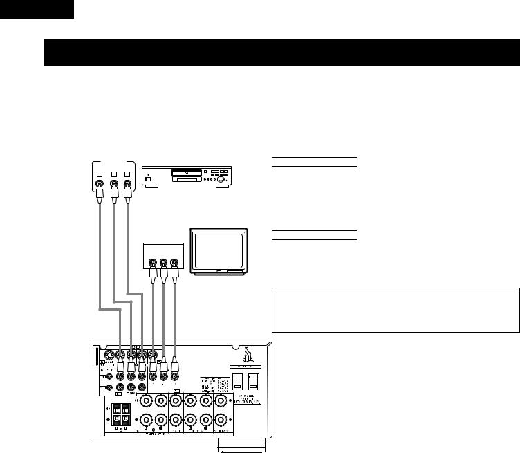
Connecting the video equipments
To connect the video signal, connect using a 75 Ω /ohms video signal cable cord. Using an improper cable can result in a drop in sound quality.
|
|
|
|
TV or DBS tuner |
AUDIO |
VIDEO |
DIGITAL |
B |
|
R |
OUT |
OUT |
OUT |
|
L |
OPTICAL |
|
||
R |
L |
|
|
|
OUT |
OUT |
AUDIO |
VIDEO DIGITAL |
|
AUDIO |
|
R |
OUT |
OUT |
VIDEO |
L |
OUT COAXIAL |
||
R |
L |
|
||
|
|
|
||
|
|
AUDIO OUT |
|
VIDEO OUT |
 R
R 
 L
L 

Connecting a TV/DBS tuner |
|
MONITOR OUT |
|
|
TV/DBS |
|
|
• Connect the TV’s video input jack (VIDEO |
|
• Connect the TV’s or DBS tuner’s video output jack |
INPUT) to the |
VIDEO MONITOR OUT |
||
(VIDEO OUTPUT) to the |
VIDEO |
(yellow) TV/DBS IN |
jack using a 75 Ω |
/ohms video coaxial pin |
jack using a 75 Ω /ohms video coaxial pin plug cord. |
plug cord. |
|
||
• Connect the TV’s or DBS tuner’s audio output jacks |
|
|
||
(AUDIO OUTPUT) to the |
AUDIO |
TV/DBS IN jacks |
|
|
using pin plug cords. |
|
|
|
VIDEO |
|
|
|
|
IN |
B |
|
|
|
|
DVD player or VDP |
|
|
|
|
|
|
|
Monitor TV |
|
Connecting a DVD player or a video disc player (VDP) |
|
IN |
||
|
VIDEO |
|||
• Connect the DVD player’s (video disc player’s) video output jack (VIDEO OUTPUT) to |
||||
the VIDEO (yellow) DVD/VDP IN jack using a 75 Ω |
/ohms video coaxial pin plug cord. |
|||
• Connect the DVD player’s (video disc player’s) analog audio output jacks (ANALOG AUDIO OUTPUT) to the AUDIO DVD/VDP IN jacks using pin plug cords.
•For better sound quality, we recommend using the DVD player with digital rather than analog connections.
DVD and VDP players can also be connected to the VCR terminals.
|
|
|
|
R |
|
|
|
|
|
L |
|
|
|
|
|
R |
|
|
|
|
|
L |
|
|
|
|
|
R |
|
|
|
|
|
L |
|
AUDIO OUT |
AUDIO IN |
|
|
VIDEO IN |
|
|
|
|
|
|
|
|
|
|
|
Video deck |
VIDEO OUT |
|
R |
L |
R |
|
|
|
L |
|
NOTE:
Connection of the video disc Player Equipped with Dolby Digital RF Output Jack.
•Please use a commercially available adaptor when connecting the Dolby Digital RF output jack of the video disc player to the digital input jack.
Please refer to the instruction manual of the adapter when making connections.
R |
|
|
L |
R |
|
L OUT IN |
|
OUT |
|
IN |
|||
|
|
|
AUDIO |
|
VIDEO |
|
|
|
|
|
|||
Connecting a video decks
Video input/output connections:
• Connect the video deck’s video output jack (VIDEO OUT) to the VIDEO (yellow) VCR IN jack, and the video deck’s video input jack (VIDEO IN) to the VIDEO (yellow) VCR OUT jack using 75 Ω /ohms video coaxial pin plug cords.
Connecting the audio output jacks:
•Connect the video deck’s audio output jacks (AUDIO OUT) to the AUDIO VCR IN jacks, and the video deck’s audio input jacks (AUDIO IN) to the AUDIO VCR OUT jacks using pin plug cords.
10
ENGLISH
L |
R |
Video game
OUTPUT
R |
L |
OPTICAL |
VIDEO OUT |
||||||
|
|
|
|
|
|
|
|
|
|
R |
L |
LINE OUT |
DIGITAL OUT |
VIDEO OUT |
Connecting a Video game equipment
•Connect the Video game equipment’s output jacks to this unit’s V. AUX INPUT jacks.
Video camera
OUTPUT
R L |
VIDEO OUT |
R |
L |
LINE OUT VIDEO OUT
Connecting a Video camera equipment
•Connect the video camera equipment’s output jacks to this unit’s V. AUX INPUT jacks.

 The V. AUX terminal is covered with a cap. Remove this cap in order to use the terminal. (See page 4 for instructions on removing the cap.)
Connecting a video component equipped with S-video jacks
•When marking connections, also refer to the operating instructions of the other components.
•A note on the S input jacks
The input selectors for the S inputs and pin jack inputs work in conjunction with each other.
•Precaution when using S-jacks
This unit’s S-jacks (input and output) and video pin jacks (input and output) have independent circuit structures, so that video signals input from the S-jacks are only output from the S-jack outputs and video signals input from the pin jacks are only output from the pin jack outputs. When connecting this unit with equipment that is equipped with S-jacks, keep the above point in mind and make connections according to the equipment’s instruction manuals.
VIDEO OUT
DVD player, VDP, etc. |
Monitor TV |
|
S-VIDEO B |
|
|
Connecting a monitor TV |
OUT |
|
|
MONITOR OUT |
|
S-VIDEO |
|
|
|
|
• Connect the TV’s or DBS tuner’s S video input |
|
|
IN |
|
|
|
|
|
|
Connecting a DVD player or video disc player (VDP) |
|
|
(S-VIDEO INPUT) to the S-VIDEO MONITOR |
|
|
OUT jack using a S jack connection cord. |
|
|
|
|
|
DVD/VDP |
|
|
|
• Connect the DVD player’s or video disc player’s S- |
IN |
|
|
Video output jack to the S-VIDEO DVD/VDP IN jack |
|
|
|
using an S-Video connection cord. |
VIDEO |
S-VIDEO |
B |
|
OUT |
TV or satellite broadcast tuner |
|
|
|
||
|
|
|
|
|
|
|
Connecting a TV/DBS tuner |
|
|
|
• Connect the TV’s or DBS tuner’s S |
|
VIDEO OUT |
video output jack (S-VIDEO OUTPUT) |
|
|
to the S-VIDEO TV/DBS IN jack using |
||
|
|
|
an S jack connection cord. |
VIDEO OUT |
VIDEO IN
Connecting the video decks
•Connect the video deck’s S output jack (S-OUT) to the S-VIDEO VCR IN jack and the video deck’s S input jack (S-IN) to the
S-VIDEO VCR OUT jack using S jack connection cords.
S-VIDEO |
|
OUT IN |
Video deck |
|
Connect the components’ audio inputs and outputs as described on page 10.
11
ENGLISH
Connecting a Video Component Equipped with Color Difference (Component - Y, PR/CR, PB/CB) Video Jacks (DVD Player)
•When making connections, also refer to the operating instructions of the other components.
•The signals input to the color difference (component) video jacks are not output from the VIDEO output jack (yellow) or the S-Video output jack. In addition, the video signals input to the VIDEO input (yellow) and S-Video input jacks are not output to the color difference (component) video jacks.
•Some video sources with component video outputs are labeled Y, CB, CR, or Y, Pb, Pr, or Y, R-Y, B-Y. These terms all refer to component video color difference output.
COMPONENT |
DVD player |
Connecting a DVD player |
VIDEO OUT |
|
|
B
Y |
|
CB |
|
|
CR |
|
|||
|
|
|
|
|
|
|
|
|
|
|
|
|
|
|
|
|
|
|
|
|
|
|
|
|
|
|
|
|
|
DVD IN jacks
•Connect the DVD player’s color difference (component) video output jacks (COMPONENT VIDEO OUTPUT) to the COMPONENT DVD IN jack using 75 Ω /ohms coaxial video pin-plug cords.
•In the same way, another video source with component video outputs such as a TV/DBS tuner, etc., can be connected to the TV/DBS color difference (component) video jacks.
Monitor TV
COMPONENT
VIDEO IN
Y CB CR
Connecting a monitor TV
MONITOR OUT jack
•Connect the TV’s color difference (component) video input jacks (COMPONENT VIDEO INPUT) to the COMPONENT MONITOR OUT jack using 75 Ω /ohms coaxial video pin-plug cords.
•The color difference input jacks may be indicated differently on some TVs, monitors or video components (“CR, CB and Y”, “R-Y, B-Y and Y”, “Pr, Pb and Y”, etc.). For details, carefully read the operating instructions included with the TV or other component.
12
ENGLISH
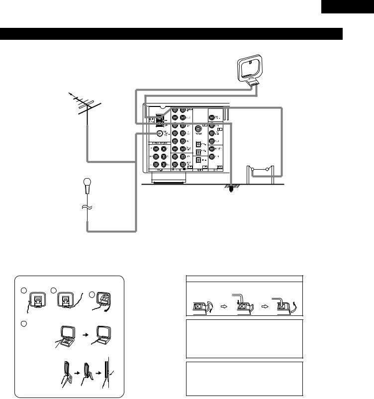
Connecting the antenna terminals |
|
|
|
AM LOOP |
|
|
ANTENNA |
|
|
(An Accessory) |
|
DIRECTION OF |
|
|
BROADCASTING |
|
|
STATION |
|
|
FM ANTENNA |
|
|
75 Ω /ohms |
|
|
COAXIAL |
|
|
CABLE |
|
|
|
AM OUTDOOR |
|
|
ANTENNA |
|
FM INDOOR ANTENNA |
GROUND |
|
(An Accessory) |
||
|
AM loop antenna assembly
|
|
Connect to the AM |
|
1 |
2 |
antenna terminals. |
|
3 |
|||
|
|
||
|
Remove the vinyl tie |
|
|
|
and take out the |
Bend in the reverse |
|
4 |
connection line. |
direction. |
|
|
|
a.With the antenna on top any stable
surface.
Mount
b. With the antenna attached to a wall.
Installation hole
Mount on wall, etc.
Connection of AM antennas
1. Push the lever. |
2. Insert the |
3. Return the lever. |
||||
|
conductor. |
|
|
|
|
|
|
|
|
|
|
|
|
|
|
|
|
|
|
|
|
|
|
|
|
|
|
|
|
|
|
|
|
|
|
|
|
|
|
|
|
Note to CATV system installer:
This reminder is provided to call the CATV system installer’s attention to Article 820-40 of the NEC which provides guidelines for proper grounding and, in particular, specifies that the cable ground shall be connected to the grounding system of the building, as close to the point of cable entry as practical.
Notes:
•Do not connect two FM antennas simultaneously.
•Even if an external AM antenna is used, do not disconnect the AM loop antenna.
•Make sure AM loop antenna lead terminals do not touch metal parts of the panel.
13
ENGLISH
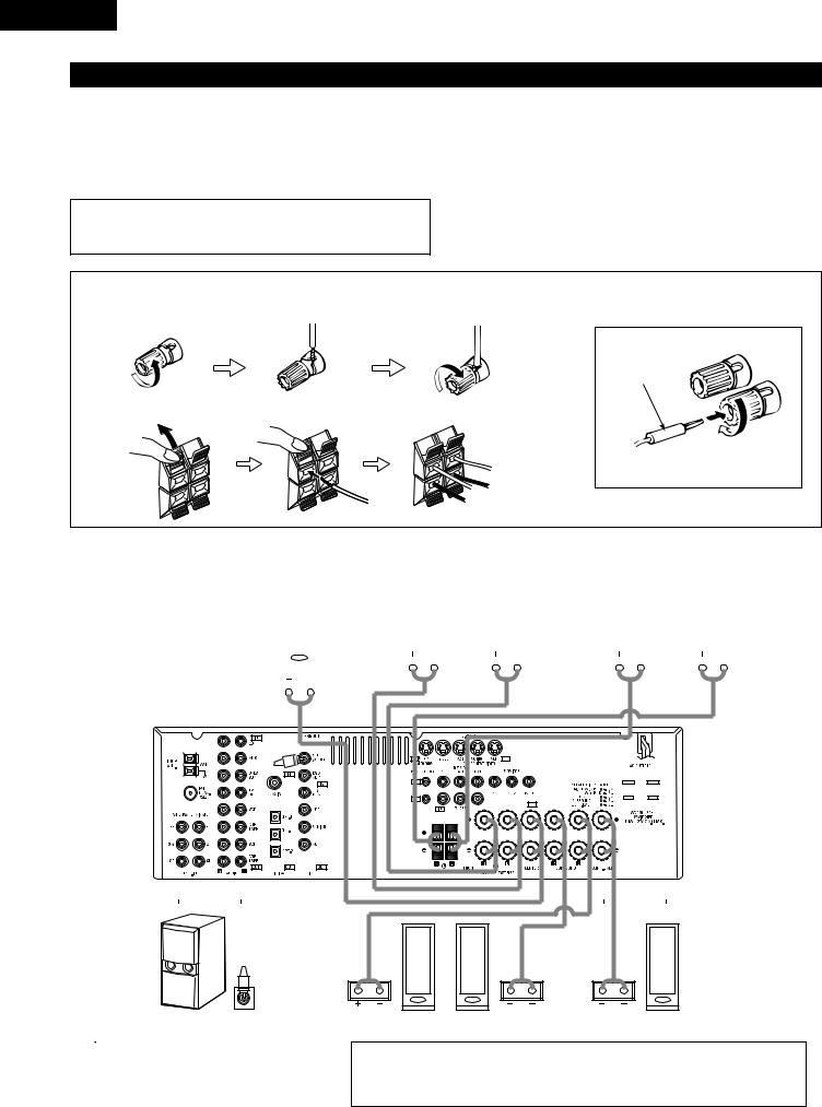
Speaker system connections
•Connect the speaker terminals with the speakers making sure that like polarities are matched (<with <, >with >). Mismatching of polarities will result in weak central sound, unclear orientation of the various instruments, and the sense of direction of the stereo being impaired.
•When making connections, take care that none of the individual conductors of the speaker cord come in contact with adjacent terminals, with other speaker cord conductors, or with the rear panel.
NOTE:
NEVER touch the speaker terminals when the power is on.
Doing so could result in electric shocks.
Speaker Impedance
•When speaker systems A and B are use separately, speakers with an impedance of 6 to 16 Ω /ohms can be connected for use as front speakers.
•Be careful when using two pairs of front speakers (A + B) at the same time, since use of speakers with an impedance of 12 to 16 Ω /ohms.
•Speakers with an impedance of 6 to 16 Ω /ohms can be connected for use as center and surround and surround back speakers.
•The protector circuit may be activated if the set is played for long periods of time at high volumes when speakers with an impedance lower than the specified impedance are connected.
|
|
Connecting the speaker cords |
1. Loosen by turning |
2. Insert the cord. |
3. Tighten by turning |
counterclockwise. |
|
clockwise. |
Connecting banana plugs
banana plug
1. Push the lever. |
2. Insert the cord. |
3. Return the lever. |
Turn clockwise to tighten, then insert the banana plug.
CENTER SPEAKER SYSTEM |
|
FRONT SPEAKER SYSTEMS |
|
FRONT SPEAKER SYSTEMS |
|
|
System A |
System B |
|
|
|
|
|
|
|
|
|
|
|
|
|
|
|
|
|
|
|
|
|
|
|
|
|
|
|
|
|
|
|
|
|
|
|
|
|
|
|
|
|
|
|
|
|
|
|
|
|
|
|
|
|
|
|
|
|
|
|
|
|
|
|
|
|
|
|
|
|
|
|
|
|
|
|
|
|
|
|
|
|
|
|
|
|
|
|
|
|
|
|
(L) |
|
|
|
|
(R) |
|
|
|
|
|
(L) |
|
|
|
|
|
|
|
(R) |
|
|||||||||||||||||||||
|
|
|
|
|
|
|
|
|
|
|
|
|
|
|
|
|
|
|
|
|
|
|
|
|
|
|
|
|
|
|
|
|
|
|
|
|
|
|
|
|
|
|
|
|
|
|
|
|
|
|
|
|
|
|
|
|
|
|
|
|
|
|
|
|
|
|
|
|
|
|
|
|
|
|
|
|
|
|
|
|
|
|
|
|
|
|
|
|
|
|
|
|
|
|
|
|
|
|
|
|
|
|
|
|
|
|
|
|
|
|
|
|
|
|
|
|
|
|
|
|
|
|
|
|
|
|
|
|
|
|
|
|
|
|
|
|
|
|
|
|
|
|
|
|
|
|
|
|
|
|
|
|
|
|
|
|
|
|
|
|
|
|
|
|
|
|
|
|
|
|
|
|
|
|
|
|
|
|
|
|
|
|
|
|
|
|
|
|
|
|
|
|
|
|
|
|
|
|
|
|
|
|
|
|
|
|
|
|
|
|
|
|
|
|
|
|
|
|
|
|
|
|
|
|
|
|
|
|
|
|
|
|
|
|
|
|
|
|
|
|
|
|
|
|
|
|
|
|
|
|
|
|
|
|
|
|
|
|
|
|
|
|
|
|
|
|
|
|
|
|
|
|
|
|
|
|
|
|
|
|
|
|
|
|
|
|
|
|
|
|
|
|
|
|
|
|
|
|
|
|
|
|
|
|
|
|
|
|
|
|
|
|
|
|
|
|
|
|
|
|
|
|
|
|
|
|
|
|
|
|
|
|
|
|
|
|
|
|
|
|
|
|
|
|
|
|
|
|
|
|
|
|
|
|
|
|
|
|
|
|
|
|
|
|
|
|
|
|
|
|
|
|
|
|
|
|
|
|
|
|
|
|
|
|
|
|
|
|
|
|
|
|
|
|
|
|
|
|
|
|
|
|
|
|
|
|
|
|
|
|
|
|
|
|
|
|
|
|
|
|
|
|
|
|
|
|
|
|
|
|
|
|
|
|
|
|
|
|
|
|
|
|
|
|
|
|
|
|
|
|
|
|
|
|
|
|
|
|
|
|
|
|
|
|
|
|
|
|
|
|
|
|
|
|
|
|
|
|
|
|
|
|
|
|
|
|
|
|
|
|
|
|
|
|
|
|
|
|
|
|
|
|
|
|
|
|
|
|
|
|
|
|
|
|
|
|
|
|
|
|
|
|
|
|
|
|
|
|
|
|
|
|
|
|
|
|
|
|
|
|
|
|
|
|
|
|
|
|
|
|
|
|
|
|
|
|
|
|
|
|
|
|
|
|
|
|
|
|
|
|
|
|
|
|
|
|
|
|
|
|
|
|
|
|
|
|
|
|
|
|
|
|
|
|
|
|
|
|
|
|
|
|
|
|
|
|
|
|
|
|
|
|
|
|
|
|
|
|
|
|
|
|
|
|
|
|
|
|
|
|
|
|
|
|
|
|
|
|
|
|
|
|
|
|
|
|
|
|
|
|
|
|
|
|
|
|
|
|
|
|
|
|
|
|
|
|
|
|
|
|
|
|
|
|
|
|
|
|
|
|
|
|
|
|
|
|
|
|
|
|
|
|
|
|
|
|
|
|
|
|
|
|
|
|
|
|
|
|
|
|
|
|
|
|
|
|
|
|
|
|
|
|
|
|
|
|
|
|
|
|
|
|
|
|
|
|
|
|
|
|
|
|
|
|
|
|
|
|
|
|
|
|
|
|
|
|
|
|
|
|
|
|
|
|
|
|
|
|
|
|
|
|
|
|
|
|
|
|
|
|
|
|
|
|
|
|
|
|
|
|
|
|
|
|
|
|
|
|
|
|
|
|
|
|
|
|
|
|
|
|
|
|
|
|
|
|
|
|
|
|
|
|
|
|
|
|
|
|
|
|
|
|
|
|
|
|
|
|
|
|
|
|
|
|
|
|
|
|
|
|
|
|
|
|
|
|
|
|
|
|
|
|
|
|
|
|
|
|
|
|
|
|
|
|
|
|
|
|
|
|
|
|
|
|
|
|
|
|
|
|
|
|
|
|
|
|
|
|
|
|
|
|
|
|
|
|
|
|
|
|
|
|
|
|
|
|
|
|
|
|
|
|
|
|
|
|
|
|
|
|
|
|
|
|
|
|
|
|
|
|
|
|
|
|
|
|
|
|
|
|
|
|
|
|
|
|
|
|
|
|
|
|
|
|
|
|
|
|
|
|
|
|
|
|
|
|
|
|
|
|
|
|
|
|
|
|
|
|
|
|
|
|
|
|
|
|
|
|
|
|
|
|
|
|
|
|
|
|
|
|
|
|
|
|
|
|
|
|
|
|
|
|
|
|
|
|
|
|
|
|
|
|
|
|
|
|
|
|
|
|
|
|
|
|
|
|
|
|
|
|
|
|
|
|
|
|
|
|
|
|
|
|
|
|
|
|
|
|
|
|
|
|
|
|
|
|
|
|
|
|
|
|
|
|
|
|
|
|
|
|
|
|
|
|
|
|
|
|
|
|
|
|
|
|
|
|
|
|
|
|
|
|
|
|
|
|
|
|
|
|
|
|
|
|
|
|
|
|
|
|
|
|
|
|
|
|
|
|
|
|
|
|
|
|
|
|
|
|
|
|
|
|
|
|
|
|
|
|
|
|
|
|
|
|
|
|
|
|
|
|
|
|
|
|
|
|
|
|
|
|
|
|
|
|
|
|
|
|
|
|
|
|
|
|
|
|
|
|
|
|
|
|
|
|
|
|
|
|
|
|
|
|
|
|
|
|
|
|
|
|
|
|
|
|
|
|
|
|
|
|
|
|
|
|
|
|
|
|
|
|
|
|
|
|
|
|
|
|
|
|
|
|
|
|
|
|
|
|
|
|
|
|
|
|
|
|
|
|
|
|
|
|
|
|
|
|
|
|
|
|
|
|
|
|
|
|
|
|
|
|
|
|
|
|
|
|
|
|
|
|
|
|
|
|
|
|
|
|
|
|
|
|
|
|
|
|
|
|
|
|
|
|
|
|
|
|
|
|
|
|
|
|
|
|
|
|
|
|
|
|
|
|
|
|
|
|
|
|
|
|
|
|
|
|
|
|
|
|
|
|
|
|
|
|
|
|
|
|
|
|
|
|
|
|
|
|
|
|
|
|
|
|
|
|
|
|
|
|
|
|
|
|
|
|
|
|
|
|
|
|
|
|
|
|
|
|
|
|
|
|
|
|
|
|
|
|
|
|
|
|
|
|
|
|
|
|
|
|
|
|
|
|
|
|
|
|
|
|
|
|
|
|
|
|
|
|
|
|
|
|
|
|
|
|
|
|
|
|
|
|
|
|
|
|
|
|
|
|
|
|
|
|
|
|
|
|
|
|
|
|
|
|
|
|
|
|
|
|
|
|
|
|
|
|
|
|
|
|
|
|
|
|
|
|
|
|
|
|
|
|
|
|
|
|
|
|
|
|
|
|
|
|
|
|
|
|
|
|
|
|
|
|
|
|
|
|
|
|
|
|
|
|
|
|
|
|
|
|
|
|
|
|
|
|
|
|
|
|
|
|
|
|
|
|
|
|
|
|
|
|
|
|
|
|
|
|
|
|
|
|
|
|
|
|
|
|
|
|
|
|
|
|
|
|
|
|
|
|
|
|
|
|
|
|
|
|
|
|
|
|
|
|
|
|
|
|
|
|
|
|
|
|
|
|
|
|
|
|
|
|
|
|
|
|
|
|
|
|
|
|
|
|
|
|
|
|
|
|
|
|
|
|
|
|
|
|
|
|
|
|
|
|
|
|
|
|
|
|
|
|
|
|
|
|
|
|
|
|
|
|
|
|
|
|
|
|
|
|
|
|
|
|
|
|
|
|
|
|
|
|
|
|
|
|
|
|
|
|
|
|
|
|
|
|
|
|
|
|
|
|
|
|
|
|
|
|
|
|
|
|
|
|
|
|
|
|
|
|
|
|
|
|
|
|
|
|
|
|
|
|
|
|
|
|
|
|
|
|
|
|
|
|
|
|
|
|
|
|
|
|
|
|
|
|
|
|
|
|
|
|
|
|
|
|
|
|
|
|
|
|
|
|
|
|
|
|
|
|
|
|
|
|
|
|
|
|
|
|
|
|
|
|
|
|
|
|
|
|
|
|
|
|
|
|
|
|
|
|
|
|
|
|
|
|
|
|
|
|
|
|
|
|
|
|
|
|
|
|
|
|
|
|
|
|
|
|
|
|
|
|
|
|
|
|
|
|
|
|
|
|
|
|
|
|
|
|
|
|
|
|
|
|
|
|
|
|
|
|
|
|
|
|
|
|
|
|
|
|
|
|
|
|
|
|
|
|
|
|
|
|
|
|
|
|
|
|
|
|
|
|
|
|
|
|
|
|
|
|
|
|
|
|
|
|
|
|
|
|
|
|
|
|
|
|
|
|
|
|
|
|
|
|
|
|
|
|
|
|
|
|
|
|
|
|
|
|
|
|
|
|
|
|
|
|
|
|
|
|
|
|
|
|
|
|
|
|
|
|
|
|
|
|
|
|
|
|
|
|
|
|
|
|
|
|
|
|
|
|
|
|
|
|
|
|
|
|
|
|
|
|
|
|
|
|
|
|
|
|
|
|
|
|
|
|
|
|
|
|
|
|
|
|
|
|
|
Connection jack for subwoofer with built-in amplifier (super woofer), etc.

 To achieve Dolby Digital playback effect, use a unit that can sufficiently reproduce frequencies of under 80 Hz.
(L) (R)
SURROUND SPEAKER SYSTEMS |
|
SURROUND BACK SPEAKER SYSTEM |
•Precautions when connecting speakers
If a speaker is placed near a TV or video monitor, the colors on the screen may be disturbed by the speaker’s magnetism. If this should happen, move the speaker away to a position where it does not have this effect.
14

ENGLISH
Protector circuit
•This unit is equipped with a high-speed protection circuit. The purpose of this circuit is to protect the speakers under circumstances such as when the output of the power amplifier is inadvertently short-circuited and a large current flows, when the temperature surrounding the unit becomes unusually high, or when the unit is used at high output over a long period which results in an extreme temperature rise.
When the protection circuit is activated, the speaker output is cut off and the power supply indicator LED flashes. Should this occur, please follow these steps: be sure to switch off the power of this unit, check whether there are any faults with the wiring of the speaker cables or input cables, and wait for the unit to cool down if it is very hot. Improve the ventilation condition around the unit and switch the power back on.
If the protection circuit is activated again even though there are no problems with the wiring or the ventilation around the unit, switch off the power and contact a DENON service center.
Note on speaker impedance
•The protector circuit may be activated if the set is played for long periods of time at high volumes when speakers with an impedance lower than the specified impedance (for example speakers with an impedance of lower than 4 Ω /ohms)
are connected. If the protector circuit is activated, the speaker output is cut off. Turn off the set’s power, wait for the set to cool down, improve the ventilation around the set, then turn the power back on.
15
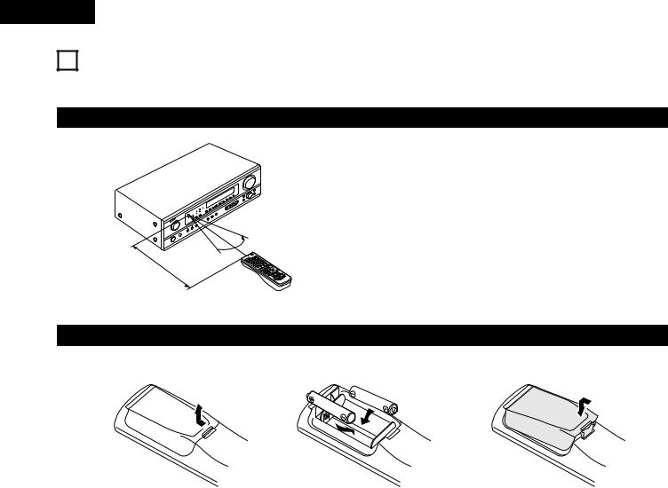
ENGLISH
9 USING THE REMOTE CONTROL UNIT
Following the procedure outlined below, insert the batteries before using the remote control unit.
Range of operation of the remote control unit

 30° 30°


Approx. 23 feet/7 m
Point the remote control unit at the remote control sensor as shown on the diagram at the left.
NOTES:
•The remote control unit can be used from a straight distance of approximately 23 feet/7 meters, but this distance will shorten or operation will become difficult if there are obstacles between the remote control unit and the remote control sensor, if the remote control sensor is exposed to direct sunlight or other strong light, or if operated from an angle.
•Neon signs or other devices emitting pulse-type noise nearby may result in malfunction, so keep the set as far away from such devices as possible.
Inserting the batteries
qPress as shown by the arrow and slide off.
w Insert the R6P/AA batteries properly, as |
e Close the lid. |
shown on the diagram. |
|
NOTES:
•Use only R6P/AA batteries for replacement.
•Be sure the polarities are correct. (See the illustration inside the battery compartment.)
•Remove the batteries if the remote control transmitter will not be used for an extended period of time.
•If batteries leak, dispose of them immediately. Avoid touching the leaked material or letting it come in contact with clothing, etc. Clean the battery compartment thoroughly before installing new batteries.
•Have replacement batteries on hand so that the old batteries can be replaced as quickly as possible when the time comes.
•Even if less than a year has passed, replace the batteries with new ones if the set does not operate even when the remote control unit is operated nearby the set. (The included battery is only for verifying operation. Replace it with a new battery as soon as possible.)
16
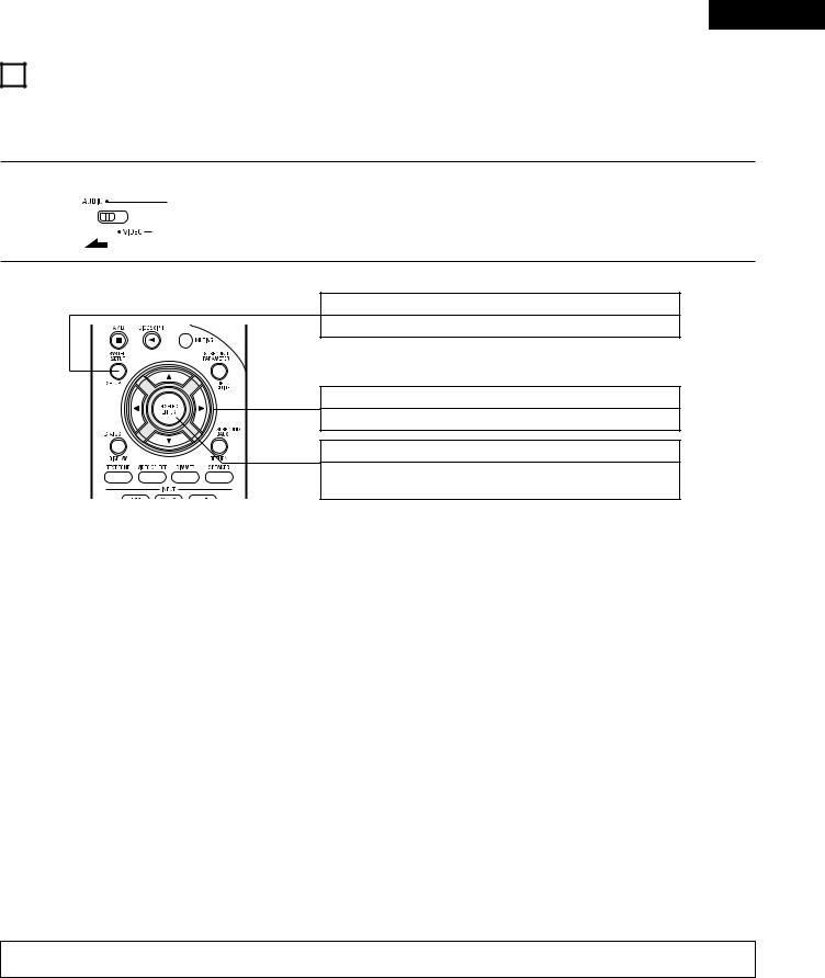
ENGLISH
10SETTING UP THE SYSTEM
•Once all connections with other AV components have been completed as described in “CONNECTIONS” (see pages 9 to 15), make the various settings described below on the display.
These settings are required to set up the listening room’s AV system centered around the this unit.
1 |
Set the slide switch to “AUDIO”. |
|
2 |
Use the following buttons to set up the system: |
|
SYSTEM SETUP button
Press this to display the system setup on the display.
CURSOR buttons (•, ª, 0, 1)
Press this change what appears on the display.
ENTER button
Press this to switch the display.
Also use this button to complete the setting.
• System setup items and default values (set upon shipment from the factory)
|
System setup |
|
|
|
|
|
|
|
|
Default settings |
|
|
|
||
|
|
|
|
|
|
|
|
|
|
|
|
|
|
|
|
Speaker |
Input the combination of speakers in your system and their |
Front Sp. |
|
Center Sp. |
Surround Sp. |
|
Surround back Sp. |
Subwoofer |
|||||||
corresponding sizes (SMALL for regular speakers, LARGE for full-size, |
|
|
|||||||||||||
|
|
|
|
|
|
|
|
|
|
|
|
|
|||
Configuration |
full-range) to automatically set the composition of the signals output |
Large |
|
|
Small |
|
Small |
|
Small |
|
Yes |
||||
|
from the speakers and the frequency response. |
|
|
|
|
|
|
||||||||
|
|
|
|
|
|
|
|
|
|
|
|
|
|
|
|
Subwoofer Mode |
This selects the subwoofer speaker for playing deep bass signals. |
|
|
|
|
|
Subwoofer mode = Normal |
|
|
|
|||||
|
|
|
|
|
|
|
|
|
|
|
|
|
|
|
|
Crossover |
Set the frequency (Hz) below which the bass sound of the various |
|
|
|
|
|
|
|
80 Hz |
|
|
|
|
|
|
Frequency |
speakers is to be output from the subwoofer. |
|
|
|
|
|
|
|
|
|
|
|
|
|
|
|
|
|
|
|
|
|
|
|
|
|
|
|
|
||
|
|
|
|
|
|
|
|
|
|
|
|
|
|
||
|
This parameter is for optimizing the timing with which |
the audio |
Front L |
|
Front R |
|
Center |
|
Surround L |
Surround R |
Surround Back |
Subwoofer |
|||
Delay Time |
signals are produced from the speakers and subwoofer according to |
|
|
|
|
|
|
|
|
|
|
|
|
|
|
|
|
|
|
|
|
|
|
|
|
|
|
|
|||
|
the listening position. |
|
12 ft |
|
12 ft |
|
12 ft |
|
10 ft |
|
10 ft |
10 ft |
|
12 ft |
|
|
|
|
|
|
|
|
|
||||||||
|
|
|
|
|
|
|
|
|
|
|
|
|
|
|
|
|
This adjusts the volume of the signals output from the speakers and |
Front L |
|
Front R |
|
Center |
|
Surround L |
Surround R |
Surround Back |
Subwoofer |
||||
Test Tone |
subwoofer for the different channels in order to obtain optimum |
|
|
|
|
|
|
|
|
|
|
|
|
|
|
|
|
|
|
|
|
|
|
|
|
|
|
|
|||
|
effects. |
|
0 dB |
|
0 dB |
|
0 dB |
|
0 dB |
|
0 dB |
0 dB |
|
0 dB |
|
|
|
|
|
|
|
|
|
|
|
|
|
|
|
|
|
|
|
Digital |
COAXIAL |
|
OPTICAL 1 |
|
OPTICAL 2 |
|
|
|
|
|
|||
Digital In |
This assigns the digital input jacks for the different input |
Inputs |
|
|
|
|
|
|
|
||||||
|
|
|
|
|
|
|
|
|
|
|
|
|
|||
Assignment |
sources. |
Input |
CD |
|
DVD/VDP |
|
TV/DBS |
|
|
|
|
|
|||
|
|
source |
|
|
|
|
|
|
|
||||||
|
|
|
|
|
|
|
|
|
|
|
|
|
|
|
|
|
|
|
|
|
|
|
|
|
|
|
|
|
|
|
|
Auto Surround |
Auto surround mode function setting. |
|
|
|
|
|
|
Auto Surround Mode = ON |
|
|
|
||||
Mode |
|
|
|
|
|
|
|
|
|
||||||
|
|
|
|
|
|
|
|
|
|
|
|
|
|
|
|
|
|
|
|
|
|
|
|
|
|
|
|
|
|
|
|
Ext. In SW Level |
Set the Ext. In Subwoofer channel playback level. |
|
|
|
|
|
|
Ext. In SW Level = +15 dB |
|
|
|
||||
|
|
|
|
|
|
|
|
|
|
|
|
|
|
|
|
NOTE:
• The system setup is not displayed when “HEADPHONE ONLY” is selected.
17
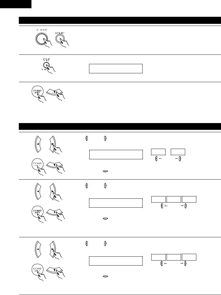
ENGLISH
Before setting up the system
1 |
Check that all the components are correct, then press the POWER operation switch on the main unit or |
the POWER button on the remote control unit to turn on the power. |
|
(Main unit) |
(Remote control unit) |
2
3
Press the SYSTEM SETUP button to enter the setting.
*SYSTEM SET UP
NOTE: Please make sure the “AUDIO” position of the slide switch on the remote control unit.
Press the ENTER or  (down) button to switch to the speaker configuration set up.
NOTE:
Press the SYSTEM SETUP button again to finish system set up. System set up can be finished at any time. The changes to the settings made up to that point are entered.
Setting the speaker configuration
1 |
Use the |
(left) and |
(right) buttons to select your front speaker type. |
|||
|
||||||
|
|
|
|
|
(Initial) |
|
|
|
1 FRONT |
LARGE |
LARGE |
SMALL |
|
|
|
|
|
|||
|
|
|
|
|
(left) button |
(right) button |
|
Press the ENTER or |
(down) button to switch to the center speaker setting. |
||||
2 |
Use the |
(left) and |
(right) buttons to select your center speaker type. |
|||
|
||||||
|
|
|
|
|
|
(Initial) |
|
|
|
|
|
LARGE |
SMALL NONE |
|
|
2 CENTER |
SMALL |
|
|
|
|
|
|
|
|
(left) button (right) button |
|
|
Press the ENTER or |
(down) button to switch to the surround speaker setting. |
||||
NOTE:
• When “Small” has been selected for the front speakers, “Large” cannot be selected for the center speaker.
3 |
Use the (left) and |
(right) buttons to select your surround speaker type. |
|
|
|||
|
|
|
(Initial) |
|
|
|
LARGE SMALL NONE |
|
3 SURR. |
SMALL |
|
|
|
|
(left) button (right) button |
|
Press the ENTER or |
(down) button to switch to the surround back speaker setting. |
|
NOTE:
• When “Small” has been selected for the front speakers, “Large” cannot be selected for the surround speakers.
18
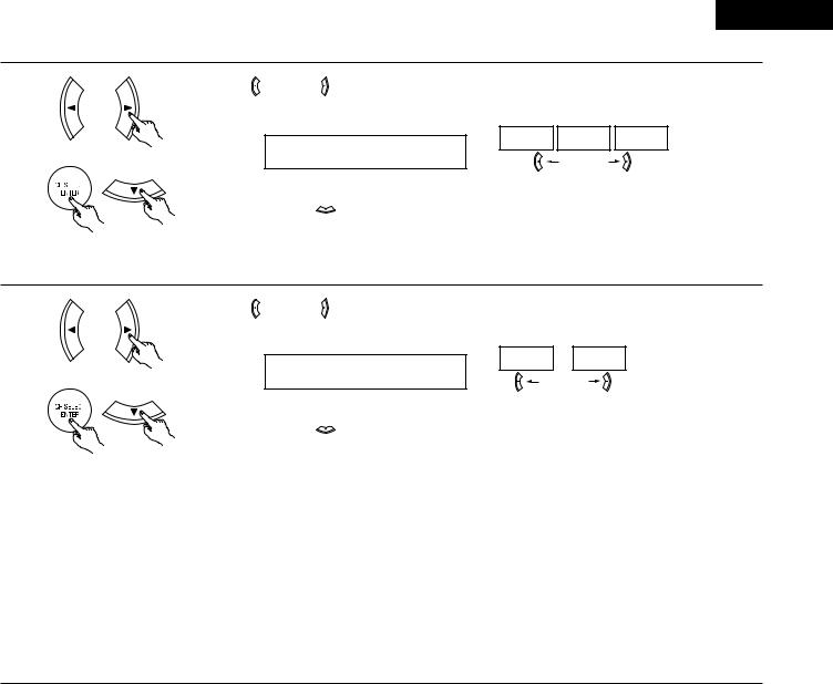
ENGLISH
4 |
Use the (left) and |
(right) buttons to select your surround back speaker type. |
|
||
|
|
(Initial) |
|
|
LARGE SMALL NONE |
|
4 S.BACK SMALL |
|
|
|
(left) button (right) button |
|
Press the ENTER or |
(down) button to switch to the subwoofer setting. |
NOTE:
• When “Small” has been selected for the surround speakers, “Large” cannot be selected for the surround back speakers.
5 |
Use the |
(left) and |
(right) buttons to select your subwoofer setting. |
||
|
|||||
|
|
|
|
(Initial) |
|
|
|
|
|
YES |
NO |
|
|
5 S.WOOFER |
YES |
|
|
|
|
|
|
(left) button |
(right) button |
|
Press the ENTER or |
(down) button to enter the settings and switch to the subwoofer mode setting. |
|||
•Parameters
Large…… Select this when using speakers that can fully reproduce low sounds of below 80 Hz.
Small…… Select this when using speakers that cannot reproduce low sounds of below 80 Hz with sufficient volume. When this setting is selected, low frequencies of below 80 Hz are assigned to the subwoofer.
None…… Select this when no speakers are installed.
Yes/No…. Select “Yes” when a subwoofer is installed, “No” when it’s not installed.
NOTE:
Select “Large” or “Small” not according to the physical size of the speaker, but according to the bass reproduction capacity at 80 Hz. If you cannot determine the best setting, try comparing the sound when set to “Small” and when set to “Large”, at a level that will not damage the speakers.
Caution:
In case the subwoofer is not used, be sure to set “Subwoofer = No”, or the bass sound of front channel is divided to subwoofer channel and not reproduced in some mode.
19
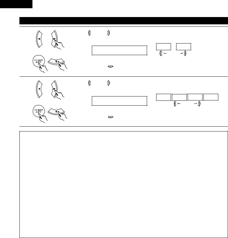
ENGLISH
Setting the Subwoofer mode and Crossover Frequency
1 |
Use the |
(left) and |
(right) buttons to select the Subwoofer mode. |
|
|
|
|
|
|
|
|
|
|
|
|
|
(Initial) |
|
|
|
|
|
|
NORM |
+MAIN |
|
|
|
|
6 SW MODE NORM |
|
|
|
|
|
|
|
(left) button |
(right) button |
|
|
|
Press the ENTER or |
(down) button to enter the setting and switch to the Crossover Frequency |
||||
|
setting. |
|
|
|
|
|
2 |
Use the |
(left) and |
(right) buttons to select the Crossover Frequency. |
|
|
|
|
|
|
|
|
|
|
|
|
|
(Initial) |
|
|
|
|
|
|
80Hz |
100Hz |
120Hz |
150Hz |
|
|
7 CR.OVER 80Hz |
|
|
|
|
|
|
|
(left) button |
(right) button |
||
|
Press the ENTER or |
(down) button to enter the setting and switch to the SPEAKER DISTANCE |
||||
|
setting. |
|
|
|
|
|
NOTES:
— Assignment of low frequency signal range —
• The signals produced from the subwoofer channel are LFE signals (during playback of Dolby Digital or DTS signals) and the low frequency signal range of channels set to “SMALL” in the setup. The low frequency signal range of channels set to “LARGE” are produced from those channels.
— Crossover Frequency —
•When “Subwoofer” is set to “Yes” at the “Speaker Configuration Setting”, set the frequency (Hz) below which the bass sound of the various speakers is to be output from the subwoofer (the crossover frequency).
•For speakers set to “Small”, sound with a frequency below the crossover frequency is cut, and the cut bass sound is output from the subwoofer instead.
NOTE: For ordinary speaker systems, we recommend setting the crossover frequency to 80 Hz. When using small speakers, however, setting the crossover frequency to a high frequency may improve frequency response for frequencies near the crossover frequency.
— Subwoofer mode —
•The subwoofer mode setting is only valid when “LARGE” is set for the front speakers and “YES” is set for the subwoofer in the “Speaker Configuration” settings (see pages 18, 19).
If “SMALL” is set for the front speakers or “NO” is set for the subwoofer, the subwoofer mode setting does not affect playback of low frequency signal range.
•When the “+MAIN” playback mode is selected, the low frequency signal range of channels set to “LARGE” are produced simultaneously from those channels and the subwoofer channel.
In this playback mode, the low frequency range expand more uniformly through the room, but depending on the size and shape of the room, interference may result in a decrease of the actual volume of the low frequency range.
•When the “NORM” playback mode is selected, the low frequency signal range of channels set to “LARGE” are only produced from those channels. In this playback mode there tends to be little interference of the low frequency range in the room.
•Try playing the music or movie source and select the playback mode providing the stronger low frequency range sound.
20
ENGLISH
Setting the delay time
• Input the distance between the listening position and the different speakers to set the delay time for the surround mode.
Preparations:
Measure the distances between the listening position and the speakers (L1 to L5) on the diagram at the right).
L1: Distance between center speaker and listening position L2: Distance between front speakers and listening position L3: Distance between surround speakers and listening position
L4: Distance between surround back speaker and listening position L5: Distance between subwoofer and listening position
CAUTION:

 Please note that the difference for every speaker should be 15 ft or less.
NOTE:
• No setting when “None” has been selected for the Speaker Configuration setting.
FL |
Center |
FR |
Subwoofer |
L1 L2 |
|
Listening position
L5
SL |
L3 |
L4 |
SR |
|
|
|
SB
1 |
Use the |
(left) and |
(right) buttons to set the distance from the front L speaker to the listening position. |
|
8 FRONT L 12ft
2
3
•The number changes in units of 1 foot each time one of the buttons is pressed. Select the value closest to the measured distance.
Press the ENTER or  (down) button to switch to the front R speaker setting.
Use the  (left) and
  (right) buttons to set the distance from the front R speaker to the listening position.
9 FRONT R 12ft
•The number changes in units of 1 foot each time one of the buttons is pressed. Select the value closest to the measured distance.
Press the ENTER or  (down) button to switch to the center speaker setting.
Use the  (left) and
  (right) buttons to set the distance from the center speaker to the listening position.
10 CENTER 12ft
•The number changes in units of 1 foot each time one of the buttons is pressed. Select the value closest to the measured distance.
Press the ENTER or  (down) button to switch to the surround L speakers setting.
21
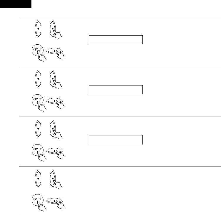
ENGLISH
4
5
6
7
Use the  (left) and
  (right) buttons to set the distance from the surround L speakers to the listening position.
11 SURR.L 10ft
•The number changes in units of 1 foot each time one of the buttons is pressed. Select the value closest to the measured distance.
Press the ENTER or  (down) button to switch to the surround R speaker setting.
Use the  (left) and
  (right) buttons to set the distance from the surround R speakers to the listening position.
12 SURR.R 10ft
•The number changes in units of 1 foot each time one of the buttons is pressed. Select the value closest to the measured distance.
Press the ENTER or  (down) button to switch to the surround back speaker setting.
Use the  (left) and
  (right) buttons to set the distance from the surround back speakers to the listening position.
13 S.BACK 10ft
•The number changes in units of 1 foot each time one of the buttons is pressed. Select the value closest to the measured distance.
Press the ENTER or  (down) button to switch to the subwoofer setting.
Use the  (left) and
  (right) buttons to set the distance from the subwoofer to the listening position.
14 SW |
12ft |
|
|
•The number changes in units of 1 foot each time one of the buttons is pressed. Select the value closest to the measured distance.
Press the ENTER or  (down) button to enter the setting and switch the Test Tone setting.
22
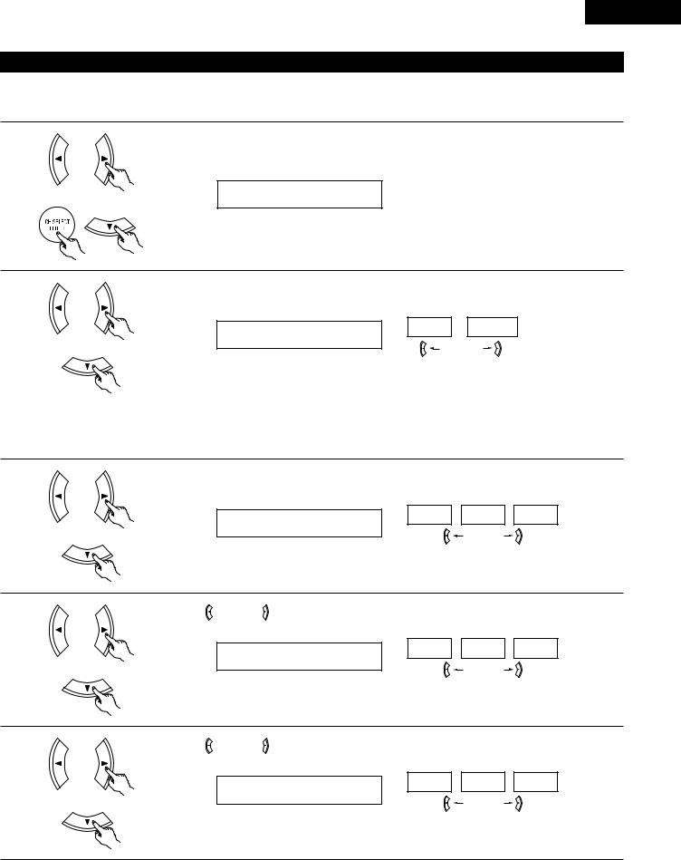
ENGLISH
Setting the Test Tone
•Use this setting to adjust to that the playback level between the different channel is equal.
•From the listening position, listen to the test tones produced from the speakers to adjust the level.
•The level can also be adjusted directly from the remote control unit. (For details, see page 37.)
1
2
3
•Use the  (left) button to switch the Test Tone mode.
•Press the ENTER or  (down) button to switch to the DIGITAL input (COAX) setting.
15 T.TONE <YES
Use the  (left) and
  (right) buttons to select the Test Tone mode. (Initial)
AUTO MANUAL
T.TONE AUTO
(left) button |
(right) button |
Press the  (down) button to start Test Tone.
•Auto:
Adjust the level while listening to the test tones produced automatically from the different speakers.
•Manual:
Select the speaker from which you want to produce the test tone to adjust the level.
Use the  (left) and
  (right) buttons to set the front L channel level. (Initial)
-12dB 0dB +12dB
AUTO-FL
(left) button |
(right) button |
Press the  (down) button to switch to the center channel level (manual mode).
4 |
Use the |
(left) and |
(right) buttons to set the center channel level. |
|
(Initial)
-12dB 0dB +12dB
AUTO-C
(left) button |
(right) button |
Press the  (down) button to switch to the front R channel level (manual mode).
5 |
Use the |
(left) and |
(right) buttons to set the front R channel level. |
|
(Initial)
-12dB 0dB +12dB
AUTO-FR
(left) button |
(right) button |
Press the  (down) button to switch to the surround R channel level (manual mode).
23
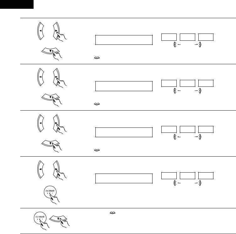
ENGLISH
6
7
8
9
Use the  (left) and
  (right) buttons to set the surround R channel level. (Initial)
-12dB 0dB +12dB
AUTO-SR
|
(left) button |
(right) button |
Press the |
(down) button to switch to the surround back channel level (manual mode). |
|
Use the  (left) and
  (right) buttons to set the surround back channel level. (Initial)
-12dB 0dB +12dB
AUTO-SB
|
(left) button |
(right) button |
Press the |
(down) button to switch to the surround L channel level (manual mode). |
|
Use the  (left) and
  (right) buttons to set the surround L channel level. (Initial)
-12dB 0dB +12dB
AUTO-SL
|
(left) button |
(right) button |
Press the |
(down) button to switch to the subwoofer channel level (manual mode). |
|
Use the  (left) and
  (right) buttons to set the subwoofer channel level. (Initial)
-12dB 0dB +12dB
AUTO-SW
(left) button |
(right) button |
Press the ENTER button to finish the Test Tone.
10 |
Press the ENTER or |
(down) button to switch the DIGITAL input (COAX) setting. |
|
24
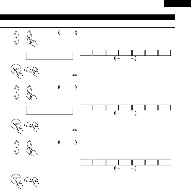
ENGLISH
Setting the Digital In assignment
Input the type of components connected to the digital input terminals.
1 |
Use the |
(left) and |
(right) buttons to assign the input function connected to the COAXIAL input |
||||||
|
|||||||||
|
(COAXIAL) terminal. |
|
|
|
|
|
|
|
|
|
|
|
(Initial) |
|
|
|
|
|
|
|
|
|
CD |
AUX |
DVD |
TV |
VCR |
CDR |
OFF |
|
16 COAX |
CD |
|
|
|
|
|
|
|
|
|
|
|
|
(left) button |
(right) button |
|
|
|
|
• Select “OFF” if nothing is connected. |
|
|
|
|
|
|||
|
Press the ENTER or |
(down) button to switch the optical input 1 (OPT1) setting. |
|
||||||
2 |
Use the |
(left) and |
(right) buttons to assign the input function connected to the OPTICAL input 1 |
||||||
|
|||||||||
|
(OPTICAL 1) terminal. |
|
|
|
|
|
|
|
|
|
|
|
|
|
(Initial) |
|
|
|
|
|
|
|
CD |
AUX |
DVD |
TV |
VCR |
CDR |
OFF |
|
17 OPT1 |
DVD |
|
|
|
|
|
|
|
|
|
|
|
|
(left) button |
(right) button |
|
|
|
|
• Select “OFF” if nothing is connected. |
|
|
|
|
|
|||
|
Press the ENTER or |
(down) button to switch the optical input 2 (OPT2) setting. |
|
||||||
3 |
Use the |
(left) and |
(right) buttons to assign the input function connected to the OPTICAL input 2 |
||||||
|
|||||||||
(OPTICAL 2) terminal.
(Initial)
18 OPT2 |
TV |
|
|
CD |
AUX |
DVD |
TV |
VCR |
CDR |
OFF |
|
|
(left) button |
(right) button |
|
|
|
• Select “OFF” if nothing is connected.
Press the ENTER or  (down) button to switch the auto surround mode setting.
NOTE:
• TUNER, V. AUX cannot be selected.
25
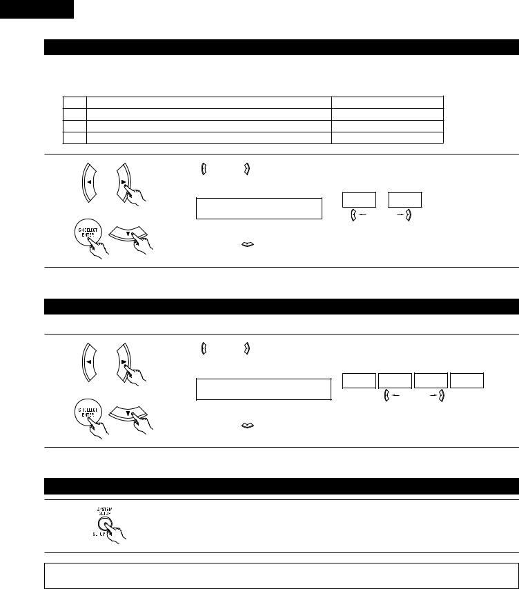
ENGLISH
Setting the Auto Surround Mode
For the three kinds of input signals as shown below, the surround mode played the last is stored in the memory. At next time it the same signal inputs, the memorized surround mode is automatically selected and the signal is played.
Note that the surround mode setting is also stored separately for the different input function.
|
SIGNAL |
|
|
Default Auto Surround Mode |
|
|
q Analog and PCM 2-channel signals |
|
STEREO |
|
|
|
w 2-channel signals of Dolby Digital, DTS or other multichannel format |
Dolby PLII Cinema |
|||
|
e Multichannel signals of Dolby Digital, DTS or other multichannel format |
Dolby or DTS Surround |
|||
1 |
Use the |
(left) and |
(right) buttons to select the Auto Surround mode. |
||
|
|
|
|
|
|
|
|
|
|
(Initial) |
|
|
|
|
|
ON |
OFF |
|
|
19 AUTOSURR. ON |
|
|
|
|
|
|
|
(left) button |
(right) button |
|
Press the ENTER or |
(down) button to switch the Ext. In SW Level setting. |
|||
Setting the Ext. In SW Level
Set the method of playback of the analog input signal connected to the Ext. In terminal.
1 |
Use the (left) and |
(right) buttons to select the Ext. In Subwoofer channel Level playback. |
|||
|
|||||
|
|
|
|
|
(Initial) |
|
|
+00 |
+05 |
+10 |
+15 |
|
20 EXT.IN SW +15 |
|
|
|
|
|
|
(left) button |
(right) button |
||
|
Press the ENTER or |
(down) button if you want to start the settings over from the beginning. |
|||
After setting up the system
1 |
Press the SYSTEM SETUP button to finish system set up. |
|
This completes the system setup operations. Once the system is set up, there is no need to make the settings again unless other components or speakers are connected to or the speaker layout is changed.
26
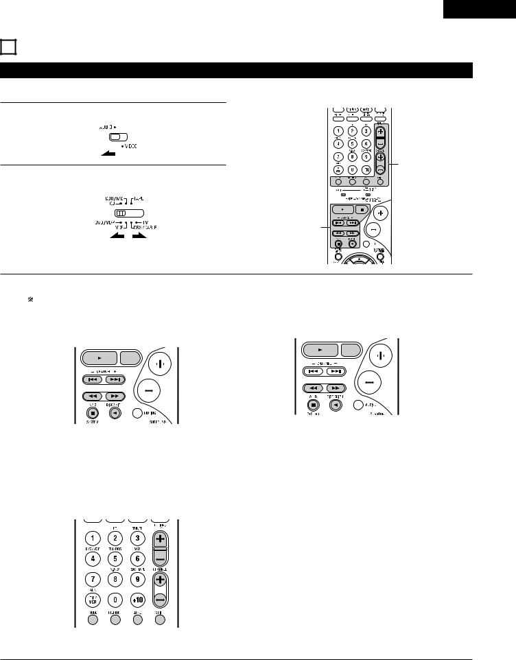
ENGLISH
11 REMOTE CONTROL UNIT
Operating DENON audio components
• Turn on the power of the different components before operating them.
1 |
Set mode switch 1 to “AUDIO”. |
||||||
|
|
|
|
|
|
|
|
|
|
|
|
|
|
|
|
|
|
|
|
|
|
|
|
|
|
|
|
|
|
|
|
3
2 |
Set mode switch 2 to the position for the component to be |
|
operated. (CD, CDR/MD or Tape deck) |
||
|
1 
 2
2
3
3 |
Operate the audio component. |
|
|
|
|
|
• For details, refer to the component’s operating instructions. |
|
|
While this remote control is compatible with a wide range of infrared controlled components, some models of components may not |
|
|
be operated with this remote control. |
|
|
1. CD player (CD) and CD recorder and MD recorder |
2. Tape deck (TAPE) system buttons |
|
(CDR/MD) system buttons |
|
|
|
|
|
|
|
|
|
|
|
|
|
|
|
|
|
|
6 |
: Rewind |
|||
|
|
|
|
|
|
|||||
|
|
|
|
|
|
|||||
6, 7 |
: Manual search (forward and reverse) |
7 |
: Fast-forward |
|||||||
2 |
: Stop |
2 |
: Stop |
|||||||
1 |
: Play |
1 |
: Forward play |
|||||||
8, 9 |
: Auto search (cue) |
0 |
: Reverse play |
|||||||
3 |
: Pause |
A/B |
: Switch between decks A and B |
|||||||
DISC |
: Switch discs |
|
|
|
|
|
||||
SKIP+ |
(for CD changers only) |
|
|
|
|
|
||||
3. Tuner system buttons
SHIFT |
: Switch preset channel range |
CHANNEL |
: Preset channel |
+, – |
up/down |
TUNING |
: Frequency |
+, – |
up/down |
BAND |
: Switch between the AM and FM bands |
MODE |
: Switch between auto and mono |
MEMORY |
: Preset memory |
NOTE:
• TUNER can be operated when the switch is at “AUDIO” position.
27
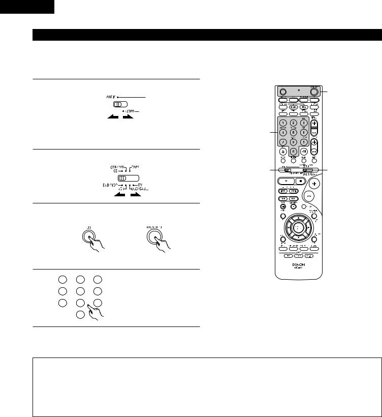
ENGLISH
Preset memory
DENON and other makes of components can be operated by setting the preset memory.
This remote control unit can be used to operate components of other manufacturers without using the learning function by registering the manufacturer of the component as shown on the List of Preset Codes (pages 122~126).
Operation is not possible for some models.
1 Set mode switch 1 to “AUDIO” or “VIDEO”.
3
|
Set the AUDIO side for the CD, Tape deck or CDR/MD |
4 |
|
|
position, to the VIDEO side for the DVD/VDP, DBS/CABLE, |
|
|
|
VCR or TV position. |
|
|
2 |
Set mode switch 2 to the component to be registered. |
1 |
2 |
|
|
||
3 |
Press the ON/SOURCE button and the OFF button at the |
|
|
|
|
|
same time.
• Indicator flash.
4 |
1 |
2 |
3 |
|
|||
|
4 |
5 |
6 |
|
7 |
8 |
9 |
|
|
0 |
|
Referring to the included List of Preset Codes, use the number buttons to input the preset code (a 3-digit number) for the manufacturer of the component whose signals you want to store in the memory.
5 |
To store the codes of another component in the memory, |
|
repeat steps 1 to 4. |
||
|
||
|
|
NOTES:
•The signals for the pressed buttons are emitted while setting the preset memory. To avoid accidental operation, cover the remote control unit’s transmitting window while setting the preset memory.
•Depending on the model and year of manufacture, this function cannot be used for some models, even if they are of makes listed on the included list of preset codes.
•Some manufacturers use more than one type of remote control code. Refer to the included list of preset codes to change the number and check.
•The preset memory can be set for one component only among the following: CDR/MD, DVD/VDP and DBS/CABLE.
The preset codes are as follows upon shipment from the factory and after resetting:
TV, VCR..................................................... |
HITACHI |
CD, TAPE .................................................. |
DENON |
CDR/MD ................................................... |
DENON (CDR) |
DVD/VDP .................................................. |
DENON (DVD) |
DBS/CABLE .............................................. |
ABC (CABLE) |
28
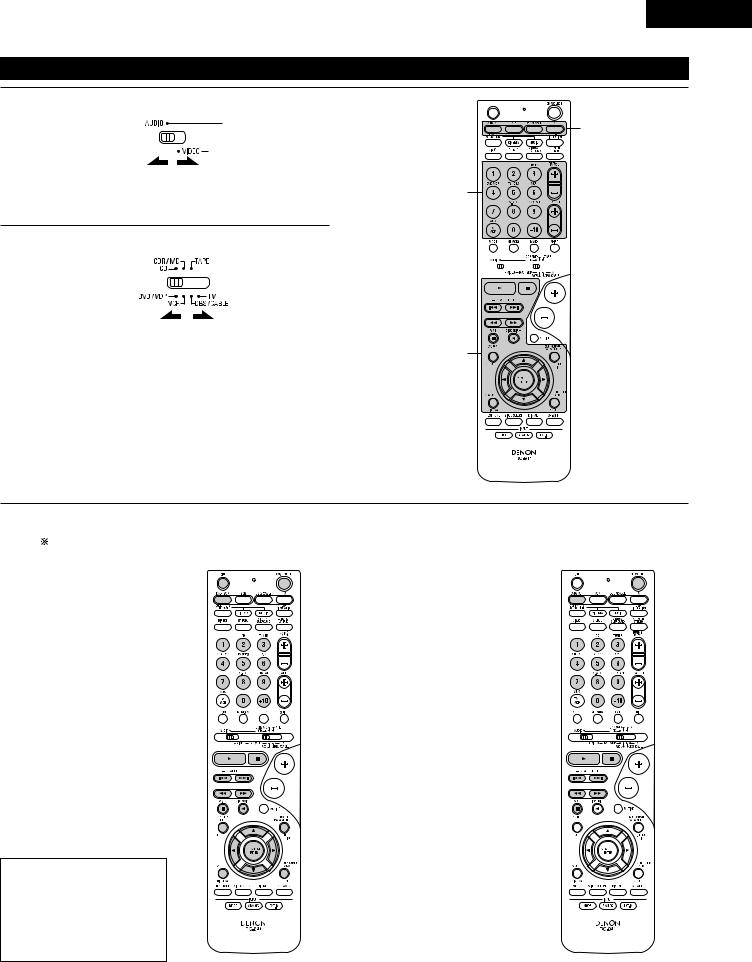
ENGLISH
Operating component stored in the preset memory
1 |
Set mode switch 1 to “AUDIO” or “VIDEO”. |
Set the AUDIO side for the CD, tape deck or CDR/MD position, to the VIDEO side for the DVD/VDP, DBS/CABLE, VCR or TV position.
3
3
2 |
Set mode switch 2 to the component you want to operate. |
1 
 2
2
3
3 |
Operate the component. |
|
|
|
• For details, refer to the component’s operating instructions. |
|
Some models cannot be operated with this remote control unit. |
1.Digital video disc player (DVD, DVD SETUP) system buttons
POWER |
: Power on/standby |
(ON/SOURCE) |
|
OFF |
: DENON DVD power off |
6,7 |
: Manual search |
|
(forward and reverse) |
2 |
: Stop |
1 |
: Play |
8,9 |
: Auto search |
|
(to beginning of track) |
3 |
: Pause |
0 ~ 9, +10 |
: 10 key |
skip + |
: Disc skip |
|
(for DVD changer only) |
DISPLAY |
: Switch display |
MENU |
: Menu |
RETURN |
: Return |
SETUP |
: Setup |
•, ª, 0, 1 |
: Cursor up, down, left |
|
and right |
ENTER |
: Enter setting |
NOTE:
•Some manufacturers use different names for the DVD remote control buttons, so also refer to the instructions on remote control for that component.
2.Video disc player (VDP) system buttons
POWER : Power on/standby (ON/SOURCE)
6,7 : Manual search (forward and reverse)
2: Stop
1: Play
8,9 : Auto search (cue)
3: Pause
0~9, +10 : 10 key
29
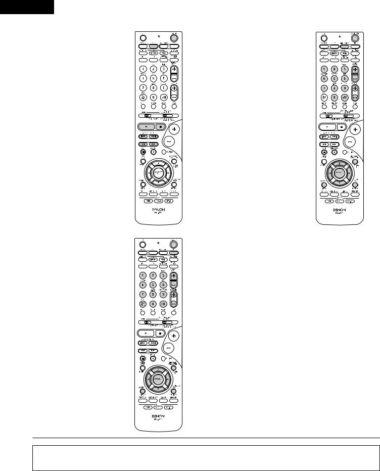
ENGLISH
3.Video deck (VCR) system buttons
POWER |
: Power on/standby |
(ON/SOURCE)
6,7 |
: Manual search |
|
(forward and reverse) |
2 |
: Stop |
1 |
: Play |
3 |
: Pause |
Channel +, – |
: Channels |
5.Monitor TV (TV) system buttons
POWER |
: Power on/standby |
(ON/SOURCE) |
|
MENU |
: Menu |
RETURN |
: Return |
•, ª, 0, 1 |
: Cursor up, down, left |
|
and right |
ENTER |
: Enter |
CHANNEL |
: Switch channels |
+, – |
|
0~9, +10 |
: Channels |
DISPLAY |
: Switch display |
TV/VCR |
: Switch between TV |
|
and video player |
TV VOL |
: Volume up/down |
+, – |
|
4.Digital broadcast satellite (DBS) tuner and cable (CABLE) system buttons
POWER |
: Power on/standby |
(ON/SOURCE) |
|
MENU |
: Menu |
RETURN |
: Return |
•, ª, 0, 1 |
: Cursor up, down, left |
|
and right |
ENTER |
: Enter |
CHANNEL |
: Switch channels |
+, – |
|
0~9, +10 |
: Channels |
DISPLAY |
: Switch display |
VOL +, – |
: Volume up/down |
NOTES:
•For this CD, CDR, MD and TAPE components, buttons can be operated in the same way as for Denon audio components (page 27).
•The TV can be operated when the switch is at DVD/VDP, VCR, TV position.
30
 Loading...