


AV SURROUND AMPLIFIER
AVC-A11XV
OPERATING INSTRUCTIONS
BEDIENUNGSANLEITUNG
MODE D’EMPLOI
ISTRUZIONI PER L’USO
INSTRUCCIONES DE OPERACION
GEBRUIKSAANWIJZING
BRUKSANVISNING
|
|
|
|
SVENSKA |
NEDERLANDS |
ESPAÑOL |
ITALIANO |
FRANCAIS DEUTSCH ENGLISH |
|||||||||||||||||||
|
|
|
|
|
|
|
NOTE ON USE / HINWEISE ZUM GEBRAUCH / |
|
|
|
|
|
|
|
|||||||||||||
|
|
|
CAUTION |
|
|
OBSERVATIONS RELATIVES A L’UTILISATION / NOTE SULL’USO |
|
|
|||||||||||||||||||
|
|
RISK OF ELECTRIC SHOCK |
|
|
NOTAS SOBRE EL USO / ALVORENS TE GEBRUIKEN / OBSERVERA |
||||||||||||||||||||||
|
|
|
DO NOT OPEN |
|
|
|
|
|
|
|
|
|
|
|
|
|
|
|
|
|
|
|
|
|
|
||
CAUTION: TO REDUCE THE RISK OF ELECTRIC SHOCK, DO NOT |
|
|
|
|
|
|
|
|
|
|
|
|
|
|
|
|
|
|
|
|
|
||||||
|
|
REMOVE COVER (OR BACK). NO USER-SERVICEABLE |
|
|
|
|
|
|
|
|
|
|
|
|
|
|
|
|
|
|
|
|
|
||||
|
|
PARTS INSIDE. REFER SERVICING TO QUALIFIED |
|
|
|
|
|
|
|
|
|
|
|
|
|
|
|
|
|
|
|
|
|
||||
|
|
SERVICE PERSONNEL. |
|
|
|
|
|
• Keep the set free from moisture, water, and |
• Do not let foreign objects in the set. |
|
|
||||||||||||||||
|
|
The lightning flash with arrowhead symbol, within an equilateral triangle, |
|
|
|
|
• Keine fremden Gegenstände in das Gerät |
||||||||||||||||||||
|
|
|
|
|
|
dust. |
|
|
|
|
|
|
|
|
|
kommen lassen. |
|
|
|
|
|||||||
|
|
is intended to alert the user to the presence of uninsulated “dangerous |
|
|
|
|
• Halten |
Sie |
das |
Gerät |
von Feuchtigkeit, |
• Ne pas laisser des objets étrangers dans |
|||||||||||||||
|
|
|
• Avoid high temperatures. |
|
Wasser und Staub fern. |
|
|
|
|
l’appareil. |
|
|
|
|
|
|
|||||||||||
|
|
voltage” within |
the product’s enclosure that may be of sufficient |
|
|
|
|
|
|
|
|
|
|
|
|
||||||||||||
|
|
|
|
• Protéger l’appareil contre l’humidité, l’eau |
• E’ importante che nessun oggetto è inserito |
||||||||||||||||||||||
|
|
|
Allow for sufficient heat dispersion when |
||||||||||||||||||||||||
|
|
magnitude to constitute a risk of electric shock to persons. |
|
|
et lapoussière. |
|
|
|
|
|
|
all’interno dell’unità. |
|
|
|
||||||||||||
|
|
|
|
installed on a rack. |
|
|
|
|
|
|
|
|
|
|
|||||||||||||
|
|
|
|
|
• Tenete |
l’unità |
|
lontana |
dall’umidità, |
• No deje objetos extraños dentro del equipo. |
|||||||||||||||||
|
|
|
|
|
|
|
• Vermeiden Sie hohe Temperaturen. |
|
|||||||||||||||||||
|
|
|
|
|
|
|
dall’acqua e dalla polvere. |
|
|
|
• Laat geen |
vreemde voorwerpen |
in |
dit |
|||||||||||||
|
|
|
|
|
|
|
Beachten Sie, |
daß eine |
ausreichend |
|
|
|
|||||||||||||||
|
|
The exclamation point within an equilateral triangle is intended to alert the |
|
• Mantenga el equipo libre de humedad, agua |
apparaat vallen. |
|
|
|
|
||||||||||||||||||
|
|
|
Luftzirkulation gewährleistet |
wird, wenn |
|
|
|
|
|||||||||||||||||||
|
|
|
y polvo. |
|
|
|
|
|
|
|
|
• Se till att främmande föremål inte tränger in |
|||||||||||||||
|
|
user to the presence of important operating and maintenance (servicing) |
|
das Gerät auf ein Regal gestellt wird. |
|
|
|
|
|
|
|
|
|||||||||||||||
|
|
|
• Laat geen vochtigheid, water of stof in het |
i apparaten. |
|
|
|
|
|
||||||||||||||||||
|
|
|
• Eviter des températures élevées |
|
|
|
|
|
|||||||||||||||||||
|
|
instructions in the literature accompanying the appliance. |
|
|
Tenir compte d’une dispersion de chaleur |
apparaat binnendringen. |
|
|
|
|
|
|
|
|
|
|
|
||||||||||
|
|
|
|
• Utsätt inte apparaten för fukt, vatten och |
|
|
|
|
|
|
|
||||||||||||||||
|
|
|
|
|
|
|
suffisante lors |
de l’installation sur une |
damm. |
|
|
|
|
|
|
|
|
|
|
|
|
|
|
|
|
||
|
|
|
|
|
|
|
étagère. |
|
|
|
|
|
|
|
|
|
|
|
|
|
|
|
|
|
|
||
WARNING: TO REDUCE THE RISK OF FIRE OR ELECTRIC SHOCK, DO |
|
|
|
|
|
|
|
|
|
|
|
|
|
|
|
|
|
|
|
|
|||||||
|
• Evitate di esporre l’unità a temperature alte. |
|
|
|
|
|
|
|
|
|
|
|
|
|
|
|
|
|
|||||||||
|
Assicuratevi che ci sia un’adeguata |
|
|
|
|
|
|
|
|
|
|
|
|
|
|
|
|
|
|||||||||
|
|
NOT EXPOSE THIS APPLIANCE TO RAIN OR MOISTURE. |
|
dispersione del |
calore quando installate |
|
|
|
|
|
|
|
|
|
|
|
|
|
|
|
|
|
|||||
|
|
|
l’unità in un mobile per componenti audio. |
|
|
|
|
|
|
|
|
|
|
|
|
|
|
|
|
|
|||||||
|
|
|
|
|
|
|
|
|
|
|
|
|
|
|
|
|
|
|
|
|
|
|
|
||||
|
|
|
|
|
|
|
• Evite altas temperaturas |
|
|
|
|
|
|
|
|
|
|
|
|
|
|
|
|
|
|
||
|
|
|
|
|
|
|
Permite la suficiente dispersión del calor |
|
|
|
|
|
|
|
|
|
|
• Do not |
let |
insecticides, |
benzene, |
and |
|||||
|
|
|
|
|
|
|
cuando está instalado en la consola. |
|
|
|
|
|
|
|
|
|
|
||||||||||
|
|
|
|
|
|
|
|
|
|
|
|
|
|
|
|
|
thinner come in contact with the set. |
|
|
||||||||
• DECLARATION OF CONFORMITY |
|
• DECLARACIÓN DE CONFORMIDAD |
|
• Vermijd hoge temperaturen. |
|
|
|
|
|
|
|
|
|
|
|
|
|
||||||||||
|
|
|
• Unplug the power cord when not using the |
• Lassen Sie das Gerät nicht mit Insektiziden, |
|||||||||||||||||||||||
|
|
Zorg voor een degelijk hitteafvoer indien het |
|||||||||||||||||||||||||
We declare under our sole responsibility that this |
Declaramos bajo nuestra exclusiva responsabilidad |
set for long periods of time. |
|
|
|
Benzin |
oder |
Verdünnungsmitteln |
in |
||||||||||||||||||
apparaat op een rek wordt geplaatst. |
|
Zeit |
nicht |
||||||||||||||||||||||||
product, to |
which |
this declaration relates, is in |
que este producto al que hace |
referencia |
esta |
• Undvik höga temperaturer. |
|
• Wenn |
das |
Gerät eine |
längere |
Berührung kommen. |
|
|
|
||||||||||||
|
verwendet |
werden |
soll, trennen Sie das |
• Ne pas mettre en contact des insecticides, |
|||||||||||||||||||||||
Se till att det |
finns möjlighet till god |
||||||||||||||||||||||||||
conformity with the following standards: |
declaración, está conforme con |
los siguientes |
Netzkabel vom Netzstecker. |
|
|
|
du benzène et un diluant avec l’appareil. |
||||||||||||||||||||
värmeavledning vid montering i ett rack. |
|
|
|
||||||||||||||||||||||||
EN60065, EN55013, EN55020, EN61000-3-2 and |
estándares: |
|
|
• Débrancher |
|
le |
cordon |
d’alimentation |
• Assicuratevvi che l’unità non venga in |
||||||||||||||||||
|
|
|
|
|
|
||||||||||||||||||||||
EN61000-3-3. |
|
|
EN60065, EN55013, EN55020, EN61000-3-2 y |
|
|
|
lorsque l’appareil n’est pas utilisé pendant |
contatto con insetticidi, benzolo o solventi. |
|||||||||||||||||||
|
|
|
|
|
de longues périodes. |
|
|
|
|
• No permita el contacto de insecticidas, |
|||||||||||||||||
Following the provisions of 73/23/EEC, 89/336/EEC |
EN61000-3-3. |
|
|
|
|
|
• Disinnestate il filo di alimentazione quando |
gasolina y diluyentes con el equipo. |
|
|
|||||||||||||||||
and 93/68/EEC Directive. |
|
Siguiendo las provisiones de |
las Directivas |
|
|
|
avete l’intenzione di non usare il filo di |
• Laat geen insektenverdelgende middelen, |
|||||||||||||||||||
• ÜBEREINSTIMMUNGSERKLÄRUNG |
|
73/23/EEC, 89/336/EEC y 93/68/EEC. |
|
|
|
|
alimentazione |
per |
un |
lungo |
periodo di |
benzine of verfverdunner met dit apparaat |
|||||||||||||||
|
|
|
|
|
tempo. |
|
|
|
|
|
|
|
|
|
in kontakt komen. |
|
|
|
|||||||||
|
|
|
|
|
|
|
|
|
|
|
|
|
|
|
|
|
|
|
|||||||||
Wir erklären unter unserer Verantwortung, daß |
• EENVORMIGHEIDSVERKLARING |
|
|
|
|
• Desconecte el cordón de energía cuando no |
• Se till att inte insektsmedel på spraybruk, |
||||||||||||||||||||
dieses Produkt, auf das sich diese Erklärung |
Wij verklaren uitsluitend op onze verantwoordelijkheid |
|
|
|
utilice el equipo por mucho tiempo. |
|
bensen och thinner kommer i kontakt med |
||||||||||||||||||||
|
|
|
• Neem |
altijd |
|
het |
netsnoer |
uit |
het |
apparatens hölje. |
|
|
|
|
|||||||||||||
bezieht, den folgenden Standards entspricht: |
dat dit produkt, waarop deze verklaring betrekking |
|
|
|
stopkontakt |
wanneer |
het |
apparaat |
|
|
|
|
|
|
|
||||||||||||
EN60065, EN55013, EN55020, EN61000-3-2 und |
heeft, in overeenstemming is met de volgende |
• Handle the power cord carefully. |
gedurende |
een |
lange periode |
niet |
wordt |
|
|
|
|
|
|
|
|||||||||||||
gebruikt. |
|
|
|
|
|
|
|
|
|
|
|
|
|
|
|
||||||||||||
EN61000-3-3. |
|
|
normen: |
|
|
|
|
|
|
|
|
|
|
|
|
|
|
|
|
|
|||||||
|
|
|
|
Hold the plug when unplugging the cord. |
• Koppla ur nätkabeln om apparaten inte |
|
|
|
|
|
|
|
|||||||||||||||
Entspricht |
den |
Verordnungen der |
Direktive |
EN60065, EN55013, EN55020, EN61000-3-2 en |
• Gehen Sie vorsichtig mit dem Netzkabel |
kommer att användas i lång tid. |
|
|
|
|
|
|
|
|
|
||||||||||||
73/23/EEC, 89/336/EEC und 93/68/EEC. |
EN61000-3-3. |
|
|
um. |
|
|
|
|
|
|
|
|
|
|
|
|
|
|
|
|
|
|
|
||||
|
|
Halten Sie das Kabel am Stecker, wenn Sie |
|
|
|
|
|
|
|
|
|
|
|
|
|
|
|
|
|
||||||||
• DECLARATION DE CONFORMITE |
|
Volgens de bepalingen van de Richtlijnen 73/23/EEC, |
den Stecker herausziehen. |
|
|
|
|
|
|
|
|
|
|
|
|
|
|
|
|
|
|
||||||
|
89/336/EEC en 93/68/EEC. |
|
|
• Manipuler le cordon d’alimentation avec |
|
|
|
|
|
|
|
|
|
|
|
|
|
|
|
|
|
||||||
Nous déclarons sous notre seule responsabilité |
|
|
|
|
|
|
|
|
|
|
|
|
• Never disassemble or modify the set in any |
||||||||||||||
• ÖVERENSSTÄMMELSESINTYG |
|
|
précaution. |
|
|
|
|
|
|
|
|
|
|
|
|
||||||||||||
que l’appareil, auquel se réfère cette déclaration, |
|
|
Tenir la prise lors du débranchement du |
|
|
|
|
|
|
|
|
|
|
way. |
|
|
|
|
|
|
|||||||
est conforme aux standards suivants: |
|
Härmed intygas helt på eget ansvar att denna |
cordon. |
|
|
|
|
|
|
|
|
|
|
|
|
• Versuchen |
Sie |
niemals |
das |
Gerät |
|||||||
EN60065, EN55013, EN55020, EN61000-3-2 et |
produkt, vilken detta intyg avser, uppfyller följande |
• Manneggiate il filo di alimentazione con |
|
|
|
|
|
|
|
|
|
|
auseinander zu nehmen oder auf jegliche |
||||||||||||||
cura. |
|
|
* (For sets with ventilation holes) |
|
Art zu verändern. |
|
|
|
|
||||||||||||||||||
EN61000-3-3. |
|
|
standarder: |
|
|
Agite per la spina quando scollegate il cavo |
• Do not obstruct the ventilation holes. |
|
• Ne jamais démonter ou modifier l’appareil |
||||||||||||||||||
D’après les dispositions de la Directive 73/23/EEC, |
EN60065, EN55013, EN55020, EN61000-3-2 och |
dalla presa. |
|
|
nicht |
d’une manière ou d’une autre. |
|
|
|||||||||||||||||||
89/336/EEC et 93/68/EEC. |
|
EN61000-3-3. |
|
|
• Maneje el cordón de energía con cuidado. |
• Die Belüftungsöffnungen |
dürfen |
• Non smontate mai, nè modificate l’unità in |
|||||||||||||||||||
|
|
|
Sostenga el enchufe cuando desconecte el |
verdeckt werden. |
|
|
|
|
|
nessun modo. |
|
|
|
|
|||||||||||||
• DICHIARAZIONE DI CONFORMITÀ |
|
Enligt stadgarna i direktiv 73/23/EEC, 89/336/EEC |
cordón de energía. |
|
• Ne pas obstruer les trous d’aération. |
|
• Nunca desarme o modifique el equipo de |
||||||||||||||||||||
|
och 93/68/EEC. |
|
|
• Hanteer het netsnoer voorzichtig. |
• Non coprite i fori di ventilazione. |
|
|
ninguna manera. |
|
|
|
|
|||||||||||||||
Dichiariamo con piena responsabilità che questo |
|
|
|
|
|
|
|
|
|||||||||||||||||||
|
|
|
Houd het snoer bij de stekker vast wanneer |
• No obstruya los orificios de ventilación. |
• Nooit dit apparaat demonteren of op andere |
||||||||||||||||||||||
prodotto, al quale la nostra dichiarazione si riferisce, |
|
|
|
deze moet worden aanof losgekoppeld. |
• De ventilatieopeningen mogen niet worden |
wijze modifiëren. |
|
|
|
|
|||||||||||||||||
è conforme alle seguenti normative: |
|
|
|
|
• Hantera nätkabeln varsamt. |
|
beblokkeerd. |
|
|
|
|
|
|
|
• Ta inte isär apparaten och försök inte bygga |
||||||||||||
|
|
|
|
Håll i kabeln när den kopplas från el-uttaget. |
• Täpp inte till ventilationsöppningarna. |
|
om den. |
|
|
|
|
|
|
||||||||||||||
EN60065, EN55013, EN55020, EN61000-3-2 e |
|
|
|
|
|
|
|
|
|
|
|||||||||||||||||
|
|
|
|
|
|
|
|
|
|
|
|
|
|
|
|
|
|
|
|
|
|
|
|||||
EN61000-3-3. |
|
|
|
|
|
CAUTION |
|
|
|
|
|
|
|
|
|
|
|
|
|
|
|
|
|
|
|||
In conformità con le condizioni delle direttive |
|
|
|
|
|
|
|
|
|
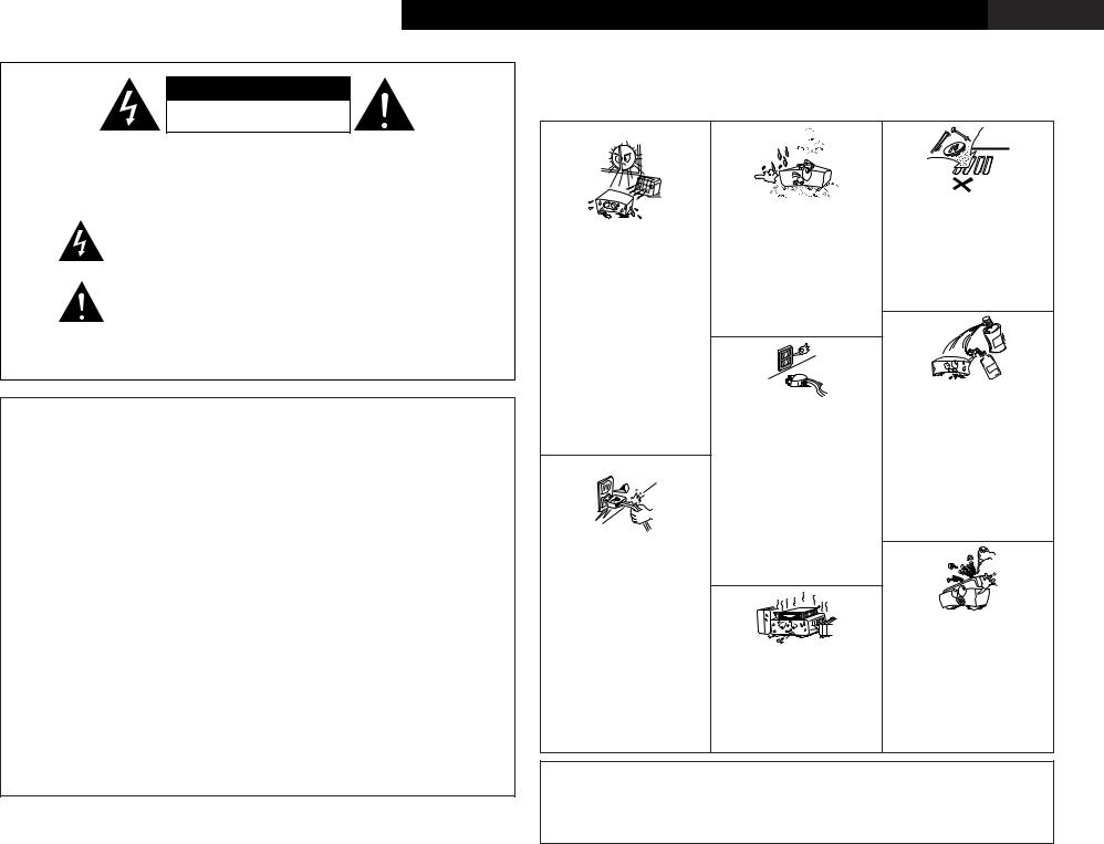
• Please be care the environmental aspects |
of |
||||||||||||||||
73/23/EEC, 89/336/EEC e 93/68/EEC. |
|
|
|
|
• The ventilation should not be impeded by covering |
|
battery disposal. |
|
|
|
|
|
|
||||||||||||||
|
|
|
|
|
|
|
the ventilation openings with |
items, |
such |
as |
• The apparatus shall not be exposed to dripping or |
||||||||||||||||
|
|
|
|
|
|
|
newspapers, table-cloths, curtains, etc. |
|
|
|
|
|
splashing for use. |
|
|
|
|
|
|
||||||||
|
|
|
|
|
|
|
• No naked flame sources, such as lighted candles, |
• No objects filled with liquids, such as vases, shall |
|||||||||||||||||||
|
|
|
|
|
|
|
should be placed on the apparatus. |
|
|
|
|
|
be placed on the apparatus. |
|
|
|
|
||||||||||

ENGLISH DEUTSCH FRANCAIS ITALIANO ESPAÑOL NEDERLANDS SVENSKA
2 System setup menu / Systemsetup-Menü/ Menu de configuration système / Menu di configurazione del sistema / Menú System Setup / System Setup-menu / Systeminställningsmeny
CH
CH SEL |
page 47 |
ENTER |
|
|
page 47 |
|
page 47 |
|
page 48 |
CH SEL
ENTER
CH SEL
ENTER
CH SEL
ENTER
 page 8 ~11


 page 57

 page 58
 page 58
  page 58

 page 53


 page 53, 54
 page 54
 page 54, 55
 page 55, 56
 page 56
  page 56, 57


 page 42


 page 42
 page 43
 page 43
 page 43, 44
  page 44
CH SEL
ENTER
 page 49


 page 49, 50

 page 50
 page 51
 page 51
 page 52
  page 52
CH SEL
ENTER
 page 44, 45


 page 45

 page 45
 page 46
 page 46
  page 46
ENGLISH
Getting Started
Contents
Getting Started
Accessories ·····························································2
Before using····························································2
Cautions on installation ········································2
Cautions on handling·············································2
Preparing the remote control unit ·······················2
Inserting the batteries ···········································3
Operating range of the remote control unit ·······3
Part names and functions
Front panel ····························································3
Display···································································4 Remote control unit ··············································4
Easy Setup and Operation
Easy to setup flow ·················································5
Speaker system layout ··········································5
Speaker connections ·············································6
Connecting a DVD player and monitor TV··········7
Auto Setup / Room EQ··········································8
Connecting a microphone ·····································8
Turning on the power ············································9
Starting Auto Setup···············································9 Extra Setup····························································9 Preliminary measurements ·····························9, 10 Speaker system measurement ···························10
Check of the measurement result ······················11
About the error message ····································11
Playing a DVD with surround sound ·················11
Connecting Other Sources
Cable indications··················································12
The video conversion function ···························12
On screen display for component video outputs and HDMI output··················································13
Connecting equipment with HDMI (High-Definition Multimedia Interface) terminals [To convert analog video signals
to HDMI signals]···················································13
Connecting a TV tuner ········································13
Connecting a DBS tuner······································13
Connecting the external inputs
(EXT. IN) terminals ···············································14
Connecting a video camera component
or video game component··································14
Connecting a DVD recorder ································14
Connecting a VCR ················································15
Connecting a CD player·······································15
Connecting a turntable········································15
Connecting a CD recorder or MD recorder········15
Connecting a tape deck·······································16
DENON LINK connections ···································16
Connecting equipment with HDMI (High Definition Multimedia Interface)
terminals ·······························································16
Connecting equipment with DVI
(Digital Visual Interface) terminals·····················17
Connecting IEEE1394 devices ·····························17
Connecting the CONTROL terminals ·················18
Connecting the TRIGGER OUT terminals ··········18
Connecting the MULTI ZONE terminals
ZONE2 (or ZONE3) pre-out connections·············18 ZONE2 / ZONE3 speaker out connections ·········19
Connecting the pre-out terminals ······················19
Connecting the power supply cord····················19
Basic Operation
Playback
Operating the remote control unit ······················20
Playing the input source······································20 Playback using the external input
(EXT. IN) terminals···············································21 Turning the sound off temporarily (MUTING)······21 Listening over headphone···································21 Combining the currently playing sound
with the desired image (VIDEO SELECT) ···········21
Switching the surround speakers························21 Checking the currently playing
program source, etc. ···········································21
Input mode····················································21, 22 Room EQ function···············································22
Surround
Playing modes for different sources ···················23
Playing audio sources (CDs and DVDs)
2-channel playback modes ··································24
THX surround EX / Home THX cinema mode
•Playing sources recorded in Dolby Surround in the Home THX cinema
surround mode ··············································24
•To play in the THX surround EX / Home THX cinema surround mode
for sources recorded in Dolby Digital
or DTS ···························································25
Dolby Digital mode and DTS surround················26 Dolby Pro Logic IIx (Dolby Pro Logic II) mode ··27 DTS NEO:6 mode················································28 The Dolby Headphone·········································28 Memory and call-out functions
(USER MODE function)·······································29
DENON original surround modes
Surround modes and their features ····················29
DSP surround simulation·····································30 Tone control setting
•Adjusting the tone ·········································31
•Tone defeat mode ·········································31
Channel level·······················································31 Fader function ·····················································32
Advanced Operation
Remote control unit
Operating DENON audio components··········32, 33 Preset memory ·············································33, 34 Operating a component stored
in the preset memory ···································34, 35 Learning function ················································35
System call····················································35, 36 Punch through·····················································36 Setting the back light’s lighting time···················36 Setting the brightness·········································36 Resetting······················································36, 37
Multi zone music entertainment system ········37
Multi-zone playback using the ZONE2
and ZONE3 PREOUT terminals···························37 Multi-zone playback using
the SPEAKER terminals ······································38
Outputting a program source to an amplifier, etc., in a ZONE2 room
(ZONE2 SELECT mode) ······································38
Outputting a program source to an amplifier, etc., in a ZONE3 room
(ZONE3 SELECT mode) ······································38
Remote control unit operations
during multi-source playback·······························39
Other function
Playing Super Audio CDs
with an IEEE1394 cable ······································39
Multi-source recording / playback
•Playing one source while recording another (REC OUT mode)···········································40
•Recording Dolby Digital
and DTS multi channel sources·····················40
•Dolby Headphone recording··························40 Last function memory ·········································40
Initialization of the microprocessor ·····················40
Advanced Setup – Part 1
Navigating through the System Setup Menu···41
On screen display and front display ··················41
Audio Input Setup
Setting the Digital In Assignment ·······················42
Setting the DENON LINK ····································42
Setting the EXT. IN Setup ···································42
Setting the Input Function Level·························43 Setting the Function Rename ·····························43
Setting the IEEE1394 Assign ························43, 44 Setting the IEEE1394 Auto Function ··················44
1
Getting Started
Video Setup
Setting the HDMI/DVI In Assign ···················44, 45 Setting the Component In Assign·······················45 Setting the Video Convert Mode ························45
Setting the HDMI Out Setup ······························46
Setting the Audio Delay ······································46
Setting the On Screen Display (OSD) ·················46
Advanced Playback
Setting the 2ch Direct / Stereo ···························47
Setting the Dolby Digital Setup···························47 Setting the Auto Surround Mode··················47, 48 Setting the Manual EQ Setup ·····························48
Procedure for copying the “Flat”
correction curve ··················································48
Option Setup
Setting the Channel Setup ··································49
Setting the Power Amplifier Assignment ·····49, 50 Setting the Volume Control·································50 Setting the Trigger Out········································51 ZONE2 and ZONE3 tone control and
channel level setting ···········································51
Setting the Digital Out Assignment ···················52
User Memory ······················································52
Setup Lock ··························································52
Advanced Setup – Part 2
Speaker Setup
Setting the type of speakers·······························53 Setting the low frequency distribution··········53, 54 Setting the Delay Time········································54 Setting the Channel Level·····························54, 55 Setting the Crossover Frequency ·················55, 56 Setting the crossover frequency individually
for the different channels····································56 Selecting the surround speakers
for the different surround modes························56 Settings for using a THX Ultra2
compatible subwoofer ··································56, 57 Surround back speaker position settings ············57
Others Setup
Setting the Room EQ Setup ·······························57
Setting the Direct Mode Setup ···························58
Setting the MIC Input Select ······························58
Check the parameter···········································58
System setup items
and default values ·······································59 ~ 61
Troubleshooting ···················································62
Additional information································63 ~ 75
Specifications ·······················································76
ENGLISH
Getting Started
Thank you for choosing the DENON AVC-A11XV Digital Surround A / V amplifier. This remarkable component has been engineered to provide superb surround sound listening with home theater sources such as DVD, as well as providing outstanding high fidelity reproduction of your favorite music sources.
As this product is provided with an immense array of features, we recommend that before you begin hookup and operation that you review the contents of this manual before proceeding.
Accessories
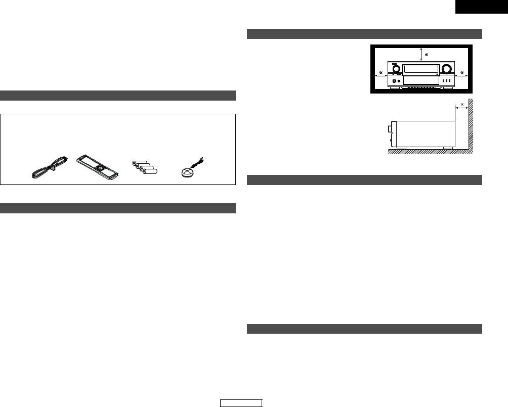
• Check that the following parts are included in addition to the main unit:
q Operating instructions....................................... |
|
1 |
t R03/AAA alkaline batteries ............................... |
4 |
w Service station list............................................. |
|
1 |
y Omnidirectional microphone............................. |
1 |
e Power supply cord ............................................ |
|
1 |
u List of preset codes .......................................... |
1 |
r Remote control unit (RC-995) ........................... |
|
1 |
|
|
e |
r |
|
t |
y |
Before using
Pay attention to the following before using this unit:
•Moving the set
To prevent short circuits or damaged wires in the connection cords, always unplug the power supply cord and disconnect the connection cords between all other audio components when moving the set.
•Store these instructions in a safe place.
After reading, store these instructions along with the warranty in a safe place.
•Note that the illustrations in these instructions may differ from the actual set for explanation purposes.
•Before turning the Power switch on
Check once again that all connections are proper and that there are not problems with the connection cords. Always set the power switch to the standby position before connecting and disconnecting connection cords.
|
ENGLISH |
|
|
Getting Started |
|
Cautions on installation |
|
|
Noise or disturbance of the picture may be generated |
|
|
if this unit or any other electronic equipment using |
Note |
|
microprocessors is used near a tuner or TV. |
||
|
||
If this happens, take the following steps: |
|
|
• Install this unit as far as possible from the tuner or |
|
|
TV. |
|
|
• Set the antenna wires from the tuner or TV away |
|
|
from this unit’s power supply cord and input/output |
|
|
connection cords. |
|
|
• Noise or disturbance tends to occur particularly |
|
|
when using indoor antennas or 300 Ω /ohms feeder |
|
|
wires. We recommend using outdoor antennas |
|
|
and 75 Ω /ohms coaxial cables. |
|
|
Note: |
Wall |
|
For heat dispersal, do not install this equipment in |
||
|
||
a confined space such as a book case or similar |
|
|
unit. |
|
Cautions on handling
•Switching the input function when input terminals are not connected.
A clicking noise may be produced if the input function is switched when nothing is connected to the input terminals. If this happens, either turn down the MASTER VOLUME control knob or connect components to the input terminals.
•Muting of PRE OUT terminals and SPEAKER terminals.
•Whenever the power switch is in the STANDBY state, the apparatus is still connected on AC line voltage.
Please be sure to turn off the power switch or unplug the cord when you leave home for, say, a vacation.
The PRE OUT terminals and SPEAKER terminals include a muting circuit. Because of this, the output signals are greatly reduced for several seconds after the power switch is turned on or input function, surround mode or any other-set-up is changed. If the volume is turned up during this time, the output will be very high after the muting circuit stops functioning. Always wait until the muting circuit turns off before adjusting the volume.
Preparing the remote control unit
The included remote control unit (RC-995) can be used to operate not only the AVC-A11XV but other remote control compatible DENON components as well. In addition, the memory contains the control signals for other remote control units, so it can be used to operate non-DENON remote control compatible products.
2
ENGLISH
ENGLISH
Getting Started
Inserting the batteries
q Remove the remote control unit’s rear cover.
wSet four R03/AAA batteries in the battery compartment in the indicated direction.
e Put the rear cover back on.
Notes on Batteries:
•Replace the batteries with new ones if the set does not operate even when the remote control unit is operated nearby the set. (The included battery is only for verifying operation.)
•When inserting the batteries, be sure to do so in the proper direction, following the “<” and “>” marks in the battery compartment.
•To prevent damage or leakage of battery fluid:
•Do not use a new battery together with an old one.
•Do not use two different types of batteries.
•Do not short-circuit, disassemble, heat or dispose of batteries in flames.
•If the battery fluid should leak, carefully wipe the fluid off the inside of the battery compartment and insert new batteries.
•When replacing the batteries, have the new batteries ready and insert them as quickly as possible.
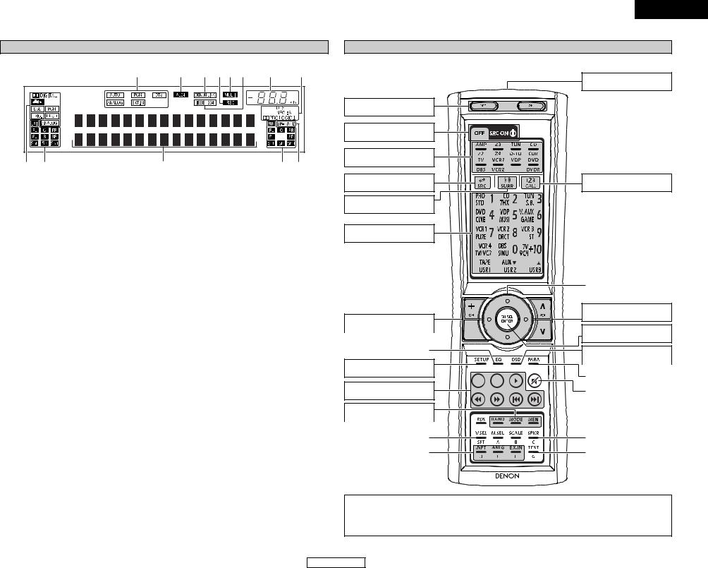
2 Motion sensor
The RC-995 remote control is equipped with a motion sensor that activates the backlighting function when it is picked up and/or handled. Occasionally, you might hear a faint “clicking” sound from within, this is the motion sensor, and is a normal condition.
Operating range of the remote control unit
•Point the remote control unit at the remote sensor on the main unit as shown on the diagram.
•The remote control unit can be used from a straight distance of approximately 7 meters from the main unit, but this distance will be shorter if there are obstacles in the way or if the remote control unit is not pointed directly at the remote sensor.
•The remote control unit can be operated at a horizontal angle of up to 30 degrees with respect to the remote sensor.

 30° 30°
Approx. 7 m
NOTE:
•It may be difficult to operate the remote control unit if the remote sensor is exposed to direct sunlight or strong artificial light.
•Do not press buttons on the main unit and remote control unit simultaneously. Doing so may result in malfunction.
•Neon signs or other devices emitting pulse-type noise nearby may result in malfunction, so keep the set as far away from such devices as possible.
Getting Started
Part names and functions
Front panel
For details on the functions of these parts, refer to the pages given in parentheses ( ).
!5 |
!4 |
!3 |
|
!2!1 |
!0 |
!6 ! !8 |
!9@0@1@2@3@ @ @@@8@9#0#1 |
|
|||
|
#####2 |
|
|
|
|
q w e |
r |
|
t |
y |
u i o |
q Power ON/STANDBY switch .......................... |
(9) |
w Power indicator................................................ |
(9) |
e Power switch ............................................. |
(9, 40) |
r Headphones jack (PHONES) ......................... |
(21) |
t V. AUX INPUT terminals ............................... |
(14) |
y SETUP MIC jack ............................................... |
(8) |
u USER MODE 1 button ................................... |
(29) |
i USER MODE 2 button ................................... |
(29) |
o USER MODE 3 button ................................... |
(29) |
!0MASTER VOLUME control knob .................. |
(20) |
!1MultEQ XT indicator...................................... |
(22) |
!2Master volume indicator............................... |
(20) |
!3Display .............................................................. |
(4) |
!4Remote control sensor.................................... |
(3) |
!5FUNCTION knob ................................ |
(20, 38, 40) |
!6SOURCE button ............................................. |
(20) |
!7ZONE2 SELECT button.................................. |
(38) |
!8ZONE3/REC SELECT button ................... |
(38, 40) |
!9PURE DIRECT button..................................... |
(24) |
@0DIRECT/STEREO button................................ |
(24) |
@1STANDARD button................................ |
(26 ~ 28) |
@2HOME THX CINEMA button ................... |
(24, 25) |
@37CH STEREO button ...................................... |
(30) |
@4DSP SIMULATION button ............................. |
(30) |
@5CH SELECT/ENTER button ................. |
(9, 31, 32) |
@6SURROUND BACK button ............................ |
(25) |
@7SURROUND PARAMETER button ................ |
(24) |
@8TONE DEFEAT button.................................... |
(31) |
@9DIMMER button ............................................. |
(21) |
#0STATUS button .............................................. |
(21) |
#1ROOM EQ button........................................... |
(22) |
#2CURSOR button ............................................... |
(9) |
#3SYSTEM SETUP button .................................. |
(9) |
#4EXT. IN button................................................ |
(21) |
#5ANALOG button............................................. |
(22) |
#6INPUT MODE button ............................... |
(21, 22) |
3
ENGLISH
Getting Started
Display |
|
|
|
!3 |
!2 !1!0o i |
u |
y |
q w |
e |
|
r t |
q Input signal indicator |
i IEEE1394 indicator |
|
|
The respective indicator will light corresponding to the input signal.
wInput signal channel indicator
The channels included in the input source will light. This lights when the digital signal is inputted.
eInformation display
This displays the surround mode, function name or setting value, etc.
rOutput signal channel indicator
The audio channels that can be output light.
tSpeaker indicator
This lights corresponding to the settings of the surround speakers of the various surround modes.
yDecoder indicator
This lights when each decoder is operating.
uMaster volume indicator
This displays the volume level.
The Setup item number is displayed in System Setup.
This lights during playback in a IEEE1394 connection.
oMulti (zone) indicator
ZONE3 mode is selected in ZONE3/REC SELECT.
!0Recording output source indicator
REC OUT mode is selected in ZONE3/REC SELECT.
!1DENON LINK indicator
This lights during playback in a DENON LINK connection.
!2AL24 indicator
The AL24 indicator lights when the PURE DIRECT, DIRECT, STEREO, MULTI CH PURE DIRECT, MULTI CH DIRECT, MULTI CH IN mode is selected in the PCM input signal.
!3Input mode indicator
This lights corresponding to the setting of the input mode.
|
|
|
ENGLISH |
|
|
Getting Started |
|
Remote control unit |
|
|
|
For details on the functions of these parts, refer to the pages given in parentheses ( ). |
|
||
|
|
Remote control signal |
|
|
|
transmitter |
......................(3) |
Power buttons ............... |
(9) |
|
|
System buttons ........... |
(39) |
|
|
Mode selector buttons |
|
|
|
.................................(20, 32) |
|
|
|
Input source button |
|
Number/SYSTEM CALL |
|
.................................(20, 32) |
button...................... |
(20, 32) |
|
Surround mode button |
|
|
|
.................................(20, 32) |
|
|
|
System buttons...(32 ~ 35)
...............Cursor buttons |
(9) |
|
|
Tuner system buttons
....................................... |
(33) |
|
|
|
|
|
|
ROOM EQ button ........ |
(22) |
|
|
|
|
|
|
SYSTEM SETUP button
.........................................(9)
System buttons...(32 ~ 35)
Tuner system buttons
....................................... |
(32) |
|
|
VIDEO SELECT button |
|
....................................... |
(21) |
|
|
Input mode selector |
|
buttons .................... |
(21, 22) |
Master volume control
buttons .................... |
(20, 39) |
CH SELECT/ENTER button
............................(9, 31, 32)
ON SCREEN button
|
|
|
|
|
|
................................. |
(21, 25) |
|
|
|
|
|
|
|
|
|
|
|
|
|
|
SURROUND PARAMETER |
|
|
|
|
|
|
|
button |
(24) |
|
|
|
|||||
|
|
|
|
|
|
|
|
|
|
|
|
|
|
|
|
|
|
|
|
|
|
Muting button ....... |
(21, 39) |
|
|
|
|
|
|
|
|
|
|
|
|
|
|
|
|
|
|
|
|
|
|
SPEAKER button .......... |
(21) |
|
|
|
|
|
|
|
|
|
|
|
|
|
|
|
|
|
|
|
|
|
|
TEST TONE button |
......(55) |
|
|
|
|
|
|
|
|
RC-995
NOTE:
•With the AVC-A11XV, the “Z4”, “VCR4”, “AUX”, “RDS”, “M.SEL” and “SCALE” buttons cannot be used.
•The AVC-A11XV’s 7CH STEREO surround mode can be operated using the “9CH” button.
•For instructions on setting the remote control unit back light’s lighting time ( page 36).
4
ENGLISH
ENGLISH
Easy Setup and Operation
•This section contains the basic steps necessary to configure the AVC-A11XV according to your listening room environment and the source equipment and loudspeakers you are using.
•For optimum performance, we recommend using the Auto Setup function.
•If you wish, you can set the various settings manually without using Auto Setup (  page 53 ~ 57).
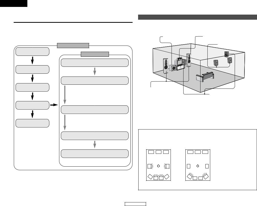
Easy to setup flow
Auto setup flow
Connecting a monitor
Playing a DVD with surround sound
1)Measuring the background noise (noise in the room)
2)Determining whether or not speakers are connected
3)Checking the polarities of the speakers
The measurement of the speakers
1)Speaker Configuration
2)Delay Time
3)Channel Level
4)Crossover Frequency
5)Room EQ
The measurement of the speakers
Check of the measurement result
Store the measurement result in the memory
Easy Setup and Operation
Speaker system layout
2 Basic system layout (For a THX Ultra2 system)
The following is an example of the basic layout for a system consisting of eight speaker systems and a television monitor:
Subwoofer |
Center speaker system |
Surround back speaker systems
Front speaker systems |
|
|
Set these at the sides of the TV or |
Surround speaker systems |
|
screen with their front surfaces as flush |
||
|
||
with the front of the screen as possible. |
|
Two surround back speakers are required to use the THX Ultra2 Cinema,THX Music mode and THX Games mode. Set the surround back speakers so that the distance to the listening position is the same for both the left and right speakers. It is also recommended that the deviations of the distance from the listening position to L and R channel speakers (front left (FL) and front right (FR), surround left (SL) and surround right (SR), surround back left (SBL) and surround back right (SBR)) is less than 60 cm (2 ft).
With the AVC-A11XV it is also possible to use the surround speaker selector function to choose the best layout for a variety of sources and surround modes.
2 Surround speaker selector function
This function makes it possible to achieve the optimum sound fields for different sources by switching between two systems of surround speakers (A and B). The settings of the different speakers (A only, B only or A+B) are stored in the memory for the different surround modes, so they are set automatically when the surround mode is selected.
A |
|
|
A |
B |
SB |
SB |
B |
|
|
Using A only
(Multi surround speaker system)
A |
|
|
A |
|
B |
SB |
SB |
B |
( SB : Surround back speakers) |
|
|
|||
|
Using B only |
|
||
(Single surround speaker system) |
|
|||
5
ENGLISH
Easy Setup and Operation
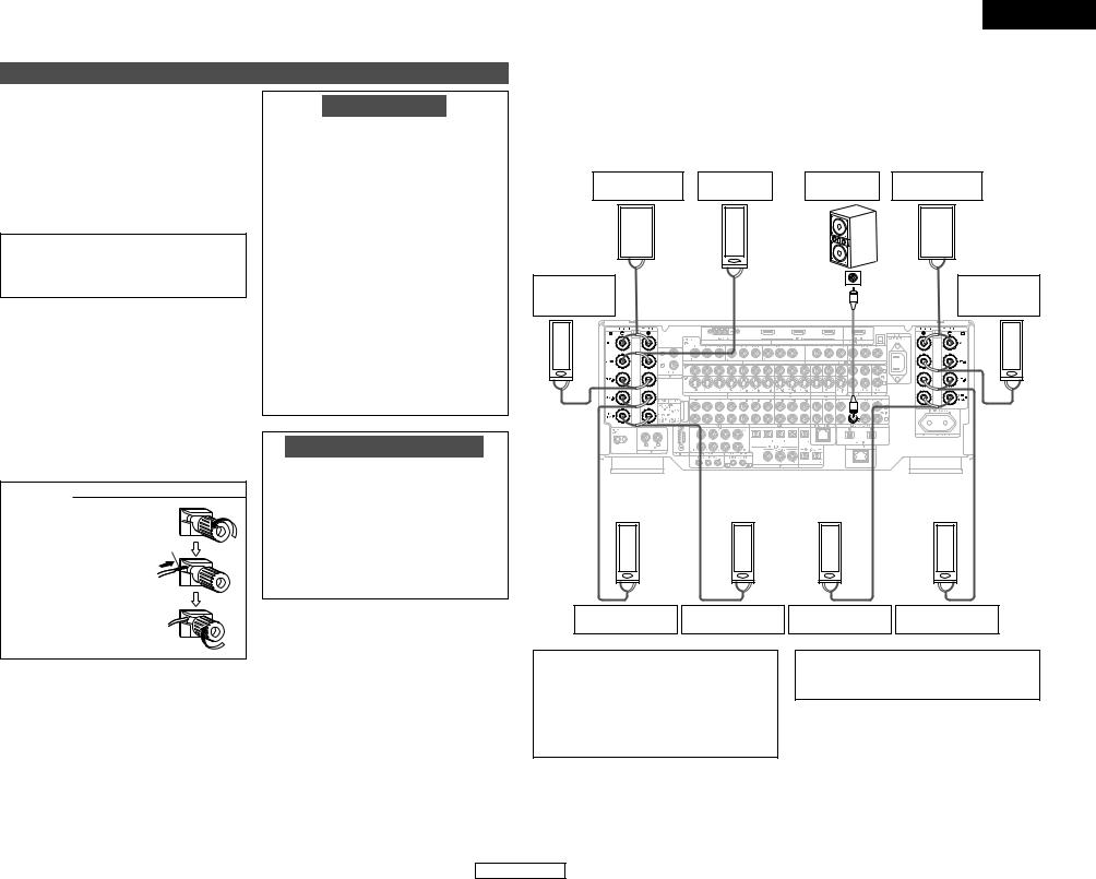
Speaker connections
•Connect the speaker terminals with the speakers making sure that like polarities are matched (< with <, > with >). Mismatching of polarities will result in weak central sound, unclear orientation of the various instruments, and the sense of direction of the stereo being impaired.
•When making connections, take care that none of the individual conductors of the speaker cable come in contact with adjacent terminals, with other speaker cable conductors, or with the rear panel.
NOTE:
NEVER touch the speaker terminals when the power is on. Doing so could result in electric shocks.
2 Speaker Impedance
•Speakers with an impedance of from 6 to 16 Ω /ohms can be connected for use as front, center, surround and surround back speakers.
•Be careful when using two pairs of surround
speakers (A + B) at the same time, since use of speakers with an impedance of less than 8 Ω /ohms
will lead to damage.
•The protector circuit may be activated if the set is played for long periods of time at high volumes when speakers with an impedance lower than the specified impedance are connected.
Connecting the speaker cables
1. Loosen by turning counterclockwise.
Either tightly twist or terminate the core wires.
2. Insert the cable.
3. Tighten by turning clockwise.
Protector circuit
This unit is equipped with a high-speed protection circuit. The purpose of this circuit is to protect the speakers under circumstances such as when the output of the power amplifier is inadvertently short-circuited and a large current flows, when the temperature surrounding the unit becomes unusually high, or when the unit is used at high output over a long period which results in an extreme temperature rise.
When the protection circuit is activated, the speaker output is cut off and the power supply indicator flashes. Should this occur, please follow these steps: be sure to switch off the power of this unit, check whether there are any faults with the wiring of the speaker cables or input cables, and wait for the unit to cool down if it is very hot. Improve the ventilation condition around the unit and switch the power back on.
If the protection circuit is activated again even though there are no problems with the wiring or the ventilation around the unit, switch off the power and contact a DENON service center.
Note on speaker impedance
The protector circuit may be activated if the set is played for long periods of time at high volumes when speakers with an impedance lower than the specified impedance (for example speakers with an impedance of lower than 4 Ω /ohms) are connected. If the protector circuit is activated, the speaker output is cut off. Turn off the set’s power, wait for the set to cool down, improve the ventilation around the set, then turn the power back on.
ENGLISH
Easy Setup and Operation
2 Connections
•The AVC-A11XV can be configured for 10 speaker playback using two pairs of surround speakers (A+B) and one pair of surround back speakers as shown below.
•The output of each power amplifier can be assigned to any desired channel to best suit the application.
For details, refer to “Setting the Channel Setup” and “Setting the Power Amplifier Assignment” (  page 49, 50).
•When making connections, also refer to the operating instructions of the other components.
Front |
Center |
Subwoofer |
Front |
|
|||
right speaker |
speaker |
left speaker |
|
||||
|
|
|
|||||
(R) |
|
|
|
|
|
(L) |
|
> < |
|
|
Connection terminal |
|
< |
> |
|
Surround |
> |
< |
IN |
|
Surround |
||
|
|
for subwoofer with |
|
||||
|
|
|
|
||||
right speaker |
|
|
built-in amplifier |
|
|
left speaker |
|
(A) |
|
|
(subwoofer), etc. |
|
|
(A) |
|
(R) |
|
|
|
|
|
|
(L) |
> < |
|
|
|
|
|
< |
> |
(R) |
(R) |
> < |
> < |
Surround |
Surround back |
right speaker (B) |
right speaker |
• Precautions when connecting speakers
If a speaker is placed near a TV or video monitor, the colors on the screen may be disturbed by the speaker’s magnetism. If this should happen, move the speaker away to a position where it does not have this effect.
|
(L) |
|
(L) |
< |
> |
< |
> |
Surround back |
Surround |
||
left speaker |
left speaker (B) |
||
NOTE:
•When using only one surround back speaker, connect it to left channel.
6
ENGLISH

ENGLISH
Easy Setup and Operation
Connecting a DVD player and monitor TV
•To connect the video output from the DVD player to the AVC-A11XV, you only need to choose one connection type. Component video connection offers the best quality (and is required for progressive DVD playback), followed by S-Video, while composite video offers the lowest picture quality of the three connection types. For more information about the video up conversion function (  page 12).
•The AVC-A11XV is equipped with HDMI connectors, so it can be connected to a DVD player or monitor TV using an HDMI cable. To connect it to a DVD player using a DVI-D cable (  page 17).
•To connect the digital audio output from the DVD player, you can choose from either the coaxial or optical connections. If you choose to use the optical connection, it needs to be assigned. For more information about Digital Input Assignment (  page 42).
•The AVC-A11XV is equipped with another set of input terminals for a non-DVD Video Disc Player (such as laser disc, VCD/SVCD, or future high definition disc player). The above connection guidelines for DVD also apply to the VDP input.
|
DVD player |
|
J |
COMPONENT VIDEO OUT |
|
|
|
Y |
|
|
PB |
|
|
PR |
L |
|
|
|
|
HDMI |
|
|
OUT |
H |
|
|
|
|
VIDEO |
|
|
OUT |
I |
|
|
|
|
S VIDEO |
|
|
OUT |
A |
|
AUDIO OUT |
L |
L |
L |
|
||
R |
R |
R |
D |
|
|
|
|
OPTICAL |
|
|
OUT |
C |
|
|
|
|
COAXIAL |
|
|
OUT |
Audio signal flow is shown with white arrows, white video signal flow is shown with gray arrows.
Easy Setup and Operation
•For best picture quality (especially with progressive DVD and other high definition sources) choose the component video connection to your monitor TV. S-Video and composite video outputs are also provided if your
TV does not have component video inputs.
J
L
H
I
Monitor TV
COMPONENT VIDEO IN
Y
 PB
PB
 PR
PR
HDMI
IN
VIDEO
IN
S VIDEO
IN
NOTE:
•The component video input and/or output jacks may be labeled differently on some TVs, monitors or video components (Y, PB, PR; Y, CB, CR; Y, B-Y, R-Y). Check the owner’s manuals for other components for further information.
•The COMPONENT MONITOR OUT-1 and the COMPONENT MONITOR OUT-2 can be used simultaneously.
•Audio signals are only output from the HDMI monitor out terminal when audio signals are input to the HDMI input terminal.
•When connecting the AVC-A11XV and DVD player using an HDMI cable, also connect the AVC-A11XV and monitor TV using an HDMI cable (  page 16).
7
ENGLISH
Easy Setup and Operation
Auto Setup / Room EQ
The Auto Setup and Room EQ function of this unit performs an analysis of the speaker system and measures the acoustic characteristics of your room to permit an appropriate automatic setting.
The AVC-A11XV’s Audyssey MultEQ XT function has the feature that it provides the optimum listening environment at all listening positions in the home theater, where there are often multiple listeners viewing programs together. To achieve this, it is first necessary to use a microphone to measure test tones generated from the different speakers at the various listening positions. All this measured data is analyzed with a unique method to comprehensively improve acoustic characteristics in the listening area. For optimum effectiveness, measurements should be performed at six or more points. Move the microphone successively within the listening area surrounded by the speakers as shown on the diagram below to measure the test tones. When listening to music or viewing movies with the whole family, move the microphone successively to the different positions in which the members of the family sit (“ ” on the diagram indicates the points of installation) and measure repeatedly (Example q). Even if the number of people using the home theater is small, taking multiple measurements at or near the listening
makes it possible to correct the sound more (Example w).
-A11XV’s Room EQ function offers three curves: “Audyssey”, “Front” and “Flat”. can be selected after performing the auto setup
. Details of the different correction curves below.
:
adjusts the frequency response of all speakers the effects of room acoustics.
:
adjusts the characteristics of each speaker to of the front speakers.
the frequency response of all speakers flat. suitable for multi-channel music reproduction,
discrete music sources such as Dolby Digital DVD-Audio and Super Audio CD.
MEMO
•To make the Speaker system settings without using the Auto Setup function (  page 53 ~ 57).
•When performing Auto Setup, an optional microphone is required for setup.
2 About the main listening position
(*M)
The main listening position is the point where a listener sits most often or the listening position when only one person is listening. Measurements on the AVC-A11XV start from this point. Correction for the speaker distance (“Delay Time”) is set based on this point.
Example: q
*M
Example: w
*M
POWER |
ENTER |
SETUP MIC |
ON/STANDBY SETUP CURSOR
Connecting a microphone
1 Connect the optional microphone for Auto Setup to the SETUP MIC jack on the front panel of the unit.
2 Mount the auto setup microphone onto a camera tripod, etc., and place it at ear height at the main listening position in the listening room with the sound receptor facing the ceiling.
Microphone
ENGLISH
Easy Setup and Operation
ON
AMP
ENTER
 CURSOR
SETUP 


When placing the microphone, adjust the height so that the microphone’s sound receptor is at the height of the ears of the listener.
Be sure that at the beginning, the measurement is started with the microphone set up at the main listening position.
It is not possible to measure properly if there are any obstacles between the speakers and microphone. Check that there are no obstacles.
Please do not stand between or near the speakers and the microphone during the measurements.
NOTE:
•Do not disconnect the microphone until the settings are completed.
•Do not change the connection of speakers or the subwoofer’s volume after performing these measurements.
8
ENGLISH
ENGLISH
Easy Setup and Operation
Turning on the power
1 Turn on your subwoofer.
Set the volume to halfway and set the crossover frequency to the maximum or Low pass filter off if your subwoofer can adjust the output volume and the crossover frequency.
Some subwoofers have a standby mode. Be sure to turn this function off before performing the Auto Setup procedure.
2 Turn on your monitor (TV).
3 Press the POWER switch.
¢ ON:
The power turns on and the power indicator lights. Set the POWER switch to this position to turn the power on and off from the included remote control unit.
£ OFF:
The power turns off and indicator is off.
In this position, the power cannot be turned on and off from the remote control unit.
4 Press the ON/STANDBY switch on the main unit or ON button on the remote control unit.
•When pressed, the power turns on and the display lights.
•When pressed again, the power turns off, the standby mode is set and the display turns off.
The sound is muted for several seconds, after which the unit operates normally.
Whenever the ON/STANDBY button is in the standby state, the apparatus is still connected to the AC line voltage. Please be sure to turn off the POWER switch or unplug the cord when you leave home for, say, a vacation.
5 Press the AMP button to select the “AMP” (only when operating with the remote control unit).
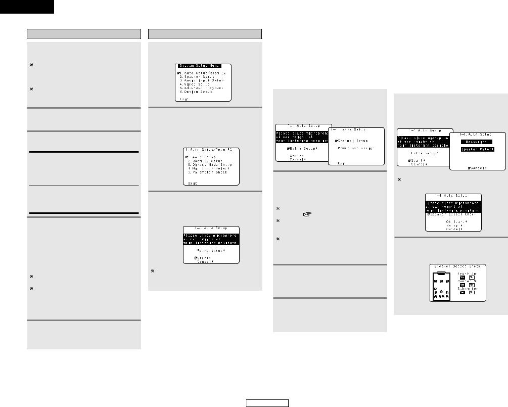
Starting Auto Setup
1 |
Press the SETUP button. |
|
|
|
• Display the “System Setup Menu”. |
2 Press the CURSOR D or H button to select the “Auto Setup / Room EQ”, then press the ENTER button.
•Display the “Auto Setup / Room EQ” menu screen.
3 Press the CURSOR D or H button to select the “Auto Setup”, then press the ENTER button.
• Display the “Auto Setup” screen.
The message “Connect Microphone” is displayed if no microphone is connected. If so, connect the auto setup microphone.
Easy Setup and Operation
Extra Setup |
|
Preliminary Measurements |
|
|
|
The AVC-A11XV has seven available amplifier channels, some of which can be assigned for powering speakers in ZONE2 and ZONE3, depending on the speaker system complement in the main room. If this functionality is not needed, skip this “Extra Setup” procedure and proceed to “Preliminary Measurements” (  page 9, 10).
1 Press the CURSOR D or H button to select the “Extra Setup”, then press the CURSOR F button.
• Switch to the “Extra Setup” screen.
2 Press the CURSOR D or H button to choose the setting you want to change, then press the ENTER button.
• Switch to the setting screen.
For instructions on making the “Channel Setup”
settings ( |
page 49). |
For instructions on making the “Setting the Power Amplifier Assignment” settings (  page 49, 50).
The speakers measured with this Auto Setup procedure are based on the setting of these “Channel Setup” and “Power Amp Assign” functions.
3 Once the settings are completed, press the ENTER button at the each setting screen.
• The “Extra Setup” menu reappears.
4 Press the CURSOR D or H button to select the “Exit”, then press the ENTER button.
• Return to the “Auto Setup” screen.
•This procedure is used to automatically determine the background noise, whether or not speakers are connected, and the polarities of the connected speakers.
•To avoid affecting the measurements, turn off the air-conditioner or any other device that makes noise and take the measurements with the room as quiet as possible.
1 Press the CURSOR D or H button to select the “Start”, then press the CURSOR F button.
• Start the preliminary measurements.
The screen shown at the below appears once the preliminary measurements are completed.
2 |
Press the ENTER button. |
• Switch to the “Speaker Detect Check” |
screen.
[ First screen ]
9
ENGLISH
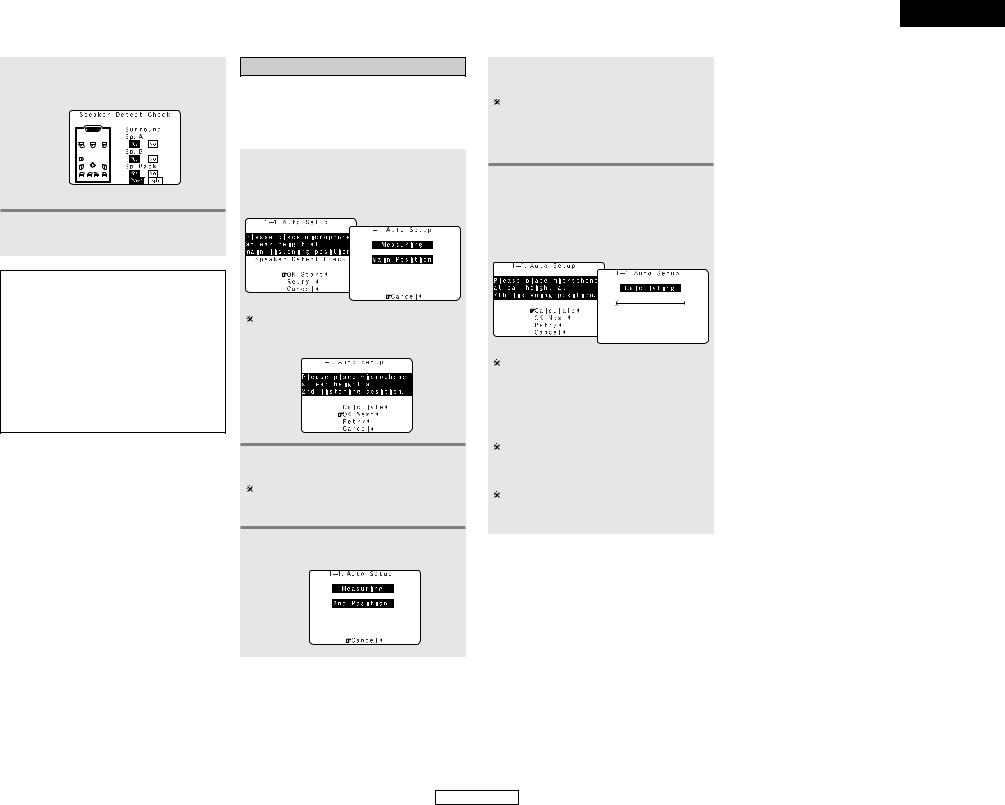
Easy Setup and Operation
3 Check the results of the speaker detection, then press the ENTER button.
• Switch to the second screen.
[ Second screen ]
4 If the check ends, press the ENTER button again.
NOTE:
•If the results are not as expected or if an error message is displayed, select “Retry” and perform the measurements again. (For details on the error messages (  page 11).)
If the results of remeasurement are still not as expected or if an error message is displayed, turn off the power switch and check the speaker connections. Then start the measurements again from the beginning.
•Measurement is cancelled when MASTER VOLUME is operated while the Auto Setup is performed.
Speaker system measurement
With these measurements, the “Speaker Configuration”, “Delay Time”, “Channel Level”, “Crossover Frequency” and “Room EQ” are analyzed automatically. The main listening position is measured first, so leave the microphone where it is.
1 Press the CURSOR D or H button to select the “OK Start”, then press the CURSOR F button.
• Measurements for the first point start.
4 Perform step 2, 3 repeatedly.
The more measurement points, the better the resulting room correction effect. We recommend a minimum of 6 measurement points – 8 measurement points provides the best room correction effect.
5 After measuring at the number of points according to your listening environment, press the CURSOR D or H button to select the “Calculate”, then press the CURSOR F button.
The screen shown at the below appears once the measurements for the main listening position are completed.
2 Next the measurements for the second point will be taken.
Place the microphone at the second listening position. For instructions on the position in which the microphone should be placed (  page 8).
3 |
Press the CURSOR F button. |
|
|
|
• Measurements for the second point start. |
10
• The speaker system is analyzed.
The amount of time required for the analysis depends on the number of speakers and the number of measuring points. The greater the number of speakers and measuring points, the longer the time required. For example, for ten speaker systems and 6 measuring points, the calculations require approximately 6 minutes.
Measurements can be ended when there are 5 or less measurement locations; however, to obtain better results, measurements at 6 or more locations is recommended.
Once the calculations are completed, a screen for confirming the results of the measurements appears.
ENGLISH
Easy Setup and Operation
ENGLISH
ENGLISH
Easy Setup and Operation
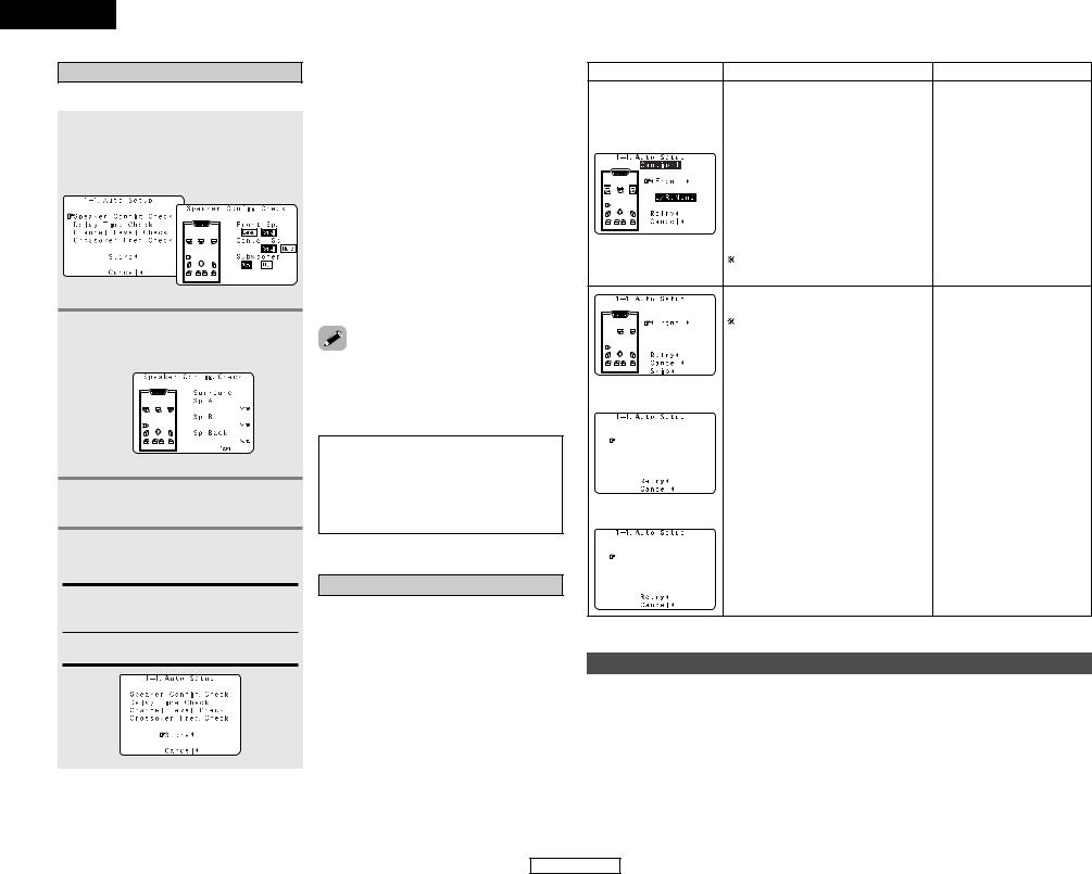
Check of the measurement result
The results of the measured items can be checked.
1 Press the CURSOR D or H button to select the items, then press the ENTER button.
• Switch to the verification screen.
Example: Speaker Config. Check
[ First screen ]
2 |
Press the ENTER button. |
|||||
|
||||||
|
• Switch to the second screen. |
|||||
|
Example: Speaker Config. Check |
|||||
|
|
|
|
|
|
|
|
|
|
|
|
|
|
|
|
|
|
|
|
|
|
|
|
|
|
|
|
|
|
|
|
|
|
|
|
|
|
|
|
|
|
|
|
|
|
|
|
|
[ Second screen ]
3 If the check ends, press the ENTER button again.
4 Press the CURSOR D or H button to select whether or not to save the data you have checked.
Store:
Set with the checked measurement value.
All parameters are stored up.
Cancel:
Cancel the auto setup settings.
5 |
Press the CURSOR F button. |
|
|
|
• After the data is stored, the “Auto Setup / |
|
Room EQ” menu screen appears |
|
automatically. |
|
|
• Sometimes due to the electrical complexities of subwoofers and the interaction with the room, THX recommends setting the level and the distance of
subwoofer manually.
due to interaction with the room, you notice irregular results when setting the level distance of the main speakers. If this THX recommends setting them manually. note that any THX main speakers should be Small (80 Hz). If you set up your speakers Auto Setup, please make sure manually that THX speakers are set to Small with 80 Hz
.
•When measurements have been made using the measurement microphone, speakers with a built-in filter such as subwoofers might be set with a value that differs from the physical distance because of the internal electrical delay.
NOTE:
•Do not turn off the power while the data is being stored. If the power is turned off while the data is being stored, the Room EQ parameters stored in the memory will be cleared, and it will not be possible to select the “Audyssey”, “Front” or “Flat” equalizer settings.
About the error message
These error messages will be displayed when performing the measurements of Auto Setup and the automatic measurements can not be completed because of the speaker arrangement, measurement environment, or other factors. Please check the following matters, reset the pertinent items, and measure again. Be sure to turn off the AVC-A11XV’s power before checking the speaker connections.
Easy Setup and Operation
Screen example |
Cause |
Measures |
|
|
|
q The speakers required for producing • Check that the pertinent speakers suitable reproduction have not been are properly connected. detected.
•The front L and front R speakers were not properly detected.
• Only one channel of the surround (A) and surround (B) speakers was detected.
• Sound was output from the R channel when only one surround back speaker was connected.
• The surround back or the surround (B) speaker was detected, but the surround
(A) speaker was not detected.
If multiple errors occur, press the CURSOR F or G button to check the contents.
|
|
|
|
|
|
|
|
|
|
w The speaker polarity is connected |
in • Check |
the |
polarity of |
the |
||
|
|
|
|
|
|
|
|
|
|
reverse. |
|
pertinent speakers. |
|
|||
|
|
|
|
|
|
|
|
|
|
|
|
|||||
|
|
|
|
|
|
|
|
|
|
If multiple errors occur, press the CURSOR • For some speakers, the screen |
||||||
|
|
|
|
|
|
|
|
|
|
F or G button to check the contents. |
|
below may be displayed even |
||||
|
|
|
|
|
|
|
|
|
|
|
||||||
|
|
|
|
|
|
|
|
|
|
|
|
though the speakers are properly |
||||
|
|
|
|
|
|
|
|
|
|
|
|
connected. |
|
|
|
|
|
|
|
|
|
|
|
|
|
|
|
|
|
|
|
||
|
|
|
|
|
|
|
|
|
|
|
|
If so, select “Skip0”. |
|
|||
|
|
|
|
|
|
|
|
|
|
|
||||||
|
|
|
|
|
|
|
|
|
|
e There is too much ambient noise in the • Either turn off the power of the |
||||||
|
|
|
|
|
|
|
|
|
|
room and the measurements cannot be |
device that generated the noise |
|||||
|
|
|
|
|
|
|
|
|
|
made accurately. |
|
during the |
measurements |
or |
||
|
|
|
|
|
|
|
|
|
|
|
||||||
|
|
|
|
|
|
|
|
|
|
|
|
move the device away. |
|
|||
|
|
|
|
|
|
|
|
|
|
|
|
• Try again at a time when it is |
||||
|
|
|
|
|
|
|
|
|
|
|
|
quieter. |
|
|
|
|
|
|
|
|
|
|
|
|
|
|
|
|
|
|
|
|
|
|
|
|
|
|
|
|
|
|
|
r The sound level that is output from the • Check |
the |
|
placement |
and |
||
|
|
|
|
|
|
|
|
|
|
speakers and/or subwoofer is too low. |
|
orientation of the loudspeakers. |
||||
|
|
|
|
|
|
|
|
|
|
|
||||||
|
|
|
|
|
|
|
|
|
|
|
|
• Adjust the subwoofer’s output |
||||
|
|
|
|
|
|
|
|
|
|
|
|
level. |
|
|
|
|
|
|
|
|
|
|
|
|
|
|
|
|
|
|
|||
|
|
|
|
|
|
|
|
|
|
t The measurement microphone is |
not • Connect |
the |
measurement |
|||
|
|
|
|
|
|
|
|
|
|
connected, or all of speakers have |
not |
microphone |
to |
the microphone |
||
|
|
|
|
|
|
|
|
|
|
|||||||
|
|
|
|
|
|
|
|
|
|
been detected. |
|
connector. |
|
|
|
|
|
|
|
|
|
|
|
|
|
|
|
|
|
|
|||
|
|
|
|
|
|
|
|
|
|
|
|
• Check the speaker connection. |
||||
Playing a DVD with surround sound
Disconnect the microphone from the |
|
4 Start DVD playback. |
|
1 unit. |
|
||
2 Select the input source to be played. |
|
5 Adjust the volume. |
|
3 Select the play mode. |
|
|
|
11
ENGLISH
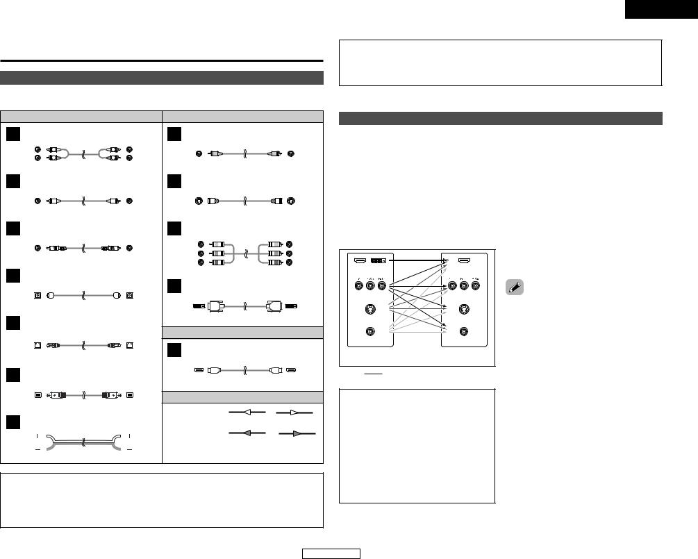
Connecting Other Sources
Cable indications
The hookup diagrams on the subsequent pages assume the use of the following optional connection cables (not supplied).
|
|
Audio cable |
|
|
Video cable |
|
|
|
A |
Analog terminal (Stereo) |
|
H |
Video terminal |
|
|
|
|
(White) |
L |
L |
(Yellow) |
|
|
|
||
(Red) |
R |
R |
|
|
|
|||
|
|
|
|
|
||||
|
|
Pin-plug cable |
|
|
Video cable (75 Ω /ohms video pin-plug cable) |
|||
B |
Analog terminal (Monaural, for subwoofer) |
I |
S video terminal |
|
|
|
||
|
|
Pin-plug cable |
|
|
S video cable |
|
|
|
C |
Digital terminal (Coaxial) |
|
J |
Component video terminal |
|
|
||
(Orange) |
|
|
(Green) |
|
|
(Y) |
||
|
|
(Blue) |
|
|
(PB/CB) |
|||
|
|
|
|
|
|
|||
|
Coaxial cable (75 Ω /ohms pin-plug cable) |
|
(Red) |
|
|
(PR/CR) |
||
D |
Digital terminal (Optical) |
|
|
Component video cable |
|
|||
|
K |
|
|
|
|
|||
|
|
|
|
DVI-D terminal |
|
|
|
|
|
|
Optical cable (Optical fiber cable) |
|
|
|
|
|
|
E |
DENON LINK terminal |
|
|
24-pin DVI-D cable |
|
|
||
|
|
Audio and Video cable |
|
|||||
|
|
|
|
|
|
|||
|
|
|
|
L |
HDMI terminal |
|
|
|
|
|
DENON LINK cable |
|
|
|
|
|
|
F |
IEEE1394 terminal |
|
|
HDMI cable |
|
|
||
|
|
|
|
|
|
|
||
|
|
|
|
|
Signal direction |
|
|
|
|
|
4-pin, S400 IEEE1394 cable |
|
Audio signal |
|
|
|
|
G |
|
|
|
|
OUT |
OUT |
IN |
|
Speaker terminal |
|
|
IN |
|||||
|
|
|
|
|
|
|||
|
|
|
|
|
Video signal |
OUT |
OUT |
IN |
|
|
|
|
|
IN |
|||
|
|
Speaker cable |
|
|
|
|
|
|
NOTE:
•Do not plug in the Power supply cord until all connections have been completed.
•When making connections, also refer to the operating instructions of the other components.
•Be sure to connect the left and right channels properly (left with left, right with right).
•Note that binding pin-plug cables together with Power supply cords or placing them near a power transformer will result in generating hum or other noise.
ENGLISH
Connecting Other Sources
NOTE:
•Connecting a LD (laser disc) player with a Dolby Digital RF Output.
The AVC-A11XV does not have a DD RF demodulator function. Therefore, you need to use a commercially available outboard DD RF demodulator and connect its digital output to one of the AVC-A11XV available digital inputs. Refer to the demodulator’s owner’s manual for further information.
The video conversion function
The AVC-A11XV is equipped with a function for up and down converting video signals.
Because of this, the AVC-A11XV’s MONITOR OUT terminal can be connected to the monitor (TV) with a set of cables offering a higher quality connection, regardless of how the player and the AVC-A11XV’s video input terminals are connected.
Generally speaking, analog video connections using the component video terminals offer the highest quality playback, followed by connections using the S- Video terminals, then connections using the regular video terminals (yellow).
The flow of the video signals.
(HDMI / DVI-D |
(HDMI |
terminals) |
terminal) |
(Component |
(Component |
Video terminals) |
Video terminals) |
(S-Video terminal) |
(S-Video terminal) |
(Video terminal) |
(Video terminal) |
This unit’s |
This unit’s output |
input terminals |
terminals |
: only MAIN ZONE 480i/576i
NOTE:
•It is not possible to down-convert from HDMI and DVI-D input signals to the component, S-Video or composite video monitor output terminals.
•Video down conversion to the MAIN ZONE’s monitor output is only possible when the component video input resolution is 480i (interlaced standard definition video – NTSC format, for North America) or 576i (interlaced standard definition video – PAL format, for Europe and other countries).
•To change the setting of the video conversion mode for the MAIN ZONE (  page 45).
analog video to HDMI function:
-A11XV’s video up-conversion function lets analog video input signals (component – 480p/576p, 1080i or 720p; S-Video and video - 480i/576i) to the HDMI monitor
terminal with the original resolution.
screen display signals are output from the monitor output terminal with a resolution of
. Because of this, if the monitor equipped HDMI terminal is compatible with the 480i/576i all the signals the AVC-A11XV handles output to the monitor with a single HDMI
. The resolutions with which the monitor is can be checked using the STATUS button main unit or the ON SCREEN button on the
control unit.
•If the monitor equipped with HDMI terminal is not compatible with the 480i/576i resolution, connect the player and the AVC-A11XV using a component cable and set the player’s resolution to one which the monitor can handle.
•If you do not want to use the function for converting analog video signals to HDMI signals, select “OFF” for “Analog to HDMI Convert” at “Setting the HDMI Out Setup”(  page 46).
In this case, the function for video up conversion to the component video terminal operates.
12
ENGLISH
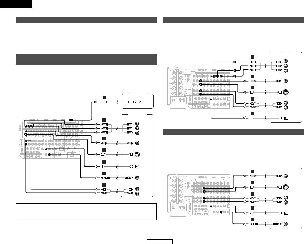
ENGLISH
Connecting Other Sources
On screen display for component video outputs and HDMI output
•When viewing component video signals or HDMI signals via the AVC-A11XV, the on screen display is displayed on the monitor when the “System Setup” operations are performed and when the remote control unit’s ON SCREEN button is operated.
•To view the on screen display using an HDMI monitor, set “Analog to HDMI Convert” at “HDMI Out Setup” to “ON” (default).
•When only component video signals are input to the AVC-A11XV or when “Component” is selected at the “Setting the Video Convert Mode”, the characters of the on screen display are not displayed over the picture.
Connecting equipment with HDMI (High-Definition Multimedia Interface) terminals [To convert analog video signals to HDMI signals]
•The AVC-A11XV is equipped with a function for converting analog video signals into HDMI signals. You can do this by either a component or a video or a S-video connection.
•Audio signals are not output from the HDMI monitor output terminal, so also make analog or digital audio connections. To play sound using digital audio connections, assign the digital terminal (coaxial or optical) at “Setting the Digital In Assign” (  page 42).
Monitor TV
L
HDMI
IN
|
DVD player |
|
J |
COMPONENT VIDEO OUT |
|
|
|
Y |
|
|
PB |
|
|
PR |
H |
|
|
|
|
VIDEO |
|
|
OUT |
I |
|
|
|
|
S VIDEO |
|
|
OUT |
D |
|
|
|
|
OPTICAL |
|
|
OUT |
C |
|
|
|
|
COAXIAL |
|
|
OUT |
A |
|
AUDIO OUT |
L |
L |
L |
R |
R |
R |
NOTE:
•Use an HDMI monitor compatible with an HDMI input resolution of 480i or 576i.
•If your monitor is not equipped with an HDMI terminal, connect the AVC-A11XV to the monitor using the component video, S-Video, or composite video terminals.
Connecting Other Sources
Connecting a TV tuner
•For best picture quality choose the component video connection to your TV. S-video and composite video outputs are also provided if your TV does not have component video inputs.
•To connect the digital audio output from the TV, you can choose from either the coaxial or optical connections. If you choose to use the coaxial connection, it needs to be assigned. For more information about Digital Input Assignment (  page 42).
|
|
TV |
J |
COMPONENT VIDEO OUT |
|
|
|
Y |
|
|
PB |
|
|
PR |
H |
|
|
|
|
VIDEO |
|
|
OUT |
I |
|
|
|
|
S VIDEO |
|
|
OUT |
A |
|
AUDIO OUT |
L |
L |
L |
R |
R |
R |
D |
|
|
|
|
OPTICAL |
|
|
OUT |
Connecting a DBS tuner
•For best picture quality choose the component video connection to your DBS tuner. S-video and composite video outputs are also provided. If you choose to use the component video connection, it needs to be assigned. For more information about Component Input Assignment (  page 45).
•To connect the digital audio output from the DBS tuner, you can choose from either the coaxial or optical connections. If you choose to use the coaxial or the optical connection, if needs to be assigned. For more information about Digital Input Assignment (  page 42).
DBS / BS Tuner
H
VIDEO
OUT
I
S VIDEO
OUT
A |
|
AUDIO OUT |
L |
L |
L |
R |
R |
R |
D
OPTICAL
OUT
C
COAXIAL
OUT
13
ENGLISH
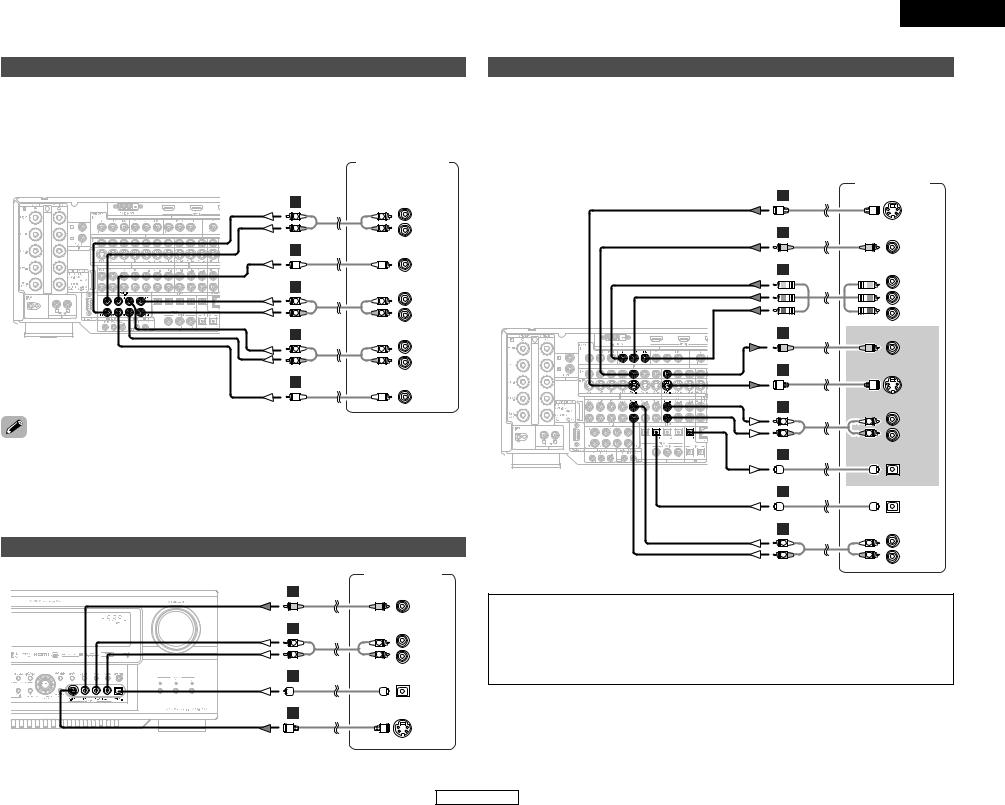
Connecting Other Sources
Connecting the external inputs (EXT. IN) terminals
•These terminals are for inputting multi-channel audio signals from an outboard decoder, or a component with a different type of multi-channel decoder, such as a DVD Audio player, or a multi-channel Super Audio CD player, or other future multi-channel sound format decoder.
•The method of video signal connection is the same as that for DVD player (  page 7).
•For instructions on playback using the external input (EXT. IN) terminals (  page 21).
|
DVD Audio-Video / |
||
|
Super Audio CD Player / |
||
|
External decoder |
||
A |
7.1ch AUDIO OUT |
||
L |
L |
FRONT |
|
L |
|||
R |
R |
R |
|
B |
|
|
|
|
|
CENTER |
|
A |
|
SURROUND |
|
L |
L |
BACK |
|
L |
|||
R |
R |
R |
|
A |
|
SURROUND |
|
L |
L |
||
L |
|||
R |
R |
R |
|
B |
|
|
|
|
|
SUB- |
|
|
|
WOOFER |
|
using the DENON LINK connector Digital transfer and multi-channel playback of DVD audio discs and multi-channel sources is possible by connecting the AVC-A11XV to a DENON DVD player equipped with
LINK connector using the connection cable included with the DVD player.
discs on which special copyright protection measures have been taken, however, the digital signals may output from the DVD player. In this case, connect the DVD player’s analog multi-channel output to the
A11XV’s EXT. IN terminals for playback. Also refer to your DVD player’s operating instructions.
a video camera component or video game component
Video camera /
Video game
H
VIDEO
OUT
A |
|
AUDIO OUT |
L |
L |
L |
R |
R |
R |
D
OPTICAL
OUT
I
S VIDEO
OUT
ENGLISH
Connecting Other Sources
Connecting a DVD recorder
•For best picture quality choose the component video connection to your DVD recorder. S-video and composite video outputs are also provided. If you choose to use the component video connection, it needs to be assign. For more information about Component Input Assignment (  page 45).
•If you wish to perform analog dubbing from a digital sources, such as a DVD recorder to an analog recorder such as a cassette deck, you will needs connect analog inputs and outputs as shown below, in addition to the digital audio connections.
DVD recorder
I
|
|
S VIDEO |
|
|
OUT |
H |
|
|
|
|
VIDEO |
|
|
OUT |
J |
COMPONENT VIDEO OUT |
|
|
|
Y |
|
|
PB |
|
|
PR |
H |
|
|
|
|
VIDEO |
|
|
IN |
I |
|
|
|
|
S VIDEO |
|
|
IN |
A |
|
AUDIO IN |
L |
L |
L |
|
||
R |
R |
R |
D |
|
|
|
|
OPTICAL |
|
|
IN |
D |
|
|
|
|
OPTICAL |
|
|
OUT |
A |
|
AUDIO OUT |
L |
L |
L |
|
||
R |
R |
R |
NOTE:
•When recording to DVD recorder, it is necessary that the type of cable used with the playback source equipment be the same type that is connected to the AVC-A11XV VCR-1 (to 3) OUTPUT terminal.
(Example) VCR-1 IN → |
S-video cable : VCR-1 OUT → |
S-video cable |
VCR-1 IN → |
video cable : VCR-1 OUT → |
video cable |
•Do not connect the output of the component connected to the OPTICAL 2 OUT terminal on the AVCA11XV’s rear panel to any terminal other than the OPTICAL 2 IN terminal.
14
ENGLISH
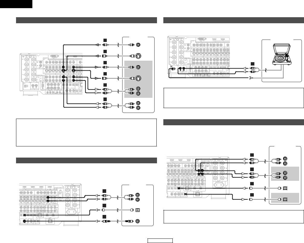
ENGLISH
Connecting Other Sources
Connecting a VCR
•There are three sets of video deck (VCR) terminals, so three video decks can be connected for simultaneous recording or video copying.
Video deck
H
VIDEO
OUT
I
S VIDEO
OUT
H
VIDEO
IN
I
|
|
S VIDEO |
|
|
IN |
A |
|
AUDIO IN |
L |
L |
L |
R |
R |
R |
A |
|
AUDIO OUT |
L |
L |
L |
|
||
R |
R |
R |
Connecting Other Sources
Connecting a turntable
• You can connect the turntable (MM cartridge) to the PHONO terminals.
Turntable
Turntable (MM cartridge)
A |
|
L |
AUDIO OUT |
R |
|
|
GND |
NOTE:
•The phono input can accept signals from moving magnet (MM) and high output moving coil (MC) phono cartridges. If your turntable is equipped with a low output MC cartridge, you will need to use a separate MC head amplifier or step-up MC transformer.
•If humming or other noise is generated when the ground wire is connected, disconnect the ground wire.
NOTE:
•When recording to VCR, it is necessary that the type of cable used with the playback source equipment be the same type that is connected to the AVC-A11XV VCR-1 (to 3) OUTPUT terminal.
(Example) VCR-2 IN → |
S-video cable : VCR-2 OUT → |
S-video cable |
VCR-2 IN → |
video cable : VCR-2 OUT → |
video cable |
•Do not connect the output of the component connected to the OPTICAL 3 OUT terminal on the AVCA11XV’s rear panel to any terminal other than the OPTICAL 3 IN terminal.
Connecting a CD player
•To connect the digital audio output from the CD player, you can choose from either the coaxial or optical connections. If you choose to use the optical connection, it needs to be assigned. For more information about Digital Input Assignment (  page 42).
|
|
CD player |
A |
|
AUDIO OUT |
|
|
|
L |
L |
L |
|
||
R |
R |
R |
D
OPTICAL
OUT
C
COAXIAL
OUT
Connecting a CD recorder or MD recorder
•If you wish to perform analog dubbing from a digital source, such as a CD or MD recorder to an analog recorder such as a cassette deck, you will need to connect analog inputs and outputs as shown below, in addition to the digital audio connections.
|
CD recorder / |
|
|
MD recorder |
|
A |
|
AUDIO OUT |
|
|
|
L |
L |
L |
R |
R |
R |
A |
|
AUDIO IN |
|
|
|
L |
L |
L |
|
||
R |
R |
R |
D |
|
|
|
|
OPTICAL |
|
|
OUT |
D |
|
|
|
|
OPTICAL |
|
|
IN |
NOTE:
•Do not connect the output of the component connected to the OPTICAL 4 OUT terminal on the AVCA11XV’s rear panel to any terminal other than the OPTICAL 4 IN terminal.
15
ENGLISH
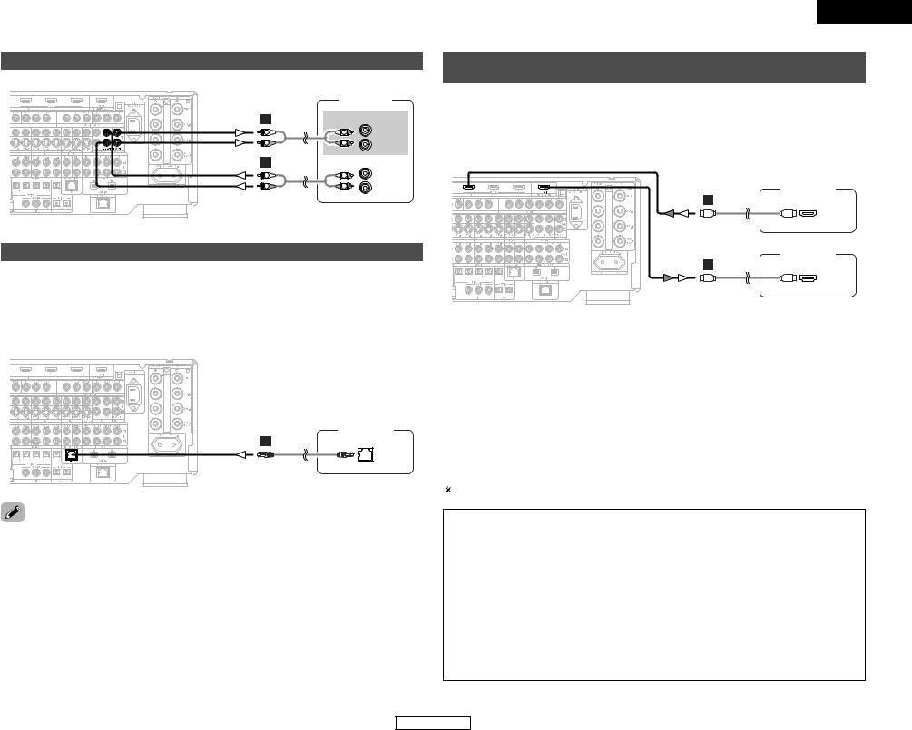
Connecting Other Sources
Connecting a tape deck
|
Tape deck |
|
A |
|
AUDIO IN |
|
|
|
L |
L |
L |
R |
R |
R |
A |
|
AUDIO OUT |
|
|
|
L |
L |
L |
|
||
R |
R |
R |
DENON LINK connections
•High quality digital sound with reduced digital signal transfer loss can be enjoyed by connecting a separately sold DENON LINK compatible DVD player.
•Digital transfer and multi-channel playback of DVD Audio discs and other multi-channel sources is possible by connecting the AVC-A11XV to a DENON DVD player equipped with a DENON LINK connector using the connection cable included with the DVD player.
•When a DENON DVD player and the DENON LINK have been connected, be sure to make a setting to “DENON LINK” with the System Setup Digital In Assignment (  page 42).
DVD player
E
DENON
LINK
ENGLISH
Connecting Other Sources
Connecting equipment with HDMI (High-Definition Multimedia Interface) terminals
•A simple 1-cable connection (using a commercially available cable) with a device having an HDMI (HighDefinition Multimedia Interface) connector allows digital transfer of the digital images of DVD video and other sources, and the multi-channel sound of DVD Audio and DVD Video.
•To provide audio output from AVC-A11XV’s audio output connector, select “Amp” at the System Setup.
To provide audio output from the TV, select “TV” at the System Setup. For details, see “Setting the HDMI/DVI In Assign” (  page 44, 45).
DVD player
L
HDMI
OUT
Monitor TV
L
HDMI
IN
Input signals |
|
||
|
|
|
|
|
LINEAR PCM |
C |
|
DVD Video |
Dolby Digital |
C |
|
|
DTS |
C |
|
|
LINEAR PCM |
|
|
DVD Audio |
PACKED PCM |
C |
|
(with CPPM / |
|||
|
|
||
|
without CPPM) |
|
|
|
|
|
|
CD |
LINEAR PCM |
C |
|
|
Multi area |
E |
|
Super Audio CD |
Stereo area |
E |
|
|
CD area |
C |
|
The AVC-A11XV is HDMI Ver. 1.1 compatible.
2 Copyright Protection System
To play back the digital video and audio of DVD video and DVD audio through an HDMI/DVI-D connection, both the connected player and monitor are required to support a copyright protection system called HDCP (High-bandwidth Digital Content Protection System). HDCP is copy protection technology that comprises data encryption and authentication of the partner equipment.
The AVC-A11XV supports HDCP. Please see the user’s manual of your video display for more information about this.
discs on which special copyright protection measures have been taken, however, the digital signals may output from the DVD player. In this case, connect the DVD player’s analog multi-channel output to the
A11XV’s EXT. IN terminals for playback.
refer to your DVD player’s operating instructions.
2 DENON LINK 3rd Edition
Super Audio CDs have certain rules for digital signal transfer designed to protect copyrights. In order to receive permission for the transfer of the multi-channel digital signals of Super Audio CDs, DENON has proposed to Super Audio CD licensors and content holders the DENON LINK (3rd Edition), and approval procedures are now underway. Once these approval procedures are completed and official approval for the digital transfer of Super Audio CD signals with DENON LINK is received, it will be possible to transfer the digital signals of Super Audio CDs to the AVC-A11XV from players equipped with DENON LINK (3rd Edition).
NOTE:
•The audio signals on the multi/stereo area of Super Audio CDs are not output. If the Super Audio CD is a hybrid CD, only the audio signals in the CD area are output.
•Use a compatible player to play DVD Audio discs that are copyright protected by CPPM.
•Among the devices that support HDMI, some devices can control other devices via the HDMI connector; however, the AVC-A11XV cannot be controlled by another device via the HDMI connector.
•The audio signals from the HDMI connector (including the sampling frequency and bit length) may be limited by the equipment that is connected.
•The video signals are not output properly if a device not compatible with HDCP is used.
•Use an HDMI monitor compatible with an HDMI input resolution of 480i or 576i.
•The video signals input from the HDMI or DVI-D input terminals are output to the HDMI monitor with their original resolution, so the image will not be displayed if the resolutions of the input signal and the monitor being used are not matched. In this case, change the setting of the resolution on the source device (player) to one which the monitor can handle.
•For stable signal transfer, we recommend using cables that are a maximum of 5 meters in length.
16
ENGLISH
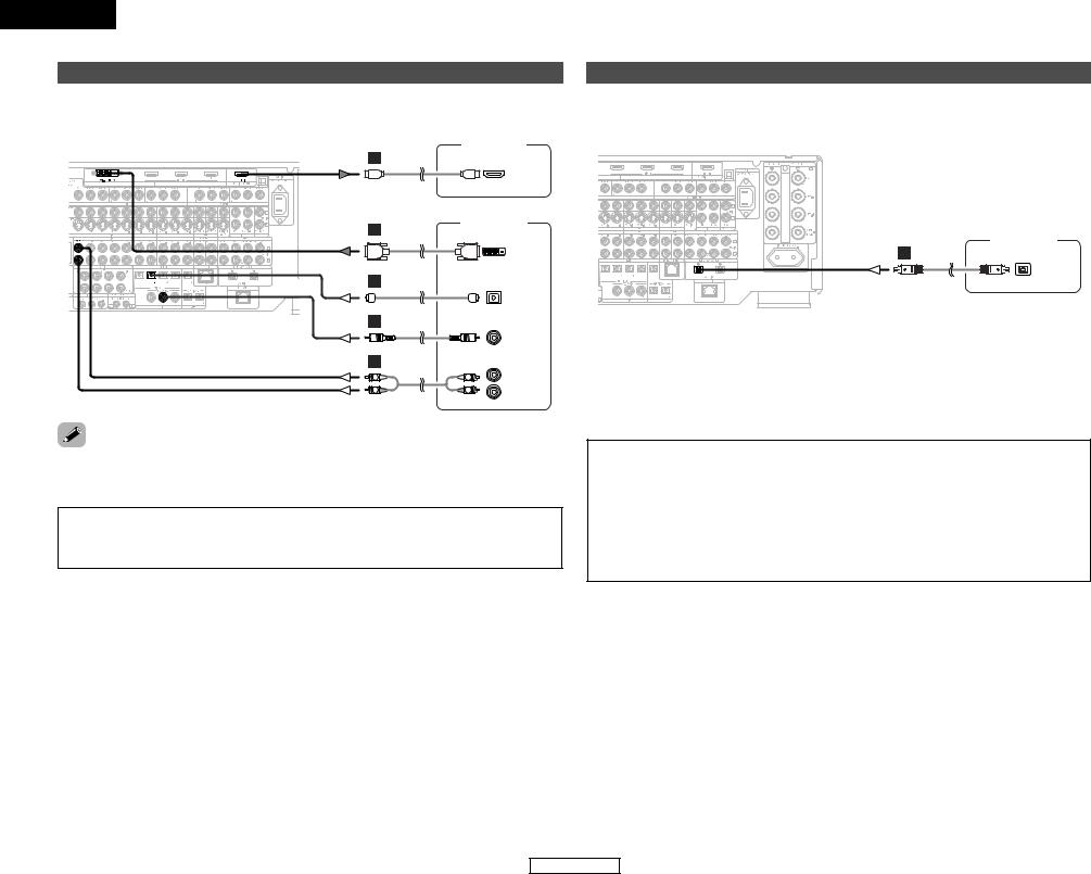
ENGLISH
Connecting Other Sources
Connecting equipment with DVI (Digital Visual Interface) terminals
•Connection with equipment that has a DVI (Digital Visual Interface)-D connector permits the transfer of digital images. Make an analog or digital audio connection also.
Monitor TV
L
HDMI
IN
DVD player
K
DVI-D
OUT
D
OPTICAL
OUT
C
COAXIAL
OUT
A |
|
AUDIO OUT |
|
|
|
L |
L |
L |
|
||
R |
R |
R |
connecting via a DVI-D cable, no digital audio will be output from the HDMI Monitor Out connector. digital TV monitor only supports DVI-D, please obtain and use an HDMI-DVI conversion cable or adaptor,
from your dealer.
-available DVI cables are available in 24-pin and 29-pin types. The AVC-A11XV supports the pin DVI-D cable.
AVC-A11XV supports HDCP. Use an HDCP-compatible HDMI monitor.
2 Connections with an HDMI/DVI-D conversion cable (adapter)
•The HDMI video stream signals (video signals) are theoretically compatible with DVI-D. When connecting to a monitor, etc., equipped with DVI-D terminals, it is possible to connect using an HDMI/DVI-D conversion cable, but depending on the combination of devices used the image might not be output.
•When using an HDMI/DVI-D conversion adapter, the image may not be output properly due to poor contact with the connected cable, etc..
•For stable signal transfer, we recommend using cables that are a maximum of 5 meters in length.
Connecting Other Sources
Connecting IEEE1394 devices
•For the digital transfer of signals from Super Audio CDs and DVD-Audio discs, connect using an IEEE1394 cable. For instructions on playing Super Audio CDs (  page 39).
•Assign the IEEE1394 input the input source. For details, see “Setting the IEEE1394 Assign” (  page 43, 44).
DVD player
F
IEEE1394
•IEEE1394 network
q Up to 17 devices can be connected using daisy chain type connections. w Up to 63 devices can be connected using tree type connections.
Do not loop the connections.
e “LINK CHECK” is displayed when an input source to which an IEEE1394 is assigned is selected and connection to the IEEE1394 device is being checked.
r If the connection is looped, “LOOP CONNECT” is displayed. Check the connections and undo the loop.
•The AVC-A11XV will not operate when connected to equipment other than that conforming to “IEEE1394 AUDIO (A&M protocol)” standards or when connected to computer peripherals.
Also please note that operation is not guaranteed even when connected to IEEE1394-compatible equipment. Whether or not data and control signals can be sent and received between interconnected IEEE1394-compatible equipment depends on the functions of the different equipment. Please read the operating instructions of the equipment to be connected.
•Use an S400-compatible 4-pin IEEE1394 cable to connect.
•Video signals are not transferred with the AVC-A11XV’s IEEE1394 interface, so when connecting a video device connect the video signals as well.
17
ENGLISH
Connecting Other Sources
Connecting the CONTROL terminals
These terminals are used for an external controller.
Perform the following operation before using an external controller connected to the RS-232C terminal:
1. Press the ON/STANDBY button on the main unit and set the unit to the operating mode.
2. Perform the operation to turn off the power from the external control.
3. Check that the product has been set to the standby mode.
After checking the above, check the connections of the external controller. Operation is possible.
Connecting the TRIGGER OUT terminals
Turn the DC 12V voltage on and off for the individual functions and surround modes. For details, see “Setting the Trigger Out” (  page 51).
ENGLISH
Connecting Other Sources
Connecting the MULTI ZONE terminals
For instructions on operations using the MULTI ZONE functions (  page 37 ~ 39).
ZONE2 (or ZONE3) pre-out connections
•If another power amplifier or pre-main (integrated) amplifier is connected, the ZONE2 (or ZONE3) pre-out (variable/fixed level) terminals can be used to play a different program source in ZONE2 (or ZONE3) the same time (  page 38).
•The ZONE2 (or ZONE3) video out is only for the ZONE2 (or ZONE3).
Monitor TV (ZONE2 or ZONE3)
|
H |
|
|
|
|
|
VIDEO |
|
|
|
IN |
|
I |
|
|
|
|
|
S VIDEO |
|
|
|
IN |
|
|
Power amplifier |
|
|
|
(ZONE2 or ZONE3) |
|
|
A |
|
|
|
L |
L |
L |
|
R |
R |
IN |
|
R |
||
|
INFRARED RETRANSMITTER |
INFRARED SENSOR |
|
|
+ |
+ |
|
|
AUX OUT |
|
|
Extension terminal for |
INPUT |
OUTPUT |
|
future use. |
|
||
|
|
|
|
NOTE:
•For the AUDIO output, use high quality pin-plug cables and wire in such a way that there is no humming or noise.
•For instructions on installation and operation of separately sold devices, refer to the devices’ operating instructions.
18
ENGLISH
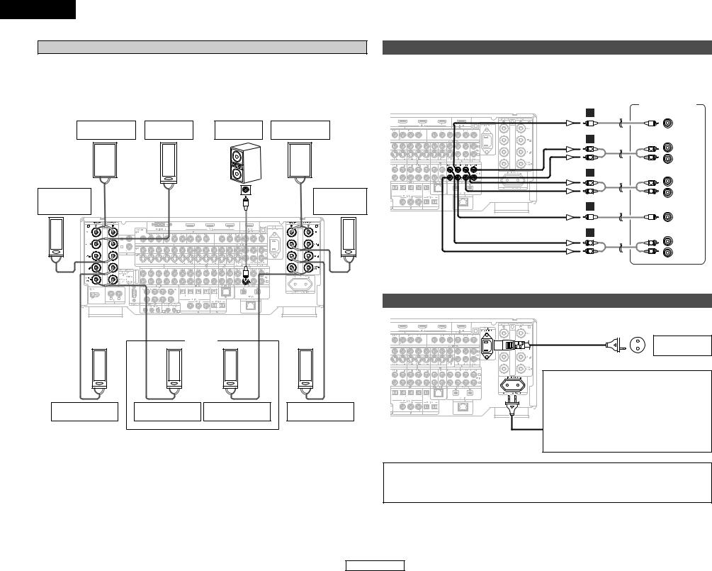
ENGLISH
Connecting Other Sources
ZONE2 / ZONE3 speaker out connections
•When the power amplifier is assigned to the ZONE2 or ZONE3 output channel at “Power Amp Assign” in the “System Setup Menu”, the MAIN ZONE speaker terminals can be used as the ZONE2 or ZONE3 speaker out terminals (  page 49, 50).
•The connections diagram below is an example for when the surround back speaker is assigned to the ZONE2 stereo 2 channel.
In this case, Surround Back Speaker OUT can not be used for MAIN ZONE.
Front |
Center |
Subwoofer |
Front |
|
|||
right speaker |
speaker |
left speaker |
|
||||
|
|
|
|||||
(R) |
|
|
|
|
|
(L) |
|
> < |
|
|
Connection terminal |
|
< |
> |
|
Surround |
> |
< |
IN |
|
Surround |
||
|
|
for subwoofer with |
|
||||
|
|
|
|
||||
right speaker |
|
|
built-in amplifier |
|
|
left speaker |
|
(A) |
|
|
(subwoofer), etc. |
|
|
(A) |
|
(R) |
|
|
|
|
|
|
(L) |
> < |
|
|
|
|
|
< |
> |
Connecting Other Sources
Connecting the pre-out terminals
•Use these terminals if you wish to connect external power amplifier(s) to increase the power of the front, center, surround and surround back sound channels, or for connection to powered loudspeakers.
•When using only one surround back speaker, connect it to left channel.
Power amplifier
B
|
|
CENTER |
|
A |
|
SURROUND |
|
L |
L |
BACK |
|
L |
|||
R |
R |
R |
|
A |
|
SURROUND |
|
L |
L |
||
L |
|||
R |
R |
R |
|
B |
|
|
|
|
|
SUB- |
|
|
|
WOOFER |
|
A |
|
FRONT |
|
L |
L |
||
L |
|||
R |
R |
R |
Connecting the power supply cord
|
|
ZONE2 |
|
(R) |
(R) |
(L) |
(L) |
> < |
> < |
< > |
< > |
Surround |
ZONE2 Front |
ZONE2 Front |
Surround |
right speaker (B) |
right speaker |
left speaker |
left speaker (B) |
Power supply cord
(Supplied) 
 AC outlets
(wall)
AC 230V, 50Hz
AC OUTLET
• SWITCHED (total capacity – 100 W)
The power to the outlet is turned on and off in conjunction with the POWER switch on the main unit, and when the power is switched between on and standby from the remote control unit.
No power is supplied from this outlet when this unit’s power is at standby. Never connect equipment whose total capacity is above 100 W.
NOTE:
•Only use the AC OUTLET for audio equipment. Never use them for hair driers, TVs or other electrical appliances.
•Insert the plugs securely. Incomplete connections will result in the generation of noise.
19
ENGLISH
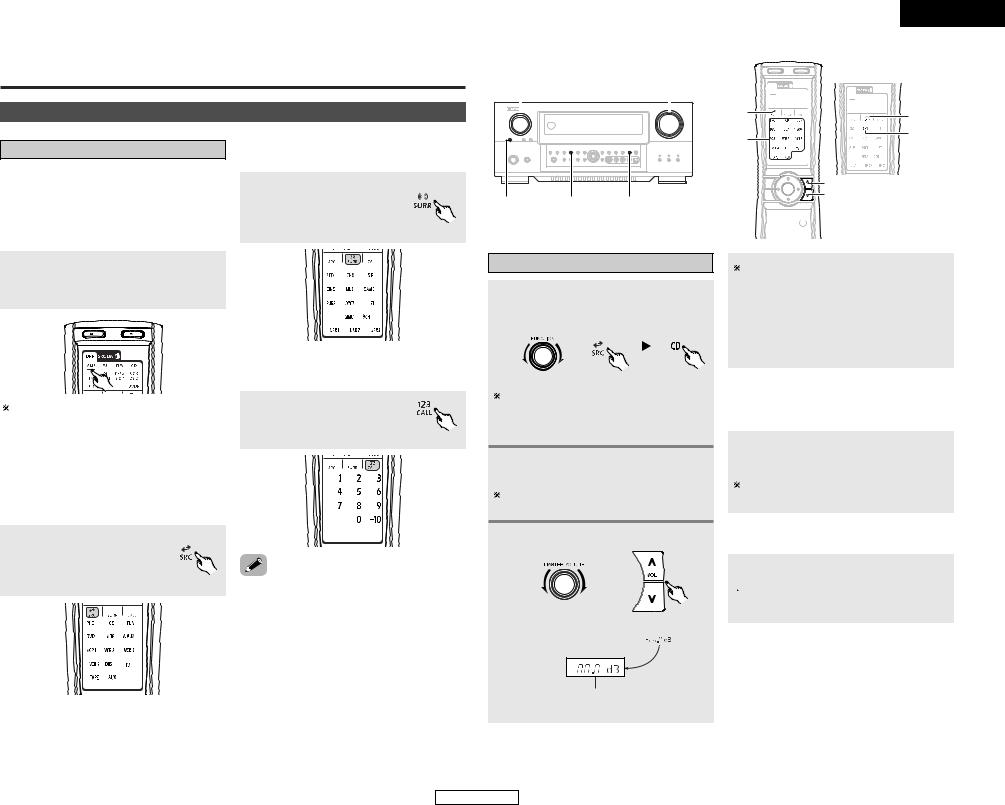
Basic Operation
Playback
Operating the remote control unit
The RC-995 remote control has a backlit LCD screen whose contents change according to the mode or function selected, with the appropriate remote commands for that mode or function.
2 Operate the this unit
The AMP button is the main mode for controlling the AVC-A11XV in the main room (MAIN ZONE).
The function switches as shown below each time one of the MODE SELECTOR buttons is pressed.
AMP/Z2 : AMP, ZONE2 Z3/Z4 : ZONE3, ZONE4*
(* : This mode can not be used with the AVCA11XV.)
MENU specific surround modes.
the SURROUND button the screen below to a specific surround
.
/ SYSTEM CALL MENU the “Number / System call” menu function.
the NUMBER / SYSTEM button to display the below.
2 SOURCE MENU
To operate the system’s source components.
Press the SOURCE button to display the screen shown below, to that you can select an input source.
•This function provides the ability to program a series of individual remote control codes into a macro stored under one of the number pad’s numeric choices (  page 32 ~ 35).
ENGLISH
Basic Operation
FUNCTION |
VOLUME |
|||||||||
|
|
|
|
|
|
|
|
|
|
|
|
|
|
|
|
|
|
|
|
|
|
|
|
|
|
|
|
|
|
|
|
|
|
|
|
|
|
|
|
|
|
|
|
SOURCE |
HOME THX |
ROOM EQ |
|
CINEMA |
|
SOURCE |
SURROUND |
|
|
||
FUNCTION |
HOME THX |
|
CINEMA |
||
|
 VOLUME
ROOM EQ 


Playing the input source
1 Select the input source to be played.
Example: CD
|
|
|
|
(Main unit) |
(Remote control unit) |
||
To select the input source when ZONE2 SELECT or ZONE3/REC SELECT is selected, press the SOURCE button on the main unit then operate the input function selector.
2 Start playback on the selected component.
For operating instructions, refer to the component’s manual.
Adjust the volume.
(Main unit) |
(Remote control unit) |
||
|
|
|
|
|
|
|
|
The volume can be adjusted within the range of –80 to +18 dB, in steps of 0.5 dB. However, when the channel level is set (  page 31 or 54, 55), if the volume for any channel is set at +0.5 dB or greater, the volume cannot be adjusted up to 18 dB. (In this case the maximum volume adjustment range is “18 dB — (Maximum value of channel level)”.)
2 To choose the surround sound mode
Example: THX Surround EX
Press the SURROUND button, then press the
HOME THX CINEMA button.
For more information about the surround modes (  page 24, 25).
2 To select the Room EQ function
ROOM EQ button.

 For more information about the Room EQ function (
  page 22).
M.VOL. -80.0dB
The volume level is displayed on the master volume level display.
20
ENGLISH
ENGLISH
Basic Operation
|
DIMMER |
VOLUME |
|
PHONES |
EXT. IN |
STATUS |
|
INPUT MODE |
ANALOG |
|
|
Playback using the external input (EXT. IN) terminals
Press the EXT. IN button to switch the external input.
•Cancelling the external input mode:
Press the INPUT MODE or ANALOG button to switch to the desired input mode ( page 21, 22).
•The external input mode can be set for any input source. To watch video while listening to sound, select the input source to which the video signal is connected, then set this mode.
•If the subwoofer output level seems too high, set the “SW ATT” surround parameter to “ON”.
NOTE:
•When the input mode is set to the external input (EXT. IN), the surround mode (DIRECT, STEREO, HOME THX CINEMA, STANDARD, 7CH STEREO, WIDE SCREEN or DSP SIMULATION) cannot be set.
•In play modes other than the external input mode, the signals connected to these terminals cannot be played. In addition, signals cannot be output from channels not connected to the input terminals.
 VOLUME


 ON SCREEN

 MUTING
VIDEO SELECT 


 SPEAKER
INPUT MODE 


 EXT. IN ANALOG


Turning the sound off temporarily (MUTING)
Use this to mute the audio output temporarily.
Press the MUTING button.
•You can adjust the muting level (  page 50).
•Cancelling MUTING mode:
Press the MUTING button again, or press the VOLUME button on the remote control, or adjust the volume up or down via the front panel VOLUME knob.
Listening over headphone
Connect the headphone to the PHONES jack.
•The pre-out output (including the speaker output) is automatically turned off when headphones are connected.
NOTE:
•To prevent hearing loss, be careful not to raise the volume level excessively when using headphones.
Combining the currently playing sound with the desired image (VIDEO SELECT)
Press the VIDEO SELECT button until the desired image appears.
D V D
V I D E O S O U R C E
The video source selected with the video select function is stored in the memory for the different input sources.
•Cancelling simulcast playback:
Select the “SOURCE” pressing the VIDEO SELECT button.
•It is not possible to select HDMI and DVI-D input signals.
Switching the surround speakers
Press the SPEAKER button.
The surround speakers switch as shown below each time the SPEAKER button is pressed.
 SURROUND A
 SURROUND B
SURROUND A+B
This operation is possible when the setting for using both surround speakers A and B is made at “Setting the type of speakers” ( page 53).
Checking the currently playing program source, etc.
2 On screen display
Press the ON SCREEN button.
Each time an operation is performed, a description of that operation appears on the display connected to AVC-A11XV’s VIDEO MONITOR OUT terminal. Also, the unit’s operating status can be checked during playback. Such information as the position of the input selector and the surround settings is output in sequence.
21
Basic Operation
2 Front panel display
Press the STATUS button.
Descriptions of the unit’s operations are also displayed on the front panel display. In addition, the display can be switched to check the unit’s operating status while playing a source.
2 Using the dimmer function
Use this to change the brightness of the display.
Press the DIMMER button.
The display brightness changes in four steps (bright, medium, dim and off).
Input mode
The AVC-A11XV has an AUTO signal detection mode that automatically identifies the type of incoming audio signals, but is also equipped with a manual mode that can be switched according to the type of input audio signals.
2Selecting the AUTO, PCM and DTS modes
Press the INPUT MODE button.
The mode switches as shown below each time the INPUT MODE button is pressed.
AUTO  PCM
PCM  DTS
DTS
AUTO: (All auto mode)
In this mode, the types of signals being input to the digital and analog input terminals for the selected input source are detected and the program in the AVC-A11XV’s surround decoder is selected automatically upon playback. This mode can be selected for all input sources other than PHONO.
The presence or absence of digital signals is detected, the signals input to the digital input terminals are identified and decoding and playback are performed automatically in DTS, Dolby Digital or PCM (2 channel stereo) format. If no digital signal is being input, the analog input terminals are selected.
Use this mode to play Dolby Digital signals.
ENGLISH
 Loading...